WO2014208016A1 - Procédé de fabrication d'un film étiré et dispositif de fabrication associé - Google Patents
Procédé de fabrication d'un film étiré et dispositif de fabrication associé Download PDFInfo
- Publication number
- WO2014208016A1 WO2014208016A1 PCT/JP2014/003003 JP2014003003W WO2014208016A1 WO 2014208016 A1 WO2014208016 A1 WO 2014208016A1 JP 2014003003 W JP2014003003 W JP 2014003003W WO 2014208016 A1 WO2014208016 A1 WO 2014208016A1
- Authority
- WO
- WIPO (PCT)
- Prior art keywords
- film
- stretched
- stretching
- disk
- transport
- Prior art date
- Legal status (The legal status is an assumption and is not a legal conclusion. Google has not performed a legal analysis and makes no representation as to the accuracy of the status listed.)
- Ceased
Links
Images





Classifications
-
- B—PERFORMING OPERATIONS; TRANSPORTING
- B29—WORKING OF PLASTICS; WORKING OF SUBSTANCES IN A PLASTIC STATE IN GENERAL
- B29C—SHAPING OR JOINING OF PLASTICS; SHAPING OF MATERIAL IN A PLASTIC STATE, NOT OTHERWISE PROVIDED FOR; AFTER-TREATMENT OF THE SHAPED PRODUCTS, e.g. REPAIRING
- B29C55/00—Shaping by stretching, e.g. drawing through a die; Apparatus therefor
- B29C55/02—Shaping by stretching, e.g. drawing through a die; Apparatus therefor of plates or sheets
- B29C55/04—Shaping by stretching, e.g. drawing through a die; Apparatus therefor of plates or sheets uniaxial, e.g. oblique
- B29C55/08—Shaping by stretching, e.g. drawing through a die; Apparatus therefor of plates or sheets uniaxial, e.g. oblique transverse to the direction of feed
Definitions
- the present invention relates to a method for manufacturing a stretched film that stretches in the width direction while transporting the film in the transport direction and a manufacturing apparatus therefor.
- the film is stretched in the width direction by gripping both ends of the film with clips provided on the chain and driving the chain in the direction of expanding the film in the width direction along the guide rail.
- a so-called tenter type stretched film production method is known (Patent Document 1).
- the stretched film manufacturing apparatus 101 employing the wire-type stretched film manufacturing method includes an outer periphery of the stretching roller 102 and an outer periphery of the transport rollers 103A, 103B, and 103C that transport the wire 104.
- the film 110 is stretched in the width direction by driving the wire 104 in the direction of expanding the film 110 in the width direction with the film 110 interposed therebetween.
- all of the side end portions of the film 110 are sandwiched by the wires 104, thereby suppressing the occurrence of neck-in and perforation in a part of the stretched film 110, and stretching unevenness hardly occurs in the stretched film 110.
- the film 110 is composed of the outer peripheral portion of the stretching roller 102 and the outer peripheral portions of the transport rollers 103A, 103B, and 103C.
- the stress is concentrated on the film 110 at the portion sandwiched between the outer peripheral portion of the stretching roller 102 and the outer peripheral portions of the transport rollers 103A and 103C disposed at both ends of the stretching section of the film 110.
- Cheap For this reason, it is difficult to stretch the film 110 while applying a uniform force in the transport direction of the film 110 in the stretching section of the film 110.
- An object of the present invention is to provide a method for producing a stretched film and a production apparatus capable of stretching the film while applying uniform force in the film transport direction in the stretched section of the film, which hardly causes stretch unevenness.
- the present invention A method for producing a stretched film that stretches in the width direction while transporting the film in the transport direction, In each of a part of the annular groove portion formed so as to extend along the outer peripheral portion of each of the stretched disks that are spread in the width direction from each other toward the transport direction and that are arranged so as to face each other.
- An endless wire movable along an endless track is mounted so as to sandwich both end portions of the film, and a transport roller is disposed along the inner periphery of the endless track to transport the film in the transport direction.
- the stretched disc provides a method for producing a stretched film disposed along the inner circumference of the endless track.
- the present invention also provides: An apparatus for producing a stretched film that stretches in the width direction while transporting the film in the transport direction, Stretched disks each extending in the width direction toward the transport direction and spaced apart so as to face each other, each formed with an annular groove along the outer periphery, Attached to each of a part of the groove portion of the stretching disk so as to sandwich both end portions of the film, and can move along an endless track so as to stretch in the width direction while transporting the film in the transport direction. Endless wire rods, A conveying roller disposed along the inner circumference of the endless track, The stretched disk provides a stretched film manufacturing apparatus disposed along the inner circumference of the endless track.
- the stretching disk is disposed along the inner periphery of the endless track, the film is not sandwiched between the outer periphery of the stretching disk and the outer periphery of the transport roller, and as a result, the stretching unevenness
- partial stress concentration on the film does not occur while using a wire that is effective in solving the problem. Therefore, it is possible to provide a stretched film manufacturing method and a manufacturing apparatus capable of stretching the film while suppressing the unevenness of stretching and applying a uniform force in the film transport direction in the stretching section of the film.
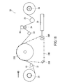
- FIG. 11 is a schematic side view when the second transport roller of the stretched film manufacturing apparatus of FIG. 10 is located further rearward and the first stretched disc and the second stretched disc are located further upward. It is a side schematic diagram of the conventional stretched film manufacturing apparatus.
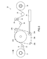
- FIG. 1 is a schematic side view of a stretched film manufacturing apparatus 1A employing the stretched film manufacturing method of the present embodiment
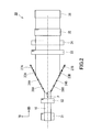
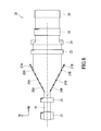
- FIG. 2 is a schematic plan view of the stretched film manufacturing apparatus 1A.
- a stretched film manufacturing apparatus 1A shown in FIGS. 1 and 2 is a stretched film manufacturing apparatus that stretches in the width direction (TD) while transporting the film 10 in the transport direction (MD).
- the film 10 is, for example, a polytetrafluoroethylene (PTFE) film, a polyethylene terephthalate (PET) film, a polyimide (PI) film, or the like.
- PTFE polytetrafluoroethylene
- PET polyethylene terephthalate
- PI polyimide
- the stretched film manufacturing apparatus 1A includes a supply roller 31, a first pressing roller 32, a first stretching disk 23A and a second stretching disk 23B, a first wire 24A and a second wire 24B, and first transport rollers 25A and 25B.
- a take-up roller 36. 2 is a schematic view of the stretched film manufacturing apparatus 1A as viewed from the right side face in the transport direction.
- FIG. 2 shows the first stretch disk 23A, the first wire 24A, and the first transport roller 25A.
- the second transport roller 26A and the third transport roller 27A are not shown, but each configuration of the first stretching disk 23A, the first wire 24A, the first transport roller 25A, the second transport roller 26A, and the third transport roller 27A These are the same as the respective configurations of the second stretching disk 23B, the second wire 24B, the first transport roller 25B, the second transport roller 26B, and the third transport roller 27B, and the illustration thereof is omitted.
- the supply roller 31 is a member for feeding out the film 10 wound around the outer peripheral portion in the transport direction.
- the supply roller 31 rotates counterclockwise when viewed from the right side surface, and with this rotation, the film 10 is fed out from the lower portion of the supply roller 31 in the transport direction.
- the first pressing roller 32 is disposed on the front side in the transport direction of the supply roller 31.
- the first pressing roller 32 is a member that is disposed at a position in contact with the upper surface of the film 10 that is fed from the supply roller 31 and presses the film 10 downward.
- the first pressing roller 32 is configured to be movable in the vertical direction and fixed at an arbitrary position in the vertical direction.
- the lower end of the first pressing roller 32 is positioned below the upper ends of the first stretching disk 23A and the second stretching disk 23B, and applies tension to the film 10.
- the first stretching disk 23A and the second stretching disk 23B are members that stretch the film 10 in the width direction.
- the first stretching disk 23 ⁇ / b> A and the second stretching disk 23 ⁇ / b> B are disposed on the front side in the transport direction of the first pressing roller 32.
- the first stretching disk 23A and the second stretching disk 23B extend in the width direction toward the transport direction and are arranged at an interval so as to face each other.
- the first stretching disk 23A and the second stretching disk 23B are disk-shaped members, respectively, and are formed with annular first groove portions 28A and second groove portions 28B along the outer peripheral portion.
- a film is formed on a part of the first groove part 28A and the second groove part 28B, specifically, on a part of the first groove part 28A and the second groove part 28B located above the first extending disk 23A and the second extending disk 23B.
- the first wire 24A and the second wire 24B are attached so that both side end portions of 10 are sandwiched between the first groove portion 28A and the second groove portion 28B.
- the first wire 24A and the second wire 24B move, so that the film 10
- the film is stretched in the width direction while being transported in the transport direction.
- the first stretching disk 23 ⁇ / b> A and the second stretching disk 23 ⁇ / b> B are arranged so that the surface direction of the disk coincides with the direction perpendicular to the surface of the film 10.
- the stretching ratio in the width direction of the film 10 can be adjusted by changing the positions of the first stretching disk 23A and the second stretching disk 23B.
- the stretching ratio in the width direction of the film 10 can be adjusted by changing the angle at which the first stretching disk 23A and the second stretching disk 23B face each other.
- the stretching ratio in the width direction of the film 10 is such that the first wire 24A at the front end portion (stretching end portion) in the transport direction with respect to the distance between the first wire 24A and the second wire 24B at the rear end portion (stretching start portion) in the transport direction. And the ratio of the distance between the second wire 24B. As shown in FIG.
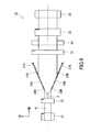
- the first stretching disk 23A and the second stretching disk 23B are centered on the point P so that the angle at which the first stretching disk 23A and the second stretching disk 23B face each other becomes smaller ( ⁇ 9 ⁇ 2 ). Is moved, the stretching ratio of the film 10 is decreased, and the length in the width direction of the stretched film 10 is decreased.
- the angle at which the first stretching disk 23A and the second stretching disk 23B face each other is adjusted by adjusting the first stretching disk 23A and the second stretching disk 23B, the first transport rollers 25A and 25B, the second transport rollers 26A and 26B, and the third transport roller. This is done by moving the unit containing 27A and 27B.
- the point P is an intersection of the straight line which connects a conveyance direction front end part and the back end part when it observes from the direction perpendicular
- the first wire 24A and the second wire 24B are endless wires that can move along an endless track so as to extend in the width direction while transporting the film 10 in the transport direction.
- the first wire 24A and the second wire 24B are metal wires.
- the first stretching disk 23A and the second stretching disk 23B, the first transport rollers 25A and 25B, the second transport rollers 26A and 26B, and the third transport rollers 27A and 27B are in the endless track of the first wire 24A and the second wire 24B. Arranged along the inner periphery, tension is applied to the first wire 24A and the second wire 24B.
- the first wire 24A and the second wire 24B are not limited to metal wires, and may be metal or resin chains.
- the first transport rollers 25A and 25B are arranged along the inner circumference of the endless track of the first wire 24A and the second wire 24B.
- the first transport rollers 25A and 25B are free rollers that are rotatably arranged.
- the first transport rollers 25A and 25B are disposed below the first stretching disk 23A and the second stretching disk 23B.
- the second transport rollers 26A and 26B are drive rollers disposed along the inner circumference of the endless track of the first wire 24A and the second wire 24B.
- the second transport rollers 26A and 26B are configured to be rotatable in a predetermined direction (clockwise direction when viewed from the right side surface) by a driving force of a power source (not shown).
- the second transport rollers 26A and 26B are also disposed below the first stretching disk 23A and the second stretching disk 23B.
- a tension control device 29 is connected to the second transport rollers 26A and 26B, and the second transport rollers 26A and 26B can be moved in the front-rear direction by the tension control device 29 and at any position in the front-rear direction. It can be fixed.
- the tension control device 29 has a telescopic arm fixed to the rotation shafts of the second transport rollers 26A and 26B, and extends and retracts the second transport rollers 26A and 26B in the front-rear direction. The tension acting on the first wire 24A and the second wire 24B is adjusted.
- the third transport rollers 27A and 27B are arranged along the inner circumference of the endless track of the first wire 24A and the second wire 24B.
- the third transport rollers 27A and 27B are disposed in front of the first stretching disk 23A and the second stretching disk 23B in the transport direction.
- the third transport rollers 27A and 27B are free rollers that are rotatably arranged.
- the third transport rollers 27A and 27B are movable in the vertical direction and can be fixed at arbitrary positions in the vertical direction. When the third transport rollers 27A and 27B are moved upward, the stretch ratio is decreased, and when the third transport rollers 27A and 27B are moved downward, the stretch ratio is increased.
- the stretching ratio in the width direction of the film 10 can also be adjusted by changing the positions of the third transport rollers 27A and 27B.
- the stretching ratio in the width direction of the film 10 can be adjusted by moving the third transport rollers 27A and 27B in the vertical direction.
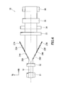
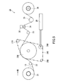
- FIGS. 3 and 4 when the third transport rollers 27A and 27B are moved to the upper position, the first wire 24A and the second wire 24B at the front end in the transport direction of the stretched section of the film 10 are disposed. Since the distance becomes smaller, the length in the width direction of the stretched film 10 becomes smaller. As shown in FIGS.
- the method of adjusting the draw ratio in the width direction of the film 10 by changing the position of the transport roller is not limited to the movement of the third transport rollers 27A and 27B.
- the second transport rollers 26A and 26B are moved in the front-rear direction without providing the third transport rollers 27A and 27B, thereby stretching the film 10 in the width direction.
- the magnification may be adjusted.
- the second transport rollers 26 ⁇ / b> A and 26 ⁇ / b> B are positioned forward, the distance between the first wire 24 ⁇ / b> A and the second wire 24 ⁇ / b> B at the front end portion of the stretching section of the film 10 is reduced.
- the length in the width direction becomes smaller.
- the stretching section of the film 10 is expanded, and the length in the width direction of the stretched film 10 is increased.
- the second pressing roller 33 is disposed on the front side in the transport direction of the third transport rollers 27A and 27B.
- the 2nd press roller 33 is a member for arrange
- the second pressing roller 33 is configured to be movable in the vertical direction and fixed at an arbitrary position in the vertical direction.
- the lower end of the second pressing roller 33 is positioned below the upper end of the delivery roller 34 and applies tension to the film 10.
- the delivery roller 34 is a member for feeding out the film 10 fed from the first stretching disk 23A and the second stretching disk 23B in the transport direction.
- the delivery roller 34 rotates clockwise as viewed from the right side surface.
- a film cutting device 30 for cutting both end portions of the film 10 is disposed above the feed roller 34.
- the film cutting device 30 is a device for cutting both side ends of the film 10 so that the width of the film 10 becomes a predetermined length.
- the film cutting device 30 is a general-purpose rotary sheet cutter that cuts both end portions of the film 10 with two rotating cutters, for example.
- the third pressing roller 35 is disposed on the front side in the carry-out direction of the delivery roller 34.
- the third pressing roller 35 is a member that is disposed at a position that comes into contact with the upper surface of the film 10 that is fed from the delivery roller 34 and presses the film 10 downward.
- the third pressing roller 35 is movable in the vertical direction and can be fixed at an arbitrary position in the vertical direction.
- the lower end of the third pressing roller 35 is positioned below the upper end of the take-up roller 36 and applies tension to the film 10.
- the take-up roller 36 is a member for winding the film 10 fed from the feed roller 34 around the outer periphery.
- the winding roller 36 rotates clockwise as viewed from the right side surface.
- the film 10 is taken up from the upper part of the take-up roller 36.
- the stretched film manufacturing apparatus 1 ⁇ / b> A may be configured to adjust the stretch ratio in the transport direction of the film 10 by applying a predetermined tension in the transport direction of the film 10. For example, the conveyance speed of the film 10 between the supply roller 31 and the first stretching disk 23A and the second stretching disk 23B, and the film 10 between the first stretching disk 23A and the second stretching disk 23B and the take-up roller 36. You may make it adjust the draw ratio of the conveyance direction of the film 10 by varying the conveyance speed of this.
- the stretched film manufacturing apparatus 1 ⁇ / b> A is provided between the supply roller 31 and the first stretched disk 23 ⁇ / b> A and the second stretched disk 23 ⁇ / b> B and / or between the first stretched disk 23 ⁇ / b> A and the second stretched disk 23 ⁇ / b> B and the take-up roller 36.
- a heater for heating or drying the film 10 may be further included. Or you may arrange
- the first stretching disk 23A and the second stretching disk 23B are disposed along the inner circumference of the endless track of the first wire 24A and the second wire 24B.
- the film 10 is not sandwiched between the outer periphery of the disk 23A and the second stretched disk 23B and the outer periphery of the first transport rollers 25A and 25B, the second transport rollers 26A and 26B, and the third transport rollers 27A and 27B.
- partial stress concentration on the film 10 does not occur while using the first wire 24A and the second wire 24B that are effective in eliminating the stretching unevenness. Therefore, it is possible to stretch the film 10 while applying a uniform force in the transport direction of the film 10 in the stretching section of the film 10 while suppressing stretching unevenness.
- the above-described configuration of the present embodiment includes a magnification adjusting mechanism that adjusts the stretching ratio in the width direction of the film by changing the position of the transport roller and / or the stretching disk.
- a magnification adjusting mechanism that adjusts the stretching ratio in the width direction of the film by changing the position of the transport roller and / or the stretching disk.
- a known device that moves the position of the shaft that is the rotation center of the transport roller or the stretching disk can be used.
- the change of the position of the conveying roller and / or the stretching disk can be performed not only by the parallel movement of the roller and the disk, but also by changing the direction (posture) (rotational movement) or a combination thereof.
- PTFE fine powder Polyflon Fine Powder F106, manufactured by Daikin Industries
- hydrocarbon oil Isopar M, manufactured by Esso Petroleum
- the sheet was obtained by extruding into a paste.
- the obtained sheet was passed between metal rolling rolls and rolled to a thickness of 400 ⁇ m to obtain a raw roll.
- the obtained rolled material was dried in a drying furnace at 170 ° C. to obtain a PTFE sheet (PTFE film).
- the obtained PTFE film was stretched at a stretch ratio of 1 time in the transport direction and 4.5 times in the width direction in the stretched film manufacturing apparatus 1A of the present embodiment, and stretched to 200 ⁇ m.
- the stretched film production method and production apparatus of the present invention can be suitably used for stretching thin films such as PTFE films, PET films, and PI films. Moreover, the manufacturing method and its manufacturing apparatus of the stretched film of this invention can be used for the use similar to the manufacturing method and its manufacturing apparatus of the conventional stretched film.
Landscapes
- Engineering & Computer Science (AREA)
- Mechanical Engineering (AREA)
- Shaping By String And By Release Of Stress In Plastics And The Like (AREA)
Abstract
Des disques d'étirage (23A, 23B) sont disposés avec un espace entre eux de sorte que, le long de la direction de transport, les disques s'écartent l'un de l'autre dans la direction de la largeur et se font face l'un à l'autre. Des rainures circulaires (28A, 28B), qui suivent les circonférences extérieures des disques, sont formées. Des fils (24A, 24B) sont installés de manière à faire rentrer les deux bords du film dans les rainures (28A, 28B) et déplacer le film le long des chenilles de façon à étirer le film dans la direction de la largeur tout en étant transporté le long de la direction de transport. Des rouleaux de transport (25A - 27B) sont disposés le long des circonférences internes des chenilles des fils (24A, 24B). Les disques d'étirage (23A, 23B) sont disposés le long des circonférences internes des chenilles des fils (24A, 24B).
Applications Claiming Priority (2)
| Application Number | Priority Date | Filing Date | Title |
|---|---|---|---|
| JP2013133433A JP6190637B2 (ja) | 2013-06-26 | 2013-06-26 | 延伸フィルムの製造方法及びその製造装置 |
| JP2013-133433 | 2013-06-26 |
Publications (1)
| Publication Number | Publication Date |
|---|---|
| WO2014208016A1 true WO2014208016A1 (fr) | 2014-12-31 |
Family
ID=52141391
Family Applications (1)
| Application Number | Title | Priority Date | Filing Date |
|---|---|---|---|
| PCT/JP2014/003003 Ceased WO2014208016A1 (fr) | 2013-06-26 | 2014-06-05 | Procédé de fabrication d'un film étiré et dispositif de fabrication associé |
Country Status (2)
| Country | Link |
|---|---|
| JP (1) | JP6190637B2 (fr) |
| WO (1) | WO2014208016A1 (fr) |
Cited By (3)
| Publication number | Priority date | Publication date | Assignee | Title |
|---|---|---|---|---|
| WO2017215731A1 (fr) * | 2016-06-13 | 2017-12-21 | Globra Gmbh | Structure de base, dispositif et procédé pour transporter une feuille |
| CN107826842A (zh) * | 2017-12-02 | 2018-03-23 | 佛山市高明区业臻设备有限公司 | 一种薄膜扩幅装置 |
| CN112768151A (zh) * | 2020-12-31 | 2021-05-07 | 中国人民解放军96901部队23分队 | 一种低噪声电缆用耐辐照交联聚四氟乙烯薄膜的制备方法 |
Families Citing this family (2)
| Publication number | Priority date | Publication date | Assignee | Title |
|---|---|---|---|---|
| JP6167987B2 (ja) * | 2014-05-14 | 2017-07-26 | トヨタ自動車株式会社 | 膜材搬送方法および膜材延伸装置 |
| CN104723546B (zh) * | 2015-03-25 | 2017-04-05 | 华南理工大学 | 基于鞍形曲面过渡的薄膜无级双向拉伸方法 |
Citations (5)
| Publication number | Priority date | Publication date | Assignee | Title |
|---|---|---|---|---|
| JPS58120017U (ja) * | 1982-02-09 | 1983-08-16 | 株式会社神戸製鋼所 | プラスチツクフイルム等の延伸装置 |
| JPH04133718A (ja) * | 1990-09-26 | 1992-05-07 | Nippon Petrochem Co Ltd | 延伸機 |
| JPH04173333A (ja) * | 1990-11-08 | 1992-06-22 | Nippon Petrochem Co Ltd | 積層体の製造方法およびその製造装置ならびにこの積層体に用いられる網状体の製造方法およびその製造装置 |
| JPH04298325A (ja) * | 1991-03-27 | 1992-10-22 | Nippon Petrochem Co Ltd | 横延伸装置 |
| JPH07144359A (ja) * | 1992-04-03 | 1995-06-06 | Polymer Processing Res Inst | 回転円盤によるヨコ延伸ウェブの製法および装置 |
Family Cites Families (6)
| Publication number | Priority date | Publication date | Assignee | Title |
|---|---|---|---|---|
| JPS50133272A (fr) * | 1974-04-10 | 1975-10-22 | ||
| JPS618325A (ja) * | 1984-06-21 | 1986-01-16 | Nitta Kk | シ−トの延伸方法およびその装置 |
| JPS61160222A (ja) * | 1985-01-07 | 1986-07-19 | Mitsubishi Petrochem Co Ltd | 熱可塑性樹脂フイルムの縦延伸方法 |
| JPS649236A (en) * | 1987-07-02 | 1989-01-12 | Showa Denko Kk | Production of piezoelectric film |
| JP5072542B2 (ja) * | 2007-11-08 | 2012-11-14 | タツモ株式会社 | 光学フィルム加圧装置 |
| JP4633834B2 (ja) * | 2008-10-22 | 2011-02-16 | トヨタ自動車株式会社 | 膜延伸装置 |
-
2013
- 2013-06-26 JP JP2013133433A patent/JP6190637B2/ja active Active
-
2014
- 2014-06-05 WO PCT/JP2014/003003 patent/WO2014208016A1/fr not_active Ceased
Patent Citations (5)
| Publication number | Priority date | Publication date | Assignee | Title |
|---|---|---|---|---|
| JPS58120017U (ja) * | 1982-02-09 | 1983-08-16 | 株式会社神戸製鋼所 | プラスチツクフイルム等の延伸装置 |
| JPH04133718A (ja) * | 1990-09-26 | 1992-05-07 | Nippon Petrochem Co Ltd | 延伸機 |
| JPH04173333A (ja) * | 1990-11-08 | 1992-06-22 | Nippon Petrochem Co Ltd | 積層体の製造方法およびその製造装置ならびにこの積層体に用いられる網状体の製造方法およびその製造装置 |
| JPH04298325A (ja) * | 1991-03-27 | 1992-10-22 | Nippon Petrochem Co Ltd | 横延伸装置 |
| JPH07144359A (ja) * | 1992-04-03 | 1995-06-06 | Polymer Processing Res Inst | 回転円盤によるヨコ延伸ウェブの製法および装置 |
Cited By (4)
| Publication number | Priority date | Publication date | Assignee | Title |
|---|---|---|---|---|
| WO2017215731A1 (fr) * | 2016-06-13 | 2017-12-21 | Globra Gmbh | Structure de base, dispositif et procédé pour transporter une feuille |
| US11235509B2 (en) | 2016-06-13 | 2022-02-01 | Globra Gmbh | Device and method for transporting film |
| CN107826842A (zh) * | 2017-12-02 | 2018-03-23 | 佛山市高明区业臻设备有限公司 | 一种薄膜扩幅装置 |
| CN112768151A (zh) * | 2020-12-31 | 2021-05-07 | 中国人民解放军96901部队23分队 | 一种低噪声电缆用耐辐照交联聚四氟乙烯薄膜的制备方法 |
Also Published As
| Publication number | Publication date |
|---|---|
| JP2015006775A (ja) | 2015-01-15 |
| JP6190637B2 (ja) | 2017-08-30 |
Similar Documents
| Publication | Publication Date | Title |
|---|---|---|
| JP6190637B2 (ja) | 延伸フィルムの製造方法及びその製造装置 | |
| JP4633834B2 (ja) | 膜延伸装置 | |
| JP6622680B2 (ja) | 縦延伸装置 | |
| JP5617608B2 (ja) | フィルム耳の切取回収装置、長尺の光学フィルムの製造方法、及びフィルム耳の巻回体の製造方法 | |
| JP5688858B2 (ja) | 機能性フィルムの製造方法、及びウエブ搬送装置 | |
| JP5681794B2 (ja) | ベルトジャンクションコンベヤ | |
| JP6551237B2 (ja) | 溝付ローラー、ならびにこれを用いたプラスチックフィルムの製造装置および製造方法 | |
| JP7588505B2 (ja) | ロール装置 | |
| JPWO2010005102A1 (ja) | プラスチックフィルム延伸装置 | |
| JP2014108616A (ja) | タイヤ成形用部材の製造装置と製造方法およびタイヤの製造方法 | |
| US3339441A (en) | Feeding and corrugating means for package wrapping machines | |
| JP5384585B2 (ja) | 溶液製膜方法 | |
| JP2010177343A (ja) | 薄膜積層体の製造装置 | |
| JP6252301B2 (ja) | 樹脂フィルム加工装置 | |
| JP5947747B2 (ja) | 張力制御装置 | |
| JP6036608B2 (ja) | 塗工装置 | |
| JP6405724B2 (ja) | 樹脂フィルム加工装置 | |
| US20200189870A1 (en) | Passive edge guiding method and apparatus | |
| JP2015217528A (ja) | 膜材搬送方法および膜材延伸装置 | |
| JP2006347027A (ja) | ゴムチェーファー付きインナーライナの製造方法、及び、空気入りタイヤの製造方法 | |
| JP6180418B2 (ja) | 伸縮積層体の製造方法および装置 | |
| WO2024154395A1 (fr) | Transporteur de film, méthode de transport de film et dispositif de production de film | |
| JP6255218B2 (ja) | 包装機、及び包装体の製造方法 | |
| JP2021134017A (ja) | シート状物の加熱制御装置 | |
| JP2013209212A (ja) | 巻取方法、搬送装置 |
Legal Events
| Date | Code | Title | Description |
|---|---|---|---|
| 121 | Ep: the epo has been informed by wipo that ep was designated in this application |
Ref document number: 14817778 Country of ref document: EP Kind code of ref document: A1 |
|
| NENP | Non-entry into the national phase |
Ref country code: DE |
|
| 122 | Ep: pct application non-entry in european phase |
Ref document number: 14817778 Country of ref document: EP Kind code of ref document: A1 |