WO2014208029A1 - Compresseur à volute - Google Patents
Compresseur à volute Download PDFInfo
- Publication number
- WO2014208029A1 WO2014208029A1 PCT/JP2014/003106 JP2014003106W WO2014208029A1 WO 2014208029 A1 WO2014208029 A1 WO 2014208029A1 JP 2014003106 W JP2014003106 W JP 2014003106W WO 2014208029 A1 WO2014208029 A1 WO 2014208029A1
- Authority
- WO
- WIPO (PCT)
- Prior art keywords
- partition wall
- scroll
- refrigerant
- port portion
- downstream
- Prior art date
- Legal status (The legal status is an assumption and is not a legal conclusion. Google has not performed a legal analysis and makes no representation as to the accuracy of the status listed.)
- Ceased
Links
Images

Classifications
-
- F—MECHANICAL ENGINEERING; LIGHTING; HEATING; WEAPONS; BLASTING
- F04—POSITIVE - DISPLACEMENT MACHINES FOR LIQUIDS; PUMPS FOR LIQUIDS OR ELASTIC FLUIDS
- F04C—ROTARY-PISTON, OR OSCILLATING-PISTON, POSITIVE-DISPLACEMENT MACHINES FOR LIQUIDS; ROTARY-PISTON, OR OSCILLATING-PISTON, POSITIVE-DISPLACEMENT PUMPS
- F04C18/00—Rotary-piston pumps specially adapted for elastic fluids
- F04C18/02—Rotary-piston pumps specially adapted for elastic fluids of arcuate-engagement type, i.e. with circular translatory movement of co-operating members, each member having the same number of teeth or tooth-equivalents
- F04C18/0207—Rotary-piston pumps specially adapted for elastic fluids of arcuate-engagement type, i.e. with circular translatory movement of co-operating members, each member having the same number of teeth or tooth-equivalents both members having co-operating elements in spiral form
- F04C18/0215—Rotary-piston pumps specially adapted for elastic fluids of arcuate-engagement type, i.e. with circular translatory movement of co-operating members, each member having the same number of teeth or tooth-equivalents both members having co-operating elements in spiral form where only one member is moving
-
- F—MECHANICAL ENGINEERING; LIGHTING; HEATING; WEAPONS; BLASTING
- F04—POSITIVE - DISPLACEMENT MACHINES FOR LIQUIDS; PUMPS FOR LIQUIDS OR ELASTIC FLUIDS
- F04C—ROTARY-PISTON, OR OSCILLATING-PISTON, POSITIVE-DISPLACEMENT MACHINES FOR LIQUIDS; ROTARY-PISTON, OR OSCILLATING-PISTON, POSITIVE-DISPLACEMENT PUMPS
- F04C29/00—Component parts, details or accessories of pumps or pumping installations, not provided for in groups F04C18/00 - F04C28/00
- F04C29/06—Silencing
- F04C29/061—Silencers using overlapping frequencies, e.g. Helmholtz resonators
-
- F—MECHANICAL ENGINEERING; LIGHTING; HEATING; WEAPONS; BLASTING
- F04—POSITIVE - DISPLACEMENT MACHINES FOR LIQUIDS; PUMPS FOR LIQUIDS OR ELASTIC FLUIDS
- F04C—ROTARY-PISTON, OR OSCILLATING-PISTON, POSITIVE-DISPLACEMENT MACHINES FOR LIQUIDS; ROTARY-PISTON, OR OSCILLATING-PISTON, POSITIVE-DISPLACEMENT PUMPS
- F04C29/00—Component parts, details or accessories of pumps or pumping installations, not provided for in groups F04C18/00 - F04C28/00
- F04C29/06—Silencing
- F04C29/068—Silencing the silencing means being arranged inside the pump housing
-
- F—MECHANICAL ENGINEERING; LIGHTING; HEATING; WEAPONS; BLASTING
- F04—POSITIVE - DISPLACEMENT MACHINES FOR LIQUIDS; PUMPS FOR LIQUIDS OR ELASTIC FLUIDS
- F04C—ROTARY-PISTON, OR OSCILLATING-PISTON, POSITIVE-DISPLACEMENT MACHINES FOR LIQUIDS; ROTARY-PISTON, OR OSCILLATING-PISTON, POSITIVE-DISPLACEMENT PUMPS
- F04C18/00—Rotary-piston pumps specially adapted for elastic fluids
- F04C18/02—Rotary-piston pumps specially adapted for elastic fluids of arcuate-engagement type, i.e. with circular translatory movement of co-operating members, each member having the same number of teeth or tooth-equivalents
- F04C18/0207—Rotary-piston pumps specially adapted for elastic fluids of arcuate-engagement type, i.e. with circular translatory movement of co-operating members, each member having the same number of teeth or tooth-equivalents both members having co-operating elements in spiral form
- F04C18/0246—Details concerning the involute wraps or their base, e.g. geometry
- F04C18/0253—Details concerning the base
- F04C18/0261—Details of the ports, e.g. location, number, geometry
-
- F—MECHANICAL ENGINEERING; LIGHTING; HEATING; WEAPONS; BLASTING
- F04—POSITIVE - DISPLACEMENT MACHINES FOR LIQUIDS; PUMPS FOR LIQUIDS OR ELASTIC FLUIDS
- F04C—ROTARY-PISTON, OR OSCILLATING-PISTON, POSITIVE-DISPLACEMENT MACHINES FOR LIQUIDS; ROTARY-PISTON, OR OSCILLATING-PISTON, POSITIVE-DISPLACEMENT PUMPS
- F04C23/00—Combinations of two or more pumps, each being of rotary-piston or oscillating-piston type, specially adapted for elastic fluids; Pumping installations specially adapted for elastic fluids; Multi-stage pumps specially adapted for elastic fluids
- F04C23/008—Hermetic pumps
-
- F—MECHANICAL ENGINEERING; LIGHTING; HEATING; WEAPONS; BLASTING
- F04—POSITIVE - DISPLACEMENT MACHINES FOR LIQUIDS; PUMPS FOR LIQUIDS OR ELASTIC FLUIDS
- F04C—ROTARY-PISTON, OR OSCILLATING-PISTON, POSITIVE-DISPLACEMENT MACHINES FOR LIQUIDS; ROTARY-PISTON, OR OSCILLATING-PISTON, POSITIVE-DISPLACEMENT PUMPS
- F04C29/00—Component parts, details or accessories of pumps or pumping installations, not provided for in groups F04C18/00 - F04C28/00
- F04C29/12—Arrangements for admission or discharge of the working fluid, e.g. constructional features of the inlet or outlet
Definitions
- the present invention relates to a scroll compressor constituting, for example, an indoor air conditioner.
- a scroll compressor used in a refrigeration cycle such as an air conditioner or a refrigeration apparatus includes a fixed scroll and a turning scroll.
- the fixed scroll and the orbiting scroll are each formed by integrally forming a spiral wrap wall on one surface side of a disk-shaped end plate.
- Such a fixed scroll and the orbiting scroll are made to face each other with the lap wall meshed, and the orbiting scroll is caused to revolve with an electric motor or the like with respect to the fixed scroll. Then, the refrigerant gas in the compression chamber is compressed by reducing the volume while moving the compression chamber formed between both wrap walls from the outer peripheral side to the inner peripheral side.
- the refrigerant gas compressed in the compression chamber passes through the discharge port formed in the end plate of the fixed scroll, flows into the high pressure chamber between the discharge cover and the housing, and further from the discharge pipe provided in the housing to the refrigerant circuit. It is discharged toward.
- Patent Document 1 proposes fitting a hollow cylindrical collar to the discharge port in order to suppress vibration and noise due to the discharge of fluid compressed by the turning motion of the scroll. By providing the collar, the excitation force of the in-cylinder pressure pulsation can be reduced, and an increase in compressor noise can be suppressed.
- the vibration and noise generated by the scroll compressor covers a wide frequency range. Therefore, it is difficult to reduce noise in all frequency regions with one noise reduction means. Therefore, it is necessary to take measures according to the frequency to be reduced. For example, since the volume of a discharge port provided with a collar in Patent Document 1 is limited, it is difficult to reduce noise in a low frequency region.
- the present invention has been made based on such a technical problem, and an object of the present invention is to provide a scroll compressor that can reduce noise in an arbitrary frequency band generated in the scroll compressor.
- the resonance frequency at the discharge port can be changed.
- the discharge port provided in the fixed scroll is divided into an upstream port portion and a downstream port portion, and the volume of the downstream port portion is increased to function as a muffler.
- the downstream port part is divided into a plurality of rooms, a resonance frequency different from that of the downstream port part not provided with a partition is realized, thereby reducing sound in an arbitrary frequency band.
- a plurality of partitioned rooms need to function as refrigerant passages.
- the scroll compressor according to the present invention forms a turning scroll that is rotatably connected to the eccentric shaft portion of the main shaft, a compression chamber that compresses the refrigerant by facing the turning scroll, and the compressed refrigerant is high-pressure.
- the fixed scroll which has the discharge port which discharges toward a chamber in an end plate, and the discharge cover which covers a discharge port are provided.
- the discharge port has an upstream port portion provided on the upstream side in the refrigerant inflow direction, and a downstream port portion provided on the downstream side in the refrigerant inflow direction and having a larger volume than the upstream port portion. It consists of.
- the downstream port portion includes a partition wall that divides the interior into a plurality of regions, and a refrigerant passage through which the refrigerant passes through the plurality of regions.
- the scroll compressor of the present invention is provided with a partition wall at the downstream port portion of the discharge port, and the partition wall can be arbitrarily set in specifications such as length and height. That is, the partition wall can be tuned. Therefore, sound can be reduced in an arbitrary frequency band by tuning the partition wall corresponding to the target scroll compressor.
- the discharge port has a circular inner space (cavity) including the downstream port portion.
- the partition wall preferably has a circular cross section. This is to reduce the disturbance of the refrigerant flow passing through the downstream port portion.
- One or more arcuate partition walls can be provided along the circumferential direction of the downstream port portion. In the case of providing a plurality, it is preferable to provide them at mutually symmetrical positions in order to reduce the disturbance of the refrigerant flow.
- the method for providing the partition wall is arbitrary, but it is preferably formed integrally with the discharge cover.
- the discharge cover is manufactured by casting in the same way as the orbiting scroll and fixed scroll.
- the partition wall is integrally formed by casting, the manufacturing man-hours can be saved compared to the case of separately manufacturing and fixing the partition wall.
- the partition wall is preferably formed integrally with the discharge cover via a rib.
- the partition wall is tuned to reduce noise in an arbitrary frequency band and suppress noise.
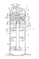
- FIG. 1 It is a longitudinal section showing a scroll type compressor in this embodiment.
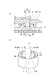
- A is the elements on larger scale near the discharge port of the fixed scroll of FIG. 1
- (b) is a perspective view which shows typically the discharge port vicinity of (a).
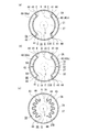
- (A)-(f) is a cross-sectional view for demonstrating the various installation states of a partition wall.
- (A)-(c) is a cross-sectional view for demonstrating the handwork which improves the rigidity of a partition wall. It is a figure which shows the effect of the sound reduction in this embodiment.
- the scroll compressor 1 of this embodiment includes an electric motor 12 and a scroll compression mechanism 2 driven by the electric motor 12 in a housing 10.
- the scroll compressor 1 compresses refrigerant such as R410C and R407C and supplies the compressed refrigerant to a refrigerant circuit such as an air conditioner or a refrigerator.
- refrigerant such as R410C and R407C
- a refrigerant circuit such as an air conditioner or a refrigerator.
- the housing 10 includes a bottomed cylindrical housing main body 101 having an open upper end, and a housing top 102 that covers an opening at the upper end of the housing main body 101.
- a suction pipe 13 for introducing a refrigerant into the housing body 101 from an accumulator (not shown) is provided on a side surface of the housing body 101.
- the housing top 102 is provided with a discharge pipe 14 that discharges the refrigerant compressed by the scroll compression mechanism 2.
- the interior of the housing 10 is partitioned into a low pressure chamber 10A and a high pressure chamber 10B by a discharge cover 25.
- the electric motor 12 includes a stator 15 and a rotor 16.
- the stator 15 is provided with a winding that generates a magnetic field when electric power is supplied through a power supply unit (not shown) attached to the side surface of the housing body 101.
- the rotor 16 includes a permanent magnet and a yoke as main elements, and a main shaft 17 is integrally coupled around the center.
- An upper bearing 18 and a lower bearing 19 that rotatably support the main shaft 17 are provided on both ends of the main shaft 17 with the electric motor 12 interposed therebetween.
- an eccentric pin 17A provided at the upper end of the main shaft 17 protrudes and is accommodated.
- the scroll compression mechanism 2 includes a fixed scroll 20 and a turning scroll 30 that revolves with respect to the fixed scroll 20.
- the fixed scroll 20 includes a fixed end plate 21 and a spiral wrap 22 erected from one surface of the fixed end plate 21.
- the fixed scroll 20 is also provided with a discharge port 23 in the fixed end plate 21.
- the discharge port 23 has an upstream port portion 23A having a circular opening shape (cavity) and a downstream port having a volume larger than that of the upstream port portion 23A.
- Part 23B The upstream port portion 23A is disposed on the upstream side in the refrigerant flow direction A, and the downstream port portion 23B is disposed on the downstream side.
- the upstream port portion 23 ⁇ / b> A communicates with a compression chamber PR formed between the fixed scroll 20 and the orbiting scroll 30 on the upstream side. Further, the downstream port portion 23 ⁇ / b> B communicates with the discharge port 27 of the discharge cover 25 that covers the upper side of the fixed scroll 20 on the downstream side.
- a partition wall 40 is provided in the downstream port portion 23B.
- the partition wall 40 is composed of partition walls 40a and 40b having the same shape and the same dimensions, each of which has an arcuate cross section.
- the partition wall 40 partitions the downstream port portion 23B into the outer region OA and the inner region IA, and changes the natural frequency of the downstream port portion 23B.
- the partition walls 40a and 40b are disposed at symmetrical positions around the center C of the downstream port portion 23B. By disposing the partition wall 40 at a symmetrical position, it is possible to reduce disturbance of the refrigerant flow in the downstream port portion 23B.
- a gap G is provided between the circumferential ends E of the partition walls 40a and 40b.
- the gap G is provided over the entire area of the partition walls 40a and 40b in the height direction, and communicates the outer region OA and the inner region IA in the radial direction.
- the refrigerant that has flowed into the downstream port portion 23B flows into the discharge port 27 of the discharge cover 25 through the refrigerant passage that continues to the outer region OA, the gap G, and the inner region IA.
- the partition wall 40 is formed integrally with the discharge cover 25, and is provided so that the tip thereof is in contact with the surface of the fixed end plate 21. The operation and effect of providing the partition wall 40 will be described later.
- the orbiting scroll 30 is also provided with a disc-shaped orbiting end plate 31 and a spiral wrap 32 erected from one surface of the orbiting end plate 31.
- a boss 34 is provided on the rear surface of the orbiting end plate 31 of the orbiting scroll 30, and a drive bush 36 is assembled to the boss 34 via a bearing.
- An eccentric pin 17A is fitted inside the drive bush 36.
- the orbiting scroll 30 is eccentrically coupled to the axis of the main shaft 17. Therefore, when the main shaft 17 rotates, the orbiting scroll 30 rotates (revolves) with the eccentric distance from the axis of the main shaft 17 as the orbiting radius.
- An Oldham ring (not shown) that restrains rotation is provided between the orbiting scroll 30 and the main shaft 17 so that the orbiting scroll 30 does not rotate while revolving.
- the compression chamber PR is formed point-symmetrically with respect to the spiral center portions (innermost peripheral portions) of the wraps 22 and 32, and the compression chamber reduces its volume as the orbiting scroll 30 turns. Gradually moved to the inner circumference. The refrigerant is compressed to the maximum at the center of the spiral.
- the compression chamber PR in FIG. 1 shows this portion.
- the volume of the compression chamber PR formed between the scrolls 20 and 30 is also reduced in the wrap height direction in the middle of the spiral. Therefore, in both the fixed scroll 20 and the orbiting scroll 30, the height of the wrap is made lower on the inner peripheral side than on the outer peripheral side, and the other end plate facing the stepped wrap is placed on the inner side from the outer peripheral side. On the circumferential side, it protrudes toward the inner surface of the end plate.
- the electric motor 12 is excited and a refrigerant is introduced into the housing 10 through the suction pipe 13.
- the electric motor 12 is energized, the main shaft 17 rotates, and the orbiting scroll 30 revolves with respect to the fixed scroll 20 accordingly.
- the refrigerant is compressed in the compression chamber PR between the orbiting scroll 30 and the fixed scroll 20, and the refrigerant introduced into the low pressure chamber 10 ⁇ / b> A in the housing 10 from the suction pipe 13 is exchanged between the orbiting scroll 30 and the fixed scroll 20. Inhaled in between.
- the refrigerant compressed in the compression chamber PR sequentially passes through the discharge port 23 of the fixed end plate 21 and the discharge port 27 of the discharge cover 25 and is discharged to the high pressure chamber 10B, and further discharged from the discharge pipe 14 to the outside. Is done. In this way, refrigerant suction, compression, and discharge are continuously performed.
- the partition wall 40 is provided in the downstream port portion 23B, thereby partitioning the internal space of the downstream port portion 23B into the outer region OA and the inner region IA. By doing so, the natural frequency in the downstream port portion 23B is changed when the partition wall 40 is not provided. By changing the natural frequency in this way, it is possible to reduce sound in an arbitrary frequency band.
- an arbitrary frequency band can be reduced by setting the length L of the partition wall 40 to 1 ⁇ 2 of the wavelength ⁇ of the sound to be reduced.
- the length L of the partition wall 40 is increased, the low frequency sound can be reduced. On the contrary, as the length of the partition wall 40 is decreased, the high frequency sound tends to be reduced.
- the length L but also the height T of the partition wall 40 is an object of tuning of the partition wall 40.
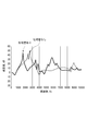
- the relationship between the frequency and the volume reduction was examined for both the compressor provided with the partition wall 40 and the compressor not provided with the partition wall 40.
- the result is shown in FIG.
- the vertical axis represents the volume reduction, and the larger the value, the greater the amount of sound reduction.
- FIG. 5 it has been found that by providing the partition wall 40 in a frequency band of 1.6 kHz, it is possible to reduce sound by about 25 dB.
- the partition wall 40 it has been found that sound reduction can be promoted even in the frequency band of 4.0 to 5.0 kHz. From the above results, it was confirmed that by providing the partition wall 40 in the downstream port portion 23B, it is possible to reduce the sound corresponding to 1.6 kHz and 4.1 kHz that cause noise.
- partition wall shape In the above, an example in which two partition walls 40a and 40b having the same shape and the same size are provided symmetrically has been described. However, the present invention is not limited to this, and various modifications can be made to the formation pattern of the partition wall 40. it can. With reference to FIG. 3, some examples are shown. For example, one gap G of the partition walls 40a and 40b can be connected to form a C-shaped partition wall 40 as shown in FIG. Thus, by increasing the length L of the arc of the partition wall 40, it is possible to reduce the sound of a lower frequency.
- the symmetrical center C 'of the partition wall 40 (40a, 40b) can also be provided in the position eccentric from the center C of the downstream port part 23B.
- the partition walls 40a and 40b from which the length of an arc differs can be used. By doing so, the sound of the frequency of a different area
- the distance from the center C to the partition walls 40a and 40b can be varied.
- the partition wall 40 can also be divided and provided in three or more (three in FIG.3 (d)).
- the partition walls 40a, 40c, 40b, and 40d can also be provided in double in the radial direction. Also in this case, the downstream port portion 23B is partitioned into a plurality of regions. That is, each of the partition walls 40a to 40d is partitioned into a radially inner region and an outer region. This is effective when the arc length L of the partition wall 40 as a whole is increased to increase the sound reduction effect.
- the partition wall 40 is not limited to being double, and the partition wall 40 may be triple or more.
- the partition wall 40 may be spiral.
- the spiral partition wall 40 partitions the downstream port portion 23 ⁇ / b> B into an inner area surrounded by the partition wall 40 in the radial direction and an outermost outermost area of the partition wall 40. Even when the partition wall 40 is formed in a spiral shape, the length L of the partition wall 40 can be increased, which is effective in reducing the sound of a lower frequency.
- the refrigerant flowing in from the upstream port portion 23A passes through the downstream port portion 23B while flowing in a spiral shape along the partition wall 40, and is discharged to the discharge port 27. It should be noted that the forms shown in FIGS. 3A to 3F can be appropriately combined.
- the partition wall 40 is not limited to an arc shape (or an elliptical arc shape), and various types of partition walls 40 such as a linear shape or a U-shape may be used. Further, when a plurality of, for example, two partition walls 40a and 40b are provided, they can be provided at asymmetric positions. In short, the form of the partition wall is not limited as long as the partition wall is tuned according to the frequency band to be reduced.
- the partition wall 40 needs to have rigidity that can counteract the pressure received from the refrigerant passing through the discharge port 23.
- the rigidity referred to here is exclusively related to the joint portion with the discharge cover 25. Therefore, in the present embodiment, as shown in FIG. 4A, ribs 41 projecting outward in the radial direction can be provided at the end portions E and E of the partition walls 40a and 40b. By providing the rib 41, the partition walls 40a and 40b are improved in rigidity against the pressure of the refrigerant from the inner region IA toward the outer side in the radial direction.
- the rib 41 has the same height as the partition wall 40 and has a uniform width in the height direction, but is not limited to this as long as the effect of improving the rigidity can be obtained.
- the rib 41 has a function of forming a diaphragm in addition to a function of improving rigidity. That is, by providing the rib 41, the refrigerant inlet / outlet 44 from the inner area IA to the outer area OA is throttled, so that the effect of reducing sound is increased.
- the rib 42 can be provided at an arbitrary position between the end portions E and E, for example, at an intermediate position. By doing so, the rigidity of the partition wall 40 is further improved, and the partition wall 50 having a length of 1/2 L is formed between the rib 41 and the rib 42, so that the sound in the high frequency range is also reduced. I can sound.
- a partition wall 43 having a corrugated cross section can also be applied as shown in FIG.
- portions corresponding to the corrugated peaks and valleys exhibit the same action as the rib 41.
- the partition wall 43 has higher rigidity.
- the partition wall 40 is not limited to be formed integrally with the discharge cover 25 as long as the downstream port portion 23B is partitioned into the outer region OA and the inner region IA.
- it may be formed integrally with the fixed end plate 21, or may be manufactured separately from the fixed end plate 21 and the discharge cover 25 and fixed to a predetermined position of the downstream port portion 23 ⁇ / b> B by an appropriate means.
- the tip of the partition wall 40 is not necessarily in contact with the fixed end plate 21, and the tip of the partition wall 40 may be separated from the fixed end plate 21 as long as the sound reduction effect by the partition wall is obtained.
Landscapes
- Engineering & Computer Science (AREA)
- Mechanical Engineering (AREA)
- General Engineering & Computer Science (AREA)
- Applications Or Details Of Rotary Compressors (AREA)
- Rotary Pumps (AREA)
Abstract
La présente invention concerne un compresseur à volute capable de réduire le bruit d'une quelconque bande de fréquence arbitraire se manifestant dans le compresseur à volute. Le présent compresseur (1) à volute comporte: une volute rotative (30) liée de façon tournante à une partie d'arbre excentrique d'un arbre principal (17); une volute fixe (20) faisant face à la volute tournante (30) pour former une chambre de compression (PR) servant à comprimer un agent frigorigène, et comportant un orifice (23) d'éjection dans une culasse fixe (21), l'orifice d'éjection servant à éjecter de l'agent frigorigène comprimé dans une chambre (10B) à haute pression; et un couvercle (25) de refoulement servant à recouvrir l'orifice (23) d'éjection. L'orifice (23) d'éjection comporte une section amont (23A) d'orifice placée du côté amont suivant la direction dans laquelle arrive l'agent frigorigène, et une section aval (23B) d'orifice placée du côté aval suivant la direction dans laquelle arrive l'agent frigorigène, la section aval d'orifice possédant une capacité supérieure à celle de la section amont d'orifice. De plus, la section aval (23B) d'orifice est caractérisée en ce qu'elle comporte une cloison (40) de subdivision servant à en subdiviser l'intérieur en une pluralité de zones, et un passage d'agent frigorigène au moyen duquel l'agent frigorigène traverse la pluralité de zones.
Priority Applications (2)
| Application Number | Priority Date | Filing Date | Title |
|---|---|---|---|
| CN201480016535.6A CN105190041B (zh) | 2013-06-27 | 2014-06-11 | 涡旋式压缩机 |
| EP14816917.0A EP3015709B1 (fr) | 2013-06-27 | 2014-06-11 | Compresseur à volute |
Applications Claiming Priority (2)
| Application Number | Priority Date | Filing Date | Title |
|---|---|---|---|
| JP2013-135496 | 2013-06-27 | ||
| JP2013135496A JP6130748B2 (ja) | 2013-06-27 | 2013-06-27 | スクロール型圧縮機 |
Publications (1)
| Publication Number | Publication Date |
|---|---|
| WO2014208029A1 true WO2014208029A1 (fr) | 2014-12-31 |
Family
ID=52141401
Family Applications (1)
| Application Number | Title | Priority Date | Filing Date |
|---|---|---|---|
| PCT/JP2014/003106 Ceased WO2014208029A1 (fr) | 2013-06-27 | 2014-06-11 | Compresseur à volute |
Country Status (4)
| Country | Link |
|---|---|
| EP (1) | EP3015709B1 (fr) |
| JP (1) | JP6130748B2 (fr) |
| CN (1) | CN105190041B (fr) |
| WO (1) | WO2014208029A1 (fr) |
Families Citing this family (5)
| Publication number | Priority date | Publication date | Assignee | Title |
|---|---|---|---|---|
| CN110657097B (zh) * | 2018-06-29 | 2024-08-23 | 谷轮环境科技(苏州)有限公司 | 用于压缩机中排气阀的阻尼装置、排气阀组件和压缩机 |
| US11493040B2 (en) | 2018-06-29 | 2022-11-08 | Emerson Climate Technologies (Suzhou) Co., Ltd. | Damping apparatus for exhaust valve in compressor, exhaust valve assembly, and compressor |
| CN111441951B (zh) * | 2019-01-17 | 2024-07-26 | 谷轮环境科技(苏州)有限公司 | 压缩机 |
| CN115750372B (zh) * | 2022-12-12 | 2026-04-17 | 珠海格力节能环保制冷技术研究中心有限公司 | 消音组件和涡旋压缩机 |
| CN117703717B (zh) * | 2024-02-05 | 2024-05-03 | 亚新科智能汽车技术(仪征)有限公司 | 一种具有进气消音功能的空气压缩机 |
Citations (6)
| Publication number | Priority date | Publication date | Assignee | Title |
|---|---|---|---|---|
| JPH0482391U (fr) | 1990-11-29 | 1992-07-17 | ||
| JPH06307356A (ja) * | 1993-04-26 | 1994-11-01 | Matsushita Electric Ind Co Ltd | スクロール圧縮機 |
| US5921761A (en) * | 1997-04-17 | 1999-07-13 | Copeland Corporation | Scroll machine with discharge duct |
| JP2001132666A (ja) * | 1999-11-09 | 2001-05-18 | Hitachi Ltd | 容積形圧縮機 |
| US20090232670A1 (en) * | 2005-08-29 | 2009-09-17 | Heng-Yi Lai | Compressor muffler |
| JP2012122376A (ja) * | 2010-12-07 | 2012-06-28 | Mitsubishi Heavy Ind Ltd | スクロール圧縮機 |
Family Cites Families (4)
| Publication number | Priority date | Publication date | Assignee | Title |
|---|---|---|---|---|
| US5474431A (en) * | 1993-11-16 | 1995-12-12 | Copeland Corporation | Scroll machine having discharge port inserts |
| JPH08319963A (ja) * | 1995-03-22 | 1996-12-03 | Mitsubishi Electric Corp | スクロール圧縮機 |
| CN202417950U (zh) * | 2011-12-15 | 2012-09-05 | 上海日立电器有限公司 | 一种用于涡旋压缩机的排气装置 |
| CN202937456U (zh) * | 2012-09-21 | 2013-05-15 | 珠海格力电器股份有限公司 | 具有消音功能的高低压分隔板及涡旋压缩机 |
-
2013
- 2013-06-27 JP JP2013135496A patent/JP6130748B2/ja active Active
-
2014
- 2014-06-11 CN CN201480016535.6A patent/CN105190041B/zh active Active
- 2014-06-11 WO PCT/JP2014/003106 patent/WO2014208029A1/fr not_active Ceased
- 2014-06-11 EP EP14816917.0A patent/EP3015709B1/fr active Active
Patent Citations (6)
| Publication number | Priority date | Publication date | Assignee | Title |
|---|---|---|---|---|
| JPH0482391U (fr) | 1990-11-29 | 1992-07-17 | ||
| JPH06307356A (ja) * | 1993-04-26 | 1994-11-01 | Matsushita Electric Ind Co Ltd | スクロール圧縮機 |
| US5921761A (en) * | 1997-04-17 | 1999-07-13 | Copeland Corporation | Scroll machine with discharge duct |
| JP2001132666A (ja) * | 1999-11-09 | 2001-05-18 | Hitachi Ltd | 容積形圧縮機 |
| US20090232670A1 (en) * | 2005-08-29 | 2009-09-17 | Heng-Yi Lai | Compressor muffler |
| JP2012122376A (ja) * | 2010-12-07 | 2012-06-28 | Mitsubishi Heavy Ind Ltd | スクロール圧縮機 |
Non-Patent Citations (1)
| Title |
|---|
| See also references of EP3015709A4 * |
Also Published As
| Publication number | Publication date |
|---|---|
| CN105190041B (zh) | 2017-06-09 |
| EP3015709B1 (fr) | 2017-03-01 |
| EP3015709A1 (fr) | 2016-05-04 |
| EP3015709A4 (fr) | 2016-06-22 |
| CN105190041A (zh) | 2015-12-23 |
| JP6130748B2 (ja) | 2017-05-17 |
| JP2015010519A (ja) | 2015-01-19 |
Similar Documents
| Publication | Publication Date | Title |
|---|---|---|
| JP6130748B2 (ja) | スクロール型圧縮機 | |
| JP6187267B2 (ja) | 電動圧縮機 | |
| JP6943215B2 (ja) | 電動圧縮機 | |
| JP2009030469A (ja) | スクロール圧縮機 | |
| JP6147605B2 (ja) | 圧縮機 | |
| JP6130642B2 (ja) | 圧縮機 | |
| JP5758112B2 (ja) | スクロール圧縮機 | |
| JP6332336B2 (ja) | スクリュー圧縮機 | |
| WO2003064859A1 (fr) | Compresseur ferme | |
| JP5951456B2 (ja) | スクロール型圧縮機 | |
| JP2021161942A (ja) | スクロール型圧縮機 | |
| JP4844642B2 (ja) | スクロール圧縮機 | |
| KR20180104871A (ko) | 로터리 압축기 | |
| JP2009167983A (ja) | スクロール圧縮機 | |
| US12473918B2 (en) | Scroll compressor | |
| JP5179955B2 (ja) | 容積形圧縮機 | |
| JP2014118862A (ja) | 回転式圧縮機 | |
| WO2017183367A1 (fr) | Compresseur rotatif | |
| JP5916419B2 (ja) | スクロール圧縮機 | |
| US20240263632A1 (en) | Scroll compressor | |
| KR20190106329A (ko) | 로터리 압축기 | |
| JP2009191845A (ja) | 圧縮機 | |
| JP2019178677A (ja) | 圧縮機 |
Legal Events
| Date | Code | Title | Description |
|---|---|---|---|
| WWE | Wipo information: entry into national phase |
Ref document number: 201480016535.6 Country of ref document: CN |
|
| 121 | Ep: the epo has been informed by wipo that ep was designated in this application |
Ref document number: 14816917 Country of ref document: EP Kind code of ref document: A1 |
|
| REEP | Request for entry into the european phase |
Ref document number: 2014816917 Country of ref document: EP |
|
| WWE | Wipo information: entry into national phase |
Ref document number: 2014816917 Country of ref document: EP |
|
| NENP | Non-entry into the national phase |
Ref country code: DE |