WO2014208140A1 - Station de base sans fil, terminal d'utilisateur et méthode de communication sans fil - Google Patents
Station de base sans fil, terminal d'utilisateur et méthode de communication sans fil Download PDFInfo
- Publication number
- WO2014208140A1 WO2014208140A1 PCT/JP2014/056035 JP2014056035W WO2014208140A1 WO 2014208140 A1 WO2014208140 A1 WO 2014208140A1 JP 2014056035 W JP2014056035 W JP 2014056035W WO 2014208140 A1 WO2014208140 A1 WO 2014208140A1
- Authority
- WO
- WIPO (PCT)
- Prior art keywords
- user
- user terminal
- base station
- transmission power
- terminal
- Prior art date
- Legal status (The legal status is an assumption and is not a legal conclusion. Google has not performed a legal analysis and makes no representation as to the accuracy of the status listed.)
- Ceased
Links
Images


Classifications
-
- H—ELECTRICITY
- H04—ELECTRIC COMMUNICATION TECHNIQUE
- H04W—WIRELESS COMMUNICATION NETWORKS
- H04W72/00—Local resource management
- H04W72/04—Wireless resource allocation
- H04W72/044—Wireless resource allocation based on the type of the allocated resource
- H04W72/0473—Wireless resource allocation based on the type of the allocated resource the resource being transmission power
-
- H—ELECTRICITY
- H04—ELECTRIC COMMUNICATION TECHNIQUE
- H04W—WIRELESS COMMUNICATION NETWORKS
- H04W52/00—Power management, e.g. Transmission Power Control [TPC] or power classes
- H04W52/04—Transmission power control [TPC]
- H04W52/18—TPC being performed according to specific parameters
- H04W52/24—TPC being performed according to specific parameters using SIR [Signal to Interference Ratio] or other wireless path parameters
-
- H—ELECTRICITY
- H04—ELECTRIC COMMUNICATION TECHNIQUE
- H04W—WIRELESS COMMUNICATION NETWORKS
- H04W52/00—Power management, e.g. Transmission Power Control [TPC] or power classes
- H04W52/04—Transmission power control [TPC]
- H04W52/30—Transmission power control [TPC] using constraints in the total amount of available transmission power
- H04W52/34—TPC management, i.e. sharing limited amount of power among users or channels or data types, e.g. cell loading
- H04W52/346—TPC management, i.e. sharing limited amount of power among users or channels or data types, e.g. cell loading distributing total power among users or channels
-
- H—ELECTRICITY
- H04—ELECTRIC COMMUNICATION TECHNIQUE
- H04W—WIRELESS COMMUNICATION NETWORKS
- H04W72/00—Local resource management
- H04W72/20—Control channels or signalling for resource management
- H04W72/23—Control channels or signalling for resource management in the downlink direction of a wireless link, i.e. towards a terminal
Definitions
- the present invention relates to a radio base station, a user terminal, and a radio communication method in a next generation mobile communication system.
- CDMA Code Division Multiple Access
- UMTS Universal Mobile Telecommunications System
- W-CDMA Wideband Code Division Multiple Access
- OFDMA Orthogonal Frequency Division Multiple Access
- FRA Full Radio Access
- NOMA interference cancellation
- OFDMA Interference Cancellation
- downlink signals for a plurality of user terminals are superposed on the same radio resource allocated by OFDMA, and transmitted with different transmission power according to the channel gain of each user terminal.
- the downlink signal for the other terminal is canceled by SIC (Successive Interference Cancellation) or the like, so that the downlink signal for the own terminal is appropriately extracted.
- transmission modulation (Fast TPC) is used in W-CDMA, and adaptive modulation and coding (AMC) is used to adaptively adjust the modulation method and coding rate in LTE. Is used.
- FRA transmission power allocation and adaptive modulation and coding
- MUPA transmission power allocation and adaptive modulation and coding
- the present invention has been made in view of the above points, and an object of the present invention is to provide a radio base station, a user terminal, and a radio communication method capable of realizing link adaptation optimal for a future radio communication system.
- the radio base station of the present invention selects a user terminal from each user group determined according to the channel gain of each user terminal, and uses an arbitrary radio resource with transmission power fixedly assigned to each user group.
- the transmission power since the transmission power is fixed according to the user group, the transmission power does not fluctuate while the user terminals belong to the same user group. Therefore, it is possible to suppress selection of an inappropriate modulation scheme and encoding scheme due to transmission power control flicker. Moreover, since a user is selected from each user group and a user set is determined, the amount of calculation when determining a user set can be reduced as compared with a configuration in which a user set is determined from all users.
- FIG. 2 is an explanatory diagram of NOMA (non-orthogonal multiple access) in the downlink.
- FIG. 2 shows a case where the user terminal UE1 is located near the radio base station BS and the user terminal UE2 is located far from the radio base station BS within the coverage area of the radio base station BS.
- the path loss of the downlink signal from the radio base station BS to each user terminal UE increases as the distance from the radio base station BS increases. For this reason, the reception SINR of the user terminal UE2 far from the radio base station BS is lower than the reception SINR of the user terminal UE1 near the radio base station BS.
- a plurality of user terminals UE are non-orthogonally multiplexed with respect to the same radio resource by changing transmission power according to channel gain (for example, reception SINR, RSRP, etc.), path loss, and the like.
- channel gain for example, reception SINR, RSRP, etc.
- path loss path loss
- downlink signals for the user terminals UE1 and UE2 are multiplexed on the same radio resource with different transmission powers.
- a relatively small transmission power is assigned to the downlink signal for the user terminal UE1 having a high reception SINR
- a relatively large transmission power is assigned to the downlink signal for the user terminal UE2 having a low reception SINR.
- the downlink signal for the terminal is extracted by removing the interference signal from the received signal by SIC, which is a successive interference canceller type signal separation method.
- SIC which is a successive interference canceller type signal separation method.
- the downlink signal for another terminal having higher transmission power than the own terminal non-orthogonally multiplexed on the same radio resource becomes an interference signal.
- the downlink signal for the own terminal is extracted by removing, from the received signal, the downlink signal for the other terminal having higher transmission power than the own terminal.
- the downlink signal for the user terminal UE2 is transmitted with larger transmission power than the downlink signal for the user terminal UE1.
- the user terminal UE1 close to the radio base station BS receives not only the downlink signal for the terminal itself but also the downlink signal for the user terminal UE2 non-orthogonally multiplexed on the same radio resource as an interference signal.
- the user terminal UE1 extracts and properly decodes the downlink signal for the user terminal by removing the downlink signal for the user terminal UE2 by SIC.
- the downlink signal for the user terminal UE1 is transmitted with a smaller transmission power than the downlink signal for the user terminal UE2. For this reason, the user terminal UE2 far from the radio base station BS can appropriately receive the downlink signal for the own terminal, ignoring the downlink signal for the user terminal UE1 non-orthogonally multiplexed on the same radio resource. Since the user terminal UE2 can ignore the interference due to the downlink signal with respect to the user terminal UE1, the user terminal UE2 extracts and appropriately decodes the downlink signal with respect to the own terminal without performing interference removal by the SIC.
- NOMA when NOMA is applied in the downlink, it is possible to multiplex a plurality of user terminals UE1 and UE2 having different channel gains (reception SINR, etc.) for the same radio resource, thereby improving frequency utilization efficiency. it can.
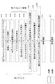
- FIG. 3 is a flowchart for explaining NOMA transmission processing.
- each user terminal UE receives a reference signal from the radio base station BS, and estimates a channel gain based on this reference signal.
- Each user terminal UE feeds back the channel gain to the radio base station BS (step ST01).
- CSI-RS Channel State Information Reference Signal
- DM-RS DeModulation Reference Signal
- CRS Cell-Specific Reference Signal
- the radio base station BS selects one candidate user set (candidate user set) from all users belonging to the coverage area for each subband (step ST02).
- the candidate user set indicates a combination of user terminal candidates that are non-orthogonal-multiplexed to subbands.
- the total number of candidate user sets for each subband is expressed by the following equation (1), where N max is the number of non-orthogonal multiplexed users and M is the total number of user terminals UE belonging to the coverage area. Note that the following series of arithmetic processing (steps ST03 to ST06) is performed for all candidate user sets (Exhaustive search).
- the radio base station BS calculates transmission power allocated to the user terminals UE of each candidate user set based on the channel gain fed back from each user terminal UE (step ST03).
- the radio base station BS calculates SINR (SINR for scheduling) of each user terminal UE assumed under application of non-orthogonal multiplexing based on transmission power (step ST04).
- the radio base station apparatus BS obtains a block error rate (BLER: Block Error Rate) of the MCS set from the SINR, and calculates the PF metric throughput of each user terminal UE (step ST05).
- BLER Block Error Rate
- the radio base station BS calculates a PF scheduling metric for the candidate user set from the throughput and average throughput of each user terminal (step ST06).
- the PF scheduling metric M sj, b is expressed by the following equation (2), where T k is the average throughput and R k, b is the throughput. Note that the PF scheduling metric M sj, b indicates that it is the PF scheduling metric of the jth candidate user set in the bth subband. Moreover, k has shown that it is the kth user terminal in a candidate user set.
- the radio base station BS selects a user set that maximizes the PF scheduling metric in each subband (step ST07). And the downlink signal with respect to each user terminal UE which comprises a user set is allocated to the same subband, and non-orthogonal multiplexing is carried out with different transmission power.
- the radio base station BS calculates an average SINR for each subband (step ST08), and selects a common MCS for the subband user terminals (step ST09).
- the radio base station BS transmits a downlink signal with different transmission power to each user terminal UE of the user set (step ST10).
- each user terminal UE selected as a user set by the base station apparatus BS receives not only a downlink signal for the terminal itself but also a downlink signal for other terminals that are non-orthogonally multiplexed on the same radio resource (step ST11). ). And each user terminal UE removes the downlink signal with respect to the other terminal whose channel gain is lower than that of its own terminal and whose transmission power is large by SIC, and extracts (separates) the signal for its own terminal. In this case, a downlink signal for another terminal having a channel gain higher than that of the own terminal and having a small transmission power is ignored because it does not become an interference signal.
- the calculation process of the PF scheduling metric described above is performed for all candidate user sets. For this reason, when the number of user terminals and the number of transmission beams to be scheduled increases, the amount of computation for the full search becomes enormous. Specifically, the calculation amount of the full search increases exponentially in proportion to the number of candidate user sets.
- the MCS selection threshold is controlled according to ACK / NACK fed back by HARQ (Hybrid ARQ) process using OLLA (Outer-Loop Link Adaptation)
- HARQ Hybrid ARQ
- OLLA Outer-Loop Link Adaptation
- the present inventors have arrived at the present invention in order to reduce the amount of calculation for full search when determining a user set and to suppress fluctuations in power control. That is, the gist of the present invention is to reduce the total number of candidate user sets by defining a plurality of user groups according to the channel gain of the user terminal and selecting a user terminal from each group. In addition, the transmission power is fixedly assigned to each user group, thereby suppressing the fluctuation of the transmission power and improving the MCS control accuracy. With such a configuration, it is possible to realize optimum link adaptation.
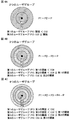
- FIG. 4 a method for grouping user terminals and assigning transmission power will be described.
- a case where one user terminal is selected from each of a plurality of user groups and non-orthogonal multiplexing is performed is shown.
- a case will be described in which two user terminals are non-orthogonal multiplexed for one radio resource (resource block or the like), but three or more user terminals are non-orthogonally multiplexed for one radio resource. Also good.
- the grouping and transmission power allocation methods are merely examples, and are not limited to the following configurations.
- FIG. 4A shows a case where user terminals in a coverage area (cell) are grouped into first and second user groups.
- the user terminals are grouped according to the magnitude of the channel gain of each user terminal in the coverage area.
- CQI Channel Quality Indicator
- the CQI may be an instantaneous or long-term average CQI, or a narrowband or wideband CQI.
- the channel gain may be an index indicating the reception quality of the channel, and may be, for example, reception SINR or RSRP.
- Transmission power is fixedly assigned to the first and second user groups by the radio base station.
- a first transmission power P1 is assigned to the first user group, and a second transmission power P2 obtained by subtracting the first transmission power P1 from the total transmission power P is assigned to the second user group.
- a relatively small transmission power P1 is assigned to the first user group near the center of the coverage area, and a relatively large transmission power P2 is assigned to the second user group far from the coverage area.
- the total transmission power P for an arbitrary radio resource is distributed at such a ratio that it is small for a user group with a large channel gain and large for a user group with a small channel gain.
- one user terminal is selected from each of the first and second user groups, and is non-orthogonally multiplexed on the same radio resource with different transmission powers P1 and P2.
- FIG. 4B shows a case where user terminals in a coverage area (cell) are grouped into first to third user groups.
- the user terminal whose CQI is larger than the first threshold is the first user group
- the user terminal whose CQI is equal to or smaller than the second threshold is the second user group
- the CQI is equal to or smaller than the first threshold and the second threshold.
- Larger user terminals belong to the third user group, respectively. That is, the areas of the first user group, the third user group, and the second user group are formed concentrically from the center of the coverage area toward the outside.
- the first transmission power P1 is assigned to the first user group, and the second transmission power P2 obtained by subtracting the first transmission power P1 from the total transmission power P is assigned to the second user group.
- the total transmission power P is assigned to the third user group.
- one user terminal is selected from each of the first and second user groups, and is non-orthogonally multiplexed onto the same radio resource with different transmission powers P1 and P2.
- one user terminal is selected from the third user group, and is orthogonally multiplexed with transmission power P on a radio resource different from that of the first and second user groups.
- FIG. 4C shows a case where user terminals in a coverage area (cell) are grouped into first to fourth user groups.
- user terminals whose CQI is larger than the first threshold belong to the first user group
- user terminals whose CQI is equal to or smaller than the second threshold and larger than the third threshold belong to the second user group.
- user terminals whose CQI is equal to or smaller than the first threshold and greater than the second threshold belong to the third user group
- user terminals whose CQI is equal to or smaller than the third threshold belong to the fourth user group. That is, the areas of the first user group, the third user group, the second user group, and the fourth user group are formed concentrically from the center of the coverage area toward the outside.
- the first transmission power P1 is assigned to the first user group, and the second transmission power P2 obtained by subtracting the first transmission power P1 from the total transmission power P is assigned to the second user group.
- a third transmission power P3 is assigned to the third user group, and a fourth transmission power P4 obtained by subtracting the third transmission power P3 from the total transmission power P is assigned to the fourth user group.
- one user terminal is selected from each of the first and second user groups, and is non-orthogonally multiplexed onto the same radio resource with different transmission powers P1 and P2.
- one user terminal is selected from each of the third and fourth user groups, and is non-orthogonal-multiplexed to radio resources different from the first and second user groups with different transmission powers P3 and P4.
- user terminals of user groups as far away as possible are selected and non-orthogonal multiplexed.
- the user group that is non-orthogonally multiplexed is not limited to the above configuration.
- the user terminals of the first and fourth user groups may be non-orthogonal multiplexed
- the user terminals of the second and third user groups may be non-orthogonal multiplexed.
- the user groups that are orthogonally multiplexed are not limited to configurations that are multiplexed on different radio resources.
- the user terminals of the first and second user groups are non-orthogonal multiplexed on the same radio resource
- the user terminals of the third user group are code-multiplexed on this radio resource. Good.
- N max is the number of non-orthogonal users
- M is the total number of user terminals UE belonging to the coverage area
- R is the number of user groups.
- the total number of user terminals in the coverage area is 10 to select two user terminals.
- the number of candidate user sets is 45 ( 10 C 2 ).
- the candidate user set number it is sufficient select a user terminal one by one from each user group, the candidate user set number to 25 (5 C 1 ⁇ 5 C 1) Become. For this reason, it is possible to reduce the number of candidate user sets and reduce the amount of calculation for full search when determining user sets.
- transmission power is fixedly assigned to each user group, transmission power does not fluctuate while user terminals belong to the same user group. Therefore, even when OLLA is applied in MCS control, selection of an inappropriate modulation scheme and coding scheme can be avoided, and MCS control accuracy can be improved.
- the determination of which user group a user terminal belongs to may be determined on the user terminal side or on the radio base station side.
- FIG. 5A shows an example when the user terminal side determines the user group to which the own terminal belongs.
- FIG. 5B shows an example of determining a user group to which each user terminal belongs on the radio base station side.
- a relationship table indicating the relationship between the magnitude of the channel gain and the user group is notified from the radio base station to the user terminal (step ST21).
- the relationship table is stored in the user terminal (step ST22). Since the transmission power is fixedly set for the user group, not only the channel gain and the user group but also the channel gain and the power value of the transmission power are associated by the relation table.
- the relationship table only needs to be able to determine which user group the user terminal belongs to, and may indicate the relationship between the magnitude of the channel gain and the allocation of transmission power. Further, when the relationship table is stored in advance in each user terminal, the process of step ST21-22 can be omitted.
- a reference signal is transmitted from the radio base station to the user terminal (step ST23).
- the magnitude of the channel gain is estimated from the reference signal, and the user group to which the terminal belongs and the power value of the downlink signal are determined with reference to the relation table (step ST24).
- Group information indicating the user group determined by the user terminal is fed back from the user terminal to the radio base station (step ST25).
- the group information may be a user group or a power value assigned to each user terminal.
- the radio base station performs scheduling based on the group information fed back from the user terminal (step ST26). That is, a user set that maximizes the PF scheduling metric is determined from a plurality of candidate user sets in a state in which the amount of calculation by the full search is suppressed by grouping. And each user terminal which comprises a user set is non-orthogonal-multiplexed, and a downlink signal is transmitted with respect to each user terminal from a wireless base station with different transmission power (step ST27).
- the user terminal since the user terminal determines the power value assigned to the own terminal, it is not necessary to notify the power value from the radio base station to the user terminal, and the communication procedure can be simplified.
- the radio base station may prioritize the transmission power determined by the radio base station over the transmission power requested from the user terminal.
- a reference signal is transmitted from the radio base station to the user terminal (step ST31).
- the user terminal estimates the magnitude of the channel gain from the reference signal (step ST32), and the channel gain is fed back from the user terminal to the radio base station (step ST33).
- the user group to which the user terminal belongs and the power value of the downlink signal are determined based on the channel gain fed back from the user terminal, and scheduling is performed (step ST34). That is, a user set that maximizes the PF scheduling metric is determined from a plurality of candidate user sets in a state in which the amount of calculation by the full search is suppressed by grouping.
- the power value assigned to the user terminal is transmitted from the radio base station to the user terminal (step ST35).
- each user terminal which comprises a user set is non-orthogonal-multiplexed, and a downlink signal is transmitted with respect to each user terminal from a wireless base station with different transmission power (step ST36).
- a group index indicating a user group may be notified instead of the configuration in which the power value is transmitted from the radio base station to the user terminal.
- the radio base station notifies the user terminal of a relationship table indicating the relationship between the user group index and transmission power allocation prior to step ST31. .
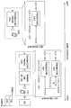
- FIG. 6 is a schematic configuration diagram of the radio communication system according to the present embodiment.
- the radio communication system shown in FIG. 6 is a system including, for example, an LTE system or an LTE-A (LTE-Advanced) system.
- This wireless communication system may be called IMT-Advanced, or may be called 4G, FRA (Future Radio Access).
- the radio communication system 1 shown in FIG. 6 includes a radio base station 10 (10A, 10B) and a plurality of user terminals 20 (20A, 20B) communicating with the radio base station 10.
- the radio base station 10 is connected to the upper station apparatus 30, and the upper station apparatus 30 is connected to the core network 40.
- Each user terminal 20 can communicate with the radio base station 10 in the cells C1 and C2.
- the upper station device 30 includes, for example, an access gateway device, a radio network controller (RNC), a mobility management entity (MME), and the like, but is not limited thereto.
- the radio base station 10 may be an eNodeB (eNB) that forms a macro cell, or may be any of an RRH (Remote Radio Head), a femto base station, a pico base station, or the like that forms a small cell. .
- the radio base station 10 may also be called a transmission / reception point.
- Each user terminal 20 is a terminal that supports various communication schemes such as LTE and LTE-A, and may include not only a mobile communication terminal but also a fixed communication terminal.
- OFDMA Orthogonal Frequency Division Multiple Access
- NOMA Non-Orthogonal Multiple Access
- SC-FDMA Single Carrier Frequency Division Multiple for uplink
- OFDMA is a multicarrier transmission scheme that divides a transmission band into subbands and orthogonally multiplexes user terminals
- NOMA is a multicarrier transmission scheme that non-orthogonally multiplexes user terminals 20 with different transmission power for each subband.
- SC-FDMA is a single carrier transmission scheme in which user terminals 20 are assigned to continuous radio resources in the frequency direction.
- a downlink shared data channel shared by each user terminal 20
- a downlink L1 / L2 control channel (PDCCH, PCFICH, PHICH, extended PDCCH), broadcast channel (PBCH) or the like
- PDSCH Physical Downlink Shared Channel
- PDSCH and PUSCH scheduling information is transmitted by PDCCH (Physical Downlink Control Channel) and EPDCCH (Enhanced Physical Downlink Control Channel).
- the number of OFDM symbols used for PDCCH is transmitted by PCFICH (Physical Control Format Indicator Channel).
- the HARQ ACK / NACK for PUSCH is transmitted by PHICH (Physical Hybrid-ARQ Indicator Channel).
- an uplink shared channel (PUSCH), an uplink control channel (PUCCH), a random access channel (PRACH), etc. shared by the user terminals 20 are used as the uplink communication channel.
- User data and higher-level control information are transmitted by PUSCH (Physical Uplink Shared Channel).
- Downlink channel state information (CSI: Channel State Information), ACK / NACK, etc. are transmitted by PUCCH (Physical Uplink Control Channel) or PUSCH.
- FIG. 7 is a block diagram showing a configuration example of the radio base station according to the present embodiment.
- the radio base station 10 includes a transmission / reception antenna 101, an amplifier unit 102, a transmission / reception unit (transmission unit, reception unit) 103, a baseband signal processing unit 104, a call processing unit 105, and a transmission path interface 106. Yes.
- User data transmitted from the radio base station 10 to the user terminal 20 via the downlink is input from the higher station apparatus 30 to the baseband signal processing unit 104 via the transmission path interface 106.
- the baseband signal processing unit 104 performs PDCP layer processing, user data division / combination, RLC (Radio Link Control) retransmission control transmission processing such as RLC layer transmission processing, MAC ( Medium Access Control) retransmission control, for example, HARQ transmission processing, scheduling, transmission format selection, channel coding, IFFT (Inverse Fast Fourier Transform) processing, precoding processing is performed, and the data is transferred to each transmitting / receiving section 103.
- transmission processing such as channel coding and inverse fast Fourier transform is performed on the downlink control data, and the data is transferred to each transmission / reception section 103.
- Each transmission / reception unit 103 converts the baseband signal output by precoding from the baseband signal processing unit 104 for each antenna to a radio frequency band.
- the amplifier unit 102 amplifies the frequency-converted radio frequency signal and transmits the amplified signal using the transmission / reception antenna 101.
- each transmitting / receiving antenna 101 receives data transmitted from the user terminal 20 to the radio base station 10 via the uplink.
- the amplifier unit 102 amplifies the radio frequency signal input from each transmission / reception antenna 101 and sends the amplified signal to each transmission / reception unit 103.
- the amplified radio frequency signal is frequency-converted by each transmission / reception unit 103 to be converted into a baseband signal and input to the baseband signal processing unit 104.
- the baseband signal processing unit 104 performs FFT (Fast Fourier Transform) processing, IDFT (Inverse Discrete Fourier Transform) processing, error correction decoding, and MAC retransmission control reception processing on user data included in the input baseband signal.
- FFT Fast Fourier Transform
- IDFT Inverse Discrete Fourier Transform
- error correction decoding error correction decoding
- MAC retransmission control reception processing user data included in the input baseband signal.
- the RLC layer and the PDCP layer are received and transferred to the upper station apparatus 30 via the transmission path interface 106.
- the call processing unit 105 performs call processing such as communication channel setting and release, state management of the radio base station 10, radio resource management, and the like.
- FIG. 8 is a block diagram showing a configuration example of the user terminal according to the present embodiment.
- the user terminal 20 includes a plurality of transmission / reception antennas 201, an amplifier unit 202, a transmission / reception unit (reception unit) 203, a baseband signal processing unit 204, and an application unit 205.
- Downlink data is received by a plurality of transmission / reception antennas 201 and input to an amplifier unit 202.
- the amplifier unit 202 amplifies the radio frequency signal input from each transmission / reception antenna 201 and sends the amplified signal to each transmission / reception unit 203.
- the radio frequency signal is converted into a baseband signal by each transmission / reception unit 203 and input to the baseband signal processing unit 204.
- the baseband signal processing unit 204 performs FFT processing, error correction decoding, retransmission control reception processing, and the like on the baseband signal.
- User data included in the downlink data is transferred to the application unit 205.
- the application unit 205 performs processing related to layers higher than the physical layer and the MAC layer. Also, broadcast information in the downlink data is also transferred to the application unit 205.
- uplink user data is input from the application unit 205 to the baseband signal processing unit 204.
- the baseband signal processing unit 204 performs retransmission control (H-ARQ (Hybrid ARQ)) transmission processing, channel coding, precoding, DFT processing, IFFT processing, and the like on the input user data, and performs each transmission / reception
- the data is transferred to the unit 203.
- Each transmitting / receiving unit 203 converts the baseband signal output from the baseband signal processing unit 204 into a radio frequency band.
- the amplifier unit 202 amplifies the frequency-converted radio frequency signal and transmits the amplified signal using the transmitting / receiving antenna 201.
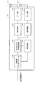
- FIG. 9 is a block diagram illustrating a configuration example of a baseband signal processing unit included in the radio base station and the user terminal according to the present embodiment. Although only a part of the configuration is shown in FIG. 9, it is assumed that the radio base station 10 and the user terminal 20 have a necessary configuration without shortage.
- the radio base station 10 includes a scheduling unit (control unit) 301, a downlink control information generation unit 302, a downlink control information encoding / modulation unit 303, a downlink transmission data generation unit 304, and a downlink transmission data encoding.
- a modulation unit 305, a downlink reference signal generation unit 306, and a downlink channel multiplexing unit 307 are provided.
- the scheduling unit 301 selects the user terminal 20 from each user group determined according to the channel gain of each user terminal 20, and determines a user set that is orthogonally multiplexed to an arbitrary radio resource.
- group information fed back from the user terminal 20 is received by the transmission / reception unit 103 (see FIG. 7).
- the scheduling unit 301 determines a user group to which each user terminal 20 belongs based on the group information.
- the group information may be information that can specify the user group to which each user terminal 20 belongs, and may be a user group or a power value assigned to each user terminal 20.
- the scheduling unit 301 recognizes the user group to which each user terminal 20 belongs based on the channel gain.
- the channel gain is not limited as long as it indicates the reception quality of the channel, and may be CQI, reception SINR, RSRP, an instantaneous value, or a long-term average value.
- the scheduling unit 301 determines the user group to which the user terminal 20 belongs by comparing the magnitude of the channel gain fed back from each user terminal 20 with a predetermined threshold.
- the scheduling unit 301 selects the user terminal 20 from each user group to create a plurality of candidate user sets, and determines a user set that maximizes the PF scheduling metric from the plurality of candidate user sets. And the downlink signal with respect to each user terminal 20 of this user set is allocated to the same radio
- the scheduling unit 301 assigns transmission power fixedly determined for each user group to each user terminal 20 that is non-orthogonal-multiplexed for each radio resource. At this time, the scheduling unit 301 reduces the total transmission power for an arbitrary radio resource to a user group to which the user terminal 20 having a large channel gain belongs, and to a user group to which the user terminal 20 having a large channel gain belongs. Allocate by ratio. Also, the scheduling section 301 determines the downlink data coding rate and modulation scheme based on the channel state information from the user terminal 20.
- the scheduling unit 301 performs non-orthogonal multiplexing for each user terminal 20 selected as the same user set, and orthogonally multiplexes each user terminal 20 selected as a different user set (see FIGS. 4B and 4C). In this way, the scheduling unit 301 schedules the user terminals 20 in the user group.
- the downlink control information generation unit 302 generates user terminal-specific downlink control information (DCI) transmitted on the PDCCH.
- the downlink control information is output to the downlink control information encoding / modulating section 303.
- the downlink control information encoding / modulating section 303 performs channel encoding and modulation of the downlink control information.
- the modulated downlink control information is output to downlink channel multiplexing section 307.
- the user terminal-specific downlink control information includes DL assignment (DL assignment), which is PDSCH assignment information, UL grant (UL grant), which is PUSCH assignment information, and the like. Further, the downlink control information includes control information for requesting CSI feedback to each user terminal 20, information necessary for reception processing of non-orthogonal multiplexed signals, and the like. For example, when grouping is determined on the radio base station 10 side (see FIG. 5B), information (power value or group index) on the transmission power of the downlink signal of the user terminal 20 may be included in the downlink control information. Good. However, the information regarding the transmission power of the downlink signal may be included in higher control information notified by higher layer signaling (RRC signaling or the like).
- RRC signaling higher layer signaling
- the downlink transmission data generation unit 304 generates downlink user data for each user terminal 20.
- the downlink user data generated by the downlink transmission data generation unit 304 is output to the downlink transmission data encoding / modulation unit 305 as downlink transmission data transmitted on the PDSCH together with the upper control information.
- the downlink transmission data encoding / modulation section 305 performs channel encoding and modulation on the downlink transmission data for each user terminal 20.
- the downlink transmission data is output to the downlink channel multiplexing unit 307.
- the downlink reference signal generation unit 306 generates downlink reference signals (CRS, CSI-RS, DM-RS, etc.).
- the downlink reference signal is output to the downlink channel multiplexing unit 307.
- the downlink channel multiplexing unit 307 combines downlink control information, downlink reference signals, and downlink transmission data (including higher control information) to generate a downlink signal. Specifically, the downlink channel multiplexing unit 307 transmits downlink signals addressed to the plurality of user terminals 20 selected by the scheduling unit 301 with a predetermined transmission power according to the scheduling information notified from the scheduling unit 301. Thus, non-orthogonal multiplexing is performed. The downlink signal generated by the downlink channel multiplexing unit 307 is transmitted toward the user terminal 20 through various transmission processes.
- the user terminal 20 includes a downlink control information reception unit 401, a channel estimation unit (estimation unit) 402, a user group determination unit 403, a feedback unit 404, an interference removal unit 405, and a downlink transmission data reception unit 406.
- the downlink signal transmitted from the radio base station 10 is separated into downlink control information, downlink transmission data (including higher control information), and a downlink reference signal through various reception processes.
- the downlink control information is input to the downlink control information reception unit 401, the downlink transmission data is input to the downlink transmission data reception unit 406 via the interference removal unit 405, and the downlink reference signal is input to the channel estimation unit 402.
- the downlink control information receiving unit 401 demodulates the downlink control information and outputs it to the channel estimation unit 402, the feedback unit 404, the interference removal unit 405, and the like.
- the channel estimation unit 402 estimates a channel based on the downlink reference signal and acquires a channel gain.
- the user group determination unit 403 determines the user group to which the own terminal belongs based on the magnitude of the channel gain. Also, the user group determination unit 403 determines the power value of transmission power allocated to the own terminal. In this case, the user group and the power value are determined with reference to the relation table notified in advance from the radio base station 10 to the user terminal 20. Then, the user group or the power value is fed back to the radio base station 10 through the feedback unit 404 as group information.
- the channel gain obtained by channel estimation is fed back to the radio base station 10 through the feedback unit 404.
- the radio base station 10 determines the user group to which the user terminal 20 belongs and the power value assigned to the user terminal 20 based on the magnitude of the channel gain.
- the interference removal unit 405 removes interference due to downlink signals assigned to other terminals based on the transmission power assigned to the own terminal.
- grouping is determined on the user terminal 20 side (see FIG. 5A)
- the transmission power is determined by the own terminal, and therefore it is not necessary to receive information on the transmission power of the downlink signal from the radio base station 10.
- grouping is determined on the radio base station 10 side (see FIG. 5B)
- a user group index or a power value of the transmission power is received from the radio base station 10 as information related to the transmission power of the downlink signal.
- the interference removal part 405 removes the downlink signal with respect to the user terminal 20 to which the transmission power larger than the own terminal was allocated by the SIC in the descending order of the transmission power from the reception signal.
- the downlink signal for the user terminal 20 to which transmission power smaller than that of the own terminal is assigned is treated as noise and ignored without being removed.
- the transmission power is fixed according to the user group, the transmission power is high while the user terminal 20 belongs to the same user group. It does not fluctuate. Therefore, it is possible to suppress selection of an inappropriate modulation scheme and encoding scheme due to transmission power control flicker. Moreover, since a user is selected from each user group and a user set is determined, the amount of calculation when determining a user set can be reduced as compared with a configuration in which a user set is determined from all users.
- the present invention is not limited to the above embodiment, and can be implemented with various modifications.
- the number of carriers, the carrier bandwidth, the signaling method, the number of processing units, and the processing procedure in the above description can be appropriately changed and implemented without departing from the scope of the present invention.
- Other modifications can be made without departing from the scope of the present invention.
Landscapes
- Engineering & Computer Science (AREA)
- Computer Networks & Wireless Communication (AREA)
- Signal Processing (AREA)
- Mobile Radio Communication Systems (AREA)
Abstract
Selon l'invention, afin d'atteindre une adaptation de liaison optimale dans des systèmes de communication sans fil futurs, une station de base sans fil sélectionne un terminal utilisateur à partir de chaque groupe d'utilisateurs déterminé en fonction du gain de canal de terminaux d'utilisateur, détermine un ensemble d'utilisateurs qui est multiplexé non orthogonalement sur des ressources sans fil arbitraires avec la puissance de transmission attribuée de façon fixe pour chaque groupe d'utilisateurs, et, pour chaque terminal d'utilisateur dans l'ensemble d'utilisateurs, transmet un signal de liaison descendante avec la puissance de transmission attribuée à chaque groupe d'utilisateurs.
Priority Applications (3)
| Application Number | Priority Date | Filing Date | Title |
|---|---|---|---|
| US14/901,459 US20160174230A1 (en) | 2013-06-28 | 2014-03-07 | Radio base station, user terminal and radio communication method |
| ES14817252T ES2958583T3 (es) | 2013-06-28 | 2014-03-07 | Estación base inalámbrica y método de comunicación inalámbrica |
| EP14817252.1A EP3016453B1 (fr) | 2013-06-28 | 2014-03-07 | Station de base sans fil et méthode de communication sans fil |
Applications Claiming Priority (2)
| Application Number | Priority Date | Filing Date | Title |
|---|---|---|---|
| JP2013-136414 | 2013-06-28 | ||
| JP2013136414A JP6342618B2 (ja) | 2013-06-28 | 2013-06-28 | 無線基地局、ユーザ端末及び無線通信方法 |
Publications (1)
| Publication Number | Publication Date |
|---|---|
| WO2014208140A1 true WO2014208140A1 (fr) | 2014-12-31 |
Family
ID=52141496
Family Applications (1)
| Application Number | Title | Priority Date | Filing Date |
|---|---|---|---|
| PCT/JP2014/056035 Ceased WO2014208140A1 (fr) | 2013-06-28 | 2014-03-07 | Station de base sans fil, terminal d'utilisateur et méthode de communication sans fil |
Country Status (5)
| Country | Link |
|---|---|
| US (1) | US20160174230A1 (fr) |
| EP (1) | EP3016453B1 (fr) |
| JP (1) | JP6342618B2 (fr) |
| ES (1) | ES2958583T3 (fr) |
| WO (1) | WO2014208140A1 (fr) |
Cited By (11)
| Publication number | Priority date | Publication date | Assignee | Title |
|---|---|---|---|---|
| CN104640220A (zh) * | 2015-03-12 | 2015-05-20 | 重庆邮电大学 | 一种基于noma系统的频率和功率分配方法 |
| CN105307280A (zh) * | 2015-11-12 | 2016-02-03 | 北京邮电大学 | 一种基于非正交多址的用户组合确定方法及装置 |
| WO2016129424A1 (fr) * | 2015-02-13 | 2016-08-18 | シャープ株式会社 | Dispositif de station de base, dispositif de terminal et procédé de communication |
| CN106034349A (zh) * | 2015-03-12 | 2016-10-19 | 株式会社Ntt都科摩 | 传输功率控制方法及装置 |
| CN106211348A (zh) * | 2015-05-07 | 2016-12-07 | 电信科学技术研究院 | 一种多址接入的方法及装置 |
| US9831958B2 (en) | 2014-12-30 | 2017-11-28 | Mediatek Inc. | Resource allocation for superposition coding |
| US9893843B2 (en) | 2014-12-30 | 2018-02-13 | Mediatek Inc. | Rate matching and soft channel bits storage for superposition coding |
| CN107925556A (zh) * | 2015-07-02 | 2018-04-17 | 诺基亚技术有限公司 | 用于针对叠加传输重用现有星座的装置和方法 |
| TWI638542B (zh) * | 2015-12-22 | 2018-10-11 | 大陸商電信科學技術研究院 | Method and device for determining multi-user transmission mode |
| CN108712755A (zh) * | 2018-05-18 | 2018-10-26 | 浙江工业大学 | 一种基于深度强化学习的非正交接入上行传输时间优化方法 |
| JP2019511164A (ja) * | 2016-02-22 | 2019-04-18 | ホアウェイ・テクノロジーズ・カンパニー・リミテッド | フレキシブルチャネライゼーションのためのシステムおよび方法 |
Families Citing this family (22)
| Publication number | Priority date | Publication date | Assignee | Title |
|---|---|---|---|---|
| JP2016066887A (ja) * | 2014-09-24 | 2016-04-28 | 富士通株式会社 | 基地局装置及びリソース割当方法 |
| US10326560B2 (en) * | 2014-11-03 | 2019-06-18 | Lg Electronics Inc. | Data buffering method and apparatus for hybrid automatic repeat request in wireless access system supporting non-orthogonal multiple access scheme |
| US9680578B2 (en) * | 2014-12-30 | 2017-06-13 | Mediatek Inc. | Soft packet combining for superposition coding |
| KR102247019B1 (ko) * | 2015-03-11 | 2021-04-30 | 한국전자통신연구원 | 데이터 송수신 방법 및 장치 |
| CN107534857B (zh) | 2015-05-15 | 2021-02-12 | 富士通株式会社 | 无线通信系统、无线基站装置、终端装置和无线通信方法 |
| KR102348214B1 (ko) * | 2015-05-28 | 2022-01-07 | 삼성전자 주식회사 | 무선 통신 시스템에서 스케줄링 방법 및 장치 |
| KR102176635B1 (ko) * | 2015-06-05 | 2020-11-09 | 삼성전자주식회사 | 무선 통신 시스템에서 제어 정보를 송수신하기 위한 장치 및 방법 |
| CN106685863B (zh) | 2015-11-05 | 2021-02-26 | 索尼公司 | 无线通信系统中的装置和方法 |
| KR102352193B1 (ko) * | 2015-12-02 | 2022-01-18 | 삼성전자주식회사 | 통신 시스템에서 데이터 송수신 방법 및 장치 |
| KR101784625B1 (ko) * | 2016-09-05 | 2017-10-11 | 인하대학교 산학협력단 | 비직교 다중접속 기반 공간 편이 변조 및 다중입력 다중출력 멀티플렉싱 방법 및 장치 |
| US10736138B2 (en) | 2016-09-29 | 2020-08-04 | Lg Electronics Inc. | Method for performing contention-based non-orthogonal multiple access in wireless communication system, and device for same |
| TWI656745B (zh) | 2017-04-21 | 2019-04-11 | 國立清華大學 | 非正交多工資料傳輸方法及傳輸裝置 |
| JP6945159B2 (ja) * | 2017-08-09 | 2021-10-06 | パナソニックIpマネジメント株式会社 | 照明システム、無線コントローラ、制御方法及びプログラム |
| US10511419B2 (en) * | 2017-11-05 | 2019-12-17 | Cisco Technology, Inc. | Multi-user grouping |
| WO2020082035A1 (fr) * | 2018-10-19 | 2020-04-23 | Kotaba Radoslaw | Demande de répétition automatique hybride à accès multiple non orthogonal |
| CN109617662B (zh) * | 2019-01-04 | 2020-05-12 | 浙江大学 | 基于水声ofdm-noma系统下行链路的联合资源优化方法 |
| JP7202637B2 (ja) * | 2019-02-14 | 2023-01-12 | 国立研究開発法人情報通信研究機構 | 無線通信システム |
| CN110505028B (zh) * | 2019-08-22 | 2022-02-08 | 河南理工大学 | 上行noma系统中最大化能量效率的功率分配方法 |
| US11284361B2 (en) * | 2020-07-02 | 2022-03-22 | Czech Technical University In Prague | System and method for device-to-device communication |
| KR20220164187A (ko) * | 2021-06-04 | 2022-12-13 | 삼성전자주식회사 | 무선랜 시스템에서 자원을 할당하기 위한 전자 장치 및 그의 동작 방법 |
| EP4297509A4 (fr) | 2021-06-04 | 2024-08-28 | Samsung Electronics Co., Ltd. | Dispositif électronique d'attribution de ressource dans un système lan sans fil, et son procédé de fonctionnement |
| KR102879440B1 (ko) * | 2023-06-20 | 2025-11-03 | 충남대학교산학협력단 | 무선 통신 시스템에서의 사용자 단말 피드백 방법 |
Citations (2)
| Publication number | Priority date | Publication date | Assignee | Title |
|---|---|---|---|---|
| WO2011005791A2 (fr) * | 2009-07-06 | 2011-01-13 | Qualcomm Incorporated | Programmation à multiples utilisateurs dans des systèmes wlan |
| WO2012120797A1 (fr) * | 2011-03-04 | 2012-09-13 | Nec Corporation | Station de base, procédé d'attribution de ressources radio, et support d'enregistrement |
Family Cites Families (6)
| Publication number | Priority date | Publication date | Assignee | Title |
|---|---|---|---|---|
| CN1797987B (zh) * | 2004-12-30 | 2011-02-16 | 都科摩(北京)通信技术研究中心有限公司 | 自适应调度的mimo通信系统及其自适应用户调度方法 |
| CN101175308B (zh) * | 2006-11-01 | 2011-11-09 | 株式会社Ntt都科摩 | 蜂窝通信系统中上行链路资源的调度方法 |
| CN101534507B (zh) * | 2008-03-12 | 2014-04-16 | 株式会社Ntt都科摩 | 物理资源的分配方法及装置 |
| JP5388332B2 (ja) * | 2009-01-07 | 2014-01-15 | 株式会社Nttドコモ | 基地局装置及び情報送信方法 |
| US20120022454A1 (en) * | 2010-07-26 | 2012-01-26 | Insite Medical Technologies, Inc. | Catheter tip assembly and method of using the same |
| KR102136609B1 (ko) * | 2012-09-21 | 2020-08-13 | 삼성전자주식회사 | 무선 통신 시스템에서 전력 정보의 시그널링 방법 및 장치 |
-
2013
- 2013-06-28 JP JP2013136414A patent/JP6342618B2/ja active Active
-
2014
- 2014-03-07 EP EP14817252.1A patent/EP3016453B1/fr active Active
- 2014-03-07 US US14/901,459 patent/US20160174230A1/en not_active Abandoned
- 2014-03-07 WO PCT/JP2014/056035 patent/WO2014208140A1/fr not_active Ceased
- 2014-03-07 ES ES14817252T patent/ES2958583T3/es active Active
Patent Citations (2)
| Publication number | Priority date | Publication date | Assignee | Title |
|---|---|---|---|---|
| WO2011005791A2 (fr) * | 2009-07-06 | 2011-01-13 | Qualcomm Incorporated | Programmation à multiples utilisateurs dans des systèmes wlan |
| WO2012120797A1 (fr) * | 2011-03-04 | 2012-09-13 | Nec Corporation | Station de base, procédé d'attribution de ressources radio, et support d'enregistrement |
Non-Patent Citations (2)
| Title |
|---|
| 3RD GENERATION PARTNERSHIP PROJECT: "Requirements for Evolved UTRA and Evolved UTRAN", 3GPP TR 25.913 |
| YUYA SAITO ET AL.: "Non-Orthogonal Multiple Access (NOMA) for Cellular Future Radio Access", VEHICULAR TECHNOLOGY CONFERENCE (VTC SPRING), 2013 IEEE 77TH, 1 June 2013 (2013-06-01), pages 1 - 5, XP055197795, DOI: 10.1109/VTCSPRING.2013.6692652 * |
Cited By (21)
| Publication number | Priority date | Publication date | Assignee | Title |
|---|---|---|---|---|
| US9831958B2 (en) | 2014-12-30 | 2017-11-28 | Mediatek Inc. | Resource allocation for superposition coding |
| US9973305B2 (en) | 2014-12-30 | 2018-05-15 | Mediatek Inc. | Soft buffer partition for superposition coding |
| US9893843B2 (en) | 2014-12-30 | 2018-02-13 | Mediatek Inc. | Rate matching and soft channel bits storage for superposition coding |
| WO2016129424A1 (fr) * | 2015-02-13 | 2016-08-18 | シャープ株式会社 | Dispositif de station de base, dispositif de terminal et procédé de communication |
| CN106034349A (zh) * | 2015-03-12 | 2016-10-19 | 株式会社Ntt都科摩 | 传输功率控制方法及装置 |
| CN106034349B (zh) * | 2015-03-12 | 2020-11-20 | 株式会社Ntt都科摩 | 传输功率控制方法及装置 |
| CN104640220B (zh) * | 2015-03-12 | 2018-08-21 | 重庆邮电大学 | 一种基于noma系统的频率和功率分配方法 |
| CN104640220A (zh) * | 2015-03-12 | 2015-05-20 | 重庆邮电大学 | 一种基于noma系统的频率和功率分配方法 |
| CN106211348A (zh) * | 2015-05-07 | 2016-12-07 | 电信科学技术研究院 | 一种多址接入的方法及装置 |
| CN106211348B (zh) * | 2015-05-07 | 2019-07-05 | 电信科学技术研究院 | 一种多址接入的方法及装置 |
| CN107925556A (zh) * | 2015-07-02 | 2018-04-17 | 诺基亚技术有限公司 | 用于针对叠加传输重用现有星座的装置和方法 |
| US11196608B2 (en) | 2015-07-02 | 2021-12-07 | Nokia Technologies Oy | Apparatus and method for reusing existing constellation for superposed transmission |
| CN107925556B (zh) * | 2015-07-02 | 2020-12-04 | 诺基亚技术有限公司 | 用于针对叠加传输重用现有星座的装置和方法 |
| CN105307280A (zh) * | 2015-11-12 | 2016-02-03 | 北京邮电大学 | 一种基于非正交多址的用户组合确定方法及装置 |
| CN105307280B (zh) * | 2015-11-12 | 2018-10-16 | 北京邮电大学 | 一种基于非正交多址的用户组合确定方法及装置 |
| TWI638542B (zh) * | 2015-12-22 | 2018-10-11 | 大陸商電信科學技術研究院 | Method and device for determining multi-user transmission mode |
| US10924935B2 (en) | 2015-12-22 | 2021-02-16 | China Academy Of Telecommunications Technology | Method and device for determining multi-user transmission mode |
| US10594465B2 (en) | 2016-02-22 | 2020-03-17 | Huawei Technologies Co., Ltd. | System and method for flexible channelization |
| JP2019511164A (ja) * | 2016-02-22 | 2019-04-18 | ホアウェイ・テクノロジーズ・カンパニー・リミテッド | フレキシブルチャネライゼーションのためのシステムおよび方法 |
| CN108712755B (zh) * | 2018-05-18 | 2021-02-26 | 浙江工业大学 | 基于深度强化学习的非正交接入上行传输时间优化方法 |
| CN108712755A (zh) * | 2018-05-18 | 2018-10-26 | 浙江工业大学 | 一种基于深度强化学习的非正交接入上行传输时间优化方法 |
Also Published As
| Publication number | Publication date |
|---|---|
| JP2015012458A (ja) | 2015-01-19 |
| JP6342618B2 (ja) | 2018-06-13 |
| US20160174230A1 (en) | 2016-06-16 |
| ES2958583T3 (es) | 2024-02-12 |
| EP3016453B1 (fr) | 2023-08-30 |
| EP3016453A1 (fr) | 2016-05-04 |
| EP3016453A4 (fr) | 2017-01-18 |
Similar Documents
| Publication | Publication Date | Title |
|---|---|---|
| JP6342618B2 (ja) | 無線基地局、ユーザ端末及び無線通信方法 | |
| JP6364159B2 (ja) | 無線基地局、ユーザ端末、無線通信方法、及び無線通信システム | |
| US10313984B2 (en) | User terminal and radio communication method | |
| JP6374166B2 (ja) | 無線基地局、ユーザ端末及び無線通信方法 | |
| US10470173B2 (en) | Radio base station, user terminal and radio communication method | |
| JP5875540B2 (ja) | 無線基地局、ユーザ端末、無線通信システム、及び無線通信方法 | |
| JP5984346B2 (ja) | 無線通信システム、無線基地局装置、ユーザ端末及び無線通信方法 | |
| CN108494453A (zh) | 无线基站、用户终端、以及无线通信方法 | |
| WO2014122994A1 (fr) | Station de base radio, terminal utilisateur et procédé de radiocommunication | |
| US20180109299A1 (en) | Radio base station, user terminal, radio communication system and radio communication method | |
| US9312984B2 (en) | Radio communication system, radio base station apparatus, user terminal and radio communication method | |
| US9509462B2 (en) | Radio communication system, user terminal, radio base station apparatus and radio communication method | |
| US9444527B2 (en) | Radio communication system, radio base station apparatus, user terminal and radio communication method | |
| JP6609357B2 (ja) | 無線基地局及びユーザ端末 | |
| JP2018191321A (ja) | 無線基地局及びユーザ端末 |
Legal Events
| Date | Code | Title | Description |
|---|---|---|---|
| 121 | Ep: the epo has been informed by wipo that ep was designated in this application |
Ref document number: 14817252 Country of ref document: EP Kind code of ref document: A1 |
|
| NENP | Non-entry into the national phase |
Ref country code: DE |
|
| WWE | Wipo information: entry into national phase |
Ref document number: 14901459 Country of ref document: US |
|
| WWE | Wipo information: entry into national phase |
Ref document number: 2014817252 Country of ref document: EP |