WO2014208252A1 - Dispositif à cycle de rankine - Google Patents
Dispositif à cycle de rankine Download PDFInfo
- Publication number
- WO2014208252A1 WO2014208252A1 PCT/JP2014/064003 JP2014064003W WO2014208252A1 WO 2014208252 A1 WO2014208252 A1 WO 2014208252A1 JP 2014064003 W JP2014064003 W JP 2014064003W WO 2014208252 A1 WO2014208252 A1 WO 2014208252A1
- Authority
- WO
- WIPO (PCT)
- Prior art keywords
- pump
- chamber
- shaft seal
- shaft
- pressure
- Prior art date
- Legal status (The legal status is an assumption and is not a legal conclusion. Google has not performed a legal analysis and makes no representation as to the accuracy of the status listed.)
- Ceased
Links
Images


Classifications
-
- F—MECHANICAL ENGINEERING; LIGHTING; HEATING; WEAPONS; BLASTING
- F01—MACHINES OR ENGINES IN GENERAL; ENGINE PLANTS IN GENERAL; STEAM ENGINES
- F01C—ROTARY-PISTON OR OSCILLATING-PISTON MACHINES OR ENGINES
- F01C1/00—Rotary-piston machines or engines
- F01C1/02—Rotary-piston machines or engines of arcuate-engagement type, i.e. with circular translatory movement of co-operating members, each member having the same number of teeth or tooth-equivalents
- F01C1/0207—Rotary-piston machines or engines of arcuate-engagement type, i.e. with circular translatory movement of co-operating members, each member having the same number of teeth or tooth-equivalents both members having co-operating elements in spiral form
- F01C1/0215—Rotary-piston machines or engines of arcuate-engagement type, i.e. with circular translatory movement of co-operating members, each member having the same number of teeth or tooth-equivalents both members having co-operating elements in spiral form where only one member is moving
-
- F—MECHANICAL ENGINEERING; LIGHTING; HEATING; WEAPONS; BLASTING
- F01—MACHINES OR ENGINES IN GENERAL; ENGINE PLANTS IN GENERAL; STEAM ENGINES
- F01C—ROTARY-PISTON OR OSCILLATING-PISTON MACHINES OR ENGINES
- F01C11/00—Combinations of two or more machines or engines, each being of rotary-piston or oscillating-piston type
- F01C11/006—Combinations of two or more machines or engines, each being of rotary-piston or oscillating-piston type of dissimilar working principle
-
- F—MECHANICAL ENGINEERING; LIGHTING; HEATING; WEAPONS; BLASTING
- F01—MACHINES OR ENGINES IN GENERAL; ENGINE PLANTS IN GENERAL; STEAM ENGINES
- F01K—STEAM ENGINE PLANTS; STEAM ACCUMULATORS; ENGINE PLANTS NOT OTHERWISE PROVIDED FOR; ENGINES USING SPECIAL WORKING FLUIDS OR CYCLES
- F01K23/00—Plants characterised by more than one engine delivering power external to the plant, the engines being driven by different fluids
- F01K23/02—Plants characterised by more than one engine delivering power external to the plant, the engines being driven by different fluids the engine cycles being thermally coupled
- F01K23/06—Plants characterised by more than one engine delivering power external to the plant, the engines being driven by different fluids the engine cycles being thermally coupled combustion heat from one cycle heating the fluid in another cycle
- F01K23/065—Plants characterised by more than one engine delivering power external to the plant, the engines being driven by different fluids the engine cycles being thermally coupled combustion heat from one cycle heating the fluid in another cycle the combustion taking place in an internal combustion piston engine, e.g. a diesel engine
-
- F—MECHANICAL ENGINEERING; LIGHTING; HEATING; WEAPONS; BLASTING
- F04—POSITIVE - DISPLACEMENT MACHINES FOR LIQUIDS; PUMPS FOR LIQUIDS OR ELASTIC FLUIDS
- F04C—ROTARY-PISTON, OR OSCILLATING-PISTON, POSITIVE-DISPLACEMENT MACHINES FOR LIQUIDS; ROTARY-PISTON, OR OSCILLATING-PISTON, POSITIVE-DISPLACEMENT PUMPS
- F04C11/00—Combinations of two or more machines or pumps, each being of rotary-piston or oscillating-piston type; Pumping installations
- F04C11/005—Combinations of two or more machines or pumps, each being of rotary-piston or oscillating-piston type; Pumping installations of dissimilar working principle
-
- F—MECHANICAL ENGINEERING; LIGHTING; HEATING; WEAPONS; BLASTING
- F04—POSITIVE - DISPLACEMENT MACHINES FOR LIQUIDS; PUMPS FOR LIQUIDS OR ELASTIC FLUIDS
- F04C—ROTARY-PISTON, OR OSCILLATING-PISTON, POSITIVE-DISPLACEMENT MACHINES FOR LIQUIDS; ROTARY-PISTON, OR OSCILLATING-PISTON, POSITIVE-DISPLACEMENT PUMPS
- F04C2/00—Rotary-piston machines or pumps
- F04C2/08—Rotary-piston machines or pumps of intermeshing-engagement type, i.e. with engagement of co-operating members similar to that of toothed gearing
- F04C2/12—Rotary-piston machines or pumps of intermeshing-engagement type, i.e. with engagement of co-operating members similar to that of toothed gearing of other than internal-axis type
-
- F—MECHANICAL ENGINEERING; LIGHTING; HEATING; WEAPONS; BLASTING
- F04—POSITIVE - DISPLACEMENT MACHINES FOR LIQUIDS; PUMPS FOR LIQUIDS OR ELASTIC FLUIDS
- F04C—ROTARY-PISTON, OR OSCILLATING-PISTON, POSITIVE-DISPLACEMENT MACHINES FOR LIQUIDS; ROTARY-PISTON, OR OSCILLATING-PISTON, POSITIVE-DISPLACEMENT PUMPS
- F04C2240/00—Components
- F04C2240/60—Shafts
- F04C2240/603—Shafts with internal channels for fluid distribution, e.g. hollow shaft
Definitions
- the present invention relates to a Rankine cycle device.
- the Rankine cycle apparatus includes a pump that pumps the working fluid, a heat exchanger that exchanges heat with the fluid from the exhaust heat source, and a working fluid that is heat-exchanged by the heat exchanger. And an expander that outputs dynamic energy and a condenser that condenses the working fluid expanded by the expander.
- a pump, a heat exchanger, an expander, and a condenser are sequentially connected to form a working fluid path through which the working fluid circulates.
- the pump chamber is formed in the pump housing.
- a pump shaft extending through the pump chamber is accommodated in the housing.
- a pump operating section that operates in accordance with the rotational drive of the pump shaft. Then, the working fluid circulates in the working fluid path by the operation of the pump operating unit accompanying the rotational driving of the pump shaft.
- a shaft seal member that seals between the housing and the pump shaft is housed in the housing. The shaft seal member prevents the working fluid in the housing from leaking to the atmosphere by sealing between the housing and the pump shaft.
- a shaft seal chamber is defined by the shaft seal member, the pump shaft, the housing, and the pump operating portion.
- lubrication between the shaft seal member and the pump shaft is performed by lubricating oil contained in the working fluid flowing from the pump chamber into the shaft seal chamber.
- the working fluid flowing into the shaft seal chamber from the pump chamber is condensed and liquefied by the condenser, the viscosity of the lubricating oil is reduced by mixing the liquefied working fluid and the lubricating oil, and the shaft seal There is a possibility that sufficient lubrication between the member and the pump shaft cannot be ensured.
- Patent Document 1 the lubricating oil separated from the working fluid at the outlet of the expander is supplied to the shaft seal chamber through a passage that bypasses the condenser. According to this, compared with the case where lubrication between the shaft seal member and the pump shaft is performed by the lubricating oil contained in the liquefied working fluid from the pump chamber, the lubrication performance between the shaft seal member and the pump shaft is higher. improves.
- Patent Document 1 even if the lubricating oil is separated from the working fluid at the outlet of the expander, the working fluid is slightly supplied to the shaft seal chamber via the passage. Since the shaft seal chamber is adjacent to the pump chamber, the working fluid supplied to the shaft seal chamber via the passage is condensed by being cooled by the working fluid sent from the condenser to the pump chamber. There is a risk of liquefaction. Then, the viscosity of the lubricating oil supplied to the shaft seal chamber is lowered, and the lubrication performance between the shaft seal member and the pump shaft is lowered.
- An object of the present invention is to provide a Rankine cycle device capable of improving the lubrication performance between the shaft seal member and the pump shaft.
- a Rankine cycle device that solves the above problems is a pump that includes a housing having a pump chamber, a pump shaft disposed in the housing so as to extend the pump chamber, and a pump operating unit disposed in the pump chamber.
- the pump operating unit includes the pump configured to operate by rotation of the pump shaft, the pump, a heat exchanger, an expander, and a condenser connected in sequence.
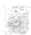
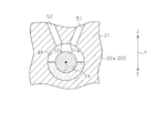
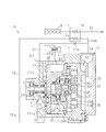
- the schematic diagram which shows the Rankine cycle apparatus in embodiment The fragmentary longitudinal cross-sectional view of the composite fluid machine of the Rankine cycle apparatus of FIG.
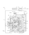
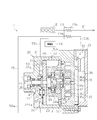
- the schematic diagram which shows the Rankine-cycle apparatus in another embodiment The schematic diagram which shows the Rankine-cycle apparatus in another embodiment.
- the schematic diagram which shows the Rankine-cycle apparatus in another embodiment The schematic diagram which shows the Rankine-cycle apparatus in another embodiment.
- the Rankine cycle apparatus 10 includes a complex fluid machine 20 including an integrated pump 11 and an expander 12.
- the Rankine cycle device 10 includes a working fluid path 15 through which the working fluid circulates.
- the working fluid path 15 includes a pump 11, a heat exchanger 13, an expander 12, and a condenser 14 that are sequentially connected.
- the composite fluid machine 20 has a housing 21 including a housing main body 22 having a covered cylindrical shape and a rear housing member 23 joined to an opening end of the housing main body 22.
- a drive shaft 24 is accommodated in the housing body 22.
- the housing body 22 has a lid portion 22a.
- a concave portion 221 a is formed on the surface of the lid portion 22 a facing the housing 21 so as to surround the drive shaft 24.
- the side plate 26 is fixed to the surface of the lid 22a facing the housing 21, whereby the recess 221a is closed, and the pump chamber 27 is defined between the lid 22a and the side plate 26.
- a driven gear 28 is rotatably accommodated in the pump chamber 27.
- a drive shaft 24 extends in the pump chamber 27.
- a main drive gear 29 attached to the drive shaft 24 is accommodated in the pump chamber 27.
- the driven gear 28 and the main driving gear 29 are accommodated in the pump chamber 27 while being engaged with each other.
- the driven gear 28 and the main driving gear 29 constitute a pump operating unit 30 that operates in accordance with the rotational drive of the drive shaft 24.
- a suction passage 31 communicating with the pump chamber 27 (recess 221a) is formed in the lid portion 22a.
- the suction passage 31 is formed in the upper part of the composite fluid machine 20 so as to open on the upper surface of the housing body 22.
- a discharge passage 32 communicating with the pump chamber 27 (recess 221a) is formed in the lid portion 22a.
- the discharge passage 32 is formed so as to be located under the pump chamber 27.
- a substantially cylindrical support block 34 constituting a part of the housing 21 is fixed in the housing main body 22.
- the support block 34 partitions the space in the housing body 22 into a space facing the rear housing member 23 and a space facing the lid portion 22a.
- the drive shaft 24 has a first end part closer to the rear housing and a second end part opposite to the first end part. The first end portion passes through the side plate 26 and is inserted into the support block 34.
- a seal member 34 s is disposed between the support block 34 and the drive shaft 24. The seal member 34 s seals between the inner peripheral surface of the support block 34 and the peripheral surface of the drive shaft 24.
- An eccentric shaft 24 a is provided on the end surface of the first end portion of the drive shaft 24 at a position eccentric with respect to the central axis L of the drive shaft 24.
- the eccentric shaft 24 a revolves around the central axis L by the rotation of the drive shaft 24.
- a bush 24b is fixed to the eccentric shaft 24a.
- the bush 24b revolves around the central axis L together with the eccentric shaft 24a.
- a counterweight 24d is fixed to the bush 24b.
- the expander 12 is fixed to the housing body 22 so as to face the movable scroll 35 between the support block 34 and the rear housing member 23, and the movable scroll 35 rotatably supported by the bush 24b via the bearing device 24c.
- a fixed scroll 36 provided.
- the movable scroll 35 includes a disk-shaped movable substrate 35a supported by the bearing device 24c, and a spiral movable spiral wall 35b protruding from the movable substrate 35a.
- the fixed scroll 36 includes a fixed substrate 36a having a disk shape and a spiral fixed spiral wall 36b projecting from the fixed substrate 36a toward the movable substrate 35a.
- the movable spiral wall 35b of the movable scroll 35 and the fixed spiral wall 36b of the fixed scroll 36 are engaged with each other to define a working chamber 37 whose volume can be changed.
- a suction port 36c is formed in the center of the fixed substrate 36a.
- a suction chamber 38 is defined between the fixed substrate 36a and the rear housing member 23, and the suction chamber 38 communicates with the working chamber 37 before the volume is expanded via the suction port 36c.
- the rear housing member 23 is formed with a suction port 39 communicating with the suction chamber 38. Further, a discharge chamber 40 is defined between the inner peripheral surface of the fixed scroll 36 and the outermost peripheral surface of the movable scroll 35. The discharge chamber 40 communicates with a discharge space 41 defined between the support block 34 and the side plate 26 in the housing body 22 through a through hole 34 h of the support block 34. A discharge port 42 communicating with the discharge space 41 is formed in the upper portion of the housing body 22.
- a back pressure chamber 45 is defined between the movable substrate 35 a of the movable scroll 35 and the inner surface of the support block 34.
- the movable scroll 35 has a facing surface that faces the fixed scroll 36 and a back surface that is opposite to the facing surface and faces the support block 34. The back surface is exposed to the back pressure chamber 45.
- a working fluid is introduced into the back pressure chamber 45.
- the pressure of the working fluid introduced into the back pressure chamber 45 is adjusted to an intermediate pressure between the pressure of the working fluid before expansion in the working chamber 37 and the pressure of the working fluid after expansion in the working chamber 37. ing.
- the movable scroll 35 is pressed against the fixed scroll 36 by the back pressure that is the pressure of the working fluid in the back pressure chamber 45.
- the housing 21 of the composite fluid machine 20 serves as both the housing of the pump 11 and the housing of the expander 12.
- the drive shaft 24 serves as both the pump shaft of the pump 11 and the drive shaft of the expander 12.
- annular shaft seal member 47 that seals between the lid portion 22 a of the housing body 22 and the drive shaft 24 is accommodated.
- the shaft seal member 47 prevents the working fluid in the composite fluid machine 20 from leaking to the atmosphere by sealing between the lid portion 22a of the housing body 22 and the drive shaft 24.
- a shaft seal chamber 46 is defined by the shaft seal member 47, the drive shaft 24, the lid portion 22 a of the housing body 22, and the pump operating unit 30.
- the shaft seal chamber 46 is formed in an annular shape so as to surround the drive shaft 24.
- An annular seal member 48 that seals between the pump chamber 27 and the shaft seal chamber 46 is accommodated in the shaft seal chamber 46.
- the second end portion of the drive shaft 24 is rotatably supported by the lid portion 22a via the rolling bearing 25, and the first end portion of the drive shaft 24 is provided with a rolling bearing 34a provided in the support block 34.
- the rolling bearing 25 is disposed between the shaft seal chamber 46 and the end surface of the second end portion of the drive shaft 24. That is, the rolling bearing 25 is disposed outside the shaft seal chamber 46.
- the heat exchanger 13 includes a heat absorber 13a and a heat radiator 13b.
- the outlet of the pump chamber 27 is connected to the heat absorber 13a (the inlet of the heat exchanger 13) via the discharge passage 32 and the first flow path 50a.
- the radiator 13b is provided on the exhaust pipe E1 connected to the vehicle engine E as an exhaust heat source. And the exhaust gas discharged
- the outlet of the heat absorber 13a of the heat exchanger 13 (the outlet of the heat exchanger 13) is connected to the suction port 39 (the inlet of the expander 12) via the second flow path 50b.
- the high-temperature and high-pressure working fluid heated and vaporized by the heat exchanger 13 is sucked into the working chamber 37 through the second flow path 50b, the suction port 39, the suction chamber 38, and the suction port 36c.
- the working fluid sucked into the working chamber 37 expands in the working chamber 37, and a part of the heat quantity of the working fluid is taken out as mechanical energy, and power generation by a generator (not shown), torque assistance of the vehicle engine E, etc. Done.
- the discharge port 42 (exit of the expander 12) is connected to the inlet of the condenser 14 via the third flow path 50c.
- the high-temperature and low-pressure working fluid expanded by the expander 12 is discharged to the condenser 14 via the third flow path 50c.
- the working fluid discharged to the condenser 14 is condensed and liquefied by heat exchange with the outside air.
- the outlet of the condenser 14 is connected to the inlet of the pump chamber 27 via the fourth flow path 50d and the suction passage 31. Then, the low-temperature and low-pressure working fluid condensed and liquefied by the condenser 14 is sucked into the pump chamber 27 via the fourth flow path 50d and the suction passage 31, and the working fluid path is formed by the operation of the pump operating section 30. Circulate 15. Therefore, in the Rankine cycle device 10, the working fluid flows through the circuit along the order of the expander 12, the condenser 14, the pump 11 of the composite fluid machine 20, and the heat exchanger 13 of the composite fluid machine 20. .
- the back pressure chamber 45 and the shaft seal chamber 46 communicate with each other via the first communication passage 51. Therefore, the first communication path 51 is connected to a connection point located between the outlet of the heat exchanger 13 and the inlet of the condenser 14 in the working fluid path 15, that is, the first connection part.
- the first communication passage 51 is provided with a first throttle portion 51s.
- the working fluid in the back pressure chamber 45 is supplied to the shaft seal chamber 46 via the first communication passage 51 in a state where the working fluid is throttled and depressurized by the first throttle portion 51s.
- the shaft seal chamber 46 and the discharge space 41 communicate with each other via the second communication passage 52.
- the pressure in the discharge space 41 is lower than the pressure in the back pressure chamber 45. Therefore, the 2nd communicating path 52 is connected to the location where the pressure is lower than the pressure of the said 1st connection location, ie, the 2nd connection location.
- the opening 51 a with respect to the shaft seal chamber 46 in the first communication passage 51 is disposed above the center axis L of the drive shaft 24 in the gravity direction (the direction of the arrow Y shown in FIG. 2).
- the opening 52 a with respect to the shaft seal chamber 46 in the second communication passage 52 is disposed above the center axis L of the drive shaft 24 in the gravity direction.
- Lubricating oil together with the vaporized working fluid in the back pressure chamber 45 is supplied to the shaft seal chamber 46 via the first communication passage 51. Therefore, the shaft seal chamber 46 is filled with the vaporized working fluid mixed with the lubricating oil. Further, since the second communication passage 52 is connected to a location where the pressure is lower than the pressure at the connection location of the first communication passage 51 with respect to the working fluid passage 15, the second communication passage 52 is connected to the shaft seal chamber 46 via the first communication passage 51. The supplied working fluid returns to the working fluid path 15 through the second communication path 52.
- the working fluid supplied to the shaft seal chamber 46 via the first communication path 51 is condensed and liquefied by being cooled by the working fluid sent from the condenser 14 to the pump chamber 27, and liquefied.
- the working fluid is prevented from accumulating in the shaft seal chamber 46.
- the viscosity of the lubricating oil supplied to the shaft seal chamber 46 is maintained at a high level, and the lubricating performance between the shaft seal member 47 and the drive shaft 24 is improved.
- the opening 51a with respect to the shaft seal chamber 46 in the first communication passage 51 is disposed above the central axis L of the drive shaft 24 in the gravity direction, the lubricating oil stored in the shaft seal chamber 46 is Stirring by the working fluid supplied to the shaft seal chamber 46 through the opening 51a with respect to the shaft seal chamber 46 in the one communication path 51 is suppressed.
- the opening 52a for the shaft seal chamber 46 in the second communication passage 52 is disposed above the central axis L of the drive shaft 24 in the gravity direction, the opening 52a for the shaft seal chamber 46 in the second communication passage 52 is provided. Compared to the case where the drive shaft 24 is arranged below the center axis L of the drive shaft 24 in the direction of gravity, the lubricating oil is easily stored in the shaft seal chamber 46.
- the pressure in the shaft seal chamber 46 is lower than the pressure in the back pressure chamber 45. Therefore, compared with the case where the pressure in the shaft seal chamber 46 is the same as the pressure in the back pressure chamber 45, the load applied to the shaft seal member 47 is reduced, and the durability of the shaft seal member 47 is improved. .
- the rolling bearing 25 Since the rolling bearing 25 is disposed outside the shaft seal chamber 46, the rolling bearing 25 is stored in the shaft seal chamber 46 by the rolling bearing 25 as in the case where the rolling bearing 25 is disposed in the shaft seal chamber 46, for example.
- the problem that the shaft seal member 47 deteriorates due to the heat of the lubricant that has been stirred and the temperature of the lubricant that has been stirred up has been avoided.
- the back pressure chamber 45 and the shaft seal chamber 46 communicate with each other via the first communication passage 51. Further, the shaft seal chamber 46 and the discharge space 41 communicate with each other via the second communication passage 52.
- the second communication passage 52 is connected to a location where the pressure is lower than the pressure at the location where the first communication passage 51 is connected to the working fluid passage 15. According to this, the lubricating oil together with the vaporized working fluid in the back pressure chamber 45 through the first communication passage 51 is located between the outlet of the heat exchanger 13 and the inlet of the condenser 14, that is, the shaft seal chamber 46. Therefore, the shaft seal chamber 46 can be filled with the vaporized working fluid mixed with the lubricating oil.
- the second communication passage 52 is connected to a location where the pressure is lower than the pressure at the connection location of the first communication passage 51 with respect to the working fluid passage 15, the second communication passage 52 is connected to the shaft seal chamber 46 via the first communication passage 51.
- the supplied working fluid can be recirculated to the working fluid path 15 via the second communication path 52. Therefore, the working fluid supplied to the shaft seal chamber 46 via the first communication path 51 is condensed and liquefied by being cooled by the working fluid sent from the condenser 14 to the pump chamber 27, and liquefied. It is possible to prevent the working fluid from accumulating in the shaft seal chamber 46. As a result, the viscosity of the lubricating oil supplied to the shaft seal chamber 46 can be maintained at a high level, and the lubricating performance between the shaft seal member 47 and the drive shaft 24 can be improved.
- the first throttle part 51 s is provided in the first communication path 51. According to this, the pressure in the shaft seal chamber 46 can be made lower than the pressure in the back pressure chamber 45. Therefore, compared with the case where the pressure in the shaft seal chamber 46 is the same as the pressure in the back pressure chamber 45, the load applied to the shaft seal member 47 can be reduced, and the durability of the shaft seal member 47 can be reduced. Can be improved.
- the first communication path 51 was connected to the back pressure chamber 45. According to this, the working fluid supplied to the back pressure chamber 45 can contribute to the lubrication between the shaft seal member 47 and the drive shaft 24, and the working fluid supplied to the back pressure chamber 45 is effectively used. can do.
- the Rankine cycle apparatus 10 includes a composite fluid machine 20 in which a pump 11 and an expander 12 are integrated. Such a configuration is suitable as a configuration for supplying the working fluid from the back pressure chamber 45 to the shaft seal chamber 46 via the first communication passage 51.
- the opening 52 a with respect to the shaft seal chamber 46 in the second communication passage 52 is disposed above the central axis L of the drive shaft 24 in the gravity direction. According to this, compared with the case where the opening 52a with respect to the shaft seal chamber 46 in the second communication path 52 is disposed below the central axis L of the drive shaft 24 in the gravity direction, the shaft seal chamber 46 has a larger opening. Lubricating oil can be easily stored.
- the opening 51 a with respect to the shaft seal chamber 46 in the first communication passage 51 is disposed above the central axis L of the drive shaft 24 in the gravity direction. According to this, the lubricating oil stored in the shaft seal chamber 46 is agitated by the working fluid supplied to the shaft seal chamber 46 via the opening 51 a for the shaft seal chamber 46 in the first communication passage 51. Therefore, the lubricating oil can be easily stored in the shaft seal chamber 46.
- a seal member 48 for sealing between the pump chamber 27 and the shaft seal chamber 46 is provided between the housing body 22 and the drive shaft 24. According to this, it is possible to prevent the working fluid sent from the condenser 14 to the pump chamber 27 from flowing into the shaft seal chamber 46 via the space between the housing body 22 and the drive shaft 24.
- the rolling bearing 25 is disposed outside the shaft seal chamber 46. According to this, the lubricating oil stored in the shaft seal chamber 46 is agitated and agitated by the rolling bearing 25 as in the case where the rolling bearing 25 is disposed in the shaft seal chamber 46, for example. Thus, the problem that the shaft seal member 47 deteriorates due to the heat of the lubricating oil whose temperature has increased can be avoided.
- the second communication passage 52 may be connected to the suction passage 31.
- the second communication passage 52 is provided with a second throttle portion 52s.
- the flow path area of the second throttle part 52s is larger than the flow path area of the first throttle part 51s. According to this, the 2nd communicating path 52 can be shortened as much as possible.
- the second throttle passage 52 s is provided in the second communication passage 52, thereby preventing the working fluid flowing through the suction passage 31 from flowing into the shaft seal chamber 46 through the second communication passage 52. be able to.
- the second communication path 52 may be connected to the fourth flow path 50 d, that is, connected to a location between the outlet of the condenser 14 and the inlet of the pump chamber 27.
- the pressure in the shaft seal chamber 46 can be reduced as compared with the case where the flow path area of the second throttle part 52s is smaller than the flow path area of the first throttle part 51s. Therefore, the load applied to the shaft seal member 47 can be further reduced, and the durability of the shaft seal member 47 can be further improved.
- the first communication path 51 may pass through the inside of the drive shaft 24. According to this, it is not necessary to separately provide an arrangement space for the first communication path 51, and the configuration can be simplified.
- the first communication path 51 may be connected to the second flow path 50b.
- the second communication passage 52 may pass through the inside of the drive shaft 24 and be connected to the back pressure chamber 45.
- the first communication path 51 may be connected to a location between the outlet of the heat exchanger 13 and the inlet of the condenser 14.
- the 2nd communicating path 52 should just be connected to the location where the pressure is lower than the pressure of the connection location of the 1st communicating path 51 with respect to the working fluid path 15.
- FIG. According to the embodiment shown in FIG. 5, the working fluid in the shaft seal chamber 46 is returned to the back pressure chamber 45 via the second communication passage 52, so that the pressure of the working fluid in the shaft seal chamber 46 is changed to the movable scroll 35. Can be used as the back pressure required to press the pressure on the fixed scroll 36. Further, there is no need to provide a separate space for the second communication passage 52, and the configuration can be simplified.
- the rolling bearing 25 may be disposed between the pump chamber 27 and the shaft seal chamber 46 in the axial direction of the drive shaft 24.
- the rolling bearing 25 may be disposed in the shaft seal chamber 46.
- a sliding bearing may be used instead of the rolling bearing 25, a sliding bearing may be used.
- the opening 51 a with respect to the shaft seal chamber 46 in the first communication path 51 may be disposed below the center axis L of the drive shaft 24 in the gravity direction.
- An opening 52 a for the shaft seal chamber 46 in the second communication passage 52 may be disposed below the center axis L of the drive shaft 24 in the gravity direction.
- the pump 11 and the expander 12 may be separate.
- the pump shaft of the pump 11 and the drive shaft of the expander 12 may be used as a single drive shaft, or the pump shaft of the pump 11 and the drive shaft of the expander 12 are provided individually. May be.
- the shaft seal member 47, the drive shaft 24, the lid portion 22a of the housing main body 22, and the pump operating unit 30 may be provided with a heat insulating coating on the respective portions that define the shaft seal chamber 46. According to this, it is possible to prevent the working fluid supplied to the shaft seal chamber 46 via the first communication path 51 from being cooled by the working fluid sent from the condenser 14 to the pump chamber 27.
- an opening adjustment valve 61s that can adjust the opening of the first communication passage 51 may be provided as the first throttle portion.
- the pump 11 and the expander 12 are separate bodies.
- the pump 11 has a housing 21A including a housing body 22A and a side plate 26A.
- the second end portion of the drive shaft 24 is rotatably supported by the housing body 22A via the rolling bearing 25, and the first end portion of the drive shaft 24 is provided with a rolling bearing 34A provided in the side plate 26A.
- a suction passage 31 and a discharge passage 32 communicating with the pump chamber 27 (recess 221a) are formed.
- a temperature detector 62 for detecting the temperature in the shaft seal chamber 46 is provided.
- the temperature detection unit 62 is connected to the control unit 60 so that signals can be transmitted to the control unit 60. Information on the temperature detected by the temperature detection unit 62 is sent to the control unit 60.
- a pressure detector 63 pressure sensor for detecting the pressure in the shaft seal chamber 46 is provided.
- the pressure detection unit 63 is connected to the control unit 60 so that signals can be transmitted to the control unit 60. Information on the pressure detected by the pressure detection unit 63 is sent to the control unit 60.
- the opening adjustment valve 61s is built in the housing body 22A and is electrically connected to the control unit 60.
- the controller 60 controls the valve opening of the opening adjustment valve 61s based on the temperature detected by the temperature detector 62 and the pressure detected by the pressure detector 63.
- the controller 60 stores in advance a map for obtaining the saturation temperature of the working fluid supplied to the shaft seal chamber 46 based on the pressure detected by the pressure detector 63.
- the pressure in the shaft seal chamber 46 is equal to the pressure of the working fluid supplied to the shaft seal chamber 46. Since the pressure of the working fluid has a correlation with the saturation temperature of the working fluid, the control unit 60 obtains the saturation temperature of the working fluid in advance from a map stored in advance based on the pressure detected by the pressure detection unit 63.
- the temperature in the shaft seal chamber 46 is equal to the temperature of the working fluid supplied to the shaft seal chamber 46.
- the control part 60 calculates the superheat degree of the working fluid which deducted the saturation temperature of the working fluid from the temperature of the working fluid.
- the control part 60 controls the opening degree of the opening degree adjustment valve 61s so that the valve opening degree of the opening degree adjustment valve 61s increases when the calculated degree of superheat is equal to or less than a predetermined value.
- the flow rate of the working fluid supplied to the shaft seal chamber 46 via the first communication passage 51 increases, the temperature in the shaft seal chamber 46 rises, and the working fluid in the shaft seal chamber 46 increases. It can suppress that it cools and condenses and liquefies. As a result, the viscosity of the lubricating oil supplied to the shaft seal chamber 46 can be easily maintained at a high level, and the lubricating performance between the shaft seal member 47 and the drive shaft 24 can be further improved. it can.
- the control unit 60 controls the opening of the opening adjustment valve 61s so that the opening of the opening adjustment valve 61s decreases. According to this, since the flow rate of the working fluid supplied to the shaft seal chamber 46 via the first communication passage 51 decreases, it is possible to suppress the temperature in the shaft seal chamber 46 from excessively rising. . As a result, it is possible to avoid the problem that the shaft seal member 47 is deteriorated by the heat of the lubricating oil whose temperature has increased.
- the control unit 60 controls the valve opening of the opening adjustment valve 61 s based on the temperature detected by the temperature detection unit 62 and the pressure detected by the pressure detection unit 63. Yes.
- the shaft seal chamber 46 is supplied via the first communication passage 51. It is possible to control the flow rate of the working fluid to be accurately performed, and to further prevent the working fluid in the shaft seal chamber 46 from being cooled, condensed and liquefied.
- the opening adjustment valve 61s is built in the housing main body 22A. According to this, the opening degree adjusting valve 61 s can be cooled by the working fluid sent from the condenser 14 to the pump chamber 27. Therefore, it can suppress that the opening degree adjustment valve 61s deteriorates with the heat
- the pressure detector 63 may be deleted.
- the control unit 60 sets the opening adjustment valve 61s so that the opening degree of the opening adjustment valve 61s increases.
- the opening degree may be controlled. Even in this case, since the flow rate of the working fluid supplied to the shaft seal chamber 46 via the first communication passage 51 increases, the temperature in the shaft seal chamber 46 rises and the operation in the shaft seal chamber 46 increases. It is possible to prevent the fluid from being cooled and condensed and liquefied.
- the opening adjustment valve 61 s may not be built in the housing body 22 ⁇ / b> A and may be disposed in the first communication path 51 independently of the housing 21 ⁇ / b> A of the pump 11.
- the embodiment shown in FIG. 7 includes an opening adjustment valve 70 that is autonomously controlled.
- the opening adjustment valve 70 has a valve housing 71 through which the first communication path 51 and the second communication path 52 pass.
- a valve hole 71 h that constitutes a part of the first communication path 51 is formed in the middle of the first communication path 51 in the valve housing 71.
- a valve body 72 that adjusts the opening degree of the first communication path 51 is disposed in the first communication path 51.
- a biasing spring 73 that biases the valve body 72 toward the valve hole 71h is disposed in the first communication passage 51.
- the valve housing 71 is provided with a housing member 76 that defines a housing chamber 75 that houses a diaphragm 74 as a pressure-sensitive member.
- the storage chamber 75 is partitioned into a first pressure chamber 77 and a second pressure chamber 78 by a diaphragm 74.
- the first pressure chamber 77 is filled with a working fluid in a gas-liquid mixed state (saturated state).
- a rod-shaped heat transfer member 79 is provided across the second communication path 52.
- One end of the heat transfer member 79 is joined to the valve body 72, and the other end is located in the second pressure chamber 78 and joined to the diaphragm 74.
- the heat transfer member 79 moves as the diaphragm 74 is displaced.
- the heat transfer member 79 transmits the heat of the working fluid flowing through the second communication passage 52 from the shaft seal chamber 46 to the first pressure chamber 77. Since the working fluid flowing through the second communication passage 52 is the working fluid flowing out from the shaft seal chamber 46, the heat of the working fluid flowing through the second communication passage 52 is equal to the heat in the shaft seal chamber 46. That is, the heat transfer member 79 transmits the heat in the shaft seal chamber 46 to the first pressure chamber 77. The heat in the shaft seal chamber 46 transmitted through the heat transfer member 79 is transmitted to the working fluid in the first pressure chamber 77, whereby the temperature of the working fluid in the first pressure chamber 77 changes. The pressure in the first pressure chamber 77 becomes a saturation pressure corresponding to the temperature. That is, the pressure in the first pressure chamber 77 is determined based on the temperature in the shaft seal chamber 46.
- the second pressure chamber 78 communicates with the second communication passage 52 through a gap between the heat transfer member 79 and the valve housing 71. Therefore, the second pressure chamber 78 communicates with the shaft seal chamber 46 via the second communication passage 52, and the pressure of the shaft seal chamber 46 is introduced into the second pressure chamber 78.
- the opening degree of the valve hole 71h increases, the flow rate of the working fluid supplied to the shaft seal chamber 46 via the first communication passage 51 increases. Therefore, it is possible to prevent the temperature in the shaft seal chamber 46 from rising and the working fluid in the shaft seal chamber 46 from being cooled and condensed to be liquefied. As a result, the viscosity of the lubricating oil supplied to the shaft seal chamber 46 can be easily maintained at a high level, and the lubricating performance between the shaft seal member 47 and the drive shaft 24 can be further improved. it can. According to the opening degree adjusting valve 70 shown in FIG. 7, since it is not necessary to electrically control the opening degree adjusting valve 70, the control of the opening degree of the first communication path 51 can be simplified.
- a bellows may be used as the pressure sensitive member.
- the heat transfer member 79 and the valve body 72 may not be joined, and the heat transfer member 79 and the valve body 72 may be separate.
- the first throttle 51s may be deleted and a throttle may be provided in the second communication path 52.
- the pump operating unit 30 may not be configured by the driven gear 28 and the main driving gear 29, and may be another form of the pump operating unit 30.
Landscapes
- Engineering & Computer Science (AREA)
- Mechanical Engineering (AREA)
- General Engineering & Computer Science (AREA)
- Chemical & Material Sciences (AREA)
- Combustion & Propulsion (AREA)
- Applications Or Details Of Rotary Compressors (AREA)
- Engine Equipment That Uses Special Cycles (AREA)
Abstract
L'invention concerne un dispositif à cycle de Rankine (10) équipé de : un logement (21) possédant une chambre d'aspiration (27) ; une pompe (11) possédant un arbre de pompe et une unité d'exploitation de pompe (30), l'unité d'exploitation de pompe étant actionnée par la rotation de l'arbre de pompe ; un conduit de fluide de travail (15) qui comprend la pompe, un échangeur thermique (13), un dispositif d'expansion (12), et un condenseur (14), et dans lequel circule le fluide de travail ; un élément de joint d'arbre (47) qui scelle un espace entre le logement et l'arbre de pompe, à l'intérieur du logement ; une chambre de scellage de pompe (46) définie par l'élément de joint d'arbre, l'arbre de pompe, le logement, et l'unité d'exploitation de pompe ; un premier conduit de raccordement (51), qui est relié à un premier site de raccordement situé entre une sortie de l'échangeur thermique et une entrée du condenseur dans le conduit de fluide de travail, et qui communique avec la chambre de scellage d'arbre ; et un second conduit de raccordement (52), qui communique avec la chambre de scellage d'arbre et est relié à un second site de raccordement dans le conduit de fluide de travail, la pression au sein du second site de raccordement étant inférieure à la pression au sein du premier site de raccordement.
Applications Claiming Priority (4)
| Application Number | Priority Date | Filing Date | Title |
|---|---|---|---|
| JP2013-131818 | 2013-06-24 | ||
| JP2013131818 | 2013-06-24 | ||
| JP2013-252257 | 2013-12-05 | ||
| JP2013252257A JP2015028334A (ja) | 2013-06-24 | 2013-12-05 | ランキンサイクル装置 |
Publications (1)
| Publication Number | Publication Date |
|---|---|
| WO2014208252A1 true WO2014208252A1 (fr) | 2014-12-31 |
Family
ID=52141604
Family Applications (1)
| Application Number | Title | Priority Date | Filing Date |
|---|---|---|---|
| PCT/JP2014/064003 Ceased WO2014208252A1 (fr) | 2013-06-24 | 2014-05-27 | Dispositif à cycle de rankine |
Country Status (2)
| Country | Link |
|---|---|
| JP (1) | JP2015028334A (fr) |
| WO (1) | WO2014208252A1 (fr) |
Citations (2)
| Publication number | Priority date | Publication date | Assignee | Title |
|---|---|---|---|---|
| JP2008075637A (ja) * | 2006-09-25 | 2008-04-03 | Nippon Soken Inc | 流体機械 |
| WO2012020630A1 (fr) * | 2010-08-09 | 2012-02-16 | 株式会社 豊田自動織機 | Appareil d'utilisation d'une déperdition de chaleur |
-
2013
- 2013-12-05 JP JP2013252257A patent/JP2015028334A/ja active Pending
-
2014
- 2014-05-27 WO PCT/JP2014/064003 patent/WO2014208252A1/fr not_active Ceased
Patent Citations (2)
| Publication number | Priority date | Publication date | Assignee | Title |
|---|---|---|---|---|
| JP2008075637A (ja) * | 2006-09-25 | 2008-04-03 | Nippon Soken Inc | 流体機械 |
| WO2012020630A1 (fr) * | 2010-08-09 | 2012-02-16 | 株式会社 豊田自動織機 | Appareil d'utilisation d'une déperdition de chaleur |
Also Published As
| Publication number | Publication date |
|---|---|
| JP2015028334A (ja) | 2015-02-12 |
Similar Documents
| Publication | Publication Date | Title |
|---|---|---|
| US8186179B2 (en) | Expander-compressor unit | |
| JP5695187B2 (ja) | 冷媒圧縮機及びこれを用いた冷凍サイクル装置 | |
| JP6302813B2 (ja) | スクロール圧縮機及びこれを用いた冷凍サイクル装置 | |
| US8398387B2 (en) | Fluid machine and refrigeration cycle apparatus | |
| JP4969648B2 (ja) | 膨張機一体型圧縮機およびそれを備えた冷凍サイクル装置 | |
| WO2009141956A1 (fr) | Machine à fluide et dispositif à cycle de réfrigération | |
| JP2012207655A (ja) | ランキンサイクル装置 | |
| JPWO2008139667A1 (ja) | 冷凍サイクル装置及びそれに用いる流体機械 | |
| JP5969226B2 (ja) | 流体機械 | |
| JP5969227B2 (ja) | 流体機械 | |
| JP2001055988A (ja) | スクロール圧縮機 | |
| WO2013140458A1 (fr) | Compresseur à volute | |
| JP2015028334A (ja) | ランキンサイクル装置 | |
| US20100014999A1 (en) | Scroll-type expansion machine | |
| JP2002242858A (ja) | スクロール圧縮機 | |
| JP2006220143A (ja) | 容積形流体機械及びそれを用いた冷凍サイクル | |
| JP2015031210A (ja) | ランキンサイクル装置 | |
| JP2014001667A (ja) | ランキンサイクル装置 | |
| JP2007263097A (ja) | 容量可変型圧縮機における流量検出装置 | |
| JP2019039620A (ja) | 冷凍サイクル装置 | |
| JP4657910B2 (ja) | スクロール形膨張機及びランキンサイクル発電システム | |
| JP2008075637A (ja) | 流体機械 | |
| JP2010038120A (ja) | 流体機械 | |
| JP2015007372A (ja) | ランキンサイクル装置 | |
| JP2008291779A (ja) | 密閉形スクロール圧縮機及び冷凍空調装置 |
Legal Events
| Date | Code | Title | Description |
|---|---|---|---|
| 121 | Ep: the epo has been informed by wipo that ep was designated in this application |
Ref document number: 14818400 Country of ref document: EP Kind code of ref document: A1 |
|
| NENP | Non-entry into the national phase |
Ref country code: DE |
|
| 122 | Ep: pct application non-entry in european phase |
Ref document number: 14818400 Country of ref document: EP Kind code of ref document: A1 |