WO2014208332A1 - Unité spiralée, dispositif d'insertion, et procédé de fabrication d'unité spiralée - Google Patents
Unité spiralée, dispositif d'insertion, et procédé de fabrication d'unité spiralée Download PDFInfo
- Publication number
- WO2014208332A1 WO2014208332A1 PCT/JP2014/065376 JP2014065376W WO2014208332A1 WO 2014208332 A1 WO2014208332 A1 WO 2014208332A1 JP 2014065376 W JP2014065376 W JP 2014065376W WO 2014208332 A1 WO2014208332 A1 WO 2014208332A1
- Authority
- WO
- WIPO (PCT)
- Prior art keywords
- fin
- base tube
- resin
- spiral unit
- longitudinal axis
- Prior art date
- Legal status (The legal status is an assumption and is not a legal conclusion. Google has not performed a legal analysis and makes no representation as to the accuracy of the status listed.)
- Ceased
Links
Images





Classifications
-
- A—HUMAN NECESSITIES
- A61—MEDICAL OR VETERINARY SCIENCE; HYGIENE
- A61B—DIAGNOSIS; SURGERY; IDENTIFICATION
- A61B1/00—Instruments for performing medical examinations of the interior of cavities or tubes of the body by visual or photographical inspection, e.g. endoscopes; Illuminating arrangements therefor
- A61B1/00064—Constructional details of the endoscope body
- A61B1/0011—Manufacturing of endoscope parts
-
- A—HUMAN NECESSITIES
- A61—MEDICAL OR VETERINARY SCIENCE; HYGIENE
- A61B—DIAGNOSIS; SURGERY; IDENTIFICATION
- A61B1/00—Instruments for performing medical examinations of the interior of cavities or tubes of the body by visual or photographical inspection, e.g. endoscopes; Illuminating arrangements therefor
- A61B1/00131—Accessories for endoscopes
- A61B1/00135—Oversleeves mounted on the endoscope prior to insertion
-
- A—HUMAN NECESSITIES
- A61—MEDICAL OR VETERINARY SCIENCE; HYGIENE
- A61B—DIAGNOSIS; SURGERY; IDENTIFICATION
- A61B1/00—Instruments for performing medical examinations of the interior of cavities or tubes of the body by visual or photographical inspection, e.g. endoscopes; Illuminating arrangements therefor
- A61B1/00147—Holding or positioning arrangements
- A61B1/00148—Holding or positioning arrangements using anchoring means
-
- A—HUMAN NECESSITIES
- A61—MEDICAL OR VETERINARY SCIENCE; HYGIENE
- A61B—DIAGNOSIS; SURGERY; IDENTIFICATION
- A61B1/00—Instruments for performing medical examinations of the interior of cavities or tubes of the body by visual or photographical inspection, e.g. endoscopes; Illuminating arrangements therefor
- A61B1/00147—Holding or positioning arrangements
- A61B1/00154—Holding or positioning arrangements using guiding arrangements for insertion
-
- A—HUMAN NECESSITIES
- A61—MEDICAL OR VETERINARY SCIENCE; HYGIENE
- A61B—DIAGNOSIS; SURGERY; IDENTIFICATION
- A61B1/00—Instruments for performing medical examinations of the interior of cavities or tubes of the body by visual or photographical inspection, e.g. endoscopes; Illuminating arrangements therefor
- A61B1/00147—Holding or positioning arrangements
- A61B1/0016—Holding or positioning arrangements using motor drive units
-
- A—HUMAN NECESSITIES
- A61—MEDICAL OR VETERINARY SCIENCE; HYGIENE
- A61B—DIAGNOSIS; SURGERY; IDENTIFICATION
- A61B17/00—Surgical instruments, devices or methods
-
- A—HUMAN NECESSITIES
- A61—MEDICAL OR VETERINARY SCIENCE; HYGIENE
- A61B—DIAGNOSIS; SURGERY; IDENTIFICATION
- A61B34/00—Computer-aided surgery; Manipulators or robots specially adapted for use in surgery
-
- A—HUMAN NECESSITIES
- A61—MEDICAL OR VETERINARY SCIENCE; HYGIENE
- A61M—DEVICES FOR INTRODUCING MEDIA INTO, OR ONTO, THE BODY; DEVICES FOR TRANSDUCING BODY MEDIA OR FOR TAKING MEDIA FROM THE BODY; DEVICES FOR PRODUCING OR ENDING SLEEP OR STUPOR
- A61M25/00—Catheters; Hollow probes
- A61M25/01—Introducing, guiding, advancing, emplacing or holding catheters
-
- B—PERFORMING OPERATIONS; TRANSPORTING
- B29—WORKING OF PLASTICS; WORKING OF SUBSTANCES IN A PLASTIC STATE IN GENERAL
- B29C—SHAPING OR JOINING OF PLASTICS; SHAPING OF MATERIAL IN A PLASTIC STATE, NOT OTHERWISE PROVIDED FOR; AFTER-TREATMENT OF THE SHAPED PRODUCTS, e.g. REPAIRING
- B29C65/00—Joining or sealing of preformed parts, e.g. welding of plastics materials; Apparatus therefor
- B29C65/02—Joining or sealing of preformed parts, e.g. welding of plastics materials; Apparatus therefor by heating, with or without pressure
- B29C65/14—Joining or sealing of preformed parts, e.g. welding of plastics materials; Apparatus therefor by heating, with or without pressure using wave energy, i.e. electromagnetic radiation, or particle radiation
- B29C65/1403—Joining or sealing of preformed parts, e.g. welding of plastics materials; Apparatus therefor by heating, with or without pressure using wave energy, i.e. electromagnetic radiation, or particle radiation characterised by the type of electromagnetic or particle radiation
-
- B—PERFORMING OPERATIONS; TRANSPORTING
- B29—WORKING OF PLASTICS; WORKING OF SUBSTANCES IN A PLASTIC STATE IN GENERAL
- B29C—SHAPING OR JOINING OF PLASTICS; SHAPING OF MATERIAL IN A PLASTIC STATE, NOT OTHERWISE PROVIDED FOR; AFTER-TREATMENT OF THE SHAPED PRODUCTS, e.g. REPAIRING
- B29C65/00—Joining or sealing of preformed parts, e.g. welding of plastics materials; Apparatus therefor
- B29C65/02—Joining or sealing of preformed parts, e.g. welding of plastics materials; Apparatus therefor by heating, with or without pressure
- B29C65/34—Joining or sealing of preformed parts, e.g. welding of plastics materials; Apparatus therefor by heating, with or without pressure using heated elements which remain in the joint, e.g. "verlorenes Schweisselement"
- B29C65/36—Joining or sealing of preformed parts, e.g. welding of plastics materials; Apparatus therefor by heating, with or without pressure using heated elements which remain in the joint, e.g. "verlorenes Schweisselement" heated by induction
- B29C65/3604—Joining or sealing of preformed parts, e.g. welding of plastics materials; Apparatus therefor by heating, with or without pressure using heated elements which remain in the joint, e.g. "verlorenes Schweisselement" heated by induction characterised by the type of elements heated by induction which remain in the joint
- B29C65/3608—Joining or sealing of preformed parts, e.g. welding of plastics materials; Apparatus therefor by heating, with or without pressure using heated elements which remain in the joint, e.g. "verlorenes Schweisselement" heated by induction characterised by the type of elements heated by induction which remain in the joint comprising single particles, e.g. fillers or discontinuous fibre-reinforcements
-
- B—PERFORMING OPERATIONS; TRANSPORTING
- B29—WORKING OF PLASTICS; WORKING OF SUBSTANCES IN A PLASTIC STATE IN GENERAL
- B29C—SHAPING OR JOINING OF PLASTICS; SHAPING OF MATERIAL IN A PLASTIC STATE, NOT OTHERWISE PROVIDED FOR; AFTER-TREATMENT OF THE SHAPED PRODUCTS, e.g. REPAIRING
- B29C65/00—Joining or sealing of preformed parts, e.g. welding of plastics materials; Apparatus therefor
- B29C65/02—Joining or sealing of preformed parts, e.g. welding of plastics materials; Apparatus therefor by heating, with or without pressure
- B29C65/34—Joining or sealing of preformed parts, e.g. welding of plastics materials; Apparatus therefor by heating, with or without pressure using heated elements which remain in the joint, e.g. "verlorenes Schweisselement"
- B29C65/36—Joining or sealing of preformed parts, e.g. welding of plastics materials; Apparatus therefor by heating, with or without pressure using heated elements which remain in the joint, e.g. "verlorenes Schweisselement" heated by induction
- B29C65/3672—Joining or sealing of preformed parts, e.g. welding of plastics materials; Apparatus therefor by heating, with or without pressure using heated elements which remain in the joint, e.g. "verlorenes Schweisselement" heated by induction characterised by the composition of the elements heated by induction which remain in the joint
- B29C65/3676—Joining or sealing of preformed parts, e.g. welding of plastics materials; Apparatus therefor by heating, with or without pressure using heated elements which remain in the joint, e.g. "verlorenes Schweisselement" heated by induction characterised by the composition of the elements heated by induction which remain in the joint being metallic
-
- B—PERFORMING OPERATIONS; TRANSPORTING
- B29—WORKING OF PLASTICS; WORKING OF SUBSTANCES IN A PLASTIC STATE IN GENERAL
- B29C—SHAPING OR JOINING OF PLASTICS; SHAPING OF MATERIAL IN A PLASTIC STATE, NOT OTHERWISE PROVIDED FOR; AFTER-TREATMENT OF THE SHAPED PRODUCTS, e.g. REPAIRING
- B29C65/00—Joining or sealing of preformed parts, e.g. welding of plastics materials; Apparatus therefor
- B29C65/02—Joining or sealing of preformed parts, e.g. welding of plastics materials; Apparatus therefor by heating, with or without pressure
- B29C65/34—Joining or sealing of preformed parts, e.g. welding of plastics materials; Apparatus therefor by heating, with or without pressure using heated elements which remain in the joint, e.g. "verlorenes Schweisselement"
- B29C65/36—Joining or sealing of preformed parts, e.g. welding of plastics materials; Apparatus therefor by heating, with or without pressure using heated elements which remain in the joint, e.g. "verlorenes Schweisselement" heated by induction
- B29C65/3672—Joining or sealing of preformed parts, e.g. welding of plastics materials; Apparatus therefor by heating, with or without pressure using heated elements which remain in the joint, e.g. "verlorenes Schweisselement" heated by induction characterised by the composition of the elements heated by induction which remain in the joint
- B29C65/3684—Joining or sealing of preformed parts, e.g. welding of plastics materials; Apparatus therefor by heating, with or without pressure using heated elements which remain in the joint, e.g. "verlorenes Schweisselement" heated by induction characterised by the composition of the elements heated by induction which remain in the joint being non-metallic
-
- B—PERFORMING OPERATIONS; TRANSPORTING
- B29—WORKING OF PLASTICS; WORKING OF SUBSTANCES IN A PLASTIC STATE IN GENERAL
- B29C—SHAPING OR JOINING OF PLASTICS; SHAPING OF MATERIAL IN A PLASTIC STATE, NOT OTHERWISE PROVIDED FOR; AFTER-TREATMENT OF THE SHAPED PRODUCTS, e.g. REPAIRING
- B29C66/00—General aspects of processes or apparatus for joining preformed parts
- B29C66/01—General aspects dealing with the joint area or with the area to be joined
- B29C66/05—Particular design of joint configurations
- B29C66/10—Particular design of joint configurations particular design of the joint cross-sections
- B29C66/11—Joint cross-sections comprising a single joint-segment, i.e. one of the parts to be joined comprising a single joint-segment in the joint cross-section
- B29C66/112—Single lapped joints
- B29C66/1122—Single lap to lap joints, i.e. overlap joints
-
- B—PERFORMING OPERATIONS; TRANSPORTING
- B29—WORKING OF PLASTICS; WORKING OF SUBSTANCES IN A PLASTIC STATE IN GENERAL
- B29C—SHAPING OR JOINING OF PLASTICS; SHAPING OF MATERIAL IN A PLASTIC STATE, NOT OTHERWISE PROVIDED FOR; AFTER-TREATMENT OF THE SHAPED PRODUCTS, e.g. REPAIRING
- B29C66/00—General aspects of processes or apparatus for joining preformed parts
- B29C66/50—General aspects of joining tubular articles; General aspects of joining long products, i.e. bars or profiled elements; General aspects of joining single elements to tubular articles, hollow articles or bars; General aspects of joining several hollow-preforms to form hollow or tubular articles
- B29C66/51—Joining tubular articles, profiled elements or bars; Joining single elements to tubular articles, hollow articles or bars; Joining several hollow-preforms to form hollow or tubular articles
- B29C66/52—Joining tubular articles, bars or profiled elements
- B29C66/522—Joining tubular articles
-
- B—PERFORMING OPERATIONS; TRANSPORTING
- B29—WORKING OF PLASTICS; WORKING OF SUBSTANCES IN A PLASTIC STATE IN GENERAL
- B29C—SHAPING OR JOINING OF PLASTICS; SHAPING OF MATERIAL IN A PLASTIC STATE, NOT OTHERWISE PROVIDED FOR; AFTER-TREATMENT OF THE SHAPED PRODUCTS, e.g. REPAIRING
- B29C66/00—General aspects of processes or apparatus for joining preformed parts
- B29C66/50—General aspects of joining tubular articles; General aspects of joining long products, i.e. bars or profiled elements; General aspects of joining single elements to tubular articles, hollow articles or bars; General aspects of joining several hollow-preforms to form hollow or tubular articles
- B29C66/51—Joining tubular articles, profiled elements or bars; Joining single elements to tubular articles, hollow articles or bars; Joining several hollow-preforms to form hollow or tubular articles
- B29C66/53—Joining single elements to tubular articles, hollow articles or bars
- B29C66/532—Joining single elements to the wall of tubular articles, hollow articles or bars
-
- B—PERFORMING OPERATIONS; TRANSPORTING
- B29—WORKING OF PLASTICS; WORKING OF SUBSTANCES IN A PLASTIC STATE IN GENERAL
- B29C—SHAPING OR JOINING OF PLASTICS; SHAPING OF MATERIAL IN A PLASTIC STATE, NOT OTHERWISE PROVIDED FOR; AFTER-TREATMENT OF THE SHAPED PRODUCTS, e.g. REPAIRING
- B29C66/00—General aspects of processes or apparatus for joining preformed parts
- B29C66/69—General aspects of joining filaments
-
- B—PERFORMING OPERATIONS; TRANSPORTING
- B29—WORKING OF PLASTICS; WORKING OF SUBSTANCES IN A PLASTIC STATE IN GENERAL
- B29C—SHAPING OR JOINING OF PLASTICS; SHAPING OF MATERIAL IN A PLASTIC STATE, NOT OTHERWISE PROVIDED FOR; AFTER-TREATMENT OF THE SHAPED PRODUCTS, e.g. REPAIRING
- B29C66/00—General aspects of processes or apparatus for joining preformed parts
- B29C66/70—General aspects of processes or apparatus for joining preformed parts characterised by the composition, physical properties or the structure of the material of the parts to be joined; Joining with non-plastics material
- B29C66/73—General aspects of processes or apparatus for joining preformed parts characterised by the composition, physical properties or the structure of the material of the parts to be joined; Joining with non-plastics material characterised by the intensive physical properties of the material of the parts to be joined, by the optical properties of the material of the parts to be joined, by the extensive physical properties of the parts to be joined, by the state of the material of the parts to be joined or by the material of the parts to be joined being a thermoplastic or a thermoset
- B29C66/739—General aspects of processes or apparatus for joining preformed parts characterised by the composition, physical properties or the structure of the material of the parts to be joined; Joining with non-plastics material characterised by the intensive physical properties of the material of the parts to be joined, by the optical properties of the material of the parts to be joined, by the extensive physical properties of the parts to be joined, by the state of the material of the parts to be joined or by the material of the parts to be joined being a thermoplastic or a thermoset characterised by the material of the parts to be joined being a thermoplastic or a thermoset
- B29C66/7392—General aspects of processes or apparatus for joining preformed parts characterised by the composition, physical properties or the structure of the material of the parts to be joined; Joining with non-plastics material characterised by the intensive physical properties of the material of the parts to be joined, by the optical properties of the material of the parts to be joined, by the extensive physical properties of the parts to be joined, by the state of the material of the parts to be joined or by the material of the parts to be joined being a thermoplastic or a thermoset characterised by the material of the parts to be joined being a thermoplastic or a thermoset characterised by the material of at least one of the parts being a thermoplastic
- B29C66/73921—General aspects of processes or apparatus for joining preformed parts characterised by the composition, physical properties or the structure of the material of the parts to be joined; Joining with non-plastics material characterised by the intensive physical properties of the material of the parts to be joined, by the optical properties of the material of the parts to be joined, by the extensive physical properties of the parts to be joined, by the state of the material of the parts to be joined or by the material of the parts to be joined being a thermoplastic or a thermoset characterised by the material of the parts to be joined being a thermoplastic or a thermoset characterised by the material of at least one of the parts being a thermoplastic characterised by the materials of both parts being thermoplastics
-
- G—PHYSICS
- G02—OPTICS
- G02B—OPTICAL ELEMENTS, SYSTEMS OR APPARATUS
- G02B23/00—Telescopes, e.g. binoculars; Periscopes; Instruments for viewing the inside of hollow bodies; Viewfinders; Optical aiming or sighting devices
- G02B23/24—Instruments or systems for viewing the inside of hollow bodies, e.g. fibrescopes
- G02B23/2476—Non-optical details, e.g. housings, mountings, supports
-
- A—HUMAN NECESSITIES
- A61—MEDICAL OR VETERINARY SCIENCE; HYGIENE
- A61B—DIAGNOSIS; SURGERY; IDENTIFICATION
- A61B17/00—Surgical instruments, devices or methods
- A61B2017/00831—Material properties
- A61B2017/00876—Material properties magnetic
-
- A—HUMAN NECESSITIES
- A61—MEDICAL OR VETERINARY SCIENCE; HYGIENE
- A61B—DIAGNOSIS; SURGERY; IDENTIFICATION
- A61B17/00—Surgical instruments, devices or methods
- A61B17/34—Trocars; Puncturing needles
- A61B2017/348—Means for supporting the trocar against the body or retaining the trocar inside the body
- A61B2017/3482—Means for supporting the trocar against the body or retaining the trocar inside the body inside
- A61B2017/349—Trocar with thread on outside
-
- B—PERFORMING OPERATIONS; TRANSPORTING
- B29—WORKING OF PLASTICS; WORKING OF SUBSTANCES IN A PLASTIC STATE IN GENERAL
- B29C—SHAPING OR JOINING OF PLASTICS; SHAPING OF MATERIAL IN A PLASTIC STATE, NOT OTHERWISE PROVIDED FOR; AFTER-TREATMENT OF THE SHAPED PRODUCTS, e.g. REPAIRING
- B29C53/00—Shaping by bending, folding, twisting, straightening or flattening; Apparatus therefor
- B29C53/56—Winding and joining, e.g. winding spirally
- B29C53/562—Winding and joining, e.g. winding spirally spirally
-
- B—PERFORMING OPERATIONS; TRANSPORTING
- B29—WORKING OF PLASTICS; WORKING OF SUBSTANCES IN A PLASTIC STATE IN GENERAL
- B29C—SHAPING OR JOINING OF PLASTICS; SHAPING OF MATERIAL IN A PLASTIC STATE, NOT OTHERWISE PROVIDED FOR; AFTER-TREATMENT OF THE SHAPED PRODUCTS, e.g. REPAIRING
- B29C66/00—General aspects of processes or apparatus for joining preformed parts
- B29C66/50—General aspects of joining tubular articles; General aspects of joining long products, i.e. bars or profiled elements; General aspects of joining single elements to tubular articles, hollow articles or bars; General aspects of joining several hollow-preforms to form hollow or tubular articles
- B29C66/51—Joining tubular articles, profiled elements or bars; Joining single elements to tubular articles, hollow articles or bars; Joining several hollow-preforms to form hollow or tubular articles
- B29C66/52—Joining tubular articles, bars or profiled elements
- B29C66/522—Joining tubular articles
- B29C66/5227—Joining tubular articles for forming multi-tubular articles by longitudinally joining elementary tubular articles wall-to-wall (e.g. joining the wall of a first tubular article to the wall of a second tubular article) or for forming multilayer tubular articles
-
- B—PERFORMING OPERATIONS; TRANSPORTING
- B29—WORKING OF PLASTICS; WORKING OF SUBSTANCES IN A PLASTIC STATE IN GENERAL
- B29K—INDEXING SCHEME ASSOCIATED WITH SUBCLASSES B29B, B29C OR B29D, RELATING TO MOULDING MATERIALS OR TO MATERIALS FOR MOULDS, REINFORCEMENTS, FILLERS OR PREFORMED PARTS, e.g. INSERTS
- B29K2101/00—Use of unspecified macromolecular compounds as moulding material
- B29K2101/12—Thermoplastic materials
-
- B—PERFORMING OPERATIONS; TRANSPORTING
- B29—WORKING OF PLASTICS; WORKING OF SUBSTANCES IN A PLASTIC STATE IN GENERAL
- B29L—INDEXING SCHEME ASSOCIATED WITH SUBCLASS B29C, RELATING TO PARTICULAR ARTICLES
- B29L2031/00—Other particular articles
- B29L2031/753—Medical equipment; Accessories therefor
- B29L2031/7546—Surgical equipment
Definitions
- the present invention relates to a spiral unit in which fins are attached in a spiral shape around the longitudinal axis on the outer peripheral surface of a base tube extending along the longitudinal axis.
- the present invention also relates to an insertion device provided with the spiral unit and a method for manufacturing the spiral unit.
- Patent Document 1 discloses a spiral unit that is attached to an insertion portion of an insertion device such as an endoscope device.
- the spiral unit includes a base tube extending along the longitudinal axis and fins attached to the outer peripheral surface of the base tube along a fin axis extending in a spiral shape with the longitudinal axis as the center.
- the base tube and the fin are made of resin.
- the base tube and the fin can rotate relative to the insertion portion integrally in the direction around the longitudinal axis.
- a propulsive force in the distal direction or the proximal direction acts on the insertion portion.
- the fin is wound around the outer peripheral surface of the base tube so that the fin shaft extends in a spiral shape centering on the longitudinal axis.
- a fin is attached to a base tube by adhere
- an acrylic adhesive that is cured by ultraviolet rays (UV) is used.
- UV ultraviolet rays
- acrylic adhesives have a short shelf life and cause dispensing problems. It is also possible to dissolve the resin forming the base tube and the fins using a solvent, and bond the fins to the outer peripheral surface of the base tube. However, since the resin is dissolved, it takes a long time for the fins to adhere to the base tube. Moreover, the safety of the manufacturer is not sufficiently ensured by using the solvent.
- the spirally wound fin can be quickly and efficiently bonded to the outer periphery of the base tube by radio frequency (RF) welding.
- RF radio frequency
- the shape of the bonding surface of the fin with the base tube needs to be a flat surface that can be easily positioned. For this reason, the shape of the fin that can be efficiently bonded to the outer periphery of the base tube by radio frequency welding is limited.
- the base tube is formed by radio frequency welding. It is not efficiently bonded to the outer periphery of the.
- the present invention has been made paying attention to the above-mentioned problems, and the object of the present invention is to be able to easily and safely adhere to the outer peripheral surface of the base tube, regardless of the shape of the fin, and to be easily manufactured.
- a spiral unit includes a base tube that extends along a longitudinal axis and is formed of a thermoplastic first resin, and a spiral that is centered on the longitudinal axis.
- a fin that is attached to the outer peripheral surface of the base tube along a fin axis extending in a shape and is formed from a thermoplastic second resin, and is bonded to the outer peripheral surface of the base tube at the fin.
- a belt portion that is provided and spirally extends along the fin axis, the magnetic material being mixed into the second resin.
- a method for manufacturing a spiral unit comprising: forming a base tube from a thermoplastic first resin along a longitudinal axis; and forming a fin from a thermoplastic second resin along a fin axis. Forming the fin portion in a state in which a band portion in which the magnetic material is mixed into the second resin extends along the fin axis, and the center around the longitudinal axis. The fin is wound around the outer peripheral surface of the base tube in a state in which the fin shaft is spirally extended, and the fin is wound in a state where the belt portion is in contact with the outer peripheral surface of the base tube.
- the present invention it is possible to provide a spiral unit that can be easily and safely bonded to the outer peripheral surface of the base tube regardless of the shape of the fin and can be easily manufactured. Moreover, the insertion apparatus provided with the spiral unit and the manufacturing method of the spiral unit can be provided.
- FIG. 1 is a schematic diagram showing an endoscope apparatus according to a first embodiment. It is sectional drawing which shows roughly the structure of the 2nd relay connection part of the insertion part of the endoscope apparatus which concerns on 1st Embodiment.
- FIG. 3 is a sectional view taken along line III-III in FIG. 2.
- FIG. 4 is a sectional view taken along line IV-IV in FIG. 2.
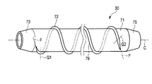
- It is a perspective view which shows roughly the structure of the spiral unit which concerns on 1st Embodiment.
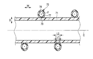
- It is sectional drawing which shows schematically the base tube and fin of the spiral unit which concern on 1st Embodiment in a cross section parallel to a longitudinal axis. It is a flowchart which shows the manufacturing method of the spiral unit which concerns on 1st Embodiment.
- FIG. 1 is a diagram illustrating an endoscope apparatus 1 that is an insertion apparatus according to the first embodiment.
- the endoscope apparatus 1 has a longitudinal axis C.
- One of the directions parallel to the longitudinal axis C (the direction of the arrow C1 in FIG. 1) is the distal direction, and the direction opposite to the distal direction (the direction of the arrow C2 in FIG. 1) is the proximal direction.
- the endoscope apparatus 1 includes an insertion portion (endoscope insertion portion) 2 extending along the longitudinal axis C and an operation portion (endoscope operation portion) 3 provided on the proximal direction side from the insertion portion 2. And comprising.
- the insertion portion 2 extends along the longitudinal axis C, and is inserted into a body cavity (intraluminal) when the endoscope apparatus 1 is used.
- the peripheral unit 10 includes an image processing unit 11 such as an image processor, a light source unit 12, a drive control unit 13 that is a control device including a CPU (central processing unit), an ASIC (application specific integrated circuit), a foot switch, A drive operation input unit 15 such as a button and a display unit 16 such as a monitor are provided.
- image processing unit 11 such as an image processor
- light source unit 12 a light source unit 12
- drive control unit 13 that is a control device including a CPU (central processing unit), an ASIC (application specific integrated circuit), a foot switch
- a drive operation input unit 15 such as a button
- a display unit 16 such as a monitor are provided.
- the insertion section 2 includes a distal rigid section 21 that forms the distal end of the insertion section, a bending section 22 provided on the proximal direction side from the distal rigid section 21, and a proximal end from the bending section 22.
- a first flexible tube section (first ⁇ flexible tube section) 23 provided on the direction side, and a second flexible tube portion (second flexible tube section) 25 provided on the proximal direction side of the first flexible tube portion 23.
- the curved portion 22 and the first serpentine tube portion 23 are connected by a first relay connection portion 26. Further, the first and second flexible pipe portions 23 and 25 are connected by a second relay connecting portion 27.
- a spiral unit 30 is provided on the outer peripheral side of the insertion portion 2.
- the spiral unit 30 extends along the longitudinal axis C between the first relay connection portion 26 and the second relay connection portion 27.
- the spiral unit 30 is attached to the insertion portion 2 in a state where the insertion portion 2 is inserted through the spiral unit 30.
- the spiral unit 30 can rotate in the direction around the longitudinal axis with respect to the insertion portion 2.
- FIG. 2 is a diagram illustrating a configuration of the second relay connection unit 27.
- 3 is a cross-sectional view taken along the line III-III in FIG. 2
- FIG. 4 is a cross-sectional view taken along the line IV-IV in FIG.
- a bending operation knob 33 which is a bending operation input unit to which a bending operation of the bending unit 22 is input, is provided on the outer surface of the operation unit 3.
- bending wires 35 ⁇ / b> A and 35 ⁇ / b> B extend along the longitudinal axis C in the insertion portion 2.
- proximal ends of the bending wires 35 ⁇ / b> A and 35 ⁇ / b> B are connected to a pulley (not shown) coupled to the bending operation knob 33.
- the distal ends of the bending wires 35 ⁇ / b> A and 35 ⁇ / b> B are connected to the distal end portion of the bending portion 22.
- the respective bending wires 35A and 35B are inserted through the corresponding coils 36A and 36B.
- the proximal ends of the coils 36 ⁇ / b> A and 36 ⁇ / b> B are fixed to the inner peripheral surface of the operation unit 3.
- the tips of the coils 36 ⁇ / b> A and 36 ⁇ / b> B are connected to the inner peripheral surface of the first relay connection portion 26.
- the two bending wires 35A and 35B are provided and the bending portion 22 can be bent in two directions.
- four bending wires are provided and the bending portion 22 is bent in four directions. It may be possible.
- an imaging cable 41, a light guide 42, and a treatment instrument channel tube 43 are extended along the longitudinal axis C in the insertion portion 2.
- An imaging element (not shown) for imaging a subject is provided inside the distal end rigid portion 21 (the distal end portion of the insertion portion 2).
- the imaging element images a subject through the observation window 46.
- the distal end of the imaging cable 41 is connected to the imaging device.
- the imaging cable 41 extends through the insertion unit 2, the operation unit 3, and the universal cable 5, and the base end is connected to the image processing unit 11 of the peripheral unit 10. Image processing of the subject image picked up by the image processing unit 11 is performed, and a subject image is generated. Then, the generated image of the subject is displayed on the display unit 16.
- the light guide 42 extends through the inside of the insertion portion 2, the inside of the operation portion 3, and the inside of the universal cable 5, and the base end is connected to the light source portion 12 of the peripheral unit 10.
- the light emitted from the light source unit 12 is guided by the light guide 42 and irradiated to the subject from the illumination window 47 of the distal end portion (the distal end rigid portion 21) of the insertion portion 2.
- a treatment instrument insertion section 48 into which a treatment instrument such as forceps is inserted is provided on the outer surface of the operation section 3.
- the treatment instrument channel tube 43 passes through the inside of the insertion section 2 and the inside of the operation section 3, and the proximal end is connected to the treatment instrument insertion section 48.
- the treatment instrument inserted from the treatment instrument insertion portion 48 passes through the inside of the treatment instrument channel tube 43 and protrudes from the opening 49 of the distal end rigid portion 21 toward the distal end. Then, the treatment with the treatment instrument is performed in a state where the treatment instrument protrudes from the opening 49 of the distal end rigid portion 21.
- a base member 51 is provided in the second relay connection portion 27.
- the proximal end portion of the first snake tube portion 23 is connected to the distal end portion of the base member 51 via the relay member 52.
- the first serpentine tube portion 23 and the second relay connection portion 27 are connected.
- the distal end portion of the second serpentine tube portion 25 is connected to the proximal end portion of the base member 51 through the relay member 53.
- the second serpentine tube portion 25 and the second relay connection portion 27 are connected.
- a hollow portion 55 is formed by the base member 51.
- the hollow portion 55 opens at the opening 56 toward the outer peripheral direction.
- a drive gear 57 and a relay gear 58 are attached to the base member 51.
- the drive gear 57 is disposed in the cavity 55, and the relay gear 58 is disposed in the vicinity of the opening 56 of the cavity 55.
- the drive gear 57 meshes with the relay gear 58.
- the drive gear 57 can rotate about the drive shaft G1, and the relay gear 58 can rotate about the gear shaft G2.
- a rotating cylindrical member 60 is attached to the base member 51 of the second relay connection portion 27.
- the rotating cylindrical member 60 is attached to the base member 51 in a state where the insertion portion 2 is inserted through the rotating cylindrical member 60.
- the rotating cylindrical member 60 is rotatable in the direction around the longitudinal axis with respect to the insertion portion 2 (base member 51).
- An inner peripheral gear portion 61 is provided on the inner peripheral surface of the rotating cylindrical member 60 over the entire circumference in the direction around the longitudinal axis.
- the inner peripheral gear portion 61 meshes with the relay gear 58.
- three inner rollers 62A to 62C are attached to the rotating cylindrical member 60.
- the inner rollers 62A to 62C are arranged at substantially equal intervals in the direction around the longitudinal axis.
- Each inner roller 62A-62C has a corresponding roller shaft (R1-R3).
- Each of the inner rollers 62A to 62C is rotatable with respect to the rotating cylindrical member 60 about the corresponding roller shaft (R1 to R3). Further, the inner rollers 62A to 62C can rotate in the direction around the longitudinal axis with respect to the insertion portion 2 (base member 51) integrally with the rotating cylindrical member 60.
- a cylindrical cover member 63 is coated on the outer circumferential direction side of the rotating cylindrical member 60 and the inner rollers 62A to 62C.
- the front end of the cover member 63 is fixed to the base member 51 via a locking member 65A, and the base end of the cover member 63 is fixed to the base member 51 via a locking member 65B.
- the base member 51 and the cover member 63 are kept liquid-tight at the fixed position at the distal end of the cover member 63 and the fixed position at the proximal end of the cover member 63. This prevents the liquid from flowing into the cavity 55, the rotating cylindrical member 60, and the inner rollers 62A to 62C located on the inner circumferential direction side of the cover member 63.
- cover member 63 protrudes in the outer peripheral direction at a portion where the inner rollers 62A to 62C are located in the direction around the longitudinal axis. Note that the cover member 63 is fixed with respect to the insertion portion 2, and the rotating cylindrical member 60 can rotate about the longitudinal axis with respect to the cover member 63.
- a member insertion portion 65 is provided on the outer surface of the operation portion 3.
- a motor 66 that is a driving member is attached to the member insertion portion 65.
- One end of a motor cable 67 is connected to the motor 66.
- the other end of the motor cable 67 is connected to the drive control unit 13 of the peripheral unit 10.
- a drive shaft 68 that is a linear member extends along the drive axis G ⁇ b> 1 inside the second serpentine tube portion 25 of the insertion portion 2.
- the tip of the drive shaft 68 is connected to the drive gear 57.
- the base end of the drive shaft 68 is connected to a motor 66 attached to the member insertion portion 65.
- the tip of a member channel tube 69 is connected to the base member 51.
- the base end of the member channel tube 69 is connected to the member insertion portion 65.
- the drive shaft 68 extends through the interior of the member channel tube 69.
- the drive control unit 13 supplies power to the motor 66 via the motor cable 67 by the operation input from the drive operation input unit 15, and controls the drive of the motor 66.
- a rotational driving force for rotating the spiral unit 30 is generated, and the driving shaft 68 and the driving gear 57 rotate around the driving shaft G1.
- the drive shaft G ⁇ b> 1 passes through the centers of the drive gear 57 and the drive shaft 68, and is substantially parallel to the longitudinal axis C inside the second serpentine tube portion 25.
- the drive shaft G ⁇ b> 1 is bent toward the member insertion portion 65 inside the operation portion 3.
- Rotation of the drive gear 57 causes the relay gear 58 to rotate about the gear shaft G ⁇ b> 2, and the rotational driving force is transmitted to the rotating cylindrical member 60 via the relay gear 58.
- the rotating cylindrical member 60 rotates in the direction around the longitudinal axis, and the inner rollers 62A to 62C move in the direction around the longitudinal axis with respect to the insertion portion 2 and the cover member 63.
- FIG. 5 is a diagram showing the configuration of the spiral unit 30.
- the spiral unit 30 includes a base tube 71 extending along the longitudinal axis C.
- the base tube 71 is formed from a thermoplastic first resin.
- a fin 72 is attached to the outer peripheral surface of the base tube 71.
- the fins 72 are formed from a thermoplastic second resin such as polyvinyl chloride (PVC).
- the fin 72 has a fin axis F extending in a spiral shape with the longitudinal axis C as the center, and the fin 72 is provided along the fin axis F.
- the first resin forming the base tube 71 and the second resin forming the fins 72 may be the same resin or different resins.
- a cylindrical tip side taper portion 73 is provided on the tip direction side of the base tube 71.
- the distal end side taper portion 73 is formed in a tapered shape whose outer diameter decreases toward the distal direction side.
- a cylindrical base end side tapered portion 75 is provided on the base end direction side of the base tube 71.
- the proximal end side taper portion 75 is formed in a tapered shape whose outer diameter decreases toward the proximal direction side.
- the fin 72 extends only on the outer peripheral surface of the base tube 71 and does not extend on the outer peripheral surface of the distal end side tapered portion 73 and the outer peripheral surface of the proximal end side tapered portion 75.
- 72 may extend to the outer peripheral surface of the distal end side tapered portion 73 and the outer peripheral surface of the proximal end side tapered portion 75.
- outer rollers 76A to 76F are attached to the inner peripheral surface of the base end side taper portion 75.
- the outer rollers 76A to 76F are located on the outer peripheral direction side of the cover member 63.
- the inner roller 62A is positioned between the outer roller 76A and the outer roller 76B, and the inner roller 62B is positioned between the outer roller 76C and the outer roller 76D.
- the inner roller 62C is located between the outer roller 76E and the outer roller 76F in the direction around the longitudinal axis.
- Each of the outer rollers 76A to 76F has a corresponding roller shaft (P1 to P6).
- Each of the outer rollers 76A to 76F is rotatable with respect to the cover member 63 and the proximal end side taper portion 75 around the corresponding roller shaft (P1 to P6). Further, the outer rollers 76A to 76F can rotate in the direction around the longitudinal axis with respect to the insertion portion 2 (base member 51) integrally with the spiral unit 30.
- the inner roller 62A presses the outer roller 76A or the outer roller 76B.
- the inner roller 62B presses the outer roller 76C or the outer roller 76D
- the inner roller 62C presses the outer roller 76E or the outer roller 76F.
- the rotational driving force is transmitted from the inner rollers 62A to 62C to the spiral unit 30, and the spiral unit 30 including the base tube 71 and the fins 72 rotates in one of the directions around the longitudinal axis with respect to the insertion portion 2 and the cover member 63. To do.
- the inner rollers 62A to 62C rotate about the corresponding roller shafts (R1 to R3), so that the friction between the inner rollers 62A to 62C and the cover member 63 is reduced.
- the outer rollers 76A to 76F rotate around the corresponding roller shafts (P1 to P6), the friction between the outer rollers 76A to 76F and the cover member 63 is reduced. Therefore, the rotational driving force is appropriately transmitted from the inner rollers 62A to 62C to the spiral unit 30, and the spiral unit 30 is appropriately rotated.
- FIG. 6 is a view of the spiral unit 30 cut along a cross section parallel to the longitudinal axis C.
- the fin 72 is cut in a cross section perpendicular to the fin axis F.
- the fin 72 includes a hollow portion 77 and is formed in a tube shape extending along the fin axis F. Therefore, in the hollow portion 77, the cavity portion 78 extends along the fin axis F.
- the cavity portion 78 also extends in a spiral shape with the longitudinal axis C as the center.
- the fin axis F coincides with the central axis of the cavity 78.
- a strip portion 79 is provided on the inner circumferential direction side from the cavity portion 78.
- the band portion 79 extends along the fin axis F. That is, the band 79 extends in a spiral shape with the longitudinal axis C as the center.
- the fin 72 is bonded to the outer peripheral surface of the base tube 71 with a band portion 79.
- a magnetic material such as iron, ferrite, stainless steel, or ceramic is mixed in the second resin forming the fins 72.
- the direction toward the longitudinal axis C is the inner circumferential direction
- the direction away from the longitudinal axis C is the outer circumferential direction.
- the outer circumferential direction and the inner circumferential direction are the radial direction of the base tube 71 (the direction of the arrow D in FIG. 6).
- the direction perpendicular to the fin axis F and perpendicular to the radial direction of the base tube 71 is the fin width direction (the direction of the arrow W in FIG. 6).
- the band width dimension L1 of the band part 79 in the fin width direction is smaller than the cavity width dimension L2 of the cavity part 78 in the fin width direction.
- the protrusion amount of the fin 72 in the outer peripheral direction from the outer peripheral surface of the base tube 71 is constant between the distal end side reference position Q1 and the proximal end side reference position Q2.
- the protrusion amount of the fin 72 from the outer peripheral surface of the base tube 71 becomes smaller toward the distal direction.
- the protrusion amount of the fin 72 from the outer peripheral surface of the base tube 71 becomes smaller toward the base end direction.
- the protrusion amount of the fin 72 from the outer peripheral surface of the base tube 71 is maximized between the distal end side reference position Q1 and the proximal end side reference position Q2. Further, the band portion 79 extends along the fin axis F between the distal end side reference position Q1 and the proximal end side reference position Q2.
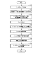
- FIG. 7 is a flowchart showing a method for manufacturing the spiral unit 30.
- the base tube 71 is formed from the thermoplastic first resin along the longitudinal axis C (step S101).
- the base tube 71 is formed by extrusion molding.
- the front end side taper part 73 and the base end side taper part 75 are formed (step S102), and the front end side taper part 73 and the base end side taper part 75 are connected to the base tube 71 (step S103).
- the distal end side tapered portion 73 and the proximal end side tapered portion 75 are separate members from the base tube 71, but may be formed integrally with the base tube 71.
- the fin 72 is formed along the fin axis F from the second thermoplastic resin (step S104).
- the fins 72 are formed by two-color extrusion molding. By performing the two-color molding, a portion other than the belt portion 79 including the magnetic material and the belt portion 79 not including the magnetic material is easily formed.
- a band portion 79 extends along the fin axis F.
- FIG. 8 shows an example of the fin 72 in a state before being wound around the outer peripheral surface of the base tube 71.
- a tip-side inclined surface 81 that is inclined with respect to the fin axis F in a state of extending in the tip direction along the fin axis F from the tip of the band 79 is provided at the tip of the fin 72.
- the base-side inclined surface 82 that inclines with respect to the fin axis F in a state of extending in the base end direction along the fin axis F from the base end of the band portion 79.
- the distal side inclined surface 81 and the proximal side inclined surface 82 are formed in a surface shape corresponding to the curved surface shape of the outer peripheral surface of the base tube 71.
- FIG. 9 shows another example of the fin 72 in a state before being wound around the outer peripheral surface of the base tube 71.
- a tip-side inclined surface 81 that is inclined with respect to the fin axis F in a state of extending in the tip direction along the fin axis F from the tip of the band 79 is provided at the tip of the fin 72. Further, at the base end portion of the fin 72, the base-side inclined surface 82 that inclines with respect to the fin axis F in a state of extending in the base end direction along the fin axis F from the base end of the band portion 79. Is provided.
- the distal side inclined surface 81 and the proximal side inclined surface 82 are formed in a surface shape corresponding to the curved surface shape of the outer peripheral surface of the base tube 71. As shown in FIG.
- the fin axis F in the fin 72 in a state before being wound around the outer peripheral surface of the base tube 71, the fin axis F may be extended linearly. As shown in FIG. 9, the fin axis F may be spirally extended in the fin 72 in a state before being wound around the outer peripheral surface of the base tube 71.
- FIG. 10 is a diagram illustrating a state in which the fin 72 is wound around the outer peripheral surface of the base tube 71. As shown in FIG. 10, the fin 72 is wound in a state where the band portion 79 is in contact with the outer peripheral surface of the base tube 71.
- a distal end inclined surface 81 that is inclined with respect to the fin axis F is formed at the distal end portion of the fin 72
- a proximal end inclined surface 82 that is inclined with respect to the fin axis F is formed at the proximal end portion of the fin 72. Is formed.
- the distal end side inclined surface 81 and the proximal end side inclined surface 82 are formed by cutting the fin 72 in a cross section inclined with respect to the fin axis F.
- the tip-side inclined surface 81 that contacts the outer peripheral surface of the base tube 71 is inclined so as to be positioned on the tip direction side as the distance from the band portion 79 increases.
- the boundary between the tip side inclined surface 81 and the band 79 is the tip side reference position Q1.
- the base-side inclined surface 82 that contacts the outer peripheral surface of the base tube 71 is inclined so as to be located on the base-end direction side as the distance from the band portion 79 increases.
- the boundary between the base end side inclined surface 82 and the band 79 is the base end side reference position Q2.
- the band portion 79 is extended from the distal end side reference position Q1 to the proximal end side reference position Q2, and the fin 72 is located between the distal end side reference position Q1 and the proximal end side reference position Q2 of the base tube 71. It is in contact with the outer peripheral surface.
- electromagnetic waves are applied to the fins 72 wound around the outer peripheral surface of the base tube 71 (step S106).
- the magnetic body vibrates and heat is generated in the band 79.
- the second resin melts in the band 79 (step S107).
- the first resin may be melted by the generated heat at the contact portion with the band portion 79 of the base tube 71.
- the second resin does not melt in the portion other than the band portion 79 of the fin 72 that does not include the magnetic material.
- the intensity of the electromagnetic wave is adjusted to such an intensity that the magnetic material generates an amount of heat suitable for bonding the band 79 to the base tube 71.
- the second resin melted in the band 79 is cooled to coagulate the second resin (step S108).
- the first resin is melted at the contact portion of the base tube 71 with the band portion 79
- the melted first resin also solidifies.
- the band portion 79 of the fin 72 adheres to the outer peripheral surface of the base tube 71 (step S109).
- the distal end side inclined surface 81 and the proximal end inclined surface 82 are bonded to the outer peripheral surface of the base tube 71 via an adhesive or the like.
- the tip-side inclined surface 81 By adhering the tip-side inclined surface 81, the amount of protrusion of the fin 72 in the outer peripheral direction decreases toward the tip direction on the tip direction side from the tip-side reference position Q1.
- the base-side inclined surface 82 By bonding the base-side inclined surface 82, the fin portion 72 in the radial direction (outer peripheral direction) of the base tube 71 toward the base end direction on the base end direction side from the base end side reference position Q2. The protruding amount of becomes smaller.
- the magnetic body is vibrated by irradiating the electromagnetic wave, and the second resin is melted by the band 79, so that the band 79 of the fin 72 is attached to the outer peripheral surface of the base tube 71.
- the band portion 79 is easily wrapped around the outer peripheral surface of the base tube 71 by winding the fins 72 around the outer peripheral surface of the base tube 71 with the band portion 79 in contact with the outer peripheral surface of the base tube 71. Can be glued. Therefore, in the fin 72, the band portion 79 may be provided at a position where the fin 72 can contact the outer peripheral surface of the base tube 71.
- the bonding surface of the fin 72 (band portion 79) with the base tube 71 is planar. There is no need. Accordingly, the shape of the fin 72 is not limited as long as the band portion 79 can contact the outer peripheral surface of the base tube 71.
- the second resin of the belt portion 79 is melted by heat generated by the vibration of the magnetic material, it is not necessary to provide a filler member or the like at the bonding portion between the fin 72 and the base tube 71.
- zone part 79 containing a magnetic body is easily formed by two-color extrusion molding. For this reason, in manufacturing the spiral unit 30, the time is shortened and the cost is reduced.
- any shape of the fin 72 can be easily and safely bonded to the outer peripheral surface of the base tube 71. Thereby, the spiral unit 30 can be manufactured easily.
- the band width dimension L1 of the band part 79 in the fin width direction is smaller than the cavity width dimension L2 of the cavity part 78 in the fin width direction.
- the endoscope apparatus 1 that is an insertion apparatus in which the spiral unit 30 is used will be described.
- the insertion unit 2 is inserted into a lumen, for example, with the spiral unit 30 attached to the insertion unit 2.
- the motor 66 is driven to rotate the spiral unit 30 in one of the directions around the longitudinal axis with respect to the insertion portion 2 as described above.
- the spiral unit 30 (the base tube 71 and the fin 72) is provided on one side in the direction around the longitudinal axis in a state where the fin 72 extending spirally around the longitudinal axis C receives a pressing force from the lumen wall in the inner circumferential direction.
- a propulsive force in the distal direction acts on the insertion portion 2.
- the spiral unit 30 (the base tube 71 and the fin 72) is rotated in the other direction around the longitudinal axis, thereby propelling in the proximal direction.
- a force acts on the insertion portion 2.
- the insertion force of the insertion portion 2 in the lumen is improved by the propelling force in the distal direction, and the removal property of the insertion portion 2 in the lumen is improved by the propelling force in the proximal direction.
- the fin 72 since the fin 72 is formed in a tube shape including the hollow portion 77, the fin 72 has moderate elasticity. Since the fin 72 has an appropriate elasticity, generation of torsion and twist in the fin 72 is effectively prevented in a state in which a pressing force acts on the fin 72 in the inner circumferential direction from the lumen wall. The Since the twist and the twist in the fin 72 do not occur, the propulsive force in the distal direction or the proximal direction is appropriately applied to the insertion portion 2 by rotating the spiral unit 30. Therefore, by rotating the spiral unit 30, the insertion portion 2 is inserted and removed appropriately from the lumen.
- the fin 72 is formed in a tube shape having the hollow portion 77, the fin 72 has appropriate flexibility. For this reason, even when the spiral unit 30 is not rotated, the fin 72 is easily bent by the pressing force from the lumen wall by moving the insertion portion 2 in the proximal direction in the lumen. Therefore, even when the spiral unit 30 cannot rotate due to a failure or the like, the insertion portion 2 can be easily removed from the lumen.
- the fin 72 is formed in the tube shape provided with the hollow part 77, it is not restricted to this.
- the fins 72 may be formed in a column shape instead of being hollow.
- the band 72 in which the magnetic material is mixed into the second resin is provided on the fin 72.
- the fin 72 has a fin axis F extending in a spiral shape with the longitudinal axis C as the center, and the band portion 79 extends along the fin axis F. ing.
- the fin 72 is bonded to the outer peripheral surface of the base tube 71 with a band portion 79. That is, the band portion 79 is provided at a position where the fin 72 adheres to the outer peripheral surface of the base tube 71.
- the motor 66 that is a driving member is attached to the member insertion portion 65 of the operation portion 3, but the present invention is not limited to this.
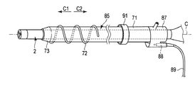
- the motor 88 which is a drive member is provided in the spiral unit 85 shown in FIG. 12 as a 2nd modification.
- the spiral unit 85 of this modification includes a proximal-side cylindrical portion 87 instead of the proximal-side tapered portion 75.
- the insertion portion 2 is inserted into the proximal end tubular portion 87, and the proximal end tubular portion 87 is fixed to the insertion portion 2.
- a motor 88 is attached to the proximal end side tubular portion 87.
- One end of a motor cable 89 is connected to the motor 88.
- the base tube 71 is connected to the distal direction side of the proximal end tubular portion 87, and the fin 72 is attached to the outer peripheral surface of the distal end portion of the base tube 71.
- a tip side taper portion 73 is provided on the tip direction side of the base tube 71.
- the fins 72 are provided only on the outer peripheral surface of the distal end portion of the base tube 71, and the fins 72 are provided over the entire length of the outer peripheral surface of the base tube 71 in the direction parallel to the longitudinal axis C. Absent.
- a cylindrical holding portion 91 is provided on the outer peripheral direction side of the base end portion of the base tube 71.
- the base tube 71, the fin 72, and the distal end side taper portion 73 are rotatable around the longitudinal axis with respect to the proximal end side tubular portion 87.
- the base tube 71, the fin 72, and the distal end side taper portion 73 are rotatable in the direction around the longitudinal axis with respect to the insertion portion 2. Therefore, in the present modification, the entire spiral unit 85 is not rotatable about the longitudinal axis with respect to the insertion portion 2, and a part of the spiral unit 85 including the base tube 71 and the fins 72 is longitudinal with respect to the insertion portion 2. It can rotate in the direction of rotation.
- the motor 88 is supplied to the motor 88 via the motor cable 89 and the motor 88 is driven to generate a rotational driving force that rotates the base tube 71 and the fins 72.
- the generated rotational driving force is transmitted to the base tube 71 via a gear (not shown) attached to the proximal end side cylindrical portion 87, and the base tube 71, the fin 72, and the distal end side tapered portion 73 are inserted into the insertion portion. 2 in the direction around the longitudinal axis.
- the fin 72 is provided with a band portion 79 in which a magnetic material is mixed into the second resin.
- the motor (66; 88) is driven by electric power to rotate the base tube 71 and the fin 72 around the longitudinal axis.
- a driving force is generated, but is not limited to this.
- a manual operation knob 97 may be provided in the spiral unit 95 instead of the motor (66; 88).
- the spiral unit 95 is provided with a base tube 71, fins 72, a distal end side tapered portion 73, a proximal end side cylindrical portion 87, and a holding portion 91. It has been.
- a manual operation knob 97 is provided on the base end direction side of the base end side tubular portion 87.
- the manual operation knob 97 is rotatable integrally with the base tube 71, the fin 72, and the distal end side tapered portion 73 in the direction around the longitudinal axis with respect to the proximal end side cylindrical portion 87. Therefore, the manual operation knob 97 can rotate about the longitudinal axis relative to the insertion portion 2 together with the base tube 71, the fins 72, and the distal end side taper portion 73.
- the manual operation knob 97 is manually rotated in one direction around the longitudinal axis to generate a rotational driving force that rotates the base tube 71 and the fins 72.
- the generated rotational driving force is transmitted to the base tube 71, and the base tube 71, the fin 72, and the distal end side taper portion 73 rotate around the longitudinal axis with respect to the insertion portion 2.
- the fin 72 is provided with a band portion 79 in which a magnetic material is mixed into the second resin.
- the endoscope apparatus 1 is described as an example of the insertion apparatus, but the insertion apparatus is not limited to the endoscope apparatus 1.
- the aforementioned spiral unit (30; 85; 95) may be attached to the insertion portion of the manipulator device that is an insertion device.
- the spiral unit (30; 85; 95) extends along the longitudinal axis C, and extends in a spiral shape with the base tube 71 formed from the thermoplastic first resin and the longitudinal axis C as the center.
- a fin 72 that is attached to the outer peripheral surface of the base tube 71 along the fin axis F and is formed from a thermoplastic second resin may be provided.
- the fin 72 should just be provided in the state bonded to the outer peripheral surface of the base tube 71, and should be provided with the belt
Landscapes
- Health & Medical Sciences (AREA)
- Life Sciences & Earth Sciences (AREA)
- Engineering & Computer Science (AREA)
- Surgery (AREA)
- Physics & Mathematics (AREA)
- Mechanical Engineering (AREA)
- Veterinary Medicine (AREA)
- Heart & Thoracic Surgery (AREA)
- Animal Behavior & Ethology (AREA)
- General Health & Medical Sciences (AREA)
- Public Health (AREA)
- Biomedical Technology (AREA)
- Nuclear Medicine, Radiotherapy & Molecular Imaging (AREA)
- Medical Informatics (AREA)
- Molecular Biology (AREA)
- Optics & Photonics (AREA)
- Biophysics (AREA)
- Pathology (AREA)
- Radiology & Medical Imaging (AREA)
- Electromagnetism (AREA)
- Manufacturing & Machinery (AREA)
- General Physics & Mathematics (AREA)
- Astronomy & Astrophysics (AREA)
- Robotics (AREA)
- Toxicology (AREA)
- Hematology (AREA)
- Anesthesiology (AREA)
- Pulmonology (AREA)
- Endoscopes (AREA)
- Instruments For Viewing The Inside Of Hollow Bodies (AREA)
Abstract
Priority Applications (4)
| Application Number | Priority Date | Filing Date | Title |
|---|---|---|---|
| EP14818238.9A EP3015049B1 (fr) | 2013-06-26 | 2014-06-10 | Unité spiralée, dispositif d'insertion, et procédé de fabrication d'unité spiralée |
| CN201480036634.0A CN105338877B (zh) | 2013-06-26 | 2014-06-10 | 螺旋单元、插入装置和螺旋单元的制造方法 |
| JP2015522307A JP5816775B2 (ja) | 2013-06-26 | 2014-06-10 | スパイラルユニット、挿入装置、及びスパイラルユニットの製造方法 |
| US14/974,752 US9538904B2 (en) | 2013-06-26 | 2015-12-18 | Spiral unit, insertion apparatus, and manufacturing method of spiral unit |
Applications Claiming Priority (2)
| Application Number | Priority Date | Filing Date | Title |
|---|---|---|---|
| US201361839431P | 2013-06-26 | 2013-06-26 | |
| US61/839,431 | 2013-06-26 |
Related Child Applications (1)
| Application Number | Title | Priority Date | Filing Date |
|---|---|---|---|
| US14/974,752 Continuation US9538904B2 (en) | 2013-06-26 | 2015-12-18 | Spiral unit, insertion apparatus, and manufacturing method of spiral unit |
Publications (1)
| Publication Number | Publication Date |
|---|---|
| WO2014208332A1 true WO2014208332A1 (fr) | 2014-12-31 |
Family
ID=52141677
Family Applications (1)
| Application Number | Title | Priority Date | Filing Date |
|---|---|---|---|
| PCT/JP2014/065376 Ceased WO2014208332A1 (fr) | 2013-06-26 | 2014-06-10 | Unité spiralée, dispositif d'insertion, et procédé de fabrication d'unité spiralée |
Country Status (5)
| Country | Link |
|---|---|
| US (1) | US9538904B2 (fr) |
| EP (1) | EP3015049B1 (fr) |
| JP (1) | JP5816775B2 (fr) |
| CN (1) | CN105338877B (fr) |
| WO (1) | WO2014208332A1 (fr) |
Cited By (4)
| Publication number | Priority date | Publication date | Assignee | Title |
|---|---|---|---|---|
| CN104656241A (zh) * | 2015-03-16 | 2015-05-27 | 北京京金吾高科技有限公司 | 一种狭小空间观测仪 |
| WO2016194413A1 (fr) * | 2015-06-03 | 2016-12-08 | オリンパス株式会社 | Unité de montage |
| WO2016194412A1 (fr) * | 2015-06-05 | 2016-12-08 | オリンパス株式会社 | Unité de montage |
| WO2017002415A1 (fr) * | 2015-07-02 | 2017-01-05 | オリンパス株式会社 | Instrument d'insertion et dispositif d'insertion |
Families Citing this family (5)
| Publication number | Priority date | Publication date | Assignee | Title |
|---|---|---|---|---|
| CN109068952B (zh) * | 2016-06-13 | 2020-11-13 | 奥林巴斯株式会社 | 插入设备、安装器具以及驱动力传递单元 |
| WO2018174241A1 (fr) * | 2017-03-24 | 2018-09-27 | 朝日インテック株式会社 | Dilatateur |
| EP3804640A1 (fr) * | 2018-05-24 | 2021-04-14 | Asahi Intecc Co., Ltd. | Dilatateur |
| US11647896B2 (en) * | 2019-03-28 | 2023-05-16 | Olympus Corporation | Rollerless tubular connector for transferring rotative force from insertion section of endoscope to spiral tube |
| PL439266A1 (pl) * | 2021-10-20 | 2023-04-24 | Extrudan Spółka Z Ograniczoną Odpowiedzialnością | Sposoby wytworzenia elastycznego spiralnego przewodu medycznego oraz przewód medyczny składający się z części rurowej oraz oplotu |
Citations (6)
| Publication number | Priority date | Publication date | Assignee | Title |
|---|---|---|---|---|
| JPH06315978A (ja) * | 1994-04-08 | 1994-11-15 | Dainippon Plastics Co Ltd | プラスチックス螺旋巻き管及びその製造方法 |
| JPH07117132A (ja) * | 1993-10-22 | 1995-05-09 | Mitsui Petrochem Ind Ltd | コルゲート管接続用のチューブ及び該チューブを用いた コルゲート管の接続方法 |
| JP2004232674A (ja) * | 2003-01-28 | 2004-08-19 | Kubota Corp | インサーション工法 |
| US20120002981A1 (en) | 2010-06-30 | 2012-01-05 | Samsung Electronics Co., Ltd. | Management server and management method thereof |
| WO2012137363A1 (fr) * | 2011-04-08 | 2012-10-11 | オリンパスメディカルシステムズ株式会社 | Endoscope |
| JP2013525076A (ja) * | 2010-05-03 | 2013-06-20 | オリンパス エンド テクノロジー アメリカ インコーポレイテッド | 回転前進式カテーテル挿入システム |
Family Cites Families (6)
| Publication number | Priority date | Publication date | Assignee | Title |
|---|---|---|---|---|
| US5416303A (en) * | 1994-07-07 | 1995-05-16 | The Proctor & Gamble Company | Method for induction sealing an inner bag to an outer container |
| JP2007306944A (ja) * | 2005-01-21 | 2007-11-29 | Olympus Corp | 内視鏡及び内視鏡用医療器具並びにその表示方法 |
| US8235942B2 (en) * | 2005-05-04 | 2012-08-07 | Olympus Endo Technology America Inc. | Rotate-to-advance catheterization system |
| JP2007167125A (ja) * | 2005-12-19 | 2007-07-05 | Olympus Medical Systems Corp | カプセル内視鏡及びその製造方法 |
| JP5250185B2 (ja) * | 2006-05-29 | 2013-07-31 | 積水フーラー株式会社 | 高周波電磁誘導加熱型接着剤を用いた積層体の積層方法および被着体の分離方法 |
| JP2008259634A (ja) * | 2007-04-11 | 2008-10-30 | Olympus Corp | 内視鏡用可撓管と環状連結部材との連結構造 |
-
2014
- 2014-06-10 WO PCT/JP2014/065376 patent/WO2014208332A1/fr not_active Ceased
- 2014-06-10 EP EP14818238.9A patent/EP3015049B1/fr active Active
- 2014-06-10 CN CN201480036634.0A patent/CN105338877B/zh active Active
- 2014-06-10 JP JP2015522307A patent/JP5816775B2/ja active Active
-
2015
- 2015-12-18 US US14/974,752 patent/US9538904B2/en active Active
Patent Citations (6)
| Publication number | Priority date | Publication date | Assignee | Title |
|---|---|---|---|---|
| JPH07117132A (ja) * | 1993-10-22 | 1995-05-09 | Mitsui Petrochem Ind Ltd | コルゲート管接続用のチューブ及び該チューブを用いた コルゲート管の接続方法 |
| JPH06315978A (ja) * | 1994-04-08 | 1994-11-15 | Dainippon Plastics Co Ltd | プラスチックス螺旋巻き管及びその製造方法 |
| JP2004232674A (ja) * | 2003-01-28 | 2004-08-19 | Kubota Corp | インサーション工法 |
| JP2013525076A (ja) * | 2010-05-03 | 2013-06-20 | オリンパス エンド テクノロジー アメリカ インコーポレイテッド | 回転前進式カテーテル挿入システム |
| US20120002981A1 (en) | 2010-06-30 | 2012-01-05 | Samsung Electronics Co., Ltd. | Management server and management method thereof |
| WO2012137363A1 (fr) * | 2011-04-08 | 2012-10-11 | オリンパスメディカルシステムズ株式会社 | Endoscope |
Cited By (12)
| Publication number | Priority date | Publication date | Assignee | Title |
|---|---|---|---|---|
| CN104656241A (zh) * | 2015-03-16 | 2015-05-27 | 北京京金吾高科技有限公司 | 一种狭小空间观测仪 |
| WO2016194413A1 (fr) * | 2015-06-03 | 2016-12-08 | オリンパス株式会社 | Unité de montage |
| JPWO2016194413A1 (ja) * | 2015-06-03 | 2017-06-22 | オリンパス株式会社 | 装着ユニット |
| WO2016194412A1 (fr) * | 2015-06-05 | 2016-12-08 | オリンパス株式会社 | Unité de montage |
| JPWO2016194412A1 (ja) * | 2015-06-05 | 2017-06-22 | オリンパス株式会社 | 装着ユニット |
| CN107529951A (zh) * | 2015-06-05 | 2018-01-02 | 奥林巴斯株式会社 | 安装单元 |
| CN107529951B (zh) * | 2015-06-05 | 2019-01-04 | 奥林巴斯株式会社 | 安装单元 |
| WO2017002415A1 (fr) * | 2015-07-02 | 2017-01-05 | オリンパス株式会社 | Instrument d'insertion et dispositif d'insertion |
| JP6116783B1 (ja) * | 2015-07-02 | 2017-04-19 | オリンパス株式会社 | 挿入機器および挿入装置 |
| CN106999015A (zh) * | 2015-07-02 | 2017-08-01 | 奥林巴斯株式会社 | 插入设备和插入装置 |
| CN106999015B (zh) * | 2015-07-02 | 2018-11-27 | 奥林巴斯株式会社 | 插入设备和插入装置 |
| US10285570B2 (en) | 2015-07-02 | 2019-05-14 | Olympus Corporation | Insertion instrument and insertion device |
Also Published As
| Publication number | Publication date |
|---|---|
| EP3015049A4 (fr) | 2017-03-08 |
| EP3015049A1 (fr) | 2016-05-04 |
| CN105338877A (zh) | 2016-02-17 |
| US20160100743A1 (en) | 2016-04-14 |
| JPWO2014208332A1 (ja) | 2017-02-23 |
| EP3015049B1 (fr) | 2018-08-01 |
| CN105338877B (zh) | 2017-06-06 |
| JP5816775B2 (ja) | 2015-11-18 |
| US9538904B2 (en) | 2017-01-10 |
Similar Documents
| Publication | Publication Date | Title |
|---|---|---|
| JP5816775B2 (ja) | スパイラルユニット、挿入装置、及びスパイラルユニットの製造方法 | |
| US11850375B2 (en) | Catheter devices and methods for making them | |
| US9204784B2 (en) | Attachment unit and endoscope | |
| JP5802856B2 (ja) | 挿入装置 | |
| JP5857164B2 (ja) | 挿入機器、回転ユニット及び挿入装置 | |
| WO2015019675A1 (fr) | Dispositif d'introduction | |
| US20160058971A1 (en) | Catheter devices and methods for making them | |
| JP5829356B2 (ja) | スパイラルキャップ、キャップユニット、スパイラルユニット、及び、導入装置 | |
| EP2476452B1 (fr) | Dispositif d'introduction intra-canalair | |
| CN103648358B (zh) | 插入装置、旋转筒状部件和驱动单元 | |
| CN112004452B (zh) | 螺旋管和内窥镜 | |
| CN103201066B (zh) | 内窥镜用激光焊接方法及内窥镜用激光焊接构件 | |
| JP5179600B2 (ja) | 内視鏡挿入補助装置 | |
| JP2006020942A (ja) | 体内挿入用器具およびその製造方法 | |
| EP3320826A1 (fr) | Dispositif d'insertion | |
| WO2018066274A1 (fr) | Endoscope | |
| JP2012183221A (ja) | 自己推進装置 |
Legal Events
| Date | Code | Title | Description |
|---|---|---|---|
| WWE | Wipo information: entry into national phase |
Ref document number: 201480036634.0 Country of ref document: CN |
|
| 121 | Ep: the epo has been informed by wipo that ep was designated in this application |
Ref document number: 14818238 Country of ref document: EP Kind code of ref document: A1 |
|
| ENP | Entry into the national phase |
Ref document number: 2015522307 Country of ref document: JP Kind code of ref document: A |
|
| NENP | Non-entry into the national phase |
Ref country code: DE |
|
| WWE | Wipo information: entry into national phase |
Ref document number: 2014818238 Country of ref document: EP |