WO2014208372A1 - Procédé de soudage et dispositif de soudage - Google Patents
Procédé de soudage et dispositif de soudage Download PDFInfo
- Publication number
- WO2014208372A1 WO2014208372A1 PCT/JP2014/065805 JP2014065805W WO2014208372A1 WO 2014208372 A1 WO2014208372 A1 WO 2014208372A1 JP 2014065805 W JP2014065805 W JP 2014065805W WO 2014208372 A1 WO2014208372 A1 WO 2014208372A1
- Authority
- WO
- WIPO (PCT)
- Prior art keywords
- welding
- main
- base material
- steering member
- component
- Prior art date
- Legal status (The legal status is an assumption and is not a legal conclusion. Google has not performed a legal analysis and makes no representation as to the accuracy of the status listed.)
- Ceased
Links
Images


Classifications
-
- B—PERFORMING OPERATIONS; TRANSPORTING
- B23—MACHINE TOOLS; METAL-WORKING NOT OTHERWISE PROVIDED FOR
- B23K—SOLDERING OR UNSOLDERING; WELDING; CLADDING OR PLATING BY SOLDERING OR WELDING; CUTTING BY APPLYING HEAT LOCALLY, e.g. FLAME CUTTING; WORKING BY LASER BEAM
- B23K9/00—Arc welding or cutting
- B23K9/12—Automatic feeding or moving of electrodes or work for spot or seam welding or cutting
-
- B—PERFORMING OPERATIONS; TRANSPORTING
- B23—MACHINE TOOLS; METAL-WORKING NOT OTHERWISE PROVIDED FOR
- B23K—SOLDERING OR UNSOLDERING; WELDING; CLADDING OR PLATING BY SOLDERING OR WELDING; CUTTING BY APPLYING HEAT LOCALLY, e.g. FLAME CUTTING; WORKING BY LASER BEAM
- B23K37/00—Auxiliary devices or processes, not specially adapted for a procedure covered by only one of the other main groups of this subclass
- B23K37/02—Carriages for supporting the welding or cutting element
- B23K37/0247—Driving means
-
- B—PERFORMING OPERATIONS; TRANSPORTING
- B23—MACHINE TOOLS; METAL-WORKING NOT OTHERWISE PROVIDED FOR
- B23K—SOLDERING OR UNSOLDERING; WELDING; CLADDING OR PLATING BY SOLDERING OR WELDING; CUTTING BY APPLYING HEAT LOCALLY, e.g. FLAME CUTTING; WORKING BY LASER BEAM
- B23K37/00—Auxiliary devices or processes, not specially adapted for a procedure covered by only one of the other main groups of this subclass
- B23K37/04—Auxiliary devices or processes, not specially adapted for a procedure covered by only one of the other main groups of this subclass for holding or positioning work
- B23K37/0426—Fixtures for other work
- B23K37/0435—Clamps
-
- B—PERFORMING OPERATIONS; TRANSPORTING
- B25—HAND TOOLS; PORTABLE POWER-DRIVEN TOOLS; MANIPULATORS
- B25J—MANIPULATORS; CHAMBERS PROVIDED WITH MANIPULATION DEVICES
- B25J9/00—Program-controlled manipulators
- B25J9/16—Program controls
- B25J9/1679—Program controls characterised by the tasks executed
- B25J9/1682—Dual arm manipulator; Coordination of several manipulators
Definitions
- the present invention relates to a welding method and a welding apparatus.
- Automobiles are manufactured by joining and assembling tens of thousands of parts by bolting, bonding, or welding.
- a steering member for example, a pipe-like long member constituting the steering member and several types of parts such as a steering column and an audio bracket are each gripped by a robot hand and welded by a welding device (Patent Document) 1).
- the bracket and the long member cannot be sufficiently fixed only by performing pinpoint welding at the contact portion between the bracket and the long member.
- the welded part must be formed to a certain length. For this reason, it takes a certain amount of time to weld the part, and the robot hand must hold the member to be welded until the welding is completed, so another operation cannot be performed, and the cycle time becomes longer, and the steering member becomes longer. There is a problem that the welding of this cannot be performed quickly.
- an object of the present invention is to provide a welding method and a welding apparatus that can quickly perform a welding operation of a steering member or the like using a robot hand.
- the second member is gripped and positioned with respect to the first member. Then, welding for temporarily fixing the second member to the first member is performed at the contact portion between the first member and the second member while the second member is held, thereby forming a temporarily-welded weld location. And the holding
- two or more main welding locations are formed along the direction of the force acting on the second member, and temporary fixing welding locations are formed between the respective main welding locations.
- the welding apparatus includes a gripping portion that can freely grip and release the second member, a welding portion that welds the second member to the first member, and operations of the gripping portion and the welding portion.
- the gripping portion and the welded portion are controlled so as to form a temporary welding location between the respective main welding locations.
- FIG. 3 is a perspective view showing a case where parts different from those in FIG. 2 are welded and two temporary fixing welds are provided. It is a perspective view which shows the time of applying the welding method which concerns on this invention to components different from FIG. It is a perspective view which shows the time of applying the welding method which concerns on this invention to components different from FIG. It is a perspective view which shows the time of applying the welding method which concerns on this invention to components different from FIG.
- FIG. 1 is a perspective view showing a welding apparatus according to an embodiment of the present invention
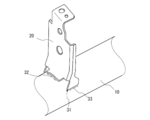
- FIG. 2 is an enlarged view showing the vicinity of a member to be welded in
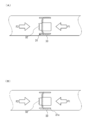
- FIG. 3A is a plan view showing the vicinity of the parts to be welded in FIG. 2 in the welding method according to the embodiment of the present invention
- FIG. 3B shows the proportionality of FIG. 3A. It is a top view.
- the welding apparatus 100 welds and joins a steering member base material 10 (corresponding to a first member) and a component 20 (corresponding to a second member). To do.
- the welding apparatus 100 performs welding for temporarily fixing the component 20 to the steering member base material 10 at the contact portion between the component 20 and the steering member base material 10 to temporarily fix the welding position 31 (see the black circle in FIG. 2.
- the main welding is performed at a position where the part 20 and the steering member base material 10 do not overlap with the temporarily fixed welding position 31, and the main welding positions 32 and 33 (see the two-dot chain line in FIG. 2; see FIGS. 3 to 7). The same applies to the above.
- the component 20 is gripped by the hand robot 110 (corresponding to the gripping portion) and positioned at a position where it is joined to the steering member base material 10.
- Joining to the steering member base material 10 is performed by a welding robot 120 (corresponding to a welded portion).
- the hand robot 110 and the welding robot 120 are multi-axis robots that perform predetermined operations based on previously taught data.
- the steering member base material 10 is supported by support jigs 181 and 182. In this embodiment, items for welding the steering member will be described. However, the present invention is not limited to the steering member. Details will be described below.
- the hand robot 110 has a hand 111 attached to its arm tip.
- the hand robot 110 grips a component in a predetermined direction by the hand 111 and positions the gripped component at a taught position with respect to the steering member base material 10.
- the parts are placed on the parts table 170, and the hand robot 110 grips the parts from the parts table 170 and positions them at a predetermined position on the steering member base material 10.
- the parts are carried into the parts table 170 by another robot (not shown) or a conveyor. Further, instead of the parts table 170, the hand robot 110 may grip the parts flowing by the transport conveyor.
- a first camera 140 that captures the direction of the tip of the hand 111 is attached.
- the first camera 140 is used for capturing the part and grasping the direction and size when the hand 111 takes out the part.
- the second camera 150 is installed within the work range of this process.
- the second camera 150 is used for confirming in what direction the component gripped by the hand 111 is gripped.
- the hand robot 110 operates to hold the component from the component table 170 and then hold the component toward the second camera 150.
- the second camera 150 captures the part gripped by the hand 111, and it is possible to confirm in what direction and position the part is gripped by the hand 111 by image processing.
- the hand robot 110 corrects the orientation of the component so that the component can be positioned on the steering member base material 10 from the orientation and position of the component confirmed by the second camera 150.
- the steering member base material 10 can be positioned at the component position taught with respect to the steering member base material 10. Since the operation of correcting the orientation of the component held by the hand 111 is a general operation of a hand robot, description thereof is omitted.
- the welding robot 120 has a welding torch 121 attached to the arm tip.
- the tip of the welding torch 121 is positioned at a position where the part can be welded with reference to the position of the part positioned on the steering member base material 10.
- the tip position of the welding torch 121 is also corrected.
- the welding robot 120 performs welding using the welding torch 121.
- welding may be performed by a laser injection device.
- a third camera 160 is attached in the vicinity of the root portion of the welding torch 121.
- the third camera 160 photographs the part positioned by the hand 111. Then, the position (and / or inclination) of the component is measured from the captured image. Therefore, the third camera 160 has a function of measuring the size of an object and the distance between objects in a captured image (referred to as an intra-image distance measurement function).
- an image distance measurement function for example, an object (reference scale) used as a reference for determining a distance in an image is photographed in advance, and the correspondence between the actual size of the reference scale and the size in the image is obtained. Keep it.
- Such an intra-image distance measuring function may be a well-known one and is not particularly limited.
- the third camera 160 may have a distance measuring function for measuring the distance from the current position of the third camera 160 to the photographed object.
- a distance measuring function for measuring the distance from the current position of the third camera 160 to the photographed object.
- the distance measuring function may be a well-known one and is not particularly limited. By using such a distance measuring function and an in-image distance measuring function, the part position measured by the third camera 160 can be calculated as the position in the operation coordinate system of the welding robot 120.
- control unit 130 performs image processing in distance measurement within an image, distance measurement performed as necessary, and calculation processing thereof.
- the supporting jigs 181 and 182 support the steering member base material 10 so as to freely rotate around the longitudinal direction while holding both ends of the steering member base material 10 so as not to move in the longitudinal direction.
- the support jigs 181 and 182 include clampers 191 and 192 that clamp the end portions of the steering member base material 10, respectively. Both ends of the steering member base material 10 are clamped by the clampers 191 and 192, and the steering member base material 10 is restrained from moving in the longitudinal direction.
- one support jig 181 is provided with a servomotor with an encoder (not shown) for rotating the clamper 191.
- the motor is equipped with a brake so that it will not rotate inadvertently except during motor operation.
- a rotation angle (amount of rotation) is obtained by feedback from the encoder.
- the clamper 192 of the other support jig 182 is rotatable.
- the steering member base material 10 When welding the bracket to the steering member base material 10, the steering member base material 10 is rotated, and the parts are positioned at the joining position by the hand robot 110 in a specific position, and are welded by the welding robot 120. Therefore, the steering member base material 10 and the side bracket that is first joined to the steering member base material 10 are provided with base material reference points that allow the rotational position of the steering member base material 10 to be known.
- the base material reference point may be a screw hole, a notch, or other mark shape or mark itself.
- the steering member base material 10 is a pipe-like member and is usually a steel pipe. As described above, in the process of joining the components to the steering member base material 10, the side brackets are first attached to both ends of the steering member base material 10, and thereafter, the clampers 191 and 192 hold and rotate the side brackets. Thus, the steering member base material 10 is rotated to the rotation position of the component to be attached next, and the component is carried to a predetermined position by the hand robot 110.
- the control unit 130 has a configuration such as a CPU, a memory, and an input / output interface. With the configuration, the control unit 130 controls the operation of the hand robot 110 and the welding robot 120 and the rotational position of the steering member base material 10 by the support jigs 181 and 182. Control is performed. In addition, the control unit 130 captures the first camera 140, corrects the position of the part gripped by the hand 111 from the image captured by the second camera 150, and sets the distance between objects from the image captured by the third camera 160. It also controls image processing for calculation.
- the control unit 130 may be configured by a single device and may control the support jigs 181 and 182, the hand robot 110, the welding robot 120, the first camera 140, the second camera 150, and the third camera 160. In addition, a device that performs control for each of the above configurations may be provided to perform data communication to control the welding operation.
- the hand robot 110 is previously taught an operation of recognizing and holding a part to be welded to the steering member base material 10 on the part table 170 and recognizing and correcting the position and orientation of the part 20 photographed by the second camera 150. ing. The hand robot 110 is also taught to grip the part 20 and position it at a predetermined position and receive a signal from the welding robot 120 to pick up the next part. This operation is repeated until there are no parts to be welded to the steering member base material 10.
- teaching data is programmed so that the welding torch 121 is moved to perform temporary welding or main welding at a predetermined position.
- the hand robot 110 positions the component 20 at the position taught by the control unit 130. And the welding torch 121 of the welding robot 120 approaches the taught part in the contact part of the steering member base material 10 and the component 20, and performs temporary fixing welding.
- a temporary fixing welding location 31 as shown in FIG. 2 is formed at the contact portion between the steering member base material 10 and the component 20.
- the steering member base material 10 and the component 20 are temporarily fixed and positioned by the temporary fixing weld location 31 until the main welding is performed. Therefore, the hand robot 110 can release the grip of the component 20 after the temporary fixing welding. Therefore, the hand robot 110 can perform operations such as picking up the next part while the welding robot 120 is performing the main welding, and the total amount of time until all the parts are welded to the steering member base material 10. As a result, the welding work time can be shortened.
- Temporary welding can be used as positioning welding because the welding time is shorter than that of main welding and the thermal distortion of the welded part is small. Note that the position of the temporarily welded portion, the weld bead, and the like may be confirmed by the third camera 160.
- the welding torch 121 of the welding robot 120 forms the main welding locations 32 and 33 at the contact portion between the steering member base material 10 and the component 20 based on the teaching data for the main welding.
- two main welding points are formed, but the number of main welding points is not limited to two and may be more than two or one.
- the temporary welding location and the main welding location are numbered according to the welding order (31 ⁇ 32 ⁇ 33 in FIG. 2), and the main welding location 33 is formed after the main welding location 32 is formed. However, it is not limited to this.
- the main welding points 32 and 33 are formed by the control unit 130 and the welding robot 120 so as not to overlap the already formed temporary fixing welding point 31 at the contact portion between the steering member base material 10 and the part. This is because, if the main welding location is overlapped with the temporary welding location, the weld bead at the temporary welding location will be re-melted, thereby making it impossible to position the component 20 on the steering member base material 10. .
- the main welding points 32 and 33 so as not to overlap with the temporary fixing welding point 31, the positioning function of the component 20 with respect to the steering member base material 10 is maintained, a jig for the component 20 is not used, After the temporary welding, the gripping by the hand robot 110 can be released and the welding operation can be performed.
- two or more main welding locations are formed along the direction of the external forces F1 and F2 acting on the component 20 (main welding locations 32 and 33).
- the temporary fixing weld location 31 is formed between the main weld location 32 and the main weld location 33.
- the directions of the external forces F1 and F2 substantially coincide with the longitudinal direction of the steering member base material 10.
- the temporary fixing weld location 31 should just be arrange
- the temporary fixing welded portion 31 is formed so as to be sandwiched between the main welded portions 32 and 33. Even when the external force F1 is loaded in 3 (A), the first welding location 33 receives the input first. Further, even when the external force F2 is applied, the external force F2 is applied to the main welding location 32, and the external force is not initially applied to the temporary welding location 31 where the joining force is relatively weak. Therefore, it is possible to prevent a situation in which breakage occurs from a temporarily welded spot having a relatively weak joining force and breaks to a main weld spot in a chained manner, thereby sufficiently countering external force.
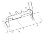
- FIG. 4 is a perspective view showing a case where the welding method according to the present embodiment is used for a part 20a (bracket airbag) different from the part 20 of FIG.
- the position, size, and number of temporary fixing welds are set in consideration of the fact that the part 20 can be temporarily positioned on the steering member base material 10, cracks due to hardening, and the location of the main welds are secured. Is done.
- one temporary fixing welding point 31 is provided.
- the main welding point 32 and the main welding are performed in the longitudinal direction of the steering member base material 10 by the control unit 130 and the welding robot 120.
- Temporary welding locations 31a may be formed between the locations 34
- temporary welding locations 31b may be formed between the main welding locations 33 and the main welding locations 34.
- the part can be positioned by adjusting the bead thickness or length, but the positioning function can be further enhanced by providing two or more locations.
- the positional relationship in the case where two temporary fixing welds are provided can be made symmetrical (180 ° positional relationship) when the contact portion between the steering member base material 10 and the component 20 is viewed in plan.
- the hand robot 110 grips the component 20 and positions it with respect to the steering member base material 10. Then, welding for temporarily fixing the component 20 to the steering member base material 10 is performed at a contact portion between the steering member base material 10 and the component 20 while the component 20 is held, thereby forming a temporary fixing weld location 31. Then, the gripping of the component 20 by the hand robot 110 is released. Then, the main welding is performed at a location other than the temporary welding location 31 at the contact location between the component 20 and the steering member base material 10 to form the main welding locations 32 and 33.
- the temporarily welded portion 31 is not remelted, and the positioning of the component 20 with respect to the steering member base material 10 is maintained by the temporarily welded portion 31. Therefore, the component 20 can be positioned on the steering member base material 10 without temporarily holding the component 20 by the hand robot 110 after the temporary fixing welding, and the hand robot 110 can perform another operation after the temporary fixing welding.
- Temporary fastening welding takes less time than main welding, so that it is possible to cause the hand robot 110 to perform another work after temporary fastening welding, so that the work of welding other parts to the steering member base material 10 can be performed faster. Thus, the operation of manufacturing the steering member can be performed quickly.
- the component 20 is held to the steering member base material 10 with a sufficient joining force until the main welding is performed. It is possible to sufficiently prevent a situation such as dropping from 10.
- main welding locations 32 and 33 are formed along the direction of the external forces F1 and F2 acting on the component 20 (the circumferential direction of the steering member base material 10 in this embodiment) (main welding locations 32 and 33).
- the temporary fixing weld location 31 is formed between the main weld location 32 and the main weld location 33.
- the external force is applied from the main welding location, and the external force is prevented from being first applied to the temporarily welded location. Therefore, it is possible to prevent a situation in which a temporarily welded part that tends to have a weaker bonding force than a main welded part is broken and chained to the main welded part, and the parts are fixed by temporary welding instead of a jig. Even when doing so, the strength of the welded part can be made sufficient. Further, by positioning the audio bracket or the like on the hand robot 110, the positioning operation can be quickly performed with stable accuracy.
- the welding apparatus 100 welds a component 20 corresponding to a second member such as a side bracket, a bracket airbag, an audio bracket, a bracket impact, and an instrument stay to the steering member base material 10 corresponding to the first member. Can be used for etc.
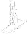
- FIGS. 5 to 7 are perspective views showing the welding method according to the present invention applied to parts different from those shown in FIGS. Note that the welding sequence is performed according to the sequence of the symbols as in FIGS.
- the present invention is not limited to this. Since the audio brackets are provided in pairs, a similar welding method may be used for the other audio bracket (component 20b) as shown in FIG.
- the temporary stay welded portion 31 is formed by the same welding method for the instrument stay (component 20c) shown in FIG. 6 and the bracket impact (component 20d) shown in FIG. , 33 (in addition to FIG. 7, the main welding point 34) may be formed.
- the embodiment has been described in which a plurality of parts such as an audio bracket and an instrument stay are welded to the steering member base material, the present invention is not limited to this.
- the welding method or the welding apparatus according to the present invention can be applied. That is, in a mass production line or the like, when welding for temporarily fixing a welded member to a welded member in one welded part is completed, the hand robot can be used for welding other welded parts, and the welding operation can be performed quickly.
- the embodiment has been described in which the component 20 is gripped by the hand robot 110 and the steering member base material 10 is supported by the support jigs 181 and 182, but the present invention is not limited thereto.
- the support jig used for the steering member base material 10 may be eliminated by gripping not only the component 20 but also the steering member base material 10 by a robot such as the hand robot 110.
- the present invention is not limited to this.
- the component 20 may be temporarily fixed by being positioned by an operator.
- Steering member base material (first member), 100 welding equipment, 110 hand robot (gripping part), 111 hands, 20 parts (second member, audio bracket), 20a parts (bracket airbag), 20b parts (the other audio bracket), 20c parts (instrument), 20d parts (bracket impact), 120 welding robot (welding part), 121 welding torch, 130 control unit, 31, 31a, 31b, 31x 32, 33, 34 welding locations, 140 the first camera, 150 Second camera, 160 Third camera, 170 parts table, 181 and 182 support jigs, 191, 192 Clamper, F1, F2 External force.
Landscapes
- Engineering & Computer Science (AREA)
- Mechanical Engineering (AREA)
- Physics & Mathematics (AREA)
- Optics & Photonics (AREA)
- Plasma & Fusion (AREA)
- Robotics (AREA)
- Manipulator (AREA)
- Arc Welding In General (AREA)
- Laser Beam Processing (AREA)
Abstract
L'invention porte sur un procédé de soudage pour un organe de direction, dans lequel procédé un matériau de base d'organe de direction (10) et un élément (20) sont réunis par soudage. L'élément est saisi par une main de robot (110), et positionné relativement au matériau de base d'organe de direction, provisoirement ancré par réalisation d'un soudage de pointage de l'élément au niveau d'un site de contact entre l'élément et le matériau de base d'organe de direction pendant que l'élément est encore saisi, et un emplacement de soudage de pointage (31) est formé. Un soudage principal est effectué au niveau du site de contact ailleurs qu'aux emplacements de soudage de pointage, et des emplacements de soudage principaux (32, 33) sont formés. Les emplacements de soudage principaux sont formés le long d'une direction de force agissant sur un second organe, et les emplacements de soudage de pointage sont formés entre chacun des emplacements de soudage principaux. Par conséquent, des opérations de soudage sont effectuées rapidement pour l'organe de direction, et analogue, à l'aide de la main de robot.
Priority Applications (1)
| Application Number | Priority Date | Filing Date | Title |
|---|---|---|---|
| JP2015523982A JP6043872B2 (ja) | 2013-06-24 | 2014-06-13 | 溶接部品、溶接方法及び溶接装置 |
Applications Claiming Priority (2)
| Application Number | Priority Date | Filing Date | Title |
|---|---|---|---|
| JP2013131250 | 2013-06-24 | ||
| JP2013-131250 | 2013-06-24 |
Publications (1)
| Publication Number | Publication Date |
|---|---|
| WO2014208372A1 true WO2014208372A1 (fr) | 2014-12-31 |
Family
ID=52141715
Family Applications (1)
| Application Number | Title | Priority Date | Filing Date |
|---|---|---|---|
| PCT/JP2014/065805 Ceased WO2014208372A1 (fr) | 2013-06-24 | 2014-06-13 | Procédé de soudage et dispositif de soudage |
Country Status (2)
| Country | Link |
|---|---|
| JP (1) | JP6043872B2 (fr) |
| WO (1) | WO2014208372A1 (fr) |
Cited By (4)
| Publication number | Priority date | Publication date | Assignee | Title |
|---|---|---|---|---|
| JP2017019053A (ja) * | 2015-07-10 | 2017-01-26 | トヨタ車体株式会社 | ロボット接合システム |
| CN106425202A (zh) * | 2016-11-15 | 2017-02-22 | 合肥星服信息科技有限责任公司 | 一种双工位智能焊接机器人 |
| CN107186318A (zh) * | 2017-06-19 | 2017-09-22 | 中车长春轨道客车股份有限公司 | 一种转向架数字化焊接规范监测方法 |
| CN109094678A (zh) * | 2018-08-22 | 2018-12-28 | 南京理工大学 | 一种通用型无人驾驶机器人 |
Citations (6)
| Publication number | Priority date | Publication date | Assignee | Title |
|---|---|---|---|---|
| JPS61241264A (ja) * | 1985-04-19 | 1986-10-27 | Nissan Motor Co Ltd | 自動車のステアリング支持構造 |
| US4760232A (en) * | 1986-10-21 | 1988-07-26 | Mec-Fab Inc. | Method of cladding a steel cylindrical core |
| JPH058088A (ja) * | 1991-06-28 | 1993-01-19 | Nkk Corp | 金属ストリツプの接続方法及び位置決め固定装置 |
| JP2007069333A (ja) * | 2005-09-08 | 2007-03-22 | Toyota Motor Corp | ロボットハンド、ロボットおよび溶接方法 |
| JP2008161911A (ja) * | 2006-12-28 | 2008-07-17 | Sumitomo Metal Ind Ltd | 衝撃吸収部材及びその製造方法 |
| JP2008178905A (ja) * | 2007-01-26 | 2008-08-07 | Nippon Steel Corp | 鋼板で構成された構造体のレーザー溶接方法 |
-
2014
- 2014-06-13 WO PCT/JP2014/065805 patent/WO2014208372A1/fr not_active Ceased
- 2014-06-13 JP JP2015523982A patent/JP6043872B2/ja not_active Expired - Fee Related
Patent Citations (6)
| Publication number | Priority date | Publication date | Assignee | Title |
|---|---|---|---|---|
| JPS61241264A (ja) * | 1985-04-19 | 1986-10-27 | Nissan Motor Co Ltd | 自動車のステアリング支持構造 |
| US4760232A (en) * | 1986-10-21 | 1988-07-26 | Mec-Fab Inc. | Method of cladding a steel cylindrical core |
| JPH058088A (ja) * | 1991-06-28 | 1993-01-19 | Nkk Corp | 金属ストリツプの接続方法及び位置決め固定装置 |
| JP2007069333A (ja) * | 2005-09-08 | 2007-03-22 | Toyota Motor Corp | ロボットハンド、ロボットおよび溶接方法 |
| JP2008161911A (ja) * | 2006-12-28 | 2008-07-17 | Sumitomo Metal Ind Ltd | 衝撃吸収部材及びその製造方法 |
| JP2008178905A (ja) * | 2007-01-26 | 2008-08-07 | Nippon Steel Corp | 鋼板で構成された構造体のレーザー溶接方法 |
Cited By (6)
| Publication number | Priority date | Publication date | Assignee | Title |
|---|---|---|---|---|
| JP2017019053A (ja) * | 2015-07-10 | 2017-01-26 | トヨタ車体株式会社 | ロボット接合システム |
| CN106425202A (zh) * | 2016-11-15 | 2017-02-22 | 合肥星服信息科技有限责任公司 | 一种双工位智能焊接机器人 |
| CN107186318A (zh) * | 2017-06-19 | 2017-09-22 | 中车长春轨道客车股份有限公司 | 一种转向架数字化焊接规范监测方法 |
| CN107186318B (zh) * | 2017-06-19 | 2018-07-03 | 中车长春轨道客车股份有限公司 | 一种转向架数字化焊接规范监测方法 |
| CN109094678A (zh) * | 2018-08-22 | 2018-12-28 | 南京理工大学 | 一种通用型无人驾驶机器人 |
| CN109094678B (zh) * | 2018-08-22 | 2020-10-30 | 南京理工大学 | 一种通用型无人驾驶机器人 |
Also Published As
| Publication number | Publication date |
|---|---|
| JPWO2014208372A1 (ja) | 2017-02-23 |
| JP6043872B2 (ja) | 2016-12-14 |
Similar Documents
| Publication | Publication Date | Title |
|---|---|---|
| CN103889650B (zh) | 接合体的制造方法及其制造装置 | |
| JP3665353B2 (ja) | ロボットの教示位置データの3次元位置補正量取得方法及びロボットシステム | |
| JP2015223604A (ja) | 接合部品の製造方法、および接合部品の製造装置 | |
| JP6550985B2 (ja) | ロボット接合システム | |
| JP6043872B2 (ja) | 溶接部品、溶接方法及び溶接装置 | |
| CN104551291A (zh) | 自动焊接系统 | |
| JP6153316B2 (ja) | ロボットシステム及びロボットシステムの制御方法 | |
| CN109996653A (zh) | 作业位置校正方法及作业机器人 | |
| JP6314506B2 (ja) | 車両部品の製造装置及び製造方法 | |
| KR102137615B1 (ko) | 검사용 로봇 그리퍼 및 그 제어 방법 | |
| JP2016022563A (ja) | 接合部品の製造装置、および接合部品の製造方法 | |
| JP2015208746A (ja) | 接合部品の製造装置およびその製造方法 | |
| JP2015226966A (ja) | 溶接部品の製造方法 | |
| JP5002483B2 (ja) | スポット溶接ロボットを使用する溶接システム | |
| JP5157815B2 (ja) | ロボット装置及びロボット装置教示方法 | |
| JP6367702B2 (ja) | 位置決めシステム及び溶接システム | |
| JP2016022562A (ja) | 接合部品の製造装置及び製造方法 | |
| JP5521148B2 (ja) | ロボット装置及びロボット装置の制御方法 | |
| JP2010017750A (ja) | ロボット装置及びワークの組立方法 | |
| JP2016022577A (ja) | 溶接品の製造装置および製造方法 | |
| EP2781297A1 (fr) | Procédé de fabrication de joint et dispositif de fabrication apparenté | |
| JP2016022515A (ja) | 接合状態の検査方法及び検査装置 | |
| JP2015208745A (ja) | 接合部品の製造方法およびその製造装置 | |
| JP2016028835A (ja) | 接合部品の製造装置、および接合部品の製造方法 | |
| JP2015208821A (ja) | 接合部品の製造装置、接合部品の製造方法、および接合部品 |
Legal Events
| Date | Code | Title | Description |
|---|---|---|---|
| 121 | Ep: the epo has been informed by wipo that ep was designated in this application |
Ref document number: 14817899 Country of ref document: EP Kind code of ref document: A1 |
|
| DPE1 | Request for preliminary examination filed after expiration of 19th month from priority date (pct application filed from 20040101) | ||
| ENP | Entry into the national phase |
Ref document number: 2015523982 Country of ref document: JP Kind code of ref document: A |
|
| NENP | Non-entry into the national phase |
Ref country code: DE |
|
| 122 | Ep: pct application non-entry in european phase |
Ref document number: 14817899 Country of ref document: EP Kind code of ref document: A1 |