WO2015001606A1 - 撮像システム - Google Patents
撮像システム Download PDFInfo
- Publication number
- WO2015001606A1 WO2015001606A1 PCT/JP2013/068062 JP2013068062W WO2015001606A1 WO 2015001606 A1 WO2015001606 A1 WO 2015001606A1 JP 2013068062 W JP2013068062 W JP 2013068062W WO 2015001606 A1 WO2015001606 A1 WO 2015001606A1
- Authority
- WO
- WIPO (PCT)
- Prior art keywords
- imaging
- user
- gesture
- imaging area
- detection
- Prior art date
- Legal status (The legal status is an assumption and is not a legal conclusion. Google has not performed a legal analysis and makes no representation as to the accuracy of the status listed.)
- Ceased
Links
Images





Classifications
-
- B—PERFORMING OPERATIONS; TRANSPORTING
- B60—VEHICLES IN GENERAL
- B60K—ARRANGEMENT OR MOUNTING OF PROPULSION UNITS OR OF TRANSMISSIONS IN VEHICLES; ARRANGEMENT OR MOUNTING OF PLURAL DIVERSE PRIME-MOVERS IN VEHICLES; AUXILIARY DRIVES FOR VEHICLES; INSTRUMENTATION OR DASHBOARDS FOR VEHICLES; ARRANGEMENTS IN CONNECTION WITH COOLING, AIR INTAKE, GAS EXHAUST OR FUEL SUPPLY OF PROPULSION UNITS IN VEHICLES
- B60K15/00—Arrangement in connection with fuel supply of combustion engines or other fuel consuming energy converters, e.g. fuel cells; Mounting or construction of fuel tanks
- B60K15/03—Fuel tanks
- B60K15/04—Tank inlets
-
- B—PERFORMING OPERATIONS; TRANSPORTING
- B60—VEHICLES IN GENERAL
- B60K—ARRANGEMENT OR MOUNTING OF PROPULSION UNITS OR OF TRANSMISSIONS IN VEHICLES; ARRANGEMENT OR MOUNTING OF PLURAL DIVERSE PRIME-MOVERS IN VEHICLES; AUXILIARY DRIVES FOR VEHICLES; INSTRUMENTATION OR DASHBOARDS FOR VEHICLES; ARRANGEMENTS IN CONNECTION WITH COOLING, AIR INTAKE, GAS EXHAUST OR FUEL SUPPLY OF PROPULSION UNITS IN VEHICLES
- B60K35/00—Instruments specially adapted for vehicles; Arrangement of instruments in or on vehicles
- B60K35/10—Input arrangements, i.e. from user to vehicle, associated with vehicle functions or specially adapted therefor
-
- G—PHYSICS
- G06—COMPUTING OR CALCULATING; COUNTING
- G06F—ELECTRIC DIGITAL DATA PROCESSING
- G06F3/00—Input arrangements for transferring data to be processed into a form capable of being handled by the computer; Output arrangements for transferring data from processing unit to output unit, e.g. interface arrangements
- G06F3/002—Specific input/output arrangements not covered by G06F3/01 - G06F3/16
- G06F3/005—Input arrangements through a video camera
-
- G—PHYSICS
- G06—COMPUTING OR CALCULATING; COUNTING
- G06F—ELECTRIC DIGITAL DATA PROCESSING
- G06F3/00—Input arrangements for transferring data to be processed into a form capable of being handled by the computer; Output arrangements for transferring data from processing unit to output unit, e.g. interface arrangements
- G06F3/01—Input arrangements or combined input and output arrangements for interaction between user and computer
- G06F3/011—Arrangements for interaction with the human body, e.g. for user immersion in virtual reality
- G06F3/013—Eye tracking input arrangements
-
- G—PHYSICS
- G06—COMPUTING OR CALCULATING; COUNTING
- G06F—ELECTRIC DIGITAL DATA PROCESSING
- G06F3/00—Input arrangements for transferring data to be processed into a form capable of being handled by the computer; Output arrangements for transferring data from processing unit to output unit, e.g. interface arrangements
- G06F3/01—Input arrangements or combined input and output arrangements for interaction between user and computer
- G06F3/017—Gesture based interaction, e.g. based on a set of recognized hand gestures
-
- G—PHYSICS
- G06—COMPUTING OR CALCULATING; COUNTING
- G06V—IMAGE OR VIDEO RECOGNITION OR UNDERSTANDING
- G06V20/00—Scenes; Scene-specific elements
- G06V20/50—Context or environment of the image
- G06V20/59—Context or environment of the image inside of a vehicle, e.g. relating to seat occupancy, driver state or inner lighting conditions
- G06V20/597—Recognising the driver's state or behaviour, e.g. attention or drowsiness
-
- G—PHYSICS
- G06—COMPUTING OR CALCULATING; COUNTING
- G06V—IMAGE OR VIDEO RECOGNITION OR UNDERSTANDING
- G06V40/00—Recognition of biometric, human-related or animal-related patterns in image or video data
- G06V40/10—Human or animal bodies, e.g. vehicle occupants or pedestrians; Body parts, e.g. hands
- G06V40/18—Eye characteristics, e.g. of the iris
- G06V40/19—Sensors therefor
-
- H—ELECTRICITY
- H04—ELECTRIC COMMUNICATION TECHNIQUE
- H04N—PICTORIAL COMMUNICATION, e.g. TELEVISION
- H04N23/00—Cameras or camera modules comprising electronic image sensors; Control thereof
- H04N23/60—Control of cameras or camera modules
- H04N23/61—Control of cameras or camera modules based on recognised objects
- H04N23/611—Control of cameras or camera modules based on recognised objects where the recognised objects include parts of the human body
-
- B—PERFORMING OPERATIONS; TRANSPORTING
- B60—VEHICLES IN GENERAL
- B60K—ARRANGEMENT OR MOUNTING OF PROPULSION UNITS OR OF TRANSMISSIONS IN VEHICLES; ARRANGEMENT OR MOUNTING OF PLURAL DIVERSE PRIME-MOVERS IN VEHICLES; AUXILIARY DRIVES FOR VEHICLES; INSTRUMENTATION OR DASHBOARDS FOR VEHICLES; ARRANGEMENTS IN CONNECTION WITH COOLING, AIR INTAKE, GAS EXHAUST OR FUEL SUPPLY OF PROPULSION UNITS IN VEHICLES
- B60K2360/00—Indexing scheme associated with groups B60K35/00 or B60K37/00 relating to details of instruments or dashboards
- B60K2360/146—Instrument input by gesture
-
- B—PERFORMING OPERATIONS; TRANSPORTING
- B60—VEHICLES IN GENERAL
- B60K—ARRANGEMENT OR MOUNTING OF PROPULSION UNITS OR OF TRANSMISSIONS IN VEHICLES; ARRANGEMENT OR MOUNTING OF PLURAL DIVERSE PRIME-MOVERS IN VEHICLES; AUXILIARY DRIVES FOR VEHICLES; INSTRUMENTATION OR DASHBOARDS FOR VEHICLES; ARRANGEMENTS IN CONNECTION WITH COOLING, AIR INTAKE, GAS EXHAUST OR FUEL SUPPLY OF PROPULSION UNITS IN VEHICLES
- B60K2360/00—Indexing scheme associated with groups B60K35/00 or B60K37/00 relating to details of instruments or dashboards
- B60K2360/146—Instrument input by gesture
- B60K2360/1464—3D-gesture
-
- B—PERFORMING OPERATIONS; TRANSPORTING
- B60—VEHICLES IN GENERAL
- B60K—ARRANGEMENT OR MOUNTING OF PROPULSION UNITS OR OF TRANSMISSIONS IN VEHICLES; ARRANGEMENT OR MOUNTING OF PLURAL DIVERSE PRIME-MOVERS IN VEHICLES; AUXILIARY DRIVES FOR VEHICLES; INSTRUMENTATION OR DASHBOARDS FOR VEHICLES; ARRANGEMENTS IN CONNECTION WITH COOLING, AIR INTAKE, GAS EXHAUST OR FUEL SUPPLY OF PROPULSION UNITS IN VEHICLES
- B60K2360/00—Indexing scheme associated with groups B60K35/00 or B60K37/00 relating to details of instruments or dashboards
- B60K2360/149—Instrument input by detecting viewing direction not otherwise provided for
-
- B—PERFORMING OPERATIONS; TRANSPORTING
- B60—VEHICLES IN GENERAL
- B60K—ARRANGEMENT OR MOUNTING OF PROPULSION UNITS OR OF TRANSMISSIONS IN VEHICLES; ARRANGEMENT OR MOUNTING OF PLURAL DIVERSE PRIME-MOVERS IN VEHICLES; AUXILIARY DRIVES FOR VEHICLES; INSTRUMENTATION OR DASHBOARDS FOR VEHICLES; ARRANGEMENTS IN CONNECTION WITH COOLING, AIR INTAKE, GAS EXHAUST OR FUEL SUPPLY OF PROPULSION UNITS IN VEHICLES
- B60K2360/00—Indexing scheme associated with groups B60K35/00 or B60K37/00 relating to details of instruments or dashboards
- B60K2360/20—Optical features of instruments
- B60K2360/21—Optical features of instruments using cameras
-
- B—PERFORMING OPERATIONS; TRANSPORTING
- B60—VEHICLES IN GENERAL
- B60R—VEHICLES, VEHICLE FITTINGS, OR VEHICLE PARTS, NOT OTHERWISE PROVIDED FOR
- B60R2300/00—Details of viewing arrangements using cameras and displays, specially adapted for use in a vehicle
- B60R2300/80—Details of viewing arrangements using cameras and displays, specially adapted for use in a vehicle characterised by the intended use of the viewing arrangement
- B60R2300/8006—Details of viewing arrangements using cameras and displays, specially adapted for use in a vehicle characterised by the intended use of the viewing arrangement for monitoring and displaying scenes of vehicle interior, e.g. for monitoring passengers or cargo
Definitions
- the present invention relates to the technical field of an imaging system including an imaging device.
- Patent Documents 1 to 4 relating to a technique for imaging a user's face.
- Patent Document 1 describes a technique for recognizing an iris by analyzing eye position data using a camera that captures the entire face and a moving camera that captures an eye portion.
- Japanese Patent Application Laid-Open No. 2004-228561 describes a technique for photographing a face image, determining the size of the face, and zooming to an appropriate angle of view.
- Patent Document 3 describes a technique for changing the menu display of an electronic camera depending on whether or not a face is recognized.
- Patent Document 4 describes a technique for providing a face recognizing unit and a unit for detecting movement in a face area, and when a makeup tool or the like moves, enlarges and displays the periphery of the portion where the movement has occurred. Yes.
- the gaze direction is measured from the eyeball center position obtained from the edge of the glow and the face position by irradiating near infrared rays and using the image of the pupil of the eyeball and the Purkinje image. Techniques and the like are known.
- the virtual image display device of Patent Document 8 includes a viewpoint detection camera that captures the driver's eyes and a gesture detection camera that captures the driver's hand.
- the driver When the driver performs an action of pointing the display virtual image with the fingertip, the image captured by the viewpoint detection camera and the gesture detection camera is subjected to image recognition processing, and the driver's line of sight is identified through detection of the driver's eye position and fingertip position.
- the display of the gaze virtual image on the specified line of sight is controlled based on the display control command.
- Detecting the gaze direction requires image analysis of the user's eyes. For example, it is said that about 70 pixels are required for the diameter of the luminosity in order to detect the line-of-sight direction with accuracy of the order of 1 degree.
- the detection of the gaze direction and the detection of the gesture are common in that the user's imaging result is used, the detection of the gaze direction requires a high-resolution image related to the user's eyes as described above.
- an image of a wider body such as a user's finger is not limited to the face.
- both the resolution and the angle of view that is, the size of the imaging area
- an imaging apparatus having both a resolution and an angle of view is expensive, and high processing capability is required for an image processing circuit for processing high-resolution image data.
- the processing capability of the image processing circuit is proportional to the cost. That is, in order to realize the detection of the line-of-sight direction and the detection of the gesture with a single imaging device, an increase in cost is an unavoidable problem.
- the present invention has been made in view of such a problem, for example, and provides an imaging system capable of realizing gaze direction detection and gesture detection with a single imaging device without increasing costs. This should be at least one of the issues to be solved.
- the imaging system is used for detecting a gesture including a first imaging region used for detecting a user's line of sight and the upper body of the user.
- An imaging means capable of imaging a second imaging area wider than the first imaging area; a detecting means for detecting a trigger action of the user; and the first imaging area based on a detection result of the trigger action.
- a selection means for selecting the second imaging region.
- the imaging method according to claim 7 is used for detection of a gesture including a first imaging region used for detecting a user's line of sight and the upper body of the user.
- An imaging method in an imaging system including an imaging unit capable of imaging a second imaging area wider than the first imaging area, the detection method detecting a trigger action of the user, and the detected A selection step of selecting the first imaging area or the second imaging area based on a trigger operation.
- a computer program according to claim 8 causes a computer apparatus to function as the imaging system according to any one of claims 1 to 6.
- the recording medium according to claim 9 is recorded with the computer program according to claim 8.
- FIG. 1 is a block diagram of an information display system according to an embodiment of the present invention. It is a figure explaining the installation position of an imaging device. It is a figure which illustrates the telephoto side imaging area in telephoto mode. It is a figure which illustrates the wide angle side imaging region in wide angle mode. It is a flowchart of an imaging mode control process. It is a figure which illustrates the condition where the gesture was detected in the telephoto mode. It is a figure explaining the 1st case concerning trigger operation judging. It is a figure explaining the 2nd case which concerns on trigger operation
- Embodiments according to the imaging system of the present invention are wider than the first imaging region used for detecting a first imaging region used for detecting a user's line of sight and a gesture including the upper body of the user.
- the imaging means is configured to be capable of imaging the first imaging area and the second imaging area.
- capturing an imaging area means obtaining an image or video relating to the imaging area.
- the first imaging region is used for detecting the user's line of sight, and is available or suitable for use, for example, an imaging region that includes, for example, a pupil, eyes, the periphery of the eyes, or the upper half of the face as a suitable form. It is.
- the first imaging area may be set as an imaging area in which, for example, the ratio of the user's face or head in the first imaging area is greater than or equal to a predetermined value.
- the second imaging region is used for detection of a gesture including the upper body of the user, and is usable or suitable for use.
- the second imaging region includes a body above the upper body or the chest. It is a wide imaging area.
- the imaging area of the imaging means is not necessarily limited to the first and second imaging areas. Further, the second imaging area may be an imaging area including at least a part of the first imaging area.
- Various known techniques are applied to switching of the imaging area between the first imaging area and the second imaging area having a wider angle of view than the first imaging area, or switching of the imaging mode associated with the imaging area. can do.
- the switching of the imaging area may be realized by, for example, a zoom-in / out switching function provided in the imaging unit.
- a wide angle of view that is, a second angle of view
- a wide conversion lens It may be realized by switching to the imaging region) or enlargement by a tele conversion lens (that is, switching to the first imaging region).
- the switching of the imaging area is performed based on the detection result of the user's trigger operation. That is, the embodiment according to the imaging system is configured such that the selection unit selects the first imaging region or the second imaging region based on the detection result of the trigger operation.
- Trigger operation is an operation premised on that the user performs based on his / her own intention, and is a concept that encompasses all of the operations that can be performed by the user and that can be detected.
- the trigger operation may include a user gesture, a user utterance, an operation of a physical operation means, or the like.
- This trigger operation is ideally associated with one imaging region to be selected from the first imaging region and the second imaging region, but this need not necessarily be the case. Specifically, every time a single trigger operation is detected, the imaging area may be alternately selected from the first imaging area ⁇ the second imaging area ⁇ the first imaging area. .
- Various known methods can be applied to the detection of the trigger operation according to the type of the trigger operation.
- both a wide angle of view and a high resolution are required as described above.
- the resolution is more important than the angle of view in the detection of the line-of-sight direction, and particularly the resolution of the eye image, and the angle of view is more important than the resolution in detecting the gesture. That is, in practice, both the angle of view and the resolution are not required at the same time.
- the resolution of the eye portion in the second imaging region may be low enough that it is not necessarily sufficient for detecting the line-of-sight direction.
- the resolution of the eye portion in the first imaging area can be relatively improved by enlarging the imaging area and relatively narrowing the angle of view as compared with the second imaging area.
- the embodiment relating to the imaging system it is possible to reduce the resolution of the imaging means that affects the cost while ensuring the detection accuracy of the line-of-sight direction based on such a principle. That is, the gaze direction detection and the gesture detection can be realized by a single imaging device without causing an increase in cost.
- the imaging system includes control means for controlling the imaging means so that the selected first or second imaging region is imaged (claim 2). .
- the imaging region is switched according to the trigger operation that prompts switching from the first (or second) imaging region to the second (or first) imaging region, and the first (or second) imaging is performed.
- the first (or second) imaging area can be accurately imaged.
- the trigger operation includes at least one of a gesture, utterance, and an input operation via a predetermined input means (claim 3).
- the second imaging area includes at least a part of the first imaging area, and the first imaging area when the first imaging area is selected. Is higher than the resolution of the first imaging area when the second imaging area is selected (Claim 4).
- the switching of the imaging area to the second imaging area can be realized only by switching the angle of view of the imaging means, for example.
- the resolution (for example, the number of pixels) of the imaging element of the imaging means can be a fixed value.
- the selection unit selects the first imaging area when the user's gesture is not detected in the state where the second imaging area is selected ( Claim 5).
- the second imaging region only when a gesture is detected, and it is possible to suitably ensure an opportunity to detect the line-of-sight direction.
- a special trigger operation by the user is not required, which is beneficial to the user.
- the selection unit detects a part of the user's face being shielded as the trigger operation in a state where the first imaging region is selected.
- the second imaging region is selected (Claim 6).
- the gesture When using a gesture as a trigger operation, the gesture needs to be detectable in the first imaging area having a narrow angle of view.
- the first imaging region preferably includes a face
- the gesture with such a restriction is made, there is a high possibility that a part of the user's face is shielded.
- the embodiment according to the imaging method of the present invention is wider than the first imaging area used for detecting a first imaging area used for detecting a user's line of sight and a gesture including the upper body of the user.
- An imaging method in an imaging system including an imaging unit capable of imaging a second imaging area, the detection step detecting a trigger operation of the user, and the first imaging area based on the detected trigger operation Or a selection step of selecting the second imaging region (Claim 7).
- the detection step and the selection step that realize the same operation as the detection unit and selection unit of the embodiment related to the imaging system, as in the embodiment related to the imaging system, the cost and It is possible to realize gaze direction detection and gesture detection with a single imaging apparatus without causing an increase in the size of the apparatus.
- the embodiment according to the computer program of the present invention causes the computer device to function as the imaging system according to any one of the above (claim 8).
- the computer program is read into the computer system from a solid-state storage device such as a ROM, CD-ROM, DVD-ROM, hard disk or other storage medium storing the computer program, or a USB (Universal Serial Bus) memory.
- a solid-state storage device such as a ROM, CD-ROM, DVD-ROM, hard disk or other storage medium storing the computer program, or a USB (Universal Serial Bus) memory.
- a USB Universal Serial Bus
- the embodiment of the computer program of the present invention can also adopt various aspects.
- the embodiment according to the recording medium of the present invention records the embodiment according to the computer program (claim 9).
- the computer program of the present invention recorded by being attached to or connected to a computer system, or by being inserted into an appropriate reader provided in or connected to the computer system.
- the embodiment according to the present invention can be read and executed by a computer system, and the embodiment according to the imaging system of the present invention described above can be realized relatively easily.
- FIG. 1 is a block diagram of the information display system 10.
- an information display system 10 is a device that is mounted on a vehicle (not shown) and provides various types of information to a user 1 who is a driver of the vehicle.
- the information display system 10 includes a control device 100, a display DP, and an imaging device CM.
- the display DP and the imaging device CM are electrically connected to the control device 100, respectively.
- the information display system 10 is configured as a part of a car navigation system (not shown). Therefore, the information display system 10 can provide the user 1 with various types of information such as vehicle position information, map information, peripheral facility information, and road information.
- the application of the imaging system according to the present invention is not limited to the field of car navigation.
- the present invention can be applied to information display in a personal computer device.
- control device 100 and the imaging device CM constitute an example of the “imaging system” according to the present invention.
- the display DP is a display device fixed in a state of being suspended from the roof portion in front of the windshield in front of the driver's seat of the vehicle.
- the display DP has a display screen used for visual recognition of the user 1.
- the display content of the display DP is configured to be controlled by the control device 100 electrically connected to the display DP.
- the imaging device CM is a digital video camera as an example of the “imaging means” according to the present invention, which is fixed so that the user 1 can be imaged in the vicinity of the steering column located on the back side of the vehicle handle HD.
- the operation of the imaging device CM is controlled by the control device 100 that is electrically connected to the imaging device CM.
- the imaging device CM is equipped with an image sensor (for example, including a CCD or a CMOS sensor) having a certain resolution (that is, the number of pixels), and the imaging area includes a telephoto side imaging area and a wide angle side imaging area. It is possible to switch between them.
- the imaging area of the imaging device CM has a one-to-one correspondence with the imaging mode selected by the imaging mode selection unit 130 described later. That is, when the wide-angle mode is selected as the imaging mode, the imaging area of the imaging device CM is the wide-angle-side imaging area optimized for detecting the gesture of the user 1 (that is, the “second imaging” according to the present invention). An example of “region”.
- control is performed for each of the telephoto-side imaging areas optimized for detecting the user's line-of-sight direction (that is, an example of the “first imaging area” according to the present invention). .
- switching of the imaging area in the imaging device CM is realized by a zoom-in / out function of the imaging device CM. That is, when a zoom-in control signal is supplied from an imaging control unit 140 described later, the drive control circuit inside the imaging device CM drives the lens motor, a part of the first imaging area is enlarged, and the imaging area is captured on the telephoto side. Switch to the area. Conversely, when a zoom-out control signal is supplied from the imaging control unit 140, the drive control circuit inside the imaging apparatus CM drives the lens motor, the imaging area is enlarged, and the imaging area is wide-angle-side imaging area. Can be switched to.
- a tele-conversion lens can realize a function equivalent to zoom-in, and a wide conversion lens can realize a function equivalent to zoom-out. be able to.
- a lens attaching / detaching mechanism may be provided in the imaging device CM or in the periphery thereof.
- FIG. 2 is a diagram illustrating the installation position of the imaging device CM.
- (a) and (b) are images of the face of the user 1 in a certain sitting posture taken from different directions. Specifically, (a) is a view taken from the front, and (b) is a view taken from below than (a).
- the imaging device CM is installed in the vicinity of the steering column located on the back side of the vehicle handle HD so that the user 1 can be imaged from the direction corresponding to FIG. Yes. Also, when using gaze detection for personal computer operation, the imaging device is preferably installed at a position where the periphery of the eyes of the user 1 can be photographed from the front of the user 1 and obliquely below.
- the control device 100 is a computer device that controls the operation of the information display system 10.
- the control device 100 includes a control unit 110, an operation detection unit 120, an imaging mode selection unit 130, an imaging control unit 140, a line-of-sight direction detection unit 150, a gesture detection unit 160, and a display control unit 170.
- the control unit 110 is an arithmetic processing device including a CPU (Central processing Unit) ROM (Read Only Memory), a RAM (Random Access Memory), and the like.
- the ROM of the control unit 110 stores control programs related to various controls executed by the control device 110. Each part of the control device 100 is configured such that its operation is controlled by this control program.
- This control program includes a control program related to an imaging mode control process to be described later.
- control program related to the imaging mode control processing is an example of the “computer program” according to the present invention.
- the ROM is an example of the “recording medium” according to the present invention.
- a control program related to the imaging mode control processing is provided in the control unit 110 in advance, but this control program is provided in the RAM or other volatile memory that can be provided in the control device 100. May be written in the volatile storage device. In this case, update and maintenance of the control program can be performed relatively easily. It is also possible to take measures such as distributing the control program over a network or distributing a recording medium on which the control program is recorded.
- the operation detection unit 120 is an example of the “detection unit” according to the present invention configured to be able to detect the trigger operation of the user 1 that prompts switching of the imaging mode of the imaging device CM.
- the operation detection unit 120 includes a voice detection unit 121 and a switch state detection unit 122.
- the voice detection unit 121 is electrically connected to a microphone that collects the voice of the user 1, and can analyze the voice signal related to the voice and specify the utterance content of the user 1.
- a voice analysis method in a known voice input device can be used for voice analysis in the voice detection unit 121.
- the switch state detection unit 122 is electrically connected to an operation switch that can be operated by the user 1, and can identify the operation state of the operation switch.
- the operation switch may be a push switch, a toggle switch, or a lever switch.
- the operation switch in the present embodiment includes an on switch corresponding to the on operation and an off switch corresponding to the off operation. The on operation and the off operation will be described later.
- the imaging mode selection unit 130 is an example of a “selection unit” according to the present invention that selects an imaging mode of the imaging device CM.
- the imaging control unit 140 is a control unit that controls the operation of the imaging apparatus CM.
- the imaging control unit 140 controls the operation of the imaging device CM by supplying a control signal to a control circuit built in the imaging device CM. For example, when one imaging mode is selected by the imaging mode selection unit 130, the imaging control unit 140 supplies a view angle control signal so that an imaging region corresponding to the selected imaging mode is obtained. Then, after the angle of view is adjusted according to the supplied control signal, an imaging control signal is supplied so that imaging is started.
- the gaze direction detection unit 150 is an image processing circuit configured to be able to detect the gaze direction of the user 1 from the imaging result of the imaging device CM temporarily stored in the RAM of the control unit 110.
- the imaging mode is controlled to the telephoto mode when detection of the gaze direction is required or when detection of the gesture is not required. Since the installation position of the imaging device CM is fixed, after the initial setting process according to the seating position and posture of the user 1 (vehicle driver in the present embodiment) is performed, imaging is performed in the telephoto side imaging region.
- the direction of the line of sight of the user 1 can be detected from the image of the eyes of the user 1 (especially around the pupil) using a known algorithm or arithmetic expression. Note that the detection of the line-of-sight direction itself has a low correlation with the present invention, and thus a detailed description thereof will be omitted.
- the gesture detection unit 160 is a processing circuit configured to be able to detect the gesture of the user 1 from the imaging result of the imaging device CM temporarily stored in the RAM of the control unit 110.
- Various known image analysis methods such as a face detection method and a pattern recognition method can be applied to the gesture detection in the gesture detection unit 160.
- the display control unit 170 is a control circuit that determines information to be displayed on the display DP based on positioning information obtained from GPS (Global Positioning System) or the like, and displays the information on the display screen through the control of the display DP. is there.
- the display control unit 170 is configured to control the screen configuration of the display screen including the type and layout of information to be displayed according to the state of the user 1.
- “the state of the user 1” means the gaze direction of the user 1 detected by the gaze direction detection unit 150, the gesture of the user 1 detected by the gesture detection unit 160, and the like.
- the information display system 10 is a kind of car navigation system, and display information based on map information, facility information, road information, destination information set in advance, set route information, position information, and the like. Is determined and displayed on the display DP.
- the current position and the traveling direction are acquired based on a GPS signal or the like, and the current position and the traveling direction are displayed as position information on the map from separately acquired map information.
- a near-future travel route is predicted based on the set route information and any search condition is set at that time, information on facilities and the like that match the search condition is displayed on this near-future travel route. Is done. For example, if “restaurant” is set as the search condition, information on the restaurant on the travel route of the vehicle is retrieved from the facility information and displayed on the display screen in a form superimposed on the map information.
- the information display system 10 can display optimal information according to the line-of-sight direction and gesture of the user 1 based on the function as such a car navigation system.
- the line-of-sight direction of the user 1 corresponds to a specific position of the display DP
- information desired by the user 1 can be displayed at that position.
- the user 1 points to specific information displayed on the display DP by a gesture such as a pointing action
- the corresponding information is enlarged or more detailed information regarding the corresponding information is displayed. be able to.
- the line-of-sight direction and the gesture of the user 1 are used for determining the information display content.
- the detection of the line-of-sight direction requires an appropriate resolution for the face of the user 1, particularly the image around the eyes, and the detection of a gesture includes a relatively wide imaging area including the upper body of the user 1. is necessary.
- the imaging device CM has a wide field angle and high resolution in order to satisfy both, the cost increases.
- the imaging unit control process is executed by the control unit 110.
- the imaging mode control process is a process for accurately controlling the imaging area of the imaging apparatus CM.
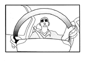
- FIG. 3 is a diagram illustrating the telephoto side imaging region
- FIG. 4 is a diagram illustrating the wide angle side imaging region.
- an image obtained by capturing the user 1 in the telephoto side imaging region is an image suitable for detecting the user 1's line-of-sight direction.
- the ratio of the face in the telephoto side imaging region (that is, the predetermined ratio) is the distance between the imaging device CM and the user 1, the angle of view in the telephoto mode, and the optical resolution of the image sensor (for example, the number of pixels). It changes according to the three elements. The combination of these three elements may be freely determined as long as the resolution necessary for the detection of the line-of-sight direction is obtained in the peripheral portion of the user's eye.
- the wide-angle mode is selected as the imaging mode of the imaging apparatus CM and the imaging area is controlled to the wide-angle imaging area
- the upper body of the user 1 is included in the imaging area. That is, as the angle of view of the imaging device CM increases, the imaging area becomes wider than the telephoto side imaging area. Therefore, an image obtained by capturing the user 1 in the wide-angle imaging region is an image suitable for detecting the user 1 gesture.
- the wide-angle side imaging area is an imaging area including all of the telephoto side imaging area.
- the wide-angle imaging area is obtained by changing the angle of view from the telephoto imaging area. Therefore, in the wide-angle side imaging region, even if the optical resolution of the image sensor of the imaging device CM is a fixed value, the resolution of the peripheral portion of the user's eyeball necessary for detecting the user's 1 gaze direction is the telephoto side. Low compared to the imaging area.
- FIG. 5 is a flowchart of the imaging mode control process.
- the imaging mode control process is a process that is repeatedly executed at a predetermined cycle.
- the control part 110 performs a trigger operation
- the trigger action determination process is a process for determining the presence / absence of the trigger action of the user 1 and its contents.
- the trigger operation according to the present embodiment includes an on operation performed when the user 1 desires to display information based on the gesture described above, and a desired gesture when the user 1 desires to end the information display based on the gesture. And an off operation that is performed when information display based on the line-of-sight direction is desired. That is, in the present embodiment, the telephoto-side imaging area in the telephoto mode is selected as the initial state, and the wide-angle imaging area in the wide-angle mode is selected when information display by a gesture is desired.
- a control mode is not related to the essence of the present application, and can be modified in any way.
- the determination result of the trigger operation is temporarily stored in the RAM. Details of the trigger operation will be described later.
- step S120 it is determined whether or not the imaging mode of the imaging device CM at that time is the telephoto mode.
- the control unit 110 determines whether or not the trigger operation determined in step S110 is an on operation (step S130).
- the imaging mode selection unit 160 selects the wide angle mode as the imaging mode (step S140).
- the gesture detection unit 160 starts gesture detection based on the image of the wide angle side imaging region (step S150), and the imaging mode control process ends.
- the imaging mode control process is repeatedly executed at a constant period. Therefore, substantially after the gesture detection is started, the process returns to step S110 while the gesture detection is continued.
- step S120 determines whether or not the trigger operation determined in step S110 corresponds to an off operation. It is determined whether or not the gesture has been completed and whether or not the gesture of the user 1 has not been detected for a predetermined period (step S160).
- the imaging mode selection unit 160 sets the imaging mode.
- the telephoto mode is selected (step S170).
- the gaze direction detection unit 150 starts detecting the gaze direction based on the image of the telephoto side imaging area (step S180), and the imaging mode control process ends.
- the imaging mode control process is repeatedly executed at a constant period. Therefore, substantially, after the detection of the gaze direction is started, the processing is returned to step S110 while the detection of the gaze direction is continued.
- step S160 if the trigger operation does not correspond to the off operation, the gesture for displaying information is not finished, and the gesture of the user 1 is detected (step S160: NO), processing is performed. Shifts to step S140, and the imaging mode is maintained in the wide-angle mode.
- step S130 when the trigger operation does not correspond to the on operation (step S130: NO), the process proceeds to step S170, and the imaging mode is maintained in the telephoto mode.
- the imaging mode control process is executed in this way.
- step S130 branches to the “NO” side or step S160 branches to the “YES” side
- the imaging mode is switched from the wide-angle mode to the telephoto mode. That is, the imaging area is switched from the wide-angle side imaging area to the telephoto side imaging area.
- the imaging result of the imaging device CM changes from the state shown in FIG. 4 to the state shown in FIG.
- step S130 branches to the “YES” side or step S160 branches to the “NO” side
- the imaging mode is switched from the telephoto mode to the wide angle mode. That is, the imaging area is switched from the telephoto side imaging area to the wide angle side imaging area.
- An imaging result of the imaging apparatus CM in this case is illustrated in FIG.
- FIG. 6A illustrates a state in which a gesture as an on-operation is detected in the telephoto side imaging region. That is, here, a gesture is used to determine the trigger operation.
- (b) illustrates a state in which the imaging mode is switched to the wide-angle mode in response to the determination of the on operation.
- the imaging mode (that is, the imaging area) of the imaging apparatus CM is based on the determination result of the trigger operation.
- the user 1 can quickly switch to one desired.
- the resolution of the imaging device CM may be lower than that in the case of trying to satisfy the required resolution near the eyes in a wide-angle imaging area suitable for gesture detection, and the detection accuracy in the line-of-sight direction is ensured.
- the imaging mode control processing according to the present embodiment it is possible to achieve both gesture detection and gaze direction detection with a single imaging device while suppressing an increase in cost.
- the trigger operation will be described.
- the trigger operation is roughly classified into the following three types (1) to (3).
- any of these three types of trigger operations can be used, but of course, only one of them may be used.
- Voice of user 1 (2) Operation switch operation by user 1 (3) Gesture of user 1
- the voice of user 1 shown in (1) above is detected by the voice detector 121.
- the voice detection unit 121 determines that it corresponds to the above-described ON operation.
- the voice detection unit 121 determines that it corresponds to the above-described off operation.
- the microphone and the voice detection unit 121 do not lead to an increase in cost.
- the switch operation of the user 1 shown in (2) above is detected by the switch state detection unit 122.
- the switch state detection unit 122 detects that fact, and the control unit 110 determines that it corresponds to the above-described ON operation.
- the switch state detection unit 122 detects that fact, and the control unit 110 determines that it corresponds to the above-described off operation.
- only the switch corresponding to the on operation may be provided, and the control to automatically turn off when the gesture is not detected for a certain time may be performed.
- the operation switch is a switch specially provided for detecting the trigger operation, which is disadvantageous in terms of cost. However, its detection is easier and more accurate than voice and gestures.
- the gesture of the user 1 shown in (3) above is detected by the gesture detection unit 160.
- the operation detection unit 120, the microphone, and the operation switch are not necessarily required, and the apparatus configuration can be simplified.
- gestures there are two types of gestures as trigger actions. That is, the gesture is not distinguished from a gesture set in advance as a trigger operation and a gesture used for information display.
- a gesture corresponding to an on operation and a gesture corresponding to an off operation can be determined in advance.
- at least a gesture related to the ON operation needs to be set in the telephoto side imaging area.
- the gesture illustrated in FIG. 6 is also an example of a gesture as an ON operation performed in the telephoto side imaging region.
- the gesture corresponding to the on operation in the telephoto side imaging area needs to be made in the telephoto side imaging area. That is, in the present embodiment, a determination criterion is provided for reliably detecting a gesture corresponding to the ON operation in the telephoto side imaging region having a narrow angle of view.
- Gestures that can be performed by the user 1 are limited in the telephoto side imaging area with a narrow angle of view.
- the face of the user 1 is shielded by the gesture. This can be used for trigger operation determination by gesture.
- the ON operation corresponds to the ON operation by determining whether the parts constituting the face such as the user's 1 head, face outline, eyes, nose and mouth are included in the image of the user 1. It can be determined whether or not a gesture has been made. When these parts are present, there is no shielding object between the imaging device CM and the user 1's face, so that it can be determined that the on operation has not been performed. On the other hand, when these parts do not exist, it is possible to determine that the ON operation has been performed because there is a shielding object between the imaging device CM and the face of the user 1. Such determination of the trigger operation can be realized without analysis of complicated movements of fingers, hands, arms, and the like, and thus is suitable as determination of the trigger operation related to the trigger operation determination process.
- the determination accuracy of the trigger operation is not always sufficient. That is, the first case where the part is shielded even though the user 1 is not performing the on operation, and the second case where the part is not shielded even though the user 1 is performing the on operation. It is a case.
- FIG. 7 is a diagram for explaining a first case relating to the trigger operation determination.
- the user 1 moves the left hand to the vicinity of the face and confirms the time with a wristwatch.
- Such a time confirmation operation has nothing to do with information display in the information display system 10 and does not correspond to a gesture.
- step S120 branches to the “YES” side
- step S130 is on the “YES” side.
- the imaging region is switched to the wide-angle side imaging region.
- FIG. 7 shows a case where the imaging area is switched to the wide-angle imaging area during the period in which the line-of-sight direction should be detected in this way.
- the ratio of the face of the user 1 occupying the imaging area is reduced, the resolution of the face is reduced as compared with the telephoto mode, and the detection accuracy in the gaze direction is reduced.
- the determination element regarding the gesture end is included in step S160. That is, after switching to the wide-angle side imaging area, if no gesture exists during a predetermined period, it is assumed that the gesture has ended, or that the ON operation has been erroneously determined, and the imaging area is the telephoto side imaging area. Return to. Therefore, even in the first case, the function of the information display system 10 is not hindered.
- FIG. 8 is a diagram illustrating a second case related to the trigger operation determination.
- Such an operation may be a gesture corresponding to an ON operation in which the user 1 desires to display information based on the gesture.
- step S120 branches to “YES” side
- step S130 is set to “NO” side.
- the imaging region is branched and the telephoto side imaging region is maintained.
- the user 1 in addition to the fact that the face part of the user 1 described above is shielded as the determination criterion in the trigger operation determination process in step S110, the user 1 is placed on the handle HD for purposes other than driving operation. Touching is added. That is, when this determination criterion is applied, it is determined that the operation illustrated in FIG. 8 is an on operation.
- FIG. 8 shows a state in which the imaging area is normally switched to the wide-angle imaging area during the period in which the gesture should be detected in this way.
- the operation shown in FIG. 8 may not necessarily be an on operation. That is, it is not always easy to accurately separate the normal handle operation and the on operation as the trigger operation.
- the contact with the handle HD is an on-operation, as in the first case, the ratio of the face of the user 1 occupying the imaging region is reduced, so that the detection accuracy of the gaze direction is reduced. .
- the imaging mode is switched from the wide-angle mode to the telephoto mode through a predetermined interval due to non-detection of the gesture.
- the misjudgment that the on operation has not occurred is a larger problem than the misjudgment that the on operation has occurred. That is, in the former case, as described above, since the subsequent gesture is not detected, a fail-safe function is activated such that the imaging mode is switched to the telephoto mode. On the other hand, in the latter case, when switching to the wide-angle mode is not performed, the switching to the wide-angle mode is not performed. Therefore, the subsequent gesture of the user 1 becomes an operation outside the imaging region, and the telephoto mode is continued. That is, there is a possibility that information display based on gestures will not function.
- step S110 it is easy to determine that an on operation has occurred. For example, when it is unclear whether or not the ON operation is applicable, it is determined that all the ON operations have occurred. That is, the imaging mode of the imaging device CM is easily switched to the wide angle mode as compared with the case where such a countermeasure is not taken.
- the wide-angle imaging area in the wide-angle mode includes the face of the user 1. Therefore, even if the detection accuracy is lowered, it is not impossible to detect the user 1's line-of-sight direction. From the above, such relative weighting for the ON operation determination is effective. Even if the ON operation is erroneously determined, the imaging mode returns to the telephoto mode after a lapse of a suitable time due to the above-described fail-safe function. In this respect, the weighting is effective.
- the present invention is not limited to the above-described embodiments, and can be appropriately changed without departing from the gist or concept of the invention that can be read from the claims and the entire specification. An imaging system with such a change can also be used. It is included in the technical scope of the present invention.
- SYMBOLS 1 ... User, 10 ... Information display system, 100 ... Control apparatus, CM ... Imaging device, DP ... Display, HD ... Handle, 110 ... Control part, 120 ... Motion detection part, 130 ... Imaging mode selection part, 140 ... Imaging Control unit, 150 ... gaze direction detection unit, 160 ... gesture detection unit, 170 ... display control unit.
Landscapes
- Engineering & Computer Science (AREA)
- Theoretical Computer Science (AREA)
- Physics & Mathematics (AREA)
- General Physics & Mathematics (AREA)
- General Engineering & Computer Science (AREA)
- Multimedia (AREA)
- Human Computer Interaction (AREA)
- Mechanical Engineering (AREA)
- Chemical & Material Sciences (AREA)
- Transportation (AREA)
- Combustion & Propulsion (AREA)
- Life Sciences & Earth Sciences (AREA)
- Sustainable Energy (AREA)
- Sustainable Development (AREA)
- Ophthalmology & Optometry (AREA)
- General Health & Medical Sciences (AREA)
- Health & Medical Sciences (AREA)
- Signal Processing (AREA)
- User Interface Of Digital Computer (AREA)
- Image Input (AREA)
- Image Processing (AREA)
- Image Analysis (AREA)
Abstract
Description
始めに、図1を参照し、情報表示システム10の構成について説明する。ここに、図1は、情報表示システム10のブロック図である。
これ以降、本実施例の動作について説明する。
本実施例に係る情報表示システム10は、一種のカーナビゲーションシステムであり、地図情報、施設情報、道路情報、事前に設定された目的地情報、設定経路情報及び位置情報等に基づいて、表示情報が決定されディスプレイDPに表示される。
次に、図3及び図4を参照して、撮像装置CMの撮像領域について説明する。ここに、図3は望遠側撮像領域を説明する図であり、図4は広角側撮像領域を説明する図である。
次に、図5を参照して、制御部110により実行される撮像モード制御処理の詳細について説明する。ここに、図5は、撮像モード制御処理のフローチャートである。尚、撮像モード制御処理は、所定周期で繰り返し実行される処理である。
撮像モード制御処理において、ステップS130が「NO」側に分岐するか、ステップS160が「YES」側に分岐した場合、撮像モードが広角モードから望遠モードに切り替えられる。即ち、撮像領域が広角側撮像領域から望遠側撮像領域へ切り替えられる。この場合、撮像装置CMの撮像結果は、図4に示す状態から図3に示す状態へと変化する。
撮像モード制御処理において、ステップS130が「YES」側に分岐するか、ステップS160が「NO」側に分岐した場合、撮像モードが望遠モードから広角モードに切り替えられる。即ち、撮像領域が望遠側撮像領域から広角側撮像領域へ切り替えられる。この場合の撮像装置CMの撮像結果が図6に例示される。
ここで、トリガ動作について説明する。トリガ動作には、大別して下記(1)乃至(3)の三種類ある。本実施例に係る情報表示システム10では、これら三種類のトリガ動作のいずれもが利用可能であるが、無論、これらのうち一つだけが利用可能であってもよい。
(2)利用者1による操作スイッチの操作
(3)利用者1のジェスチャ
上記(1)に示される利用者1の発声は、音声検出部121により検出される。例えば、利用者1が「ジェスチャオン」等と発声した場合に、その音声が音声検出部121により検出され、制御部110により上述したオン動作に該当するとの判定が下される。また、利用者1が「ジェスチャオフ」等と発声した場合に、その音声が音声検出部121により検出され、制御部110により上述したオフ動作に該当するとの判定が下される。
Claims (9)
- 利用者の視線の検出に利用される第1撮像領域と、前記利用者の上半身を含むジェスチャの検出に利用される、前記第1撮像領域よりも広い第2撮像領域とを撮像可能な撮像手段と、
前記利用者のトリガ動作を検出する検出手段と、
前記トリガ動作の検出結果に基づいて前記第1撮像領域又は前記第2撮像領域を選択する選択手段と
を備える撮像システム。 - 前記選択された第1又は第2撮像領域が撮像されるように前記撮像手段を制御する制御手段を備える
ことを特徴とする請求の範囲第1項に記載の撮像システム。 - 前記トリガ動作は、ジェスチャ、発声、所定の入力手段を介した入力操作のうち少なくとも一つを含む
ことを特徴とする請求の範囲第1項又は第2項に記載の撮像システム。 - 前記第2撮像領域は、前記第1撮像領域の少なくとも一部を含み、
前記第1撮像領域が選択された場合における前記第1撮像領域の解像度は、前記第2撮像領域が選択された場合における前記第1撮像領域の解像度よりも高い
ことを特徴とする請求の範囲第1項から第3項のいずれか一項に記載の撮像システム。 - 前記選択手段は、前記第2撮像領域が選択された状態において前記利用者のジェスチャが検出されない場合に前記第1撮像領域を選択する
ことを特徴とする請求の範囲第1項から第4項のいずれか一項に記載の撮像システム。 - 前記選択手段は、前記第1撮像領域が選択された状態において、前記トリガ動作として前記利用者の顔の一部の遮蔽が検出された場合に、前記第2撮像領域を選択する
ことを特徴とする請求の範囲第1項から第5項のいずれか一項に記載の撮像システム。 - 利用者の視線の検出に利用される第1撮像領域と、前記利用者の上半身を含むジェスチャの検出に利用される、前記第1撮像領域よりも広い第2撮像領域とを撮像可能な撮像手段を備えた撮像システムにおける撮像方法であって、
前記利用者のトリガ動作を検出する検出工程と、
前記検出されたトリガ動作に基づいて前記第1撮像領域又は前記第2撮像領域を選択する選択工程と
を備える撮像方法。 - コンピュータ装置を請求の範囲第1項から第6項のいずれか一項に記載の撮像システムとして機能させることを特徴とするコンピュータプログラム。
- 請求の範囲第8項に記載のコンピュータプログラムが記録されることを特徴とする記録媒体。
Priority Applications (4)
| Application Number | Priority Date | Filing Date | Title |
|---|---|---|---|
| JP2015524926A JP6039074B2 (ja) | 2013-07-01 | 2013-07-01 | 撮像システム |
| PCT/JP2013/068062 WO2015001606A1 (ja) | 2013-07-01 | 2013-07-01 | 撮像システム |
| EP13888672.6A EP3018629B1 (en) | 2013-07-01 | 2013-07-01 | Imaging system |
| US14/900,705 US10061995B2 (en) | 2013-07-01 | 2013-07-01 | Imaging system to detect a trigger and select an imaging area |
Applications Claiming Priority (1)
| Application Number | Priority Date | Filing Date | Title |
|---|---|---|---|
| PCT/JP2013/068062 WO2015001606A1 (ja) | 2013-07-01 | 2013-07-01 | 撮像システム |
Publications (1)
| Publication Number | Publication Date |
|---|---|
| WO2015001606A1 true WO2015001606A1 (ja) | 2015-01-08 |
Family
ID=52143229
Family Applications (1)
| Application Number | Title | Priority Date | Filing Date |
|---|---|---|---|
| PCT/JP2013/068062 Ceased WO2015001606A1 (ja) | 2013-07-01 | 2013-07-01 | 撮像システム |
Country Status (4)
| Country | Link |
|---|---|
| US (1) | US10061995B2 (ja) |
| EP (1) | EP3018629B1 (ja) |
| JP (1) | JP6039074B2 (ja) |
| WO (1) | WO2015001606A1 (ja) |
Cited By (2)
| Publication number | Priority date | Publication date | Assignee | Title |
|---|---|---|---|---|
| JP2017097608A (ja) * | 2015-11-24 | 2017-06-01 | 矢崎総業株式会社 | 画像認識装置 |
| JP2023036288A (ja) * | 2021-09-02 | 2023-03-14 | 豊田合成株式会社 | 操舵装置 |
Families Citing this family (10)
| Publication number | Priority date | Publication date | Assignee | Title |
|---|---|---|---|---|
| US10895917B2 (en) | 2011-03-12 | 2021-01-19 | Uday Parshionikar | Multipurpose controllers and methods |
| US10884493B2 (en) | 2013-06-20 | 2021-01-05 | Uday Parshionikar | Gesture based user interfaces, apparatuses and systems using eye tracking, head tracking, hand tracking, facial expressions and other user actions |
| US9939912B2 (en) * | 2014-03-05 | 2018-04-10 | Denso Corporation | Detection device and gesture input device |
| DE102014221039A1 (de) * | 2014-10-16 | 2016-04-21 | Robert Bosch Gmbh | Steuergerät für ein Kraftfahrzeug mit Kamera für Fahrergesicht und Verfahren zum Aufnehmen des Gesichtes eines Fahrzeuginsassen |
| DE102017205458A1 (de) * | 2017-03-30 | 2018-10-04 | Robert Bosch Gmbh | System und ein Verfahren zur Erkennung von Augen und Händen, insbesondere für ein Kraftfahrzeug |
| US11273836B2 (en) | 2017-12-18 | 2022-03-15 | Plusai, Inc. | Method and system for human-like driving lane planning in autonomous driving vehicles |
| GB2571983A (en) * | 2018-03-15 | 2019-09-18 | Jaguar Land Rover Ltd | Method of controlling an in-vehicle monitoring system |
| JP7211673B2 (ja) * | 2018-05-25 | 2023-01-24 | 株式会社Subaru | 車両の乗員監視装置 |
| CN113596316B (zh) * | 2020-04-30 | 2023-12-08 | 华为技术有限公司 | 拍照方法及电子设备 |
| US11507194B2 (en) * | 2020-12-02 | 2022-11-22 | Huawei Technologies Co., Ltd. | Methods and devices for hand-on-wheel gesture interaction for controls |
Citations (12)
| Publication number | Priority date | Publication date | Assignee | Title |
|---|---|---|---|---|
| JPH1040386A (ja) | 1996-07-25 | 1998-02-13 | Oki Electric Ind Co Ltd | 虹彩認識システム |
| JP2000292852A (ja) | 1999-04-02 | 2000-10-20 | Toshiba Corp | 顔画像撮影装置 |
| JP2005087284A (ja) | 2003-09-12 | 2005-04-07 | Nissan Diesel Motor Co Ltd | 覚醒状態判定装置及び覚醒状態判定方法 |
| JP2005138755A (ja) | 2003-11-07 | 2005-06-02 | Denso Corp | 虚像表示装置およびプログラム |
| JP2007164814A (ja) | 2007-02-09 | 2007-06-28 | Toshiba Corp | インタフェース装置 |
| JP2007281647A (ja) | 2006-04-04 | 2007-10-25 | Nikon Corp | 電子カメラおよび画像処理装置 |
| JP2008033718A (ja) | 2006-07-31 | 2008-02-14 | Sanyo Electric Co Ltd | 撮像装置及び部位拡大表示方法 |
| JP2009237776A (ja) | 2008-03-26 | 2009-10-15 | Mazda Motor Corp | 車両用運転支援装置 |
| JP2010141376A (ja) * | 2008-12-09 | 2010-06-24 | Canon Inc | 撮像装置、ズーム制御方法 |
| JP4992764B2 (ja) | 2007-10-23 | 2012-08-08 | 株式会社デンソー | 安全確認判定装置および運転教示支援システム |
| JP2012221498A (ja) * | 2011-04-08 | 2012-11-12 | Sony Computer Entertainment Inc | ユーザーの視線、及びジェスチャによるフィードバック提供システム、及び方法 |
| JP2013069224A (ja) * | 2011-09-26 | 2013-04-18 | Sony Corp | 動作認識装置、動作認識方法、操作装置、電子機器、及び、プログラム |
Family Cites Families (15)
| Publication number | Priority date | Publication date | Assignee | Title |
|---|---|---|---|---|
| JPH0981309A (ja) * | 1995-09-13 | 1997-03-28 | Toshiba Corp | 入力装置 |
| CN100350792C (zh) * | 2004-04-14 | 2007-11-21 | 奥林巴斯株式会社 | 摄像装置 |
| WO2007097738A2 (en) * | 2005-01-26 | 2007-08-30 | Wollf Robin Q | Eye tracker/head tracker/camera tracker controlled camera/weapon positioner control system |
| JP4958659B2 (ja) * | 2007-07-03 | 2012-06-20 | キヤノン株式会社 | 画像表示制御装置及び画像表示制御方法及びプログラム及び記録媒体 |
| US8405720B2 (en) * | 2008-08-08 | 2013-03-26 | Objectvideo, Inc. | Automatic calibration of PTZ camera system |
| US8693724B2 (en) * | 2009-05-29 | 2014-04-08 | Microsoft Corporation | Method and system implementing user-centric gesture control |
| KR20120057033A (ko) * | 2010-11-26 | 2012-06-05 | 한국전자통신연구원 | Iptv 제어를 위한 원거리 시선 추적 장치 및 방법 |
| KR101666397B1 (ko) * | 2010-12-21 | 2016-10-14 | 한국전자통신연구원 | 객체 영상 획득 장치 및 방법 |
| DE102011010594A1 (de) * | 2011-02-08 | 2012-08-09 | Daimler Ag | Verfahren, Vorrichtung und Computerprogrammprodukt zum Ansteuern einer Funktionseinheit eines Fahrzeugs |
| JP6250568B2 (ja) * | 2012-03-01 | 2017-12-20 | エイチ4 エンジニアリング, インコーポレイテッドH4 Engineering, Inc. | 自動ビデオ記録用の装置及び方法 |
| WO2014095071A1 (en) * | 2012-12-21 | 2014-06-26 | Harman Becker Automotive Systems Gmbh | System for a vehicle |
| KR102092846B1 (ko) * | 2013-03-08 | 2020-03-24 | 삼성전자주식회사 | 3차원 영상 줌을 수행하는 영상 처리 장치 및 방법 |
| JP2014197252A (ja) * | 2013-03-29 | 2014-10-16 | パナソニック株式会社 | ジェスチャー操作装置、そのプログラム、およびジェスチャー操作装置を搭載した車両 |
| US20160089980A1 (en) * | 2013-05-23 | 2016-03-31 | Pioneer Corproation | Display control apparatus |
| JP2014241099A (ja) * | 2013-06-12 | 2014-12-25 | 株式会社ニコン | 撮像装置 |
-
2013
- 2013-07-01 WO PCT/JP2013/068062 patent/WO2015001606A1/ja not_active Ceased
- 2013-07-01 US US14/900,705 patent/US10061995B2/en active Active
- 2013-07-01 EP EP13888672.6A patent/EP3018629B1/en active Active
- 2013-07-01 JP JP2015524926A patent/JP6039074B2/ja active Active
Patent Citations (12)
| Publication number | Priority date | Publication date | Assignee | Title |
|---|---|---|---|---|
| JPH1040386A (ja) | 1996-07-25 | 1998-02-13 | Oki Electric Ind Co Ltd | 虹彩認識システム |
| JP2000292852A (ja) | 1999-04-02 | 2000-10-20 | Toshiba Corp | 顔画像撮影装置 |
| JP2005087284A (ja) | 2003-09-12 | 2005-04-07 | Nissan Diesel Motor Co Ltd | 覚醒状態判定装置及び覚醒状態判定方法 |
| JP2005138755A (ja) | 2003-11-07 | 2005-06-02 | Denso Corp | 虚像表示装置およびプログラム |
| JP2007281647A (ja) | 2006-04-04 | 2007-10-25 | Nikon Corp | 電子カメラおよび画像処理装置 |
| JP2008033718A (ja) | 2006-07-31 | 2008-02-14 | Sanyo Electric Co Ltd | 撮像装置及び部位拡大表示方法 |
| JP2007164814A (ja) | 2007-02-09 | 2007-06-28 | Toshiba Corp | インタフェース装置 |
| JP4992764B2 (ja) | 2007-10-23 | 2012-08-08 | 株式会社デンソー | 安全確認判定装置および運転教示支援システム |
| JP2009237776A (ja) | 2008-03-26 | 2009-10-15 | Mazda Motor Corp | 車両用運転支援装置 |
| JP2010141376A (ja) * | 2008-12-09 | 2010-06-24 | Canon Inc | 撮像装置、ズーム制御方法 |
| JP2012221498A (ja) * | 2011-04-08 | 2012-11-12 | Sony Computer Entertainment Inc | ユーザーの視線、及びジェスチャによるフィードバック提供システム、及び方法 |
| JP2013069224A (ja) * | 2011-09-26 | 2013-04-18 | Sony Corp | 動作認識装置、動作認識方法、操作装置、電子機器、及び、プログラム |
Non-Patent Citations (1)
| Title |
|---|
| See also references of EP3018629A4 |
Cited By (2)
| Publication number | Priority date | Publication date | Assignee | Title |
|---|---|---|---|---|
| JP2017097608A (ja) * | 2015-11-24 | 2017-06-01 | 矢崎総業株式会社 | 画像認識装置 |
| JP2023036288A (ja) * | 2021-09-02 | 2023-03-14 | 豊田合成株式会社 | 操舵装置 |
Also Published As
| Publication number | Publication date |
|---|---|
| JPWO2015001606A1 (ja) | 2017-02-23 |
| EP3018629A4 (en) | 2017-02-22 |
| JP6039074B2 (ja) | 2016-12-07 |
| EP3018629B1 (en) | 2024-09-04 |
| US20160171320A1 (en) | 2016-06-16 |
| US10061995B2 (en) | 2018-08-28 |
| EP3018629A1 (en) | 2016-05-11 |
Similar Documents
| Publication | Publication Date | Title |
|---|---|---|
| JP6039074B2 (ja) | 撮像システム | |
| CN113994312B (zh) | 通过手势识别和控制设备运行移动终端的方法、手势识别和控制设备、机动车及可佩戴在头上的输出装置 | |
| CN105189178B (zh) | 视线输入装置 | |
| JP6316559B2 (ja) | 情報処理装置、ジェスチャー検出方法、およびジェスチャー検出プログラム | |
| JP5198368B2 (ja) | 車両用画像表示装置 | |
| KR102029842B1 (ko) | 차량 제스처 인식 시스템 및 그 제어 방법 | |
| US20200215975A1 (en) | Vehicular display system with user input display | |
| US9645640B2 (en) | Device and method for navigating within a menu for controlling a vehicle, and selecting a menu entry from the menu | |
| EP3001289A1 (en) | Display controller | |
| RU2617621C2 (ru) | Способ и устройство для отображения кисти руки оператора элемента управления транспортного средства | |
| JP6014162B2 (ja) | 入力装置 | |
| JPWO2019216087A1 (ja) | 画像処理装置、移動装置、および方法、並びにプログラム | |
| CN110869882B (zh) | 用于运行用于机动车的显示设备的方法以及机动车 | |
| JP2016141246A (ja) | ミラー制御装置及びミラー制御システム | |
| JP6589796B2 (ja) | ジェスチャ検出装置 | |
| JP2019121191A (ja) | 操作判定装置及び操作判定方法 | |
| US9283893B2 (en) | Vision-controlled interaction for data spectacles | |
| JP4885632B2 (ja) | ナビゲーション装置 | |
| KR20170011817A (ko) | 영상 처리 장치 및 그 동작 방법 | |
| JP2016110269A (ja) | 操作入力装置 | |
| TWM564749U (zh) | 車輛多螢幕控制系統 | |
| JP2023006970A (ja) | 運転支援制御装置、及び運転支援制御方法 | |
| WO2019167109A1 (ja) | 車両用表示制御装置および表示制御方法 | |
| JP6371589B2 (ja) | 車載システム、視線入力受付方法及びコンピュータプログラム | |
| WO2019073562A1 (ja) | 表示制御装置、表示制御方法、及び表示制御装置を備える車載機器 |
Legal Events
| Date | Code | Title | Description |
|---|---|---|---|
| 121 | Ep: the epo has been informed by wipo that ep was designated in this application |
Ref document number: 13888672 Country of ref document: EP Kind code of ref document: A1 |
|
| ENP | Entry into the national phase |
Ref document number: 2015524926 Country of ref document: JP Kind code of ref document: A |
|
| WWE | Wipo information: entry into national phase |
Ref document number: 2013888672 Country of ref document: EP |
|
| WWE | Wipo information: entry into national phase |
Ref document number: 14900705 Country of ref document: US |
|
| NENP | Non-entry into the national phase |
Ref country code: DE |