WO2015002265A1 - ステアリングコラム装置 - Google Patents
ステアリングコラム装置 Download PDFInfo
- Publication number
- WO2015002265A1 WO2015002265A1 PCT/JP2014/067776 JP2014067776W WO2015002265A1 WO 2015002265 A1 WO2015002265 A1 WO 2015002265A1 JP 2014067776 W JP2014067776 W JP 2014067776W WO 2015002265 A1 WO2015002265 A1 WO 2015002265A1
- Authority
- WO
- WIPO (PCT)
- Prior art keywords
- tube
- protrusions
- protrusion
- vertical plane
- steering column
- Prior art date
- Legal status (The legal status is an assumption and is not a legal conclusion. Google has not performed a legal analysis and makes no representation as to the accuracy of the status listed.)
- Ceased
Links
Images








Classifications
-
- B—PERFORMING OPERATIONS; TRANSPORTING
- B62—LAND VEHICLES FOR TRAVELLING OTHERWISE THAN ON RAILS
- B62D—MOTOR VEHICLES; TRAILERS
- B62D1/00—Steering controls, i.e. means for initiating a change of direction of the vehicle
- B62D1/02—Steering controls, i.e. means for initiating a change of direction of the vehicle vehicle-mounted
- B62D1/16—Steering columns
- B62D1/18—Steering columns yieldable or adjustable, e.g. tiltable
- B62D1/185—Steering columns yieldable or adjustable, e.g. tiltable adjustable by axial displacement, e.g. telescopically
-
- B—PERFORMING OPERATIONS; TRANSPORTING
- B62—LAND VEHICLES FOR TRAVELLING OTHERWISE THAN ON RAILS
- B62D—MOTOR VEHICLES; TRAILERS
- B62D1/00—Steering controls, i.e. means for initiating a change of direction of the vehicle
- B62D1/02—Steering controls, i.e. means for initiating a change of direction of the vehicle vehicle-mounted
- B62D1/16—Steering columns
- B62D1/18—Steering columns yieldable or adjustable, e.g. tiltable
- B62D1/184—Mechanisms for locking columns at selected positions
Definitions
- the present invention relates to a steering column device.
- An inner tube and an outer tube that are fitted to each other to support the steering shaft are provided, and a plurality of protrusions provided at equal intervals in the circumferential direction of the outer periphery of the inner tube are brought into contact with the inner periphery of the outer tube,
- a steering device has been proposed in which the tubes are slid relative to each other in the axial direction (see, for example, Patent Document 1).
- an object of the present invention is to provide a steering column device that can suppress variation in sliding load.
- the invention of claim 1 is fitted to the first tube (10; 109; 210; 309) on the inner side which is fitted together so as to be relatively slidable in the axial direction and rotatably supports the steering shaft (3).
- a plurality of protrusions (61 to 64; 161 to 164; 261 to 264) extending in the axial direction (X) of the first tube and contacting the inner periphery (9a; 110a; 209a; 310a; 409a; 510a) of the second tube 361 to 364; 71, 261 to 264, 71, 72; 361 to 364, 71, 72), and the plurality of protrusions are formed on the first chip.
- Steering column devices (1; 100; 200) arranged at unequal intervals in the circumferential direction (Z) of the first tube so as to be closer to the vertical plane (VP) including the central axis (C1) of the tube. 300; 400; 500).
- each of the protrusions (261 to 264; 361 to 364) includes a top (261c to 264c; 361c to 364c) having a round cross section that contacts the inner periphery of the second tube,
- the curvature radius (R1) of the top of each of the protrusions may be smaller than the curvature radius (R2) of the inner periphery of the second tube.
- the plurality of protrusions include a plurality of first protrusions, and a plane (P1c to P4c) including a top portion of each first protrusion and a central axis of the first tube;
- the angle ( ⁇ 1c to ⁇ 4c) made with the vertical plane may be less than 45 °.
- the plurality of protrusions include a plurality of second protrusions (71, 72), a plane including the top of each second protrusion and the center axis of the first tube, and
- the angles ( ⁇ 1c, ⁇ 2c) made with the vertical plane may be not less than 45 ° and not more than 90 °.
- the plurality of protrusions include a plurality of first protrusions, and each of the first protrusions forms a contact area with the second tube in a predetermined range in the circumferential direction of the first tube.
- the contact area includes a first end portion (61a, 62a, 63a, 64a; 161a, 162a, 163a, 164a) closer to the vertical plane and a side farther from the vertical plane in the circumferential direction.
- 162c, 163c, 164c), and an angle formed by a plane (P1c, P2c, P3c, P4c) including the center portion of each first protrusion and the central axis of the first tube, and the vertical plane ( ⁇ 1 , ⁇ 2c, ⁇ 3c, ⁇ 4c) may be not less than 45 °.
- an angle formed by a plane (P1b, P2b, P3b, P4b) including the second end portion of each first protrusion and the central axis of the first tube and the vertical plane ( ⁇ 1b, ⁇ 2b, ⁇ 3b, ⁇ 4b) may be 45 ° or less.
- each of the protrusions may be provided discontinuously in the axial direction of the first tube.
- the first tube may be a lower tube (10; 210; 410), and the second tube may be an upper tube (9; 209; 409). Further, as in claim 9, the first tube may be an upper tube (109; 309; 509), and the second tube may be a lower tube (110; 310; 510).
- the plurality of protrusions provided on the outer periphery of the inner-side first tube and in contact with the inner periphery of the outer-side second tube are arranged at unequal intervals in the circumferential direction. Since the first tube is close to the vertical plane including the central axis of the first tube, the tubes move relative to each other when the steering shaft is pushed up obliquely upward during a secondary collision, or during telescopic adjustment. When sliding, the sliding load can be reduced, and variations in the sliding load can be suppressed.
- each first protrusion is arranged in a range where the central angle is less than 45 ° with respect to the vertical plane. It is possible to prevent the second tube from being sandwiched between the first protrusions adjacent to each other with the vertical plane interposed therebetween. As a result, it is possible to reliably suppress variations in the sliding load between the tubes at the time of a secondary collision or telescopic adjustment.
- the second protrusion when the first tube is viewed from the axial direction, the second protrusion is disposed in a range where the central angle is not less than 45 ° and not more than 90 ° with respect to the vertical plane. Therefore, the first protrusion can improve the lateral rigidity by the second protrusion while suppressing the sliding load between the tubes at the time of the secondary collision or telescopic adjustment.
- the second tube is substantially prevented from being wedged between the adjacent first protrusions across the vertical plane, and the sliding load variation between the two tubes is substantially suppressed. Can be suppressed.
- each first protrusion when the first tube is viewed from the axial direction, each first protrusion is arranged in a range where the central angle is 45 ° or less with respect to the vertical plane. Therefore, it can suppress that a 2nd tube is pinched
- the present invention can be applied to a general configuration in which the outer tube is the upper side. Further, according to the ninth aspect of the present invention, the present invention can be applied to a configuration in which the inner tube is on the upper side.
- FIG. 1 is a schematic side view of a steering device including a steering column device according to a first embodiment of the present invention, and shows a schematic configuration of the steering device.
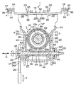
- FIG. 2 is a schematic cross-sectional view of the steering column device of FIG. 1 and corresponds to a cross-sectional view taken along the line II-II of FIG.
- 1st Embodiment it is sectional drawing of the inner side lower tube (1st tube) and the outer side upper tube (2nd tube) which comprise a steering column.
- 1st Embodiment it is a top view of a lower tube (1st tube), and the upper half part of the circumferential direction of a lower tube is shown.
- 1st Embodiment it is a bottom view of a lower tube (1st tube), and the lower half part of the circumferential direction of a lower tube is shown.
- It is a typical side view of the steering column apparatus of 2nd Embodiment of this invention, and has shown schematic structure of the steering column apparatus.
- 2nd Embodiment it is sectional drawing of the inner side upper tube (1st tube) and the outer side lower tube (2nd tube) which comprise a steering column.
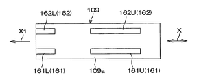
- 2nd Embodiment it is a top view of an upper tube (1st tube), and the upper half part of the circumferential direction of an upper tube is shown.
- 2nd Embodiment it is a bottom view of an upper tube (1st tube), and the lower half part of the circumferential direction of an upper tube is shown.
- It is a typical side view of the steering column apparatus of 3rd Embodiment of this invention, and has shown schematic structure of the steering column apparatus.
- 3rd Embodiment it is sectional drawing of the inner side lower tube (1st tube) and the outer side upper tube (2nd tube) which comprise a steering column.
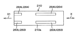
- 3rd Embodiment it is a top view of a lower tube (1st tube), and the upper half part of the circumferential direction of a lower tube is shown.
- 3rd Embodiment it is a bottom view of a lower tube (1st tube), and the lower half part of the circumferential direction of a lower tube is shown.
- It is a typical side view of the steering column apparatus of 4th Embodiment of this invention, and has shown schematic structure of the steering column apparatus.
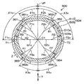
- it is sectional drawing of the inner side upper tube (1st tube) and the outer side lower tube (2nd tube) which comprise a steering column.
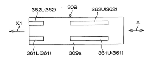
- 4th Embodiment it is a top view of an upper tube (1st tube), and the upper half part of the circumferential direction of an upper tube is shown.
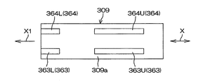
- it is a bottom view of an upper tube (1st tube), and the lower half part of the circumferential direction of an upper tube is shown.
- it is sectional drawing of the inner side lower tube (1st tube) and the outer side upper tube (2nd tube) which comprise a steering column.
- it is sectional drawing of the inner side upper tube (1st tube) and the outer side lower tube (2nd tube) which comprise a steering column.
- it is sectional drawing of the inner side lower tube (1st tube) and the outer side upper tube (2nd tube) which comprise a steering column.
- FIG. 1 is a schematic diagram showing a schematic configuration of a steering apparatus including a steering column apparatus according to a first embodiment of the present invention.
- a steering column device 1 shows a steering member 2 such as a steering wheel, a steering shaft 3 in which the steering member 2 is connected to one end (an upper end in the axial direction) so as to be integrally rotatable, and the steering shaft 3 is illustrated.
- a cylindrical steering column 4 that is rotatably supported via a non-supporting bearing.
- the other end (lower end in the axial direction) of the steering shaft 3 protrudes downward in the axial direction from the steering column 4 and is connected to a steering mechanism 6 such as a rack and pinion mechanism via an intermediate shaft 5 or the like. Yes.
- the steering mechanism 6 steers steered wheels (not shown) in conjunction with the steering of the steering member 2.
- the steering shaft 3 has an upper shaft 7 and a lower shaft 8 that are connected so as to be able to rotate together and to be relatively movable in the axial direction using, for example, spline coupling.
- the steering column 4 includes an upper tube 9 (second tube) that is an outer tube fitted so as to be relatively movable in the axial direction, and a lower tube 10 (first tube) that is an inner tube, and an axial lower end of the lower tube 10. And a connected housing 11.
- the housing 11 houses a speed reduction mechanism 13 that decelerates the power of the steering assisting electric motor 12 and transmits it to the lower shaft 8.
- the speed reduction mechanism 13 includes a drive gear 14 that is coupled to a rotation shaft (not shown) of the electric motor 12 so as to be able to rotate together with the drive gear 14 and a driven gear 15 that meshes with the drive gear 14 and rotates along with the lower shaft 8. .
- the steering column 4 is attached to vehicle body side members 18 and 19 (for example, a cross member) via an upper fixing bracket 16 disposed on the vehicle rear side and a lower fixing bracket 17 disposed on the vehicle front side.
- a lower column bracket 20 is fixed to the housing 11 of the steering column 4.
- the lower column bracket 20 is supported by a lower fixing bracket 17 fixed to the vehicle body side member 19 so as to be rotatable around the tilt center axis 21 via a tilt center axis 21 as a pivot axis.
- the entire steering column 4 can be rotated around the tilt center axis 21, and as a result, tilt adjustment for adjusting the height position of the steering member 2 is possible.
- the upper column bracket 22 is fixed to the upper tube 10 of the steering column 4.
- the upper column bracket 22 is lockable (tilt lock and telescopic lock) with respect to the support bracket 24 suspended and held by the upper fixing bracket 16 via the suspension mechanism 23.
- the steering column device 1 includes a lock mechanism 25 that achieves tilt lock and telescopic lock.
- the lock mechanism 25 includes an operation lever 26 that can be rotated, a long slot for tilt (not shown) provided in the side plate of the support bracket 24, and a long telescopic hole 27 provided in the side plate of the upper column bracket 22.
- the insertion operation lever 26 and a tightening shaft 28 that rotates integrally are provided.
- the lock mechanism 25 is held on the fastening shaft 28 and is a cam mechanism that achieves tilt lock and telescopic lock by pressing the side plates of the support bracket 24 and the upper column bracket 22 as the operation lever 26 rotates. (Not shown), and is provided so as to be rotatable integrally with the fastening shaft 28, and by pushing up the lower tube 10 through the opening 29 of the upper tube 9, both the tubes 9, 10 are fixed to lock the both tubes 9, 10. And a push-up cam 30 to be achieved.
- the upper fixing bracket 16 is provided with a main plate 32 formed with a long hole 31 extending in the column moving direction X1 (a direction parallel to the axial direction X) at the time of the secondary collision.
- Bolt insertion holes 34 are formed in the top plate 33 of the support bracket 24.
- the suspension mechanism 23 includes a suspension bolt 35 that passes through the long hole 31 and the bolt insertion hole 34, and a nut 36 that is coupled to the suspension bolt 35.
- the support bracket 24 is suspended by a suspension bolt 35 supported by the upper fixing bracket 16 and a nut 36 coupled to the suspension bolt 35.
- the steering column apparatus 1 will be described based on an example in which the steering column apparatus 1 is applied to an electric power steering apparatus.
- the present invention may be applied to a manual steering apparatus.
- the case where the steering column device 1 can be tilt-adjusted will be described.
- the present invention may be applied to a steering column device that does not have a tilt adjustment function.
- the present invention may be applied to an adjustable and telescopic adjustable steering column device.
- FIG. 2 is a sectional view taken along line II-II in FIG.
- the upper fixing bracket 16 includes a pair of attachment plates 37 extending outward from the main plate 32.
- the support bracket 24 includes the top plate 33 and a pair of side plates 38 extending downward in the tilt direction Y.
- the top plate 33 includes a first top plate 33A that connects the upper ends of the pair of side plates 38 in the tilt direction Y, and a second top plate 33B that is fixed to the upper surface of the first top plate 33A.
- a bolt insertion hole 34 through which the suspension bolt 35 is inserted is formed through both top plates 33A and 33B.
- the second top plate 33B includes a pair of attached plates 39 that extend outward.
- a fixing screw 40 that passes through each mounting plate 37 of the upper fixing bracket 16 and a corresponding mounting plate 39 of the support bracket 24 is fixed to the vehicle body side member 18.
- Each mounting plate 37 of the upper fixing bracket 16 is fixed to the vehicle body side member 18 by a fixing screw 40.
- Each mounting plate 37 and the corresponding mounted plate 39 are connected via resin pins 41 that can be passed through both plates 37 and 39 and can be broken during a secondary collision.
- the support bracket 24 is detached from the mounting position with respect to the upper fixing bracket 16 and moves in the column movement direction (the direction perpendicular to the paper surface in FIG. 2). (See X1).
- the upper column bracket 22 has a groove shape including a pair of side plates 42 respectively opposed to the pair of side plates 38 of the support bracket 24 and a connecting plate 43 that connects the lower ends of the pair of side plates 42 in the tilt direction Y. Yes.
- the tightening shaft 28 includes a bolt that penetrates the tilting long hole 44 of the side plate 38 of the support bracket 24 and the telescopic long hole 27 of the side plate 42 of the upper column bracket 22.
- a head 45 at one end of the fastening shaft 28 is fixed so as to rotate together with the operation lever 26.
- a nut 46 is screwed into a threaded portion provided at the other end of the fastening shaft 28.
- a cam mechanism 47 is provided between the operation lever 26 and one side plate 38 of the support bracket 24 to achieve tilt lock and telescopic lock as the operation lever 26 rotates.
- the cam mechanism 47 includes an annular first cam 48 and an annular second cam 49 supported by the shaft portion of the fastening shaft 28. Cam protrusions that engage with each other are formed on opposing surfaces of the first cam 48 and the second cam 49.
- the first cam 48 is connected to the operation lever 26 so as to be rotatable integrally with the operation lever 26, and movement in the axial direction relative to the fastening shaft 28 is restricted.
- the second cam 49 includes an annular plate as a fastening portion facing the other side plate 38 of the support bracket 24 and a boss extending from the annular plate. The rotation of the second cam 49 is restricted by inserting the boss of the second cam 49 into the tilting long hole 44 of the one side plate 38 of the support bracket 24.
- the second cam 49 is supported so as to be movable in the axial direction of the fastening shaft 28.
- the first interposed member 50 includes an annular plate facing the other side plate 38 of the support bracket 24 and a boss extending from the annular plate. Since the boss of the first interposed member 50 is inserted into the long slot 44 for tilting of the other side plate 38 of the support bracket 24, the rotation of the first interposed member 50 is restricted.
- the second interposed member 51 includes a washer 52 interposed between the nut 46 and the first interposed member 50, and a needle roller bearing 53 interposed between the washer 52 and the first interposed member 50.
- a sleeve 54 that rotates integrally with the fastening shaft 28 is fitted on the outer periphery of the shaft portion of the fastening shaft 28 by, for example, serration fitting.
- the push-up cam 30 is provided integrally with the sleeve 54.
- the first cam 48 rotates with respect to the second cam 49, whereby the second cam 49 is moved in the tightening axis direction K, and the second cam 49 and the first interposed member are moved.
- the side plates 38 of the support bracket 24 are clamped and tightened between the 50 annular plates.
- each side plate 38 of the support bracket 24 is pressed against the corresponding side plate 42 of the upper column bracket 22 to achieve tilt lock and telescopic lock.
- the push-up cam 30 pushes up the lower tube 10, the lock between the tubes 9 and 10 is achieved.
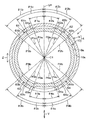
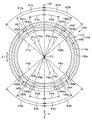
- An outer side upper tube 9 extends on the outer periphery 10a of the inner side lower tube 10 (first tube) in the axial direction (direction orthogonal to the paper surface in FIG. 2; axial direction X in FIG. 1). ) Is provided with a plurality of protrusions 61, 62, 63, 64. The plurality of protrusions 61 to 64 are arranged at unequal intervals in the circumferential direction Z so as to approach the vertical plane VP side including the central axis C1 of the lower tube 10.
- each of the protrusions 61 to 64 forms a contact area with the upper tube 9 in a predetermined range with respect to the circumferential direction Z of the lower tube 10.
- the protrusions 61 and 62 are disposed on both sides of the vertical plane VP in the upper half of the circumferential direction Z of the lower tube 10.
- the protrusion 61 and the protrusion 62 may be arranged symmetrically with respect to the vertical plane VP or may not be arranged symmetrically.
- the protrusion 63 and the protrusion 64 are disposed on the lower half of the circumferential direction Z of the lower tube 10 and are disposed on both sides of the vertical plane VP.
- the protrusions 63 and 64 are arranged on both sides of the vertical plane VP in the lower half of the circumferential direction Z of the lower tube 10.
- the protrusion 63 and the protrusion 64 may be arranged symmetrically with respect to the vertical plane VP or may not be arranged symmetrically.
- the contact region of the protrusion 61 with respect to the upper tube 9 includes a first end 61a on the side close to the vertical plane VP, a second end 61b on the side far from the vertical plane VP, and the first end 61a. And a central portion 61c between the second end portion 61b.
- An angle ⁇ 1c formed by a plane P1c including the central portion 61c of the protrusion 61 and the central axis C1 of the lower tube 10 and the vertical plane VP is set to 45 ° or less ( ⁇ 1c ⁇ 45 °).
- the angle ⁇ 1a formed between the plane P1a including the first end 61a of the protrusion 61 and the central axis C1 of the lower tube 10 and the vertical plane VP is 45 ° or less ( ⁇ 1a ⁇ 45 °). It is more preferable if the angle ⁇ 1b formed by the plane P1b including the second end portion 61b of the protrusion 61 and the central axis C1 of the lower tube 10 and the vertical plane VP is 45 ° or less ( ⁇ 1b ⁇ 45 °). .
- the contact region of the protrusion 62 with respect to the upper tube 9 includes a first end 62a closer to the vertical plane VP, a second end 62b farther from the vertical plane VP, and a first end 62a. And a central portion 62c between the second end portion 62b.
- An angle ⁇ 2c formed by a plane P2c including the central portion 62c of the protrusion 62 and the central axis C1 of the lower tube 10 and the vertical plane VP is set to 45 ° or less ( ⁇ 2c ⁇ 45 °).
- the angle ⁇ 2a formed by the plane P2a including the first end 62a of the protrusion 62 and the central axis C1 of the lower tube 10 and the vertical plane VP is 45 ° or less ( ⁇ 2a ⁇ 45 °). It is more preferable if the angle ⁇ 2b formed by the plane P2b including the second end 62b of the protrusion 62 and the central axis C1 of the lower tube 10 and the vertical plane VP is 45 ° or less ( ⁇ 2b ⁇ 45 °). .
- the contact region of the protrusion 63 with respect to the upper tube 9 includes a first end 63a on the side close to the vertical plane VP, a second end 63b on the side far from the vertical plane VP, and the first end 63a. And a central portion 63c between the second end portion 63b.
- An angle ⁇ 3c formed by a plane P3c including the central portion 63c of the protrusion 63 and the central axis C1 of the lower tube 10 and the vertical plane VP is set to 45 ° or less ( ⁇ 3c ⁇ 45 °).
- the angle ⁇ 3a formed by the plane P3a including the first end 63a of the protrusion 63 and the central axis C1 of the lower tube 10 and the vertical plane VP is 45 ° or less ( ⁇ 3a ⁇ 45 °). It is more preferable if the angle ⁇ 3b formed by the plane P3b including the second end 63b of the protrusion 63 and the central axis C1 of the lower tube 10 and the vertical plane VP is 45 ° or less ( ⁇ 3b ⁇ 45 °). .
- the contact region of the protrusion 64 with respect to the upper tube 9 includes a first end portion 64a on the side close to the vertical surface VP, a second end portion 64b on the side far from the vertical surface VP, and a first end portion 64a. And a central portion 64c between the second end portion 64b.
- An angle ⁇ 4c formed by a plane P4c including the central portion 64c of the protrusion 64 and the central axis C1 of the lower tube 10 and the vertical plane VP is set to 45 ° or less ( ⁇ 4c ⁇ 45 °). Thereby, it becomes arrangement
- the angle ⁇ 4a formed by the plane P4a including the first end portion 64a of the protrusion 64 and the central axis C1 of the lower tube 10 and the vertical plane VP is 45 ° or less ( ⁇ 4a ⁇ 45 °). It is more preferable if the angle ⁇ 4b formed by the plane P3b including the second end portion 64b of the protrusion 64 and the central axis C1 of the lower tube 10 and the vertical plane VP is 45 ° or less ( ⁇ 4b ⁇ 45 °). .
- the protrusions 61 and 62 are provided discontinuously in the axial direction X in the upper half of the circumferential direction of the lower tube 10. That is, the protrusion 61 includes a protrusion 61U above the axial direction X and a protrusion 61L below the axial direction X.
- the protrusion 62 includes an upper protrusion 62U in the axial direction X and a lower protrusion 62L in the axial direction X.
- the protrusions 63 and 64 are provided discontinuously in the axial direction X in the lower half of the circumferential direction of the lower tube 10. That is, the protrusion 63 includes an upper protrusion 63U in the axial direction X and a lower protrusion 63L in the axial direction X.
- the protrusion 64 includes an upper protrusion 64U in the axial direction X and a lower protrusion 64L in the axial direction X.
- the upper projections 61U and 62U in the axial direction X in the upper half of the circumferential direction and the lower projections 63L and 64L in the axial direction X in the lower half of the circumferential direction of the lower tube 10 are strongly pressed against the inner circumference 9a of the upper tube 9 It is done.
- the plurality of protrusions 61 to 64 provided on the outer periphery 10a of the lower tube 10 (first tube) and in contact with the inner periphery 9a of the upper tube 9 (second tube) are not aligned in the circumferential direction Z. It arrange
- planes P1c, P2c, and P3c including the center portions 61c, 62c, 63c, and 64c in the circumferential direction Z of the contact areas of the protrusions 61, 62, 63, and 64 and the central axis C1 of the lower tube 10 (first tube).
- P4c and the angle ⁇ 1c, ⁇ 2c, ⁇ 3c, ⁇ 4c formed by the vertical plane is 45 ° or less. Accordingly, the upper tube 9 (second tube) is substantially prevented from being wedged between the projections 61, 62; 63, 64 adjacent to each other with the vertical plane VP interposed therebetween. The variation in the sliding load can be suppressed.
- the planes P1b, P2b, P3b, P4b including the second end portions 61b, 62b, 63b, 64b of the contact areas of the protrusions 61, 62, 63, 64 and the central axis C1 of the lower tube 10 (first tube).
- the angles ⁇ 1b, ⁇ 2b, ⁇ 3b, and ⁇ 4b formed with the vertical plane VP are 45 ° or less.
- the contact areas of the protrusions 61 to 64 are arranged in a range where the central angle is 45 ° or less with respect to the vertical plane VP, so that the adjacent protrusions 61, 62; 63 sandwiching the vertical plane VP. 64, the upper tube 9 (second tube) can be prevented from being wedged. Thereby, the dispersion
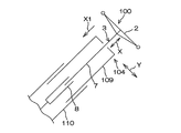
- FIG. 6 shows a schematic side view of the steering column device 100 according to the second embodiment of the present invention.
- the second embodiment of FIG. 6 is mainly different from the first embodiment of FIG. 1 in that the steering column 104 has an upper tube 109 (first tube) that is an inner tube and a lower tube 110 (that is an outer tube). 2nd tube) and the housing (not shown) connected with the axial direction lower end of the lower tube 110 (2nd tube).
- the outer side lower tube extends in the axial direction (direction perpendicular to the paper surface) to the outer periphery 109a of the inner side upper tube 109 (first tube).
- a plurality of protrusions 161, 162, 163, and 164 that are in contact with the outer periphery 110a of 110 (second tube) are provided.
- the plurality of protrusions 161 to 164 are arranged at unequal intervals in the circumferential direction Z so as to be closer to the vertical plane VP side including the central axis C1 of the upper tube 109.
- each of the protrusions 161 to 164 forms a contact area with the lower tube 110 in a predetermined range with respect to the circumferential direction Z of the upper tube 109.
- the protrusions 161 and 162 are arranged on both sides of the vertical plane VP in the upper half of the upper tube 109 in the circumferential direction Z.
- the protrusion 161 and the protrusion 162 may be arranged symmetrically with respect to the vertical plane VP, or may not be arranged symmetrically.
- the protrusions 163 and 164 are disposed in the lower half portion of the upper tube 109 in the circumferential direction Z and are disposed on both sides of the vertical plane VP.
- the protrusions 163 and 164 are arranged on both sides of the vertical plane VP in the lower half of the upper tube 109 in the circumferential direction Z.
- the protrusion 163 and the protrusion 164 may be arranged symmetrically with respect to the vertical plane VP or may not be arranged symmetrically.
- the contact region of the protrusion 161 with respect to the lower tube 110 includes a first end 161a on the side close to the vertical plane VP, a second end 161b on the side far from the vertical plane VP, and the first end 161a. And a central portion 161c between the second end portion 161b.
- An angle ⁇ 1c formed by a plane P1c including the central portion 161c of the protrusion 161 and the central axis C1 of the upper tube 109 and the vertical plane VP is set to 45 ° or less ( ⁇ 1c ⁇ 45 °).
- the angle ⁇ 1a formed by the plane P1a including the first end portion 161a of the protrusion 161 and the central axis C1 of the upper tube 109 and the vertical plane VP is 45 ° or less ( ⁇ 1a ⁇ 45 °).
- the angle ⁇ 1b formed by the plane P1b including the second end portion 161b of the protrusion 161 and the central axis C1 of the upper tube 109 and the vertical plane VP is 45 ° or less ( ⁇ 1b ⁇ 45 °).
- the contact region of the protrusion 162 with respect to the lower tube 110 includes a first end 162a on the side close to the vertical plane VP, a second end 162b on the side far from the vertical plane VP, and a first end 162a. And a central portion 162c between the second end portion 162b.
- An angle ⁇ 2c formed by a plane P2c including the central portion 162c of the protrusion 162 and the central axis C1 of the upper tube 109 and the vertical plane VP is set to 45 ° or less ( ⁇ 2c ⁇ 45 °).
- the angle ⁇ 2a formed by the plane P2a including the first end 162a of the protrusion 162 and the central axis C1 of the upper tube 109 and the vertical plane VP is 45 ° or less ( ⁇ 2a ⁇ 45 °).
- the angle ⁇ 2b formed by the plane P2b including the second end 162b of the protrusion 162 and the central axis C1 of the upper tube 109 and the vertical plane VP is 45 ° or less ( ⁇ 2b ⁇ 45 °).
- the contact region of the protrusion 163 with respect to the lower tube 110 includes a first end 163a on the side close to the vertical plane VP, a second end 163b on the side far from the vertical plane VP, and a first end 163a. And a central portion 163c between the second end portion 163b.
- An angle ⁇ 3c formed by a plane P3c including the central portion 163c of the protrusion 163 and the central axis C1 of the upper tube 109 and the vertical plane VP is set to 45 ° or less ( ⁇ 3c ⁇ 45 °).
- the projection 163 is arranged so as to be close to the vertical plane VP.
- the angle ⁇ 3a formed by the plane P3a including the first end 163a of the protrusion 163 and the central axis C1 of the upper tube 109 and the vertical plane VP is 45 ° or less ( ⁇ 3a ⁇ 45 °).
- the angle ⁇ 3b formed by the plane P3b including the second end 163b of the protrusion 163 and the central axis C1 of the upper tube 109 and the vertical plane VP is 45 ° or less ( ⁇ 3b ⁇ 45 °).
- the contact region of the protrusion 164 with respect to the lower tube 110 includes a first end 164a on the side close to the vertical plane VP, a second end 164b on the side far from the vertical plane VP, and a first end 164a. And a central portion 164c between the second end portion 164b.
- An angle ⁇ 4c formed by a plane P4c including the central portion 164c of the protrusion 164 and the central axis C1 of the upper tube 109 and the vertical plane VP is set to 45 ° or less ( ⁇ 4c ⁇ 45 °).
- an angle ⁇ 4a formed by a plane P4a including the first end 164a of the protrusion 164 and the central axis C1 of the upper tube 109 and the vertical plane VP is 45 ° or less ( ⁇ 4a ⁇ 45 °).
- the angle ⁇ 4b formed by the plane P3b including the second end 164b of the protrusion 164 and the central axis C1 of the upper tube 109 and the vertical plane VP is 45 ° or less ( ⁇ 4b ⁇ 45 °).
- the protrusions 161 and 62 are discontinuously provided in the axial direction X in the upper half of the upper tube 109 in the circumferential direction. That is, the protrusion 161 includes an upper protrusion 161U in the axial direction X and a lower protrusion 161L in the axial direction X.
- the protrusion 162 includes an upper protrusion 162U in the axial direction X and a lower protrusion 162L in the axial direction X.
- the protrusions 163 and 164 are discontinuously provided in the axial direction X in the lower half of the upper tube 109 in the circumferential direction. That is, the protrusion 163 includes a protrusion 163U above the axial direction X and a protrusion 163L below the axial direction X.
- the protrusion 164 includes an upper protrusion 164U in the axial direction X and a lower protrusion 164L in the axial direction X.
- the upper end side in the axial direction of the upper tube 109 is pushed down by the weight of the upper tube 109 or the weight of the steering member 2 or the like.
- the lower protrusions 161L and 162L in the axial direction X in the upper half of the circumferential direction and the upper protrusions 163U and 164U in the axial direction X of the lower half in the circumferential direction of the upper tube 109 strongly press against the inner periphery 110a of the lower tube 110. It is done.
- the plurality of protrusions 161 to 164 provided on the outer periphery 109a of the upper tube 109 (first tube) and in contact with the inner periphery 110a of the lower tube 110 (second tube) are not aligned in the circumferential direction Z. It arrange
- P4c and the angle ⁇ 1c, ⁇ 2c, ⁇ 3c, ⁇ 4c formed by the vertical plane is 45 ° or less. Accordingly, the lower tube 110 (second tube) is substantially prevented from being sandwiched between the protrusions 161, 162; 163, 164 adjacent to each other with the vertical plane VP interposed therebetween, so that the distance between the tubes 109, 110 is reduced. The variation in the sliding load can be suppressed.
- the planes P1b, P2b, P3b, P4b including the second ends 161b, 162b, 163b, 164b of the contact areas of the protrusions 161, 162, 163, 164 and the central axis C1 of the upper tube 109 (first tube).
- the angles ⁇ 1b, ⁇ 2b, ⁇ 3b, and ⁇ 4b formed with the vertical plane VP are 45 ° or less.
- the contact areas of the protrusions 161 to 164 are arranged in a range where the central angle is 45 ° or less with respect to the vertical plane VP. Therefore, the adjacent protrusions 161 and 162; 163 across the vertical plane VP. , 164, the lower tube 110 (second tube) can be prevented from being wedged. Thereby, the dispersion
- FIG. 10 shows a schematic side view of a steering column apparatus 300 according to the third embodiment of the present invention.
- the steering column 204 includes an upper tube 209 (second tube) that is an outer tube and a lower tube 210 (first tube) that is an inner tube.
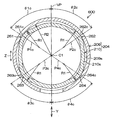
- FIG. 11 is a cross-sectional view of the steering column 204.
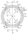
- the third embodiment is mainly different from the first embodiment of FIG. That is, a plurality of protrusions 261, 262, 263, and 264 (corresponding to the first protrusions) provided on the outer periphery 201 a of the lower tube 210 are respectively in a top section 261 c having a round cross section that contacts the inner periphery 209 a of the upper tube 209 262c, 263c, 264c.
- the curvature radius R1 of the top portions 261c, 262c, 263c, 264c of the protrusions 261, 262, 263, 264 is smaller than the curvature radius R2 of the inner periphery 209a of the upper tube 209 (R1 ⁇ R2).
- an angle ⁇ 1c formed by a plane P1c, P2c, P3c, P4c including the tops 261c, 262c, 263c, 264c of the protrusions 261, 262, 263, 264 and the central axis C1 of the lower tube 210 and the vertical plane VP, ⁇ 2c, ⁇ 3c, and ⁇ 4c are less than 45 ° ( ⁇ 1c ⁇ 45 °, ⁇ 2c ⁇ 45 °, ⁇ 3c ⁇ 45 °, ⁇ 4c ⁇ 45 °).
- the protrusions 261 and 262 are discontinuously provided in the axial direction X in the upper half portion in the circumferential direction of the lower tube 210. That is, the protrusion 261 includes an upper protrusion 261U in the axial direction X and a lower protrusion 261L in the axial direction X.
- the protrusion 262 includes an upper protrusion 262U in the axial direction X and a lower protrusion 262L in the axial direction 2X.
- the protrusions 263 and 264 are discontinuously provided in the axial direction X in the lower half portion in the circumferential direction of the lower tube 210. That is, the protrusion 263 includes a protrusion 263 ⁇ / b> U above the axial direction X and a protrusion 263 ⁇ / b> L below the axial direction X.
- the protrusion 264 includes an upper protrusion 264U in the axial direction X and a lower protrusion 264L in the axial direction X.
- the plurality of protrusions 261 to 264 provided on the outer periphery 210a of the lower tube 210 (first tube) and in contact with the inner periphery 209a of the upper tube 209 (second tube) are not aligned in the circumferential direction Z. It arrange
- FIG. Accordingly, when the tubes 209 and 210 slide relative to each other while the steering shaft 3 is pushed upward obliquely during a secondary collision, or when the tubes 209 and 210 slide relative to each other during telescopic adjustment, the sliding load Can be reduced, and variations in sliding load can be suppressed.
- top portions 261c to 264c of the protrusions 261 to 264 having a round cross section come into contact with the inner periphery 209a of the upper tube 209 (second tube) in a substantially line contact state. Variations can be suppressed. As a result, variation in sliding load between the tubes 209 and 210 can be reliably suppressed. Further, when the lower tube 210 is viewed from the axial direction, as shown in FIG. 11, the projections 261 to 264 are arranged in a range where the central angle is less than 45 ° with respect to the vertical plane VP.
- FIG. 14 has shown the typical side view of the steering column apparatus 300 of 4th Embodiment of this invention.
- the steering column 304 includes an upper tube 309 (first tube) that is an inner tube and a lower tube 310 (second tube) that is an outer tube.
- FIG. 15 is a cross-sectional view of the steering column 304.
- the fourth embodiment is mainly different from the second embodiment of FIG. That is, each of the protrusions 361, 362, 363, 364 (corresponding to the first protrusion) provided on the outer periphery 309a of the inner side upper tube 309 (first tube) is the outer side lower tube 310 (second tube). It includes top portions 361c, 362c, 363c, and 364c having a round cross section in contact with the inner periphery 310a.
- the curvature radius R1 of the top portions 361c, 362c, 363c, 364c of each protrusion 361, 362, 363, 364 is smaller than the curvature radius R2 of the inner periphery 310a of the lower tube 310 (R1 ⁇ R2).
- an angle ⁇ 1c formed by the plane P1c, P2c, P3c, P4c including the tops 361c, 362c, 363c, 364c of the protrusions 361, 362, 363, 364 and the central axis C1 of the upper tube 309 and the vertical plane VP, ⁇ 2c, ⁇ 3c, and ⁇ 4c are less than 45 ° ( ⁇ 1c ⁇ 45 °, ⁇ 2c ⁇ 45 °, ⁇ 3c ⁇ 45 °, ⁇ 4c ⁇ 45 °).
- the protrusions 361 and 362 are discontinuously provided in the axial direction X in the upper half of the upper tube 309 in the circumferential direction. That is, the protrusion 361 is configured by an upper protrusion 361U in the axial direction X and a lower protrusion 361L in the axial direction X.
- the protrusion 362 includes an upper protrusion 362U in the axial direction X and a lower protrusion 362L in the axial direction 2X.
- the protrusions 363 and 364 are discontinuously provided in the axial direction X in the lower half of the upper tube 309 in the circumferential direction. That is, the protrusion 363 is configured by a protrusion 363U above the axial direction X and a protrusion 363L below the axial direction X.
- the protrusion 364 includes an upper protrusion 364U in the axial direction X and a lower protrusion 364L in the axial direction X.
- the plurality of protrusions 361 to 364 provided on the outer periphery 309a of the upper tube 309 (first tube) and contacting the inner periphery 310a of the lower tube 310 (second tube) are not aligned in the circumferential direction Z. It arrange
- top portions 361c to 364c of the protrusions 361 to 364 having a round cross section come into contact with the inner periphery 310a of the lower tube 310 (second tube) in a substantially line contact state.
- Variations can be suppressed.
- variations in sliding load between the tubes 309 and 310 can be reliably suppressed.
- the projections 361 to 364 are arranged in a range where the central angle is less than 45 ° with respect to the vertical plane VP.
- FIG. 18 is a cross-sectional view of the steering column 404 of the steering column device 400 according to the fifth embodiment of the present invention.
- the fifth embodiment is mainly different from the third embodiment of FIG. 11 in the following. That is, a plurality of protrusions that are provided on the outer periphery 410a of the lower tube 410 (first tube) that is the inner tube and that contact the inner periphery 409a of the upper tube 409 (second tube) that is the outer tube are the first protrusions. And a plurality of second protrusions 71 and 72.
- Each of the second protrusions 71 and 72 includes top portions 71 c and 72 c having a round cross section that contact the inner periphery 409 a of the upper tube 409.
- the curvature radius R3 of the top portions 71c and 72c is smaller than the curvature radius R2 of the inner periphery 409a of the upper tube 409 (R3 ⁇ R2).
- Angles ⁇ 1c and ⁇ 2c formed by planes Q1c and Q2c including the top portions 71c and 72c of the second protrusions 71 and 72 and the central axis C1 of the lower tube 410 and the vertical plane VP are 45 ° or more and 90 ° or less ( 45 ° ⁇ ⁇ 1c ⁇ 90 °, 45 ° ⁇ ⁇ 2c ⁇ 90 °).
- the first protrusions 261 to 264 can suppress the sliding load between the tubes to be small during a secondary collision or telescopic adjustment. Furthermore, when the lower tube 410 is viewed from the axial direction, the second protrusions 71 and 72 arranged in the range of the central angle of 45 ° or more and 90 ° or less with respect to the vertical plane VP is used to move the steering column 404 in the left-right direction. Stiffness can be improved.
- FIG. 19 is a cross-sectional view of the steering column 504 of the steering column device 500 according to the sixth embodiment of the present invention.
- the sixth embodiment is mainly different from the fourth embodiment of FIG. 15 in the following. That is, a plurality of protrusions provided on the outer periphery 509a of the upper tube 509 (first tube) that is the inner tube and in contact with the inner periphery 510a of the lower tube 510 (second tube) that is the outer tube are the plurality of first protrusions.
- the projections 361 to 364 and a plurality of second projections 71 and 72 are included.
- Each of the second protrusions 71 and 72 includes top portions 71 c and 72 c having a round cross section that contact the inner periphery 409 a of the upper tube 409.
- the curvature radius R3 of the top portions 71c and 72c is smaller than the curvature radius R2 of the inner periphery 409a of the upper tube 409 (R3 ⁇ R2).
- Angles ⁇ 1c and ⁇ 2c formed by planes Q1c and Q2c including the top portions 71c and 72c of the second protrusions 71 and 72 and the central axis C1 of the upper tube 509 and the vertical plane VP are 45 ° or more and 90 ° or less ( 45 ° ⁇ ⁇ 1c ⁇ 90 °, 45 ° ⁇ ⁇ 2c ⁇ 90 °).
- the first protrusions 361 to 364 can suppress the sliding load between the tubes 509 and 510 at the time of secondary collision or telescopic adjustment. Further, when the upper tube 509 is viewed from the axial direction, the left and right directions of the steering column 504 are caused by the second protrusions 71 and 72 arranged in the range of the central angle of 45 ° or more and 90 ° or less with respect to the vertical plane VP. Stiffness can be improved.
- FIG. 20 shows a reference embodiment of the present invention. Referring to FIG. 20, this reference embodiment is different from the third embodiment of FIG. 11 as follows.
- the protrusions 261 to 264 are arranged at unequal intervals in the circumferential direction Z and approach the vertical plane VP side including the central axis C1 of the lower tube 210.
- Angles ⁇ 1c to ⁇ 4c formed by planes P1c to P4c including the top portions 261c to 264c of the protrusions 261 to 264 and the central axis C1 of the lower tube 210 and the vertical plane VP are less than 45 °.
- the protrusions 261 to 264 are not close to the vertical plane VP side including the central axis C1 of the lower tube 210.
- Angles ⁇ 1c to ⁇ 4c formed by planes P1c to P4c including the top portions 261c to 264c of the projections 261 to 264 and the central axis C1 of the lower tube 210 and the vertical plane VP are 45 ° or more and 90 ° or less.
- the left and right rigidity of the steering column can be improved by the protrusions 261 to 264.
- planes P1c to P4c including the tops 361c to 364c of the protrusions 361 to 364 and the central axis C1 of the upper tube 309
- Examples include those in which the angles ⁇ 1c to ⁇ 4c formed with the vertical plane VP are 45 ° or more and 90 ° or less.
- the present invention is not limited to the above-described embodiment, and the present invention can be variously modified within the scope of the claims.
- a steering column device that can suppress variation in sliding load is provided.
- Lower tube (first tube) 410a outer periphery 500 ... steering column device 504 ... steering column 509 ... upper tube (first tube) 509a ... outer periphery 510 ... lower tube (second tube) 510a ... inner circumference C1 ... center axis P1a, P2a, P3a, P4a ... (including the first end of the projection and the center axis) planes P1b, P2b, P3b, P4b ...
Landscapes
- Engineering & Computer Science (AREA)
- Chemical & Material Sciences (AREA)
- Combustion & Propulsion (AREA)
- Transportation (AREA)
- Mechanical Engineering (AREA)
- Steering Controls (AREA)
Abstract
ステアリングコラム装置が、軸方向に相対摺動可能に嵌め合わされ、ステアリングシャフトを回転可能に支持するインナー側の第1チューブおよびアウター側の第2チューブを備える。前記第1チューブの外周に、該第1チューブの軸方向に延びて前記第2チューブの内周に接触する複数の突起が設けられる。前記複数の突起は、前記第1チューブの中心軸線を含む鉛直面側に寄るように、該第1チューブの周方向に不等間隔を隔てて配置されている。
Description
本発明はステアリングコラム装置に関する。
互いに嵌合されてステアリングシャフトを支持するインナーチューブとアウターチューブとを備え、インナーチューブの外周の周方向に等間隔で設けられた複数の突起を、アウターチューブの内周に当接させて、両チューブを軸方向に相対摺動させるステアリング装置が提案されている(例えば特許文献1を参照)。
例えば、車両の二次衝突時等で、ステアリングシャフトが斜め上方に突き上げられつつ両チューブが相対摺動するときや、テレスコピック調整のために両チューブが相対摺動するとき等に、両チューブの摺動荷重がばらつくおそれがある。
そこで、本発明の目的は、摺動荷重のばらつきを抑制することができるステアリングコラム装置を提供することである。
そこで、本発明の目的は、摺動荷重のばらつきを抑制することができるステアリングコラム装置を提供することである。
前記目的を達成するため、請求項1の発明は、軸方向に相対摺動可能に嵌め合わされ、ステアリングシャフト(3)を回転可能に支持するインナー側の第1チューブ(10;109;210;309;410;509)およびアウター側の第2チューブ(9;110;209;310;409;510)を備え、前記第1チューブの外周(10a;109a;210a;309a;410a;509a)に、該第1チューブの軸方向(X)に延びて前記第2チューブの内周(9a;110a;209a;310a;409a;510a)に接触する複数の突起(61~64;161~164;261~264;361~364;71,261~264,71,72;361~364,71,72)が設けられ、前記複数の突起は、前記第1チューブの中心軸線(C1)を含む鉛直面(VP)側に寄るように、該第1チューブの周方向(Z)に不等間隔を隔てて配置されているステアリングコラム装置(1;100;200;300;400;500)を提供する。
なお、括弧内の英数字は、後述する実施形態における対応構成要素等を表すが、このことは、むろん、本発明がそれらの実施形態に限定されるべきことを意味するものではない。以下、この項において同じ。
また、請求項2のように、各前記突起(261~264;361~364)は、前記第2チューブの内周に接触する断面丸形の頂部(261c~264c;361c~364c)を含み、各前記突起の頂部の曲率半径(R1)は、前記第2チューブの内周の曲率半径(R2)よりも小さくされていてもよい。
また、請求項2のように、各前記突起(261~264;361~364)は、前記第2チューブの内周に接触する断面丸形の頂部(261c~264c;361c~364c)を含み、各前記突起の頂部の曲率半径(R1)は、前記第2チューブの内周の曲率半径(R2)よりも小さくされていてもよい。
また、請求項3のように、前記複数の突起は、複数の第1突起を含み、各前記第1突起の頂部と前記第1チューブの中心軸線とを含む平面(P1c~P4c)と、前記鉛直面とのなす角度(θ1c~θ4c)が、45°未満であってもよい。
また、請求項4のように、前記複数の突起は、複数の第2突起(71,72)を含み、各前記第2突起の頂部と前記第1チューブの中心軸線とを含む平面と、前記鉛直面とのなす角度(β1c,β2c)が、45°以上90°以下であってもよい。
また、請求項4のように、前記複数の突起は、複数の第2突起(71,72)を含み、各前記第2突起の頂部と前記第1チューブの中心軸線とを含む平面と、前記鉛直面とのなす角度(β1c,β2c)が、45°以上90°以下であってもよい。
また、請求項5のように、前記複数の突起は、複数の第1突起を含み、各前記第1突起は、第1チューブの周方向の所定の範囲に前記第2チューブに対する接触領域を形成しており、前記接触領域は、前記周方向に関して、前記鉛直面に近い側の第1端部(61a,62a,63a,64a;161a,162a,163a,164a)と、前記鉛直面から遠い側の第2端部(61b,62b,63b,64b;161b,162b,163b,164b)と、前記第1端部と前記第2端部間の中央部(61c,62c,63c,64c;161c,162c,163c,164c)と、を含み、各前記第1突起の中央部と前記第1チューブの中心軸線とを含む平面(P1c,P2c,P3c,P4c)と、前記鉛直面とのなす角度(θ1c,θ2c,θ3c,θ4c)が、45°以下であってもよい。
また、請求項6のように、各前記第1突起の第2端部と前記第1チューブの中心軸線とを含む平面(P1b,P2b,P3b,P4b)と、前記鉛直面とのなす角度(θ1b,θ2b,θ3b,θ4b)が、45°以下であってもよい。
また、請求項7のように、各前記突起は、前記第1チューブの軸方向に不連続に設けられていてもよい。
また、請求項7のように、各前記突起は、前記第1チューブの軸方向に不連続に設けられていてもよい。
また、請求項8のように、前記第1チューブはロアーチューブ(10;210;410)であり、前記第2チューブはアッパーチューブ(9;209;409)であってもよい。
また、請求項9のように、前記第1チューブはアッパーチューブ(109;309;509)であり、前記第2チューブはロアーチューブ(110;310;510)であってもよい。
また、請求項9のように、前記第1チューブはアッパーチューブ(109;309;509)であり、前記第2チューブはロアーチューブ(110;310;510)であってもよい。
請求項1の発明によれば、インナー側の第1チューブの外周に設けられてアウター側の第2チューブの内周に接触する複数の突起が、周方向に不等間隔を隔てて配置されて、第1チューブの中心軸線を含む鉛直面側に寄っているので、二次衝突時にステアリングシャフトが斜め上方へ突き上げられつつ両チューブが相対摺動するときや、テレスコピック調整のときに両チューブが相対摺動するときに、摺動荷重を小さくすることができ、摺動荷重のばらつきを抑制することができる。
請求項2の発明によれば、断面丸形の突起の頂部が第2チューブの内周に対して、実質的に線接触状態で接触するので、周方向に関する接触位置のばらつきを抑制することができる。その結果、両チューブ間の摺動荷重のばらつきを確実に抑制することができる。
請求項3の発明によれば、第1チューブを軸方向から見たときに、前記鉛直面を基準として中心角が45°未満の範囲に、各第1突起が配置されることになるので、鉛直面を挟んで隣接する第1突起間に、第2チューブが楔状に挟み込まれることを抑制することができる。その結果、二次衝突時やテレスコピック調整のときに、両チューブ間の摺動荷重のばらつきを確実に抑制することができる。
請求項3の発明によれば、第1チューブを軸方向から見たときに、前記鉛直面を基準として中心角が45°未満の範囲に、各第1突起が配置されることになるので、鉛直面を挟んで隣接する第1突起間に、第2チューブが楔状に挟み込まれることを抑制することができる。その結果、二次衝突時やテレスコピック調整のときに、両チューブ間の摺動荷重のばらつきを確実に抑制することができる。
請求項4の発明によれば、第1チューブを軸方向から見たときに、前記鉛直面を基準として中心角が45°以上90°以下の範囲に、第2突起が配置される。したがって、第1突起によって、二次衝突時やテレスコピック調整のときに両チューブ間の摺動荷重を小さく抑制しつつ、第2突起によって、左右方向の剛性を向上することができる。
また、請求項5の発明によれば、鉛直面を挟んで隣接する第1突起間に、第2チューブが楔状に挟み込まれることを実質的に抑制して、両チューブ間の摺動荷重のばらつきを抑制することができる。
また、請求項5の発明によれば、鉛直面を挟んで隣接する第1突起間に、第2チューブが楔状に挟み込まれることを実質的に抑制して、両チューブ間の摺動荷重のばらつきを抑制することができる。
また、請求項6の発明によれば、第1チューブを軸方向から見たときに、前記鉛直面を基準として中心角が45°以下の範囲に、各第1突起が配置されることになるので、鉛直面を挟んで隣接する第1突起間に、第2チューブが楔状に挟み込まれることを抑制することができる。これにより、両チューブ間の摺動荷重のばらつきを抑制することができる。
また、請求項7の発明によれば、両チューブ間に倒れを生じながら、両チューブが突起を介して摺動するときの摺動荷重のばらつきを抑制することができる。
また、請求項7の発明によれば、両チューブ間に倒れを生じながら、両チューブが突起を介して摺動するときの摺動荷重のばらつきを抑制することができる。
また、請求項8の発明によれば、アウターチューブをアッパー側とした一般的な構成に適用することができる。
また、請求項9の発明によれば、インナーチューブをアッパー側とした構成にも適用することができる。
また、請求項9の発明によれば、インナーチューブをアッパー側とした構成にも適用することができる。
本発明の好ましい実施形態の添付図面を参照しつつ説明する。
(第1実施形態)
図1は本発明の第1実施形態のステアリングコラム装置を含むステアリング装置の概略構成を示す模式図である。図1を参照して、ステアリングコラム装置1は、ステアリングホイール等の操舵部材2と、操舵部材2を一端(軸方向の上端)に一体回転可能に連結したステアリングシャフト3と、ステアリングシャフト3を図示しない軸受を介して回転可能に支持する筒状のステアリングコラム4とを備えている。
(第1実施形態)
図1は本発明の第1実施形態のステアリングコラム装置を含むステアリング装置の概略構成を示す模式図である。図1を参照して、ステアリングコラム装置1は、ステアリングホイール等の操舵部材2と、操舵部材2を一端(軸方向の上端)に一体回転可能に連結したステアリングシャフト3と、ステアリングシャフト3を図示しない軸受を介して回転可能に支持する筒状のステアリングコラム4とを備えている。
ステアリングシャフト3の他端(軸方向の下端)は、ステアリングコラム4から軸方向下方へ突出しており、インタミーディエイトシャフト5等を介して、ラックアンドピニオン機構等のステアリング機構6に連結されている。ステアリング機構6は、操舵部材2の操舵に連動して転舵輪(図示せず)を転舵する。
ステアリングシャフト3は、例えばスプライン結合を用いて、同行回転可能に且つ軸方向に相対移動可能に連結されたアッパーシャフト7およびロアーシャフト8を有している。
ステアリングシャフト3は、例えばスプライン結合を用いて、同行回転可能に且つ軸方向に相対移動可能に連結されたアッパーシャフト7およびロアーシャフト8を有している。
ステアリングコラム4は、軸方向に相対移動可能に嵌め合わされたアウターチューブであるアッパーチューブ9(第2チューブ)およびインナーチューブであるロアーチューブ10(第1チューブ)と、ロアーチューブ10の軸方向下端に連結されたハウジング11とを備えている。
ハウジング11内には、操舵補助用の電動モータ12の動力を減速してロアーシャフト8に伝達する減速機構13が収容されている。減速機構13は、電動モータ12の回転軸(図示せず)と同行回転可能に連結された駆動ギヤ14と、駆動ギヤ14に噛み合いロアーシャフト8と同行回転する被動ギヤ15とを有している。
ハウジング11内には、操舵補助用の電動モータ12の動力を減速してロアーシャフト8に伝達する減速機構13が収容されている。減速機構13は、電動モータ12の回転軸(図示せず)と同行回転可能に連結された駆動ギヤ14と、駆動ギヤ14に噛み合いロアーシャフト8と同行回転する被動ギヤ15とを有している。
ステアリングコラム4は、車両後方側に配置されたアッパ固定ブラケット16および車両前方側に配置されたロアー固定ブラケット17を介して、車体側部材18,19(例えばクロスメンバー等)に取り付けられている。
ステアリングコラム4のハウジング11には、ロアーコラムブラケット20が固定されている。ロアーコラムブラケット20は、車体側部材19に固定されたロアー固定ブラケット17に、ピボット軸としてのチルト中心軸21を介してチルト中心軸21の回りに回転可能に支持されている。これにより、ステアリングコラム4の全体がチルト中心軸21の回りに回転可能とされ、その結果、操舵部材2の高さ位置を調整するチルト調整が可能となっている。また、ステアリングコラム4のロアーチューブ10(第1チューブ)に対してアッパーチューブ9(第2チューブ)を軸方向Xに移動させて、操舵部材2の高さ位置を調整するテレスコ調整が可能となっている。
ステアリングコラム4のハウジング11には、ロアーコラムブラケット20が固定されている。ロアーコラムブラケット20は、車体側部材19に固定されたロアー固定ブラケット17に、ピボット軸としてのチルト中心軸21を介してチルト中心軸21の回りに回転可能に支持されている。これにより、ステアリングコラム4の全体がチルト中心軸21の回りに回転可能とされ、その結果、操舵部材2の高さ位置を調整するチルト調整が可能となっている。また、ステアリングコラム4のロアーチューブ10(第1チューブ)に対してアッパーチューブ9(第2チューブ)を軸方向Xに移動させて、操舵部材2の高さ位置を調整するテレスコ調整が可能となっている。
ステアリングコラム4のアッパーチューブ10には、アッパーコラムブラケット22が固定されている。アッパーコラムブラケット22は、アッパー固定ブラケット16に吊り下げ機構23を介して吊り下げ保持されたサポートブラケット24に対して、ロック可能(チルトロックおよびテレスコロック)である。ステアリングコラム装置1は、チルトロックおよびテレスコロックを達成するロック機構25を備えている。
ロック機構25は、回転操作可能な操作レバー26と、サポートブラケット24の側板に設けられたチルト用長孔(図示せず)とアッパーコラムブラケット22の側板に設けられたテレスコ用長孔27とを挿通し操作レバー26と一体回転する締付軸28とを備えている。
また、ロック機構25は、締付軸28上に保持され操作レバー26の回転操作に伴ってサポートブラケット24およびアッパーコラムブラケット22の側板を圧接してチルトロックおよびテレスコロックを達成するカム機構(図示せず)と、締付軸28と一体回転可能に設けられ、アッパーチューブ9の開口29を通してロアーチューブ10を押し上げることにより両チューブ9,10を止定して両チューブ9,10間のロックを達成する押上カム30とを備えている。
また、ロック機構25は、締付軸28上に保持され操作レバー26の回転操作に伴ってサポートブラケット24およびアッパーコラムブラケット22の側板を圧接してチルトロックおよびテレスコロックを達成するカム機構(図示せず)と、締付軸28と一体回転可能に設けられ、アッパーチューブ9の開口29を通してロアーチューブ10を押し上げることにより両チューブ9,10を止定して両チューブ9,10間のロックを達成する押上カム30とを備えている。
アッパー固定ブラケット16には、二次衝突時のコラム移動方向X1(軸方向Xとは平行な方向)に延びる長孔31が形成された主板32を備えている。サポートブラケット24の天板33には、ボルト挿通孔34が形成されている。吊り下げ機構23は、長孔31およびボルト挿通孔34を挿通する吊り下げボルト35と、吊り下げボルト35に結合されたナット36とを備えている。アッパー固定ブラケット16によって支持された吊り下げボルト35と、吊り下げボルト35に結合されたナット36とによって、サポートブラケット24が吊り下げられている。
本実施の形態では、ステアリングコラム装置1が電動パワーステアリング装置に適用された例に則して説明するが、本発明をマニュアルステアリング装置に適用するようにしてもよい。また、本実施の形態では、ステアリングコラム装置1がチルト調節可能である場合に則して説明するが、本発明をチルト調整機能を持たないステアリングコラム装置に適用するようにしてもよいし、チルト調整可能でテレスコピック調整可能なステアリングコラム装置に適用してもよい。
図2は図1のII-II線に沿う断面図である。図2を参照して、アッパー固定ブラケット16は、主板32から外側方に延設された一対の取付板37を備えている。
サポートブラケット24は、前記天板33と、チルト方向Yの下方に延びる一対の側板38を備えている。天板33は、一対の側板38のチルト方向Yの上端間を連結した第1天板33Aと、第1天板33Aの上面に固定された第2天板33Bとを備えている。吊り下げボルト35が挿通するボルト挿通孔34は、両天板33A,33Bを貫いて形成されてている。第2天板33Bは、外側方に延設された一対の被取付板39を備えている。
サポートブラケット24は、前記天板33と、チルト方向Yの下方に延びる一対の側板38を備えている。天板33は、一対の側板38のチルト方向Yの上端間を連結した第1天板33Aと、第1天板33Aの上面に固定された第2天板33Bとを備えている。吊り下げボルト35が挿通するボルト挿通孔34は、両天板33A,33Bを貫いて形成されてている。第2天板33Bは、外側方に延設された一対の被取付板39を備えている。
アッパー固定ブラケット16の各取付板37とサポートブラケット24の対応する被取付板39を挿通する固定ねじ40が、車体側部材18に固定されている。アッパー固定ブラケット16の各取付板37は、固定ねじ40によって車体側部材18に固定されている。
各取付板37と対応する被取付板39とは、両板37,39を挿通し二次衝突時に破断可能な樹脂ピン41を介して連結されている。二次衝突時に、樹脂ピン41の破断に伴って、サポートブラケット24が、アッパー固定ブラケット16に対する取付位置から離脱してコラム移動方向(図2において紙面とは直交する方向。図1のコラム移動方向X1を参照。)に移動する。
各取付板37と対応する被取付板39とは、両板37,39を挿通し二次衝突時に破断可能な樹脂ピン41を介して連結されている。二次衝突時に、樹脂ピン41の破断に伴って、サポートブラケット24が、アッパー固定ブラケット16に対する取付位置から離脱してコラム移動方向(図2において紙面とは直交する方向。図1のコラム移動方向X1を参照。)に移動する。
アッパーコラムブラケット22は、サポートブラケット24の一対の側板38にそれぞれ対向する一対の側板42と、一対の側板42のチルト方向Yの下端間を連結する連結板43とを備えた溝形をなしている。
締付軸28は、サポートブラケット24の側板38のチルト用長孔44およびアッパーコラムブラケット22の側板42のテレスコ用長孔27を貫通するボルトからなる。締付軸28の一端の頭部45は、操作レバー26と一体回転可能に固定されている。締付軸28の他端に設けられたねじ部にナット46が螺合している。
締付軸28は、サポートブラケット24の側板38のチルト用長孔44およびアッパーコラムブラケット22の側板42のテレスコ用長孔27を貫通するボルトからなる。締付軸28の一端の頭部45は、操作レバー26と一体回転可能に固定されている。締付軸28の他端に設けられたねじ部にナット46が螺合している。
操作レバー26とサポートブラケット24の一方の側板38との間には、操作レバー26の回転操作に伴って、チルトロックおよびテレスコロックを達成するカム機構47が介在している。カム機構47は、締付軸28の軸部により支持された環状の第1カム48と環状の第2カム49とを備えている。第1カム48と第2カム49との対向面には、互いに係合するカム突起が形成されている。
第1カム48は、操作レバー26と一体回転可能に連結され、締付軸28に対する軸方向移動が規制されている。第2カム49は、サポートブラケット24の他方の側板38に対向する締付部としての環状板と、環状板から延びるボスとを備えている。第2カム49のボスが、サポートブラケット24の一方の側板38のチルト用長孔44に挿入されることにより、第2カム49の回転が規制されている。第2カム49は、締付軸28の軸方向に移動可能に支持されている。
ナット46とサポートブラケット24の他方の側板38との間には、締付軸28により支持された環状の第1介在部材50と環状の第2介在部材51とが介在している。第1介在部材50は、サポートブラケット24の他方の側板38に対向する環状板と、環状板から延びるボスとを備えている。第1介在部材50のボスが、サポートブラケット24の他方の側板38のチルト用長孔44に挿通されることより、第1介在部材50の回転が規制されている。
第2介在部材51は、ナット46と第1介在部材50との間に介在するワッシャ52と、ワッシャ52と第1介在部材50との間に介在する針状ころ軸受53とを備えている。
締付軸28の軸部の外周には、例えばセレーション嵌合により締付軸28と一体回転するスリーブ54が嵌合している。前記の押上カム30は、スリーブ54と一体に設けられている。
締付軸28の軸部の外周には、例えばセレーション嵌合により締付軸28と一体回転するスリーブ54が嵌合している。前記の押上カム30は、スリーブ54と一体に設けられている。
操作レバー26の回転に伴って、第1カム48が第2カム49に対して回転することにより、第2カム49が締付軸方向Kに移動されて、第2カム49および第1介在部材50の環状板間で、サポートブラケット24の側板38が挟持されて締め付けられる。これにより、サポートブラケット24の各側板38が、アッパーコラムブラケット22の対応する側板42に圧接されて、チルトロックおよびテレスコロックが達成される。また、押上カム30がロアーチューブ10を押し上げることにより、両チューブ9,10間のロックが達成される。
インナー側のロアーチューブ10(第1チューブ)の外周10aに、軸方向(図2において紙面とは直交する方向。図1の軸方向X)に延びて、アウター側のアッパーチューブ9(第2チューブ)の内周9aに接触する複数の突起61,62,63,64が設けられている。複数の突起61~64は、ロアーチューブ10の中心軸線C1を含む鉛直面VP側に寄るように、周方向Zに不等間隔を隔てて配置されている。
具体的には、図3に示すように、各突起61~64は、ロアーチューブ10の周方向Zに関して所定の範囲にアッパーチューブ9に対する接触領域を形成している。突起61と突起62は、ロアーチューブ10の周方向Zの上半部において、鉛直面VPを挟んだ両側に配置されている。突起61と突起62とは、鉛直面VPに対して対称に配置されていてもよいし、対称に配置されていなくてもよい。
突起63と突起64は、ロアーチューブ10の周方向Zの下半部に配置されて、鉛直面VPを挟んだ両側に配置されている。突起63と突起64は、ロアーチューブ10の周方向Zの下半部において、鉛直面VPを挟んだ両側に配置されている。突起63と突起64とは、鉛直面VPに対して対称に配置されていてもよいし、対称に配置されていなくてもよい。
アッパーチューブ9に対する突起61の接触領域は、周方向Zに関して、鉛直面VPに近い側の第1端部61aと、鉛直面VPから遠い側の第2端部61bと、第1端部61aと第2端部61bとの間の中央部61cとを備えている。
突起61の中央部61cとロアーチューブ10の中心軸線C1とを含む平面P1cと、鉛直面VPとのなす角度θ1cが、45°以下とされている(θ1c≦45°)。これにより、突起61が鉛直面VPに寄るような配置となる。また、必然的に、突起61の第1端部61aとロアーチューブ10の中心軸線C1とを含む平面P1aと、鉛直面VPとのなす角度θ1aが、45°以下となる(θ1a≦45°)。なお、突起61の第2端部61bとロアーチューブ10の中心軸線C1とを含む平面P1bと、鉛直面VPとのなす角度θ1bが、45°以下(θ1b≦45°)であれば、より好ましい。
突起61の中央部61cとロアーチューブ10の中心軸線C1とを含む平面P1cと、鉛直面VPとのなす角度θ1cが、45°以下とされている(θ1c≦45°)。これにより、突起61が鉛直面VPに寄るような配置となる。また、必然的に、突起61の第1端部61aとロアーチューブ10の中心軸線C1とを含む平面P1aと、鉛直面VPとのなす角度θ1aが、45°以下となる(θ1a≦45°)。なお、突起61の第2端部61bとロアーチューブ10の中心軸線C1とを含む平面P1bと、鉛直面VPとのなす角度θ1bが、45°以下(θ1b≦45°)であれば、より好ましい。
アッパーチューブ9に対する突起62の接触領域は、周方向Zに関して、鉛直面VPに近い側の第1端部62aと、鉛直面VPから遠い側の第2端部62bと、第1端部62aと第2端部62bとの間の中央部62cとを備えている。
突起62の中央部62cとロアーチューブ10の中心軸線C1とを含む平面P2cと、鉛直面VPとのなす角度θ2cが、45°以下とされている(θ2c≦45°)。これにより、突起62が鉛直面VPに寄るような配置となる。また、必然的に、突起62の第1端部62aとロアーチューブ10の中心軸線C1とを含む平面P2aと、鉛直面VPとのなす角度θ2aが、45°以下となる(θ2a≦45°)。なお、突起62の第2端部62bとロアーチューブ10の中心軸線C1とを含む平面P2bと、鉛直面VPとのなす角度θ2bが、45°以下(θ2b≦45°)であれば、より好ましい。
突起62の中央部62cとロアーチューブ10の中心軸線C1とを含む平面P2cと、鉛直面VPとのなす角度θ2cが、45°以下とされている(θ2c≦45°)。これにより、突起62が鉛直面VPに寄るような配置となる。また、必然的に、突起62の第1端部62aとロアーチューブ10の中心軸線C1とを含む平面P2aと、鉛直面VPとのなす角度θ2aが、45°以下となる(θ2a≦45°)。なお、突起62の第2端部62bとロアーチューブ10の中心軸線C1とを含む平面P2bと、鉛直面VPとのなす角度θ2bが、45°以下(θ2b≦45°)であれば、より好ましい。
アッパーチューブ9に対する突起63の接触領域は、周方向Zに関して、鉛直面VPに近い側の第1端部63aと、鉛直面VPから遠い側の第2端部63bと、第1端部63aと第2端部63bとの間の中央部63cとを備えている。
突起63の中央部63cとロアーチューブ10の中心軸線C1とを含む平面P3cと、鉛直面VPとのなす角度θ3cが、45°以下とされている(θ3c≦45°)。これにより、突起63が鉛直面VPに寄るような配置となる。また、必然的に、突起63の第1端部63aとロアーチューブ10の中心軸線C1とを含む平面P3aと、鉛直面VPとのなす角度θ3aが、45°以下となる(θ3a≦45°)。なお、突起63の第2端部63bとロアーチューブ10の中心軸線C1とを含む平面P3bと、鉛直面VPとのなす角度θ3bが、45°以下(θ3b≦45°)であれば、より好ましい。
突起63の中央部63cとロアーチューブ10の中心軸線C1とを含む平面P3cと、鉛直面VPとのなす角度θ3cが、45°以下とされている(θ3c≦45°)。これにより、突起63が鉛直面VPに寄るような配置となる。また、必然的に、突起63の第1端部63aとロアーチューブ10の中心軸線C1とを含む平面P3aと、鉛直面VPとのなす角度θ3aが、45°以下となる(θ3a≦45°)。なお、突起63の第2端部63bとロアーチューブ10の中心軸線C1とを含む平面P3bと、鉛直面VPとのなす角度θ3bが、45°以下(θ3b≦45°)であれば、より好ましい。
アッパーチューブ9に対する突起64の接触領域は、周方向Zに関して、鉛直面VPに近い側の第1端部64aと、鉛直面VPから遠い側の第2端部64bと、第1端部64aと第2端部64bとの間の中央部64cとを備えている。
突起64の中央部64cとロアーチューブ10の中心軸線C1とを含む平面P4cと、鉛直面VPとのなす角度θ4cが、45°以下とされている(θ4c≦45°)。これにより、突起64が鉛直面VPに寄るような配置となる。また、必然的に、突起64の第1端部64aとロアーチューブ10の中心軸線C1とを含む平面P4aと、鉛直面VPとのなす角度θ4aが、45°以下となる(θ4a≦45°)。なお、突起64の第2端部64bとロアーチューブ10の中心軸線C1とを含む平面P3bと、鉛直面VPとのなす角度θ4bが、45°以下(θ4b≦45°)であれば、より好ましい。
突起64の中央部64cとロアーチューブ10の中心軸線C1とを含む平面P4cと、鉛直面VPとのなす角度θ4cが、45°以下とされている(θ4c≦45°)。これにより、突起64が鉛直面VPに寄るような配置となる。また、必然的に、突起64の第1端部64aとロアーチューブ10の中心軸線C1とを含む平面P4aと、鉛直面VPとのなす角度θ4aが、45°以下となる(θ4a≦45°)。なお、突起64の第2端部64bとロアーチューブ10の中心軸線C1とを含む平面P3bと、鉛直面VPとのなす角度θ4bが、45°以下(θ4b≦45°)であれば、より好ましい。
また、ロアーチューブ10の平面図である図4に示されるように、ロアーチューブ10の周方向の上半部において、各突起61,62は、軸方向Xに不連続に設けられている。すなわち、突起61は、軸方向Xの上方の突起61Uと、軸方向Xの下方の突起61Lとで構成されている。突起62は、軸方向Xの上方の突起62Uと、軸方向Xの下方の突起62Lとで構成されている。
また、ロアーチューブ10の底面図である図5に示されるように、ロアーチューブ10の周方向の下半部において、各突起63,64は、軸方向Xに不連続に設けられている。すなわち、突起63は、軸方向Xの上方の突起63Uと、軸方向Xの下方の突起63Lとで構成されている。突起64は、軸方向Xの上方の突起64Uと、軸方向Xの下方の突起64Lとで構成されている。
図示していないが、二次衝突時には、アッパーチューブ9の軸方向の上端が斜め上方へ突き上げられるために、ロアーチューブ10の周方向上半部における軸方向Xの下方の突起61L,62Lと、ロアーチューブ10の周方向下半部における軸方向Xの上方の突起63U,64Uが、アッパーチューブ9の内周9aに強く押し付けられる。
一方、テレスコ調整のためにロック機構25によるロックが解除された時には、アッパーチューブ9の軸方向の上端側が、アッパーチューブ9の自重や操舵部材2等の自重によって押し下げられるために、ロアーチューブ10の周方向上半部における軸方向Xの上方の突起61U,62Uと、ロアーチューブ10の周方向下半部における軸方向Xの下方の突起63L,64Lが、アッパーチューブ9の内周9aに強く押し付けられる。
一方、テレスコ調整のためにロック機構25によるロックが解除された時には、アッパーチューブ9の軸方向の上端側が、アッパーチューブ9の自重や操舵部材2等の自重によって押し下げられるために、ロアーチューブ10の周方向上半部における軸方向Xの上方の突起61U,62Uと、ロアーチューブ10の周方向下半部における軸方向Xの下方の突起63L,64Lが、アッパーチューブ9の内周9aに強く押し付けられる。
本実施形態によれば、ロアーチューブ10(第1チューブ)の外周10aに設けられてアッパーチューブ9(第2チューブ)の内周9aに接触する複数の突起61~64が、周方向Zに不等間隔を隔てて配置されて、ロアーチューブ10の中心軸線C1を含む鉛直面VP側に寄っている。したがって、二次衝突時にステアリングシャフト3が斜め上方へ突き上げられつつ両チューブ9,10が相対摺動するときや、テレスコピック調整のときに両チューブ9,10が相対摺動するときに、摺動荷重を小さくすることができ、摺動荷重のばらつきを抑制することができる。
また、各突起61,62,63,64の接触領域の周方向Zに関する中央部61c,62c,63c,64cとロアーチューブ10(第1チューブ)の中心軸線C1とを含む平面P1c,P2c,P3c,P4cと、鉛直面とのなす角度θ1c,θ2c,θ3c,θ4cが、45°以下である。これにより、鉛直面VPを挟んで隣接する突起61,62;63,64間に、アッパーチューブ9(第2チューブ)が楔状に挟み込まれることを実質的に抑制して、両チューブ9,10間の摺動荷重のばらつきを抑制することができる。
また、各突起61,62,63,64の接触領域の第2端部61b,62b,63b,64bとロアーチューブ10(第1チューブ)の中心軸線C1とを含む平面P1b,P2b,P3b,P4bと、鉛直面VPとのなす角度θ1b,θ2b,θ3b,θ4bが、45°以下である。これにより、鉛直面VPを基準として中心角が45°以下の範囲に、各突起61~64の接触領域が配置されることになるので、鉛直面VPを挟んで隣接する突起61,62;63,64間に、アッパーチューブ9(第2チューブ)が楔状に挟み込まれることを抑制することができる。これにより、両チューブ9,10間の摺動荷重のばらつきを抑制することができる。
また、両チューブ9,10間に倒れを生じながら、両チューブ9,10が、突起61~64を介して摺動するときの摺動荷重のばらつきを抑制することができる。
(第2実施形態)
次いで、図6は、本発明の第2実施形態のステアリングコラム装置100の模式的側面図を示している。図6の第2実施形態が、図1の第1実施形態と主に異なるのは、ステアリングコラム104が、インナーチューブであるアッパーチューブ109(第1チューブ)と、アウターチューブであるロアーチューブ110(第2チューブ)と、ロアーチューブ110(第2チューブ)の軸方向下端に連結されたハウジング(図示せず)とを備えている点である。
(第2実施形態)
次いで、図6は、本発明の第2実施形態のステアリングコラム装置100の模式的側面図を示している。図6の第2実施形態が、図1の第1実施形態と主に異なるのは、ステアリングコラム104が、インナーチューブであるアッパーチューブ109(第1チューブ)と、アウターチューブであるロアーチューブ110(第2チューブ)と、ロアーチューブ110(第2チューブ)の軸方向下端に連結されたハウジング(図示せず)とを備えている点である。
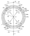
ステアリングコラム104の断面図である図7に示すように、インナー側のアッパーチューブ109(第1チューブ)の外周109aに、軸方向(紙面とは直交する方向)に延びて、アウター側のロアーチューブ110(第2チューブ)の外周110aに接触する複数の突起161,162,163,164が設けられている。複数の突起161~164は、アッパーチューブ109の中心軸線C1を含む鉛直面VP側に寄るように、周方向Zに不等間隔を隔てて配置されている。
具体的には、図7に示すように、各突起161~164は、アッパーチューブ109の周方向Zに関して所定の範囲にロアーチューブ110に対する接触領域を形成している。突起161と突起162は、アッパーチューブ109の周方向Zの上半部において、鉛直面VPを挟んだ両側に配置されている。突起161と突起162とは、鉛直面VPに対して対称に配置されていてもよいし、対称に配置されていなくてもよい。
突起163と突起164は、アッパーチューブ109の周方向Zの下半部に配置されて、鉛直面VPを挟んだ両側に配置されている。突起163と突起164は、アッパーチューブ109の周方向Zの下半部において、鉛直面VPを挟んだ両側に配置されている。突起163と突起164とは、鉛直面VPに対して対称に配置されていてもよいし、対称に配置されていなくてもよい。
ロアーチューブ110に対する突起161の接触領域は、周方向Zに関して、鉛直面VPに近い側の第1端部161aと、鉛直面VPから遠い側の第2端部161bと、第1端部161aと第2端部161bとの間の中央部161cとを備えている。
突起161の中央部161cとアッパーチューブ109の中心軸線C1とを含む平面P1cと、鉛直面VPとのなす角度θ1cが、45°以下とされている(θ1c≦45°)。これにより、突起161が鉛直面VPに寄るような配置となる。また、必然的に、突起161の第1端部161aとアッパーチューブ109の中心軸線C1とを含む平面P1aと、鉛直面VPとのなす角度θ1aが、45°以下となる(θ1a≦45°)。なお、突起161の第2端部161bとアッパーチューブ109の中心軸線C1とを含む平面P1bと、鉛直面VPとのなす角度θ1bが、45°以下(θ1b≦45°)であれば、より好ましい。
突起161の中央部161cとアッパーチューブ109の中心軸線C1とを含む平面P1cと、鉛直面VPとのなす角度θ1cが、45°以下とされている(θ1c≦45°)。これにより、突起161が鉛直面VPに寄るような配置となる。また、必然的に、突起161の第1端部161aとアッパーチューブ109の中心軸線C1とを含む平面P1aと、鉛直面VPとのなす角度θ1aが、45°以下となる(θ1a≦45°)。なお、突起161の第2端部161bとアッパーチューブ109の中心軸線C1とを含む平面P1bと、鉛直面VPとのなす角度θ1bが、45°以下(θ1b≦45°)であれば、より好ましい。
ロアーチューブ110に対する突起162の接触領域は、周方向Zに関して、鉛直面VPに近い側の第1端部162aと、鉛直面VPから遠い側の第2端部162bと、第1端部162aと第2端部162bとの間の中央部162cとを備えている。
突起162の中央部162cとアッパーチューブ109の中心軸線C1とを含む平面P2cと、鉛直面VPとのなす角度θ2cが、45°以下とされている(θ2c≦45°)。これにより、突起162が鉛直面VPに寄るような配置となる。また、必然的に、突起162の第1端部162aとアッパーチューブ109の中心軸線C1とを含む平面P2aと、鉛直面VPとのなす角度θ2aが、45°以下となる(θ2a≦45°)。なお、突起162の第2端部162bとアッパーチューブ109の中心軸線C1とを含む平面P2bと、鉛直面VPとのなす角度θ2bが、45°以下(θ2b≦45°)であれば、より好ましい。
突起162の中央部162cとアッパーチューブ109の中心軸線C1とを含む平面P2cと、鉛直面VPとのなす角度θ2cが、45°以下とされている(θ2c≦45°)。これにより、突起162が鉛直面VPに寄るような配置となる。また、必然的に、突起162の第1端部162aとアッパーチューブ109の中心軸線C1とを含む平面P2aと、鉛直面VPとのなす角度θ2aが、45°以下となる(θ2a≦45°)。なお、突起162の第2端部162bとアッパーチューブ109の中心軸線C1とを含む平面P2bと、鉛直面VPとのなす角度θ2bが、45°以下(θ2b≦45°)であれば、より好ましい。
ロアーチューブ110に対する突起163の接触領域は、周方向Zに関して、鉛直面VPに近い側の第1端部163aと、鉛直面VPから遠い側の第2端部163bと、第1端部163aと第2端部163bとの間の中央部163cとを備えている。
突起163の中央部163cとアッパーチューブ109の中心軸線C1とを含む平面P3cと、鉛直面VPとのなす角度θ3cが、45°以下とされている(θ3c≦45°)。これにより、突起163が鉛直面VPに寄るような配置となる。また、必然的に、突起163の第1端部163aとアッパーチューブ109の中心軸線C1とを含む平面P3aと、鉛直面VPとのなす角度θ3aが、45°以下となる(θ3a≦45°)。なお、突起163の第2端部163bとアッパーチューブ109の中心軸線C1とを含む平面P3bと、鉛直面VPとのなす角度θ3bが、45°以下(θ3b≦45°)であれば、より好ましい。
突起163の中央部163cとアッパーチューブ109の中心軸線C1とを含む平面P3cと、鉛直面VPとのなす角度θ3cが、45°以下とされている(θ3c≦45°)。これにより、突起163が鉛直面VPに寄るような配置となる。また、必然的に、突起163の第1端部163aとアッパーチューブ109の中心軸線C1とを含む平面P3aと、鉛直面VPとのなす角度θ3aが、45°以下となる(θ3a≦45°)。なお、突起163の第2端部163bとアッパーチューブ109の中心軸線C1とを含む平面P3bと、鉛直面VPとのなす角度θ3bが、45°以下(θ3b≦45°)であれば、より好ましい。
ロアーチューブ110に対する突起164の接触領域は、周方向Zに関して、鉛直面VPに近い側の第1端部164aと、鉛直面VPから遠い側の第2端部164bと、第1端部164aと第2端部164bとの間の中央部164cとを備えている。
突起164の中央部164cとアッパーチューブ109の中心軸線C1とを含む平面P4cと、鉛直面VPとのなす角度θ4cが、45°以下とされている(θ4c≦45°)。これにより、突起164が鉛直面VPに寄るような配置となる。また、必然的に、突起164の第1端部164aとアッパーチューブ109の中心軸線C1とを含む平面P4aと、鉛直面VPとのなす角度θ4aが、45°以下となる(θ4a≦45°)。なお、突起164の第2端部164bとアッパーチューブ109の中心軸線C1とを含む平面P3bと、鉛直面VPとのなす角度θ4bが、45°以下(θ4b≦45°)であれば、より好ましい。
突起164の中央部164cとアッパーチューブ109の中心軸線C1とを含む平面P4cと、鉛直面VPとのなす角度θ4cが、45°以下とされている(θ4c≦45°)。これにより、突起164が鉛直面VPに寄るような配置となる。また、必然的に、突起164の第1端部164aとアッパーチューブ109の中心軸線C1とを含む平面P4aと、鉛直面VPとのなす角度θ4aが、45°以下となる(θ4a≦45°)。なお、突起164の第2端部164bとアッパーチューブ109の中心軸線C1とを含む平面P3bと、鉛直面VPとのなす角度θ4bが、45°以下(θ4b≦45°)であれば、より好ましい。
また、アッパーチューブ109の平面図である図8に示されるように、アッパーチューブ109の周方向の上半部において、各突起161,62は、軸方向Xに不連続に設けられている。すなわち、突起161は、軸方向Xの上方の突起161Uと、軸方向Xの下方の突起161Lとで構成されている。突起162は、軸方向Xの上方の突起162Uと、軸方向Xの下方の突起162Lとで構成されている。
また、アッパーチューブ109の底面図である図9に示されるように、アッパーチューブ109の周方向の下半部において、各突起163,164は、軸方向Xに不連続に設けられている。すなわち、突起163は、軸方向Xの上方の突起163Uと、軸方向Xの下方の突起163Lとで構成されている。突起164は、軸方向Xの上方の突起164Uと、軸方向Xの下方の突起164Lとで構成されている。
図示していないが、二次衝突時には、アッパーチューブ109の軸方向の上端が斜め上方へ突き上げられるために、アッパーチューブ109の周方向上半部における軸方向Xの上方の突起161U,162Uと、アッパーチューブ109の周方向下半部における軸方向Xの下方の突起163L,164Lが、ロアーチューブ110の内周110aに強く押し付けられる。
一方、テレスコ調整のためにロック機構25によるロックが解除された時には、アッパーチューブ109の軸方向の上端側が、アッパーチューブ109の自重や操舵部材2等の自重によって押し下げられるために、アッパーチューブ109の周方向上半部における軸方向Xの下方の突起161L,162Lと、アッパーチューブ109の周方向下半部における軸方向Xの上方の突起163U,164Uが、ロアーチューブ110の内周110aに強く押し付けられる。
本実施形態によれば、アッパーチューブ109(第1チューブ)の外周109aに設けられてロアーチューブ110(第2チューブ)の内周110aに接触する複数の突起161~164が、周方向Zに不等間隔を隔てて配置されて、アッパーチューブ109の中心軸線C1を含む鉛直面VP側に寄っている。したがって、二次衝突時にステアリングシャフト3が斜め上方へ突き上げられつつ両チューブ109,110が相対摺動するときや、テレスコピック調整のときに両チューブ109,110が相対摺動するときに、摺動荷重を小さくすることができ、摺動荷重のばらつきを抑制することができる。
また、各突起161,162,163,164の接触領域の周方向Zに関する中央部161c,162c,163c,164cとアッパーチューブ109(第1チューブ)の中心軸線C1とを含む平面P1c,P2c,P3c,P4cと、鉛直面とのなす角度θ1c,θ2c,θ3c,θ4cが、45°以下である。これにより、鉛直面VPを挟んで隣接する突起161,162;163,164間に、ロアーチューブ110(第2チューブ)が楔状に挟み込まれることを実質的に抑制して、両チューブ109,110間の摺動荷重のばらつきを抑制することができる。
また、各突起161,162,163,164の接触領域の第2端部161b,162b,163b,164bとアッパーチューブ109(第1チューブ)の中心軸線C1とを含む平面P1b,P2b,P3b,P4bと、鉛直面VPとのなす角度θ1b,θ2b,θ3b,θ4bが、45°以下である。これにより、鉛直面VPを基準として中心角が45°以下の範囲に、各突起161~164の接触領域が配置されることになるので、鉛直面VPを挟んで隣接する突起161,162;163,164間に、ロアーチューブ110(第2チューブ)が楔状に挟み込まれることを抑制することができる。これにより、両チューブ109,110間の摺動荷重のばらつきを抑制することができる。
また、両チューブ109,110間に倒れを生じながら、両チューブ109,110が、突起161~164を介して摺動するときの摺動荷重のばらつきを抑制することができる。
(第3実施形態)
図10は、本発明の第3実施形態のステアリングコラム装置300の模式的側面図を示している。図10に示すように、ステアリングコラム204が、アウターチューブであるアッパーチューブ209(第2チューブ)と、インナーチューブであるロアーチューブ210(第1チューブ)とを含む。
(第3実施形態)
図10は、本発明の第3実施形態のステアリングコラム装置300の模式的側面図を示している。図10に示すように、ステアリングコラム204が、アウターチューブであるアッパーチューブ209(第2チューブ)と、インナーチューブであるロアーチューブ210(第1チューブ)とを含む。
図11はステアリングコラム204の断面図である。図11を参照して、第3実施形態が、図3の第1実施形態と主に異なるのは、下記である。
すなわち、ロアーチューブ210の外周201aに設けられた複数の突起261,262,263,264(第1突起に相当)が、それぞれ、アッパーチューブ209の内周209aに接触する断面丸形の頂部261c,262c,263c,264cを含む。各突起261,262,263,264の頂部261c,262c,263c,264cの曲率半径R1は、アッパーチューブ209の内周209aの曲率半径R2よりも小さくされている(R1<R2)。
すなわち、ロアーチューブ210の外周201aに設けられた複数の突起261,262,263,264(第1突起に相当)が、それぞれ、アッパーチューブ209の内周209aに接触する断面丸形の頂部261c,262c,263c,264cを含む。各突起261,262,263,264の頂部261c,262c,263c,264cの曲率半径R1は、アッパーチューブ209の内周209aの曲率半径R2よりも小さくされている(R1<R2)。
また、各突起261,262,263,264の頂部261c,262c,263c,264cとロアーチューブ210の中心軸線C1とを含む平面P1c,P2c,P3c,P4cと、鉛直面VPとのなす角度θ1c,θ2c,θ3c,θ4cが、45°未満である(θ1c<45°,θ2c<45°,θ3c<45°,θ4c<45°)。
また、ロアーチューブ210の平面図である図12に示されるように、ロアーチューブ210の周方向の上半部において、各突起261,262は、軸方向Xに不連続に設けられている。すなわち、突起261は、軸方向Xの上方の突起261Uと、軸方向Xの下方の突起261Lとで構成されている。突起262は、軸方向Xの上方の突起262Uと、軸方向2Xの下方の突起262Lとで構成されている。
また、ロアーチューブ210の平面図である図12に示されるように、ロアーチューブ210の周方向の上半部において、各突起261,262は、軸方向Xに不連続に設けられている。すなわち、突起261は、軸方向Xの上方の突起261Uと、軸方向Xの下方の突起261Lとで構成されている。突起262は、軸方向Xの上方の突起262Uと、軸方向2Xの下方の突起262Lとで構成されている。
また、ロアーチューブ210の底面図である図13に示されるように、ロアーチューブ210の周方向の下半部において、各突起263,264は、軸方向Xに不連続に設けられている。すなわち、突起263は、軸方向Xの上方の突起263Uと、軸方向Xの下方の突起263Lとで構成されている。突起264は、軸方向Xの上方の突起264Uと、軸方向Xの下方の突起264Lとで構成されている。
本実施形態によれば、ロアーチューブ210(第1チューブ)の外周210aに設けられてアッパーチューブ209(第2チューブ)の内周209aに接触する複数の突起261~264が、周方向Zに不等間隔を隔てて配置されて、ロアーチューブ210の中心軸線C1を含む鉛直面VP側に寄っている。したがって、二次衝突時にステアリングシャフト3が斜め上方へ突き上げられつつ両チューブ209,210が相対摺動するときや、テレスコピック調整のときに両チューブ209,210が相対摺動するときに、摺動荷重を小さくすることができ、摺動荷重のばらつきを抑制することができる。
特に、断面丸形の突起261~264の頂部261c~264cがアッパーチューブ209(第2チューブ)の内周209aに対して、実質的に線接触状態で接触するので、周方向Zに関する接触位置のばらつきを抑制することができる。その結果、両チューブ209,210間の摺動荷重のばらつきを確実に抑制することができる。
また、ロアーチューブ210を軸方向から見たときに、図11に示すように、鉛直面VPを基準として中心角が45°未満の範囲に、各突起261~264が配置されることになるので、鉛直面VPを挟んで隣接する突起261,262;263,264間に、アッパーチューブ209が楔状に挟み込まれることを抑制することができる。その結果、二次衝突時やテレスコピック調整のときに、両チューブ209,210間の摺動荷重のばらつきを確実に抑制することができる。
(第4実施形態)
図14は、本発明の第4実施形態のステアリングコラム装置300の模式的側面図を示している。図14に示すように、ステアリングコラム304が、インナーチューブであるアッパーチューブ309(第1チューブ)と、アウターチューブであるロアーチューブ310(第2チューブ)とを含む。
また、ロアーチューブ210を軸方向から見たときに、図11に示すように、鉛直面VPを基準として中心角が45°未満の範囲に、各突起261~264が配置されることになるので、鉛直面VPを挟んで隣接する突起261,262;263,264間に、アッパーチューブ209が楔状に挟み込まれることを抑制することができる。その結果、二次衝突時やテレスコピック調整のときに、両チューブ209,210間の摺動荷重のばらつきを確実に抑制することができる。
(第4実施形態)
図14は、本発明の第4実施形態のステアリングコラム装置300の模式的側面図を示している。図14に示すように、ステアリングコラム304が、インナーチューブであるアッパーチューブ309(第1チューブ)と、アウターチューブであるロアーチューブ310(第2チューブ)とを含む。
図15はステアリングコラム304の断面図である。図15を参照して、第4実施形態が、図7の第2実施形態と主に異なるのは、下記である。
すなわち、インナー側のアッパーチューブ309(第1チューブ)の外周309aに設けられた各突起361,362,363,364(第1突起に相当)が、アウター側のロアーチューブ310(第2チューブ)の内周310aに接触する断面丸形の頂部361c,362c,363c,364cを含む。各突起361,362,363,364の頂部361c,362c,363c,364cの曲率半径R1は、ロアーチューブ310の内周310aの曲率半径R2よりも小さくされている(R1<R2)。
すなわち、インナー側のアッパーチューブ309(第1チューブ)の外周309aに設けられた各突起361,362,363,364(第1突起に相当)が、アウター側のロアーチューブ310(第2チューブ)の内周310aに接触する断面丸形の頂部361c,362c,363c,364cを含む。各突起361,362,363,364の頂部361c,362c,363c,364cの曲率半径R1は、ロアーチューブ310の内周310aの曲率半径R2よりも小さくされている(R1<R2)。
また、各突起361,362,363,364の頂部361c,362c,363c,364cとアッパーチューブ309の中心軸線C1とを含む平面P1c,P2c,P3c,P4cと、鉛直面VPとのなす角度θ1c,θ2c,θ3c,θ4cが、45°未満である(θ1c<45°,θ2c<45°,θ3c<45°,θ4c<45°)。
また、アッパーチューブ309の平面図である図16に示されるように、アッパーチューブ309の周方向の上半部において、各突起361,362は、軸方向Xに不連続に設けられている。すなわち、突起361は、軸方向Xの上方の突起361Uと、軸方向Xの下方の突起361Lとで構成されている。突起362は、軸方向Xの上方の突起362Uと、軸方向2Xの下方の突起362Lとで構成されている。
また、アッパーチューブ309の平面図である図16に示されるように、アッパーチューブ309の周方向の上半部において、各突起361,362は、軸方向Xに不連続に設けられている。すなわち、突起361は、軸方向Xの上方の突起361Uと、軸方向Xの下方の突起361Lとで構成されている。突起362は、軸方向Xの上方の突起362Uと、軸方向2Xの下方の突起362Lとで構成されている。
また、アッパーチューブ309の底面図である図17に示されるように、アッパーチューブ309の周方向の下半部において、各突起363,364は、軸方向Xに不連続に設けられている。すなわち、突起363は、軸方向Xの上方の突起363Uと、軸方向Xの下方の突起363Lとで構成されている。突起364は、軸方向Xの上方の突起364Uと、軸方向Xの下方の突起364Lとで構成されている。
本実施形態によれば、アッパーチューブ309(第1チューブ)の外周309aに設けられてロアーチューブ310(第2チューブ)の内周310aに接触する複数の突起361~364が、周方向Zに不等間隔を隔てて配置されて、アッパーチューブ309の中心軸線C1を含む鉛直面VP側に寄っている。したがって、二次衝突時にステアリングシャフトが斜め上方へ突き上げられつつ両チューブ309,310が相対摺動するときや、テレスコピック調整のときに両チューブ309,310が相対摺動するときに、摺動荷重を小さくすることができ、摺動荷重のばらつきを抑制することができる。
特に、断面丸形の突起361~364の頂部361c~364cがロアーチューブ310(第2チューブ)の内周310aに対して、実質的に線接触状態で接触するので、周方向Zに関する接触位置のばらつきを抑制することができる。その結果、両チューブ309,310間の摺動荷重のばらつきを確実に抑制することができる。
また、アッパーチューブ309を軸方向から見たときに、図15に示すように、鉛直面VPを基準として中心角が45°未満の範囲に、各突起361~364が配置されることになるので、鉛直面VPを挟んで隣接する突起361,362;363,364間に、ロアーチューブ310が楔状に挟み込まれることを抑制することができる。その結果、二次衝突時やテレスコピック調整のときに、両チューブ309,310間の摺動荷重のばらつきを確実に抑制することができる。
(第5実施形態)
図18は本発明の第5実施形態のステアリングコラム装置400のステアリングコラム404の断面図である。
また、アッパーチューブ309を軸方向から見たときに、図15に示すように、鉛直面VPを基準として中心角が45°未満の範囲に、各突起361~364が配置されることになるので、鉛直面VPを挟んで隣接する突起361,362;363,364間に、ロアーチューブ310が楔状に挟み込まれることを抑制することができる。その結果、二次衝突時やテレスコピック調整のときに、両チューブ309,310間の摺動荷重のばらつきを確実に抑制することができる。
(第5実施形態)
図18は本発明の第5実施形態のステアリングコラム装置400のステアリングコラム404の断面図である。
図18を参照して、第5実施形態が、図11の第3実施形態と主に異なるのは、下記である。すなわち、インナーチューブであるロアーチューブ410(第1チューブ)の外周410aに設けられてアウターチューブであるアッパーチューブ409(第2チューブ)の内周409aに接触する複数の突起が、複数の第1突起としての前記突起261~264と、複数の第2突起71,72とを含む。
各第2突起71,72は、アッパーチューブ409の内周409aに接触する断面丸形の頂部71c,72cを含む。頂部71c,72cの曲率半径R3は、アッパーチューブ409の内周409aの曲率半径R2よりも小さくされている(R3<R2)。
各第2突起71,72の頂部71c,72cとロアーチューブ410の中心軸線C1とを含む平面Q1c,Q2cと、鉛直面VPとのなす角度β1c,β2cが、45°以上90°以下である(45°≦β1c≦90°,45°≦β2c≦90°)。
各第2突起71,72の頂部71c,72cとロアーチューブ410の中心軸線C1とを含む平面Q1c,Q2cと、鉛直面VPとのなす角度β1c,β2cが、45°以上90°以下である(45°≦β1c≦90°,45°≦β2c≦90°)。
本実施形態によれば、第3実施形態と同じく、第1突起261~264によって、二次衝突時やテレスコピック調整のときに両チューブ間の摺動荷重を小さく抑制することができる。さらに、ロアーチューブ410を軸方向から見たときに、鉛直面VPを基準として中心角が45°以上90°以下の範囲に配置された第2突起71,72によって、ステアリングコラム404の左右方向の剛性を向上することができる。
(第6実施形態)
図19は本発明の第6実施形態のステアリングコラム装置500のステアリングコラム504の断面図である。
(第6実施形態)
図19は本発明の第6実施形態のステアリングコラム装置500のステアリングコラム504の断面図である。
図19を参照して、第6実施形態が、図15の第4実施形態と主に異なるのは、下記である。すなわち、インナーチューブであるアッパーチューブ509(第1チューブ)の外周509aに設けられてアウターチューブであるロアーチューブ510(第2チューブ)の内周510aに接触する複数の突起が、複数の第1突起としての前記突起361~364と、複数の第2突起71,72とを含む。
各第2突起71,72は、アッパーチューブ409の内周409aに接触する断面丸形の頂部71c,72cを含む。頂部71c,72cの曲率半径R3は、アッパーチューブ409の内周409aの曲率半径R2よりも小さくされている(R3<R2)。
各第2突起71,72の頂部71c,72cとアッパーチューブ509の中心軸線C1とを含む平面Q1c,Q2cと、鉛直面VPとのなす角度β1c,β2cが、45°以上90°以下である(45°≦β1c≦90°,45°≦β2c≦90°)。
各第2突起71,72の頂部71c,72cとアッパーチューブ509の中心軸線C1とを含む平面Q1c,Q2cと、鉛直面VPとのなす角度β1c,β2cが、45°以上90°以下である(45°≦β1c≦90°,45°≦β2c≦90°)。
本実施形態によれば、第4実施形態と同じく、第1突起361~364によって、二次衝突時やテレスコピック調整のときに両チューブ509,510間の摺動荷重を小さく抑制することができる。さらに、アッパーチューブ509を軸方向から見たときに、鉛直面VPを基準として中心角が45°以上90°以下の範囲に配置された第2突起71,72によって、ステアリングコラム504の左右方向の剛性を向上することができる。
(参考形態)
図20は、本発明の参考形態を示している。図20を参照して、本参考形態が、図11の第3実施形態と異なるのは、下記である。
(参考形態)
図20は、本発明の参考形態を示している。図20を参照して、本参考形態が、図11の第3実施形態と異なるのは、下記である。
すなわち、図11の第3実施形態では、突起261~264が、周方向Zに不等間隔を隔てて配置されて、ロアーチューブ210の中心軸線C1を含む鉛直面VP側に寄っている。各突起261~264の頂部261c~264cとロアーチューブ210の中心軸線C1とを含む平面P1c~P4cと、鉛直面VPとのなす角度θ1c~θ4cが、45°未満である。
これに対して、本参考形態では、突起261~264が、ロアーチューブ210の中心軸線C1を含む鉛直面VP側に寄っていない。各突起261~264の頂部261c~264cとロアーチューブ210の中心軸線C1とを含む平面P1c~P4cと、鉛直面VPとのなす角度θ1c~θ4cが、45°以上90°以下である。
本参考形態では、突起261~264によって、ステアリングコラムの左右方向の剛性を向上することができる。
本参考形態では、突起261~264によって、ステアリングコラムの左右方向の剛性を向上することができる。
なお、図示していないが、別の参考形態として、図15の第4実施形態において、各突起361~364の頂部361c~364cとアッパーチューブ309の中心軸線C1とを含む平面P1c~P4cと、鉛直面VPとのなす角度θ1c~θ4cを、45°以上90°以下としたものを例示することができる。
本発明は前記実施形態に限定されるものではなく、本発明は特許請求の範囲記載の範囲内で種々の変更を施すことができる。
本発明は前記実施形態に限定されるものではなく、本発明は特許請求の範囲記載の範囲内で種々の変更を施すことができる。
本発明によれば、摺動荷重のばらつきを抑制することができるステアリングコラム装置が提供される。
1…ステアリングコラム装置
2…操舵部材
3…ステアリングシャフト
4…ステアリングコラム
7…アッパーシャフト
8…ロアーシャフト
9…アッパーチューブ(第2チューブ)
9a…内周
10…ロアーチューブ(第1チューブ)
10a…外周
16…アッパー固定ブラケット
18…車体側部材
22…アッパーコラムブラケット
23…吊り下げ機構
24…サポートブラケット
25…ロック機構
26…操作レバー
27…テレスコ用長孔
28…締付軸
29…開口
30…押上カム
35…吊り下げボルト
37…取付板
39…被取付板
40…固定ねじ
41…樹脂ピン
44…チルト用長孔
46…ナット
47…カム機構
48…第1カム
49…第2カム
61,62,63,64;61U,61L;62U,62L;63U,63L;64U,64L…突起
61a,62a,63a,64a…第1端部
61b,62b,63b,64b…第2端部
61c,62c,63c,64c…中央部
71,72…第2突起
100…ステアリングコラム装置
104…ステアリングコラム
109…アッパーチューブ(第1チューブ)
109a…外周
110…ロアーチューブ(第2チューブ)
110a…内周
161,162,263,164;161U,161L;162U,162L;163U,163L;164U,164L…突起
161a,162a,163a,164a…第1端部
161b,162b,163b,164b…第2端部
161c,162c,163c,164c…中央部
200…ステアリングコラム装置
204…ステアリングコラム
209…アッパーチューブ(第2チューブ)
209a…内周
210…ロアーチューブ(第1チューブ)
210a…外周
261,262,263,264;261U,261L;262U,262L;263U,263L;264U,264L…突起(第1突起)
300…ステアリングコラム装置
304…ステアリングコラム
309…アッパーチューブ(第1チューブ)
309a…外周
310…ロアーチューブ(第2チューブ)
310a…内周
361,362,363,364;361U,361L;362U,362L;363U,363L;364U,364L…突起(第1突起)
400…ステアリングコラム装置
404…ステアリングコラム
409…アッパーチューブ(第2チューブ)
409a…内周
410…ロアーチューブ(第1チューブ)
410a…外周
500…ステアリングコラム装置
504…ステアリングコラム
509…アッパーチューブ(第1チューブ)
509a…外周
510…ロアーチューブ(第2チューブ)
510a…内周
C1…中心軸線
P1a,P2a,P3a,P4a…(突起の第1端部と中心軸線とを含む)平面
P1b,P2b,P3b,P4b…(突起の第2端部と中心軸線とを含む)平面
P1c,P2c,P3c,P4c…(突起の中央部と中心軸線とを含む)平面
R1,R3…(突起の頂部の)曲率半径
R2…(第2チューブの内周の)曲率半径
VP…(中心軸線を含む)鉛直面
K…締付軸方向
X…(ステアリングシャフトの)軸方向
X1…コラム移動方向
Y…チルト方向
Z…周方向
θ1a,θ2a,θ3a,θ4a…(突起の第1端部と中心軸線とを含む平面と鉛直面とのなす)角度
θ1b,θ2b,θ3b,θ4b…(突起の第2端部と中心軸線とを含む平面と鉛直面とのなす)角度
θ1c,θ2c,θ3c,θ4c…突起の中央部(頂部)と中心軸線とを含む平面と鉛直面とのなす)角度
2…操舵部材
3…ステアリングシャフト
4…ステアリングコラム
7…アッパーシャフト
8…ロアーシャフト
9…アッパーチューブ(第2チューブ)
9a…内周
10…ロアーチューブ(第1チューブ)
10a…外周
16…アッパー固定ブラケット
18…車体側部材
22…アッパーコラムブラケット
23…吊り下げ機構
24…サポートブラケット
25…ロック機構
26…操作レバー
27…テレスコ用長孔
28…締付軸
29…開口
30…押上カム
35…吊り下げボルト
37…取付板
39…被取付板
40…固定ねじ
41…樹脂ピン
44…チルト用長孔
46…ナット
47…カム機構
48…第1カム
49…第2カム
61,62,63,64;61U,61L;62U,62L;63U,63L;64U,64L…突起
61a,62a,63a,64a…第1端部
61b,62b,63b,64b…第2端部
61c,62c,63c,64c…中央部
71,72…第2突起
100…ステアリングコラム装置
104…ステアリングコラム
109…アッパーチューブ(第1チューブ)
109a…外周
110…ロアーチューブ(第2チューブ)
110a…内周
161,162,263,164;161U,161L;162U,162L;163U,163L;164U,164L…突起
161a,162a,163a,164a…第1端部
161b,162b,163b,164b…第2端部
161c,162c,163c,164c…中央部
200…ステアリングコラム装置
204…ステアリングコラム
209…アッパーチューブ(第2チューブ)
209a…内周
210…ロアーチューブ(第1チューブ)
210a…外周
261,262,263,264;261U,261L;262U,262L;263U,263L;264U,264L…突起(第1突起)
300…ステアリングコラム装置
304…ステアリングコラム
309…アッパーチューブ(第1チューブ)
309a…外周
310…ロアーチューブ(第2チューブ)
310a…内周
361,362,363,364;361U,361L;362U,362L;363U,363L;364U,364L…突起(第1突起)
400…ステアリングコラム装置
404…ステアリングコラム
409…アッパーチューブ(第2チューブ)
409a…内周
410…ロアーチューブ(第1チューブ)
410a…外周
500…ステアリングコラム装置
504…ステアリングコラム
509…アッパーチューブ(第1チューブ)
509a…外周
510…ロアーチューブ(第2チューブ)
510a…内周
C1…中心軸線
P1a,P2a,P3a,P4a…(突起の第1端部と中心軸線とを含む)平面
P1b,P2b,P3b,P4b…(突起の第2端部と中心軸線とを含む)平面
P1c,P2c,P3c,P4c…(突起の中央部と中心軸線とを含む)平面
R1,R3…(突起の頂部の)曲率半径
R2…(第2チューブの内周の)曲率半径
VP…(中心軸線を含む)鉛直面
K…締付軸方向
X…(ステアリングシャフトの)軸方向
X1…コラム移動方向
Y…チルト方向
Z…周方向
θ1a,θ2a,θ3a,θ4a…(突起の第1端部と中心軸線とを含む平面と鉛直面とのなす)角度
θ1b,θ2b,θ3b,θ4b…(突起の第2端部と中心軸線とを含む平面と鉛直面とのなす)角度
θ1c,θ2c,θ3c,θ4c…突起の中央部(頂部)と中心軸線とを含む平面と鉛直面とのなす)角度
Claims (9)
- 軸方向に相対摺動可能に嵌め合わされ、ステアリングシャフトを回転可能に支持するインナー側の第1チューブおよびアウター側の第2チューブを備え、
前記第1チューブの外周に、該第1チューブの軸方向に延びて前記第2チューブの内周に接触する複数の突起が設けられ、
前記複数の突起は、前記第1チューブの中心軸線を含む鉛直面側に寄るように、該第1チューブの周方向に不等間隔を隔てて配置されているステアリングコラム装置。 - 請求項1において、各前記突起は、前記第2チューブの内周に接触する断面丸形の頂部を含み、
各前記突起の頂部の曲率半径は、前記第2チューブの内周の曲率半径よりも小さくされているステアリングコラム装置。 - 請求項2において、前記複数の突起は、複数の第1突起を含み、
各前記第1突起の頂部と前記第1チューブの中心軸線とを含む平面と、前記鉛直面とのなす角度が、45°未満であるステアリングコラム装置。 - 請求項3において、前記複数の突起は、複数の第2突起を含み、
各前記第2突起の頂部と前記第1チューブの中心軸線とを含む平面と、前記鉛直面とのなす角度が、45°以上90°以下であるステアリングコラム装置。 - 請求項1において、前記複数の突起は、複数の第1突起を含み、
各前記第1突起は、前記第1チューブの周方向の所定の範囲に前記第2チューブに対する接触領域を形成しており、前記接触領域は、前記周方向に関して、前記鉛直面に近い側の第1端部と、前記鉛直面から遠い側の第2端部と、前記第1端部と前記第2端部間の中央部と、を含み、
各前記第1突起の中央部と前記第1チューブの中心軸線とを含む平面と、前記鉛直面とのなす角度が、45°以下であるステアリングコラム装置。 - 請求項5において、各前記第1突起の第2端部と前記第1チューブの中心軸線とを含む平面と、前記鉛直面とのなす角度が、45°以下であるステアリングコラム装置。
- 請求項1から6の何れか1項において、各前記突起は、前記第1チューブの軸方向に不連続に設けられているステアリングコラム装置。
- 請求項1から7の何れか1項において、前記第1チューブはロアーチューブであり、前記第2チューブはアッパーチューブであるステアリングコラム装置。
- 請求項1から7の何れか1項において、前記第1チューブはアッパーチューブであり、前記第2チューブはロアーチューブであるステアリングコラム装置。
Priority Applications (3)
| Application Number | Priority Date | Filing Date | Title |
|---|---|---|---|
| US14/895,334 US20160114827A1 (en) | 2013-07-03 | 2014-07-03 | Steering column device |
| CN201480037928.5A CN105377666B (zh) | 2013-07-03 | 2014-07-03 | 转向柱装置 |
| EP14819799.9A EP3018033A4 (en) | 2013-07-03 | 2014-07-03 | COLUMN DEVICE |
Applications Claiming Priority (4)
| Application Number | Priority Date | Filing Date | Title |
|---|---|---|---|
| JP2013139905 | 2013-07-03 | ||
| JP2013-139905 | 2013-07-03 | ||
| JP2014076202A JP6414661B2 (ja) | 2013-07-03 | 2014-04-02 | ステアリングコラム装置 |
| JP2014-076202 | 2014-04-02 |
Publications (1)
| Publication Number | Publication Date |
|---|---|
| WO2015002265A1 true WO2015002265A1 (ja) | 2015-01-08 |
Family
ID=52143834
Family Applications (1)
| Application Number | Title | Priority Date | Filing Date |
|---|---|---|---|
| PCT/JP2014/067776 Ceased WO2015002265A1 (ja) | 2013-07-03 | 2014-07-03 | ステアリングコラム装置 |
Country Status (5)
| Country | Link |
|---|---|
| US (1) | US20160114827A1 (ja) |
| EP (1) | EP3018033A4 (ja) |
| JP (1) | JP6414661B2 (ja) |
| CN (1) | CN105377666B (ja) |
| WO (1) | WO2015002265A1 (ja) |
Cited By (1)
| Publication number | Priority date | Publication date | Assignee | Title |
|---|---|---|---|---|
| JP2021155019A (ja) * | 2020-03-27 | 2021-10-07 | 株式会社山田製作所 | ステアリング装置 |
Families Citing this family (8)
| Publication number | Priority date | Publication date | Assignee | Title |
|---|---|---|---|---|
| DE102015000027A1 (de) * | 2015-01-08 | 2016-07-14 | Thyssenkrupp Ag | Lenksäule mit flexibel montierbarem Lagersitz |
| JP6399196B2 (ja) * | 2017-12-01 | 2018-10-03 | 富士ゼロックス株式会社 | 画像処理装置及びプログラム |
| JP2019189047A (ja) * | 2018-04-25 | 2019-10-31 | 株式会社ジェイテクト | ステアリングコラム装置 |
| CN109131530B (zh) * | 2018-07-31 | 2020-10-27 | 浙江镭众科技有限公司 | 双模式方向控制装置及新能源汽车 |
| DE102018132172A1 (de) * | 2018-12-13 | 2020-06-18 | Trw Automotive Gmbh | Steer-by-Wire Lenksystem |
| JP7681887B2 (ja) * | 2021-03-11 | 2025-05-23 | Nskステアリング&コントロール株式会社 | ステアリングコラムおよびステアリング装置 |
| KR20240143435A (ko) * | 2023-03-24 | 2024-10-02 | 에이치엘만도 주식회사 | 자동차의 조향장치 |
| KR20240148141A (ko) * | 2023-04-03 | 2024-10-11 | 에이치엘만도 주식회사 | 자동차 조향컬럼 |
Citations (4)
| Publication number | Priority date | Publication date | Assignee | Title |
|---|---|---|---|---|
| JP2001214570A (ja) * | 2000-02-03 | 2001-08-10 | Nippon Light Metal Co Ltd | 構造物用アルミニウム合金押出形材及びその製造方法 |
| JP2006232103A (ja) * | 2005-02-25 | 2006-09-07 | Nsk Ltd | 衝撃吸収式ステアリングコラム装置と電動式パワーステアリング装置 |
| JP2009051353A (ja) | 2007-08-27 | 2009-03-12 | Jtekt Corp | 位置調整式ステアリング装置 |
| JP2012214182A (ja) * | 2011-04-01 | 2012-11-08 | Nsk Ltd | ステアリング装置 |
Family Cites Families (12)
| Publication number | Priority date | Publication date | Assignee | Title |
|---|---|---|---|---|
| DE19750005C1 (de) * | 1997-11-12 | 1999-04-22 | Supervis Ets | Längenveränderbare Lenkspindel für Lenkvorrichtungen bei Kraftfahrzeugen |
| JP2005349968A (ja) * | 2004-06-11 | 2005-12-22 | Nsk Ltd | 衝撃吸収式ステアリングコラム装置と電動式パワーステアリング装置 |
| JP4639892B2 (ja) * | 2005-03-25 | 2011-02-23 | 日産自動車株式会社 | 衝撃吸収式ステアリングコラム装置 |
| JP2008132819A (ja) * | 2006-11-27 | 2008-06-12 | Jtekt Corp | テレスコピックステアリング装置 |
| JP2009154789A (ja) * | 2007-12-27 | 2009-07-16 | Fuji Kiko Co Ltd | ステアリングコラム装置 |
| JP2010100143A (ja) * | 2008-10-22 | 2010-05-06 | Jtekt Corp | 車両用操舵装置 |
| JP5268027B2 (ja) * | 2009-03-25 | 2013-08-21 | アイシン精機株式会社 | エネルギー吸収ステアリングコラム |
| KR101268274B1 (ko) * | 2009-06-30 | 2013-05-31 | 주식회사 만도 | 자동차의 조향 컬럼 |
| JP5459272B2 (ja) * | 2010-07-06 | 2014-04-02 | 日本精工株式会社 | ステアリング装置 |
| JP5333378B2 (ja) * | 2010-08-17 | 2013-11-06 | 日本精工株式会社 | ステアリング装置 |
| JP2012236578A (ja) * | 2011-05-13 | 2012-12-06 | Nsk Ltd | 車両用位置調整式ステアリングコラム装置 |
| JP6350849B2 (ja) * | 2014-01-22 | 2018-07-04 | 株式会社ジェイテクト | ステアリング装置 |
-
2014
- 2014-04-02 JP JP2014076202A patent/JP6414661B2/ja not_active Expired - Fee Related
- 2014-07-03 EP EP14819799.9A patent/EP3018033A4/en not_active Withdrawn
- 2014-07-03 CN CN201480037928.5A patent/CN105377666B/zh not_active Expired - Fee Related
- 2014-07-03 US US14/895,334 patent/US20160114827A1/en not_active Abandoned
- 2014-07-03 WO PCT/JP2014/067776 patent/WO2015002265A1/ja not_active Ceased
Patent Citations (4)
| Publication number | Priority date | Publication date | Assignee | Title |
|---|---|---|---|---|
| JP2001214570A (ja) * | 2000-02-03 | 2001-08-10 | Nippon Light Metal Co Ltd | 構造物用アルミニウム合金押出形材及びその製造方法 |
| JP2006232103A (ja) * | 2005-02-25 | 2006-09-07 | Nsk Ltd | 衝撃吸収式ステアリングコラム装置と電動式パワーステアリング装置 |
| JP2009051353A (ja) | 2007-08-27 | 2009-03-12 | Jtekt Corp | 位置調整式ステアリング装置 |
| JP2012214182A (ja) * | 2011-04-01 | 2012-11-08 | Nsk Ltd | ステアリング装置 |
Non-Patent Citations (1)
| Title |
|---|
| See also references of EP3018033A4 |
Cited By (2)
| Publication number | Priority date | Publication date | Assignee | Title |
|---|---|---|---|---|
| JP2021155019A (ja) * | 2020-03-27 | 2021-10-07 | 株式会社山田製作所 | ステアリング装置 |
| JP7530280B2 (ja) | 2020-03-27 | 2024-08-07 | 株式会社山田製作所 | ステアリング装置 |
Also Published As
| Publication number | Publication date |
|---|---|
| JP2015027866A (ja) | 2015-02-12 |
| EP3018033A1 (en) | 2016-05-11 |
| EP3018033A4 (en) | 2016-07-13 |
| CN105377666A (zh) | 2016-03-02 |
| US20160114827A1 (en) | 2016-04-28 |
| JP6414661B2 (ja) | 2018-10-31 |
| CN105377666B (zh) | 2018-09-11 |
Similar Documents
| Publication | Publication Date | Title |
|---|---|---|
| JP6414661B2 (ja) | ステアリングコラム装置 | |
| US8997602B2 (en) | Position adjustable steering device | |
| EP2674347B1 (en) | Steering column device | |
| JP6080008B2 (ja) | ステアリング装置 | |
| US9533699B2 (en) | Steering device | |
| EP3299253B1 (en) | Steering device of vehicle | |
| JP2015027866A5 (ja) | ||
| US20190283792A1 (en) | Steering system | |
| JP5152548B2 (ja) | 車両用操舵装置 | |
| JP2009051353A (ja) | 位置調整式ステアリング装置 | |
| JP7104881B2 (ja) | ステアリング装置 | |
| JP5321906B2 (ja) | 車両用操舵装置 | |
| JP5949281B2 (ja) | 車両用ステアリング装置 | |
| JP5119796B2 (ja) | ステアリングコラム装置 | |
| JP2015199384A (ja) | ステアリング装置 | |
| JP2013129302A (ja) | 位置調整式操舵装置 | |
| JP2008126750A (ja) | ステアリング装置 | |
| JP2014237416A (ja) | ステアリングコラム装置 | |
| CN103237711B (zh) | 转向装置 | |
| JP2016150722A (ja) | ステアリング装置 | |
| JP6103290B2 (ja) | ステアリングコラム支持構造 | |
| JP3950684B2 (ja) | チルトステアリング装置 | |
| JP2019163030A (ja) | ステアリング装置 | |
| JP5835610B2 (ja) | 位置調整式ステアリング装置 | |
| JP2015003536A (ja) | ステアリング装置 |
Legal Events
| Date | Code | Title | Description |
|---|---|---|---|
| 121 | Ep: the epo has been informed by wipo that ep was designated in this application |
Ref document number: 14819799 Country of ref document: EP Kind code of ref document: A1 |
|
| WWE | Wipo information: entry into national phase |
Ref document number: 14895334 Country of ref document: US |
|
| WWE | Wipo information: entry into national phase |
Ref document number: IDP00201508740 Country of ref document: ID |
|
| WWE | Wipo information: entry into national phase |
Ref document number: 2014819799 Country of ref document: EP |
|
| NENP | Non-entry into the national phase |
Ref country code: DE |