WO2015005023A1 - 鋼材の製造方法 - Google Patents
鋼材の製造方法 Download PDFInfo
- Publication number
- WO2015005023A1 WO2015005023A1 PCT/JP2014/064812 JP2014064812W WO2015005023A1 WO 2015005023 A1 WO2015005023 A1 WO 2015005023A1 JP 2014064812 W JP2014064812 W JP 2014064812W WO 2015005023 A1 WO2015005023 A1 WO 2015005023A1
- Authority
- WO
- WIPO (PCT)
- Prior art keywords
- alumina
- amount
- intensity ratio
- steel
- molten steel
- Prior art date
- Legal status (The legal status is an assumption and is not a legal conclusion. Google has not performed a legal analysis and makes no representation as to the accuracy of the status listed.)
- Ceased
Links
Images





Classifications
-
- C—CHEMISTRY; METALLURGY
- C22—METALLURGY; FERROUS OR NON-FERROUS ALLOYS; TREATMENT OF ALLOYS OR NON-FERROUS METALS
- C22C—ALLOYS
- C22C1/00—Making non-ferrous alloys
- C22C1/06—Making non-ferrous alloys with the use of special agents for refining or deoxidising
-
- C—CHEMISTRY; METALLURGY
- C21—METALLURGY OF IRON
- C21C—PROCESSING OF PIG-IRON, e.g. REFINING, MANUFACTURE OF WROUGHT-IRON OR STEEL; TREATMENT IN MOLTEN STATE OF FERROUS ALLOYS
- C21C7/00—Treating molten ferrous alloys, e.g. steel, not covered by groups C21C1/00 - C21C5/00
- C21C7/04—Removing impurities by adding a treating agent
-
- C—CHEMISTRY; METALLURGY
- C21—METALLURGY OF IRON
- C21C—PROCESSING OF PIG-IRON, e.g. REFINING, MANUFACTURE OF WROUGHT-IRON OR STEEL; TREATMENT IN MOLTEN STATE OF FERROUS ALLOYS
- C21C7/00—Treating molten ferrous alloys, e.g. steel, not covered by groups C21C1/00 - C21C5/00
- C21C7/10—Handling in a vacuum
-
- C—CHEMISTRY; METALLURGY
- C22—METALLURGY; FERROUS OR NON-FERROUS ALLOYS; TREATMENT OF ALLOYS OR NON-FERROUS METALS
- C22C—ALLOYS
- C22C1/00—Making non-ferrous alloys
- C22C1/02—Making non-ferrous alloys by melting
-
- G—PHYSICS
- G01—MEASURING; TESTING
- G01N—INVESTIGATING OR ANALYSING MATERIALS BY DETERMINING THEIR CHEMICAL OR PHYSICAL PROPERTIES
- G01N21/00—Investigating or analysing materials by the use of optical means, i.e. using sub-millimetre waves, infrared, visible or ultraviolet light
- G01N21/62—Systems in which the material investigated is excited whereby it emits light or causes a change in wavelength of the incident light
- G01N21/66—Systems in which the material investigated is excited whereby it emits light or causes a change in wavelength of the incident light electrically excited, e.g. electroluminescence
- G01N21/67—Systems in which the material investigated is excited whereby it emits light or causes a change in wavelength of the incident light electrically excited, e.g. electroluminescence using electric arcs or discharges
-
- G—PHYSICS
- G01—MEASURING; TESTING
- G01N—INVESTIGATING OR ANALYSING MATERIALS BY DETERMINING THEIR CHEMICAL OR PHYSICAL PROPERTIES
- G01N21/00—Investigating or analysing materials by the use of optical means, i.e. using sub-millimetre waves, infrared, visible or ultraviolet light
- G01N21/62—Systems in which the material investigated is excited whereby it emits light or causes a change in wavelength of the incident light
- G01N21/66—Systems in which the material investigated is excited whereby it emits light or causes a change in wavelength of the incident light electrically excited, e.g. electroluminescence
- G01N21/69—Systems in which the material investigated is excited whereby it emits light or causes a change in wavelength of the incident light electrically excited, e.g. electroluminescence specially adapted for fluids, e.g. molten metal
-
- G—PHYSICS
- G01—MEASURING; TESTING
- G01N—INVESTIGATING OR ANALYSING MATERIALS BY DETERMINING THEIR CHEMICAL OR PHYSICAL PROPERTIES
- G01N21/00—Investigating or analysing materials by the use of optical means, i.e. using sub-millimetre waves, infrared, visible or ultraviolet light
- G01N21/62—Systems in which the material investigated is excited whereby it emits light or causes a change in wavelength of the incident light
- G01N21/66—Systems in which the material investigated is excited whereby it emits light or causes a change in wavelength of the incident light electrically excited, e.g. electroluminescence
- G01N21/69—Systems in which the material investigated is excited whereby it emits light or causes a change in wavelength of the incident light electrically excited, e.g. electroluminescence specially adapted for fluids, e.g. molten metal
- G01N2021/695—Molten metals
Definitions
- the present invention relates to a method of manufacturing a steel material in which Ca is added to molten steel accommodated in a container to adjust the components of the molten steel, and a steel material having excellent HIC resistance is manufactured.
- Patent Document 1 discloses that the total oxygen content (T. [O]) in molten steel is analyzed after the completion of secondary refining, and the Ca amount determined based on the result is analyzed. A method of adding to molten steel immediately before the start of injection into a tundish is disclosed.
- Patent Document 1 has a problem in that the composition of inclusions cannot be controlled because the Ca yield varies.
- the present invention has been made to solve such a problem, and an object of the present invention is to obtain a method for producing a steel material that realizes optimization of the amount of Ca added to molten steel and produces a steel material having excellent HIC resistance.
- the present inventors have found that the composition of inclusions can be controlled by adding Ca according to the amount of Al 2 O 3 after the completion of secondary refining. Furthermore, the present inventors manufacture a steel material having excellent HIC resistance by controlling the inclusion composition so that hydrogen-induced cracking can be reduced by adjusting the Ca addition amount so as to satisfy the following formula (1). I got the knowledge that I can do it.
- formed based on the knowledge which concerns is characterized by including the step which adjusts the amount of Ca to the range which satisfy
- the method for producing a steel material according to the present invention is the method for producing a steel material according to the above invention, wherein the analysis of the amount of Al 2 O 3 in the molten steel is performed using spark discharge emission spectroscopy.
- FIG. 1 is a graph showing the relationship between the rate of occurrence of hydrogen-induced cracking (%) in the HIC resistance test and the amount of CaO / Al 2 O 3 in molten steel.
- FIG. 2 is a conceptual diagram of the Al / Fe intensity ratio when the Al / Fe intensity ratios are arranged.
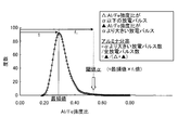
- FIG. 3 is a frequency distribution diagram in which the horizontal axis represents the Al / Fe intensity ratio for each discharge pulse and the vertical axis represents frequency.
- FIG. 4 is a graph showing the correlation between the alumina strength ratio and the chemical analysis value at each f 1 value.
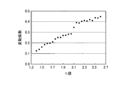
- FIG. 5 is a graph showing the relationship between the alumina strength ratio at each f 1 value and the variation during repeated analysis.
- FIG. 1 is a graph showing the relationship between the rate of occurrence of hydrogen-induced cracking (%) in the HIC resistance test and the amount of CaO / Al 2 O 3 in molten steel.
- FIG. 2 is a conceptual diagram of the Al / Fe intensity ratio when the Al /
- FIG. 6 is a graph showing the correlation between the alumina concentration determined by the alumina quantification method according to the present invention and the chemical analysis value when the f 1 value is 2.0.
- FIG. 7 is a graph showing experimental results comparing hydrogen-induced crack occurrence rates in the HIC resistance test in the examples of the present invention and comparative examples.
- the background to the present invention will be described below.
- the inclusion composition was analyzed for inclusion composition in the range of 100 mm 2 in the slab using particle analysis SEM (scanning electron microscopy).
- particle analysis SEM scanning electron microscopy
- particle analysis SEM which has become popular, can simultaneously acquire information on the composition, size, and number of inclusions.
- the inclusion composition analyzed by particle analysis SEM can be used as an index of HIC resistance in the present invention. Very suitable.
- the amount of CaO in the molten steel can be obtained by subtracting the amount of Ca that has reacted with S in the molten steel from the amount of Ca added using the amount of Ca added in consideration of the Ca yield and the amount of [S] before Ca addition. It can. That is, Ca is the Ca addition amount [kg], y is the Ca yield [%], [S] is the S concentration [mass%] in the steel before Ca addition, and W is the molten steel weight [kg].
- the amount can be determined by the following equation (3).
- the Ca yield y [%] is a ratio of the Ca addition amount in the tundish and may be determined from past data. For example, the Ca yield for a predetermined number of charges immediately before the charge is calculated for each charge, and the average value of a collection of these calculated values for each charge is used as the Ca yield.
- the predetermined number of charges immediately before is preferably 10 charges.
- T.O As a method for knowing the amount of Al 2 O 3 in molten steel, T.O. The method of approximating by the amount of [O] and insol. There is a method for determining the amount of Al. In the present invention, it is preferable to determine the alumina quantitative method described below as an index correlated directly with the amount of Al 2 O 3.
- FIG. 1 is a graphical representation of the results.
- the vertical axis in FIG. 1 represents the hydrogen-induced crack occurrence rate (%) in the HIC resistance test, and the horizontal axis represents the CaO amount / Al 2 O 3 amount represented by the following formula (4).
- ⁇ Alumina determination method> A part of aluminum (hereinafter referred to as Al) added to the molten steel in the steelmaking refining process reacts with oxygen in the steel to form alumina (Al 2 O 3 ) and gradually floats on the surface and is removed from the molten steel. It is. On the other hand, the remaining unreacted Al solidifies while being dissolved in the steel. After the solidification of the steel, alumina that has not been levitated and removed remains in the steel as it is, while unreacted Al is present in the steel mainly as solute Al. Solid solution Al dissolves together when the steel sample is dissolved with an acid, but alumina does not dissolve, so the solid solution Al and alumina are separated from each other by acid dissolution.
- the former is referred to as acid-soluble Al (hereinafter referred to as sol.Al)
- the latter is referred to as acid-insoluble Al (hereinafter referred to as insol.Al).
- spark discharge optical emission spectrometry has been widely used as a rapid analysis method for controlling steel composition, and various approaches have been adopted not only for component analysis but also for quantitative determination of oxide content in steel. Has been made.
- this conventional analysis method it has been difficult to accurately analyze a small amount of alumina in steel at 50 ppm or less.
- the inventors of the present invention calculated the ratio between the emission intensity of Al and the emission intensity of iron for each discharge pulse (the value obtained by dividing the emission intensity of Al by the emission intensity of iron, hereinafter referred to as the Al / Fe intensity ratio). ) was observed over time. As a result, insol. In the sample with a lot of Al, many irregular spikes were confirmed. This spike-like point is insol. It is inferred that it was generated by a discharge containing Al. In spark discharge, the discharge is likely to concentrate on inclusions (insole.Al). The observed Al intensity is sol. Although composed of light from Al and light from inclusions (insole.Al), the ratio of each differs for each discharge pulse.
- FIG. 2 is a conceptual diagram showing the structure of the Al / Fe intensity ratio when the Al / Fe intensity ratios are arranged.
- the vertical axis shows the Al / Fe intensity ratio
- the horizontal axis shows a small Al / Fe intensity ratio.
- the position (%) of each discharge pulse in the array of discharge pulses rearranged in order (ascending order) is shown.
- the side with the larger Al / Fe intensity ratio is insol. Al is dominant and the small side is sol. Al is dominant.
- Al is uniformly present in the ground iron, the sol.
- the Al intensity derived from Al should show a constant value as long as it is a relative value with respect to Fe (Al / Fe intensity ratio). That is, the Al / Fe strength ratio is constant sol. Al intensity ratio and uncertain insol.
- the amount of alumina is quantified by the following procedure. First, the Al / Fe intensity ratio between aluminum and iron by a number of discharge pulses (for example, 2000 times) is determined for each discharge pulse (intensity ratio calculation step).
- the threshold value ⁇ in the above formula (6) is a frequency distribution chart with the horizontal axis representing the Al / Fe intensity ratio for each discharge pulse and the vertical axis representing frequency (frequency). identified as f 1 times the mode of Al / Fe intensity ratio obtained from the histogram.
- the frequency distribution of the emission intensity ratio derived from the solute Al is considered to have the same variation width. From this, it is possible to separate the signal component derived from alumina while keeping the influence degree of solute Al at a constant ratio by setting the value of a constant multiple larger than 1 of the mode value of the Al / Fe intensity ratio as a threshold value. it is conceivable that. Therefore, the number of discharge pulses having an Al / Fe intensity ratio for each discharge pulse greater than f 1 times the mode value is obtained, and the obtained discharge pulse number divided by the total discharge pulse number is defined as the alumina fraction.
- the value of f 1 is in the range of 1.5 to 2.5, more preferably in the range of 1.7 to 2.0. If the value of f 1 is less than 1.5, since the data derived from the solid solution of aluminum is increased, correlation between amount of alumina is deteriorated. On the other hand, when the value of f 1 is larger than 2.5, the number of discharge pulses including the extracted alumina-derived signal becomes too small, and the variation in analysis becomes large.
- FIG. 4 shows the correlation coefficient between the alumina strength ratio and the chemical analysis value at each f 1 value.
- FIG. 5 shows the coefficient of variation at the time of repeated analysis for each f 1 value. As shown in FIG. 4, it can be seen that when f 1 is 1.5 or less, the correlation coefficient between the alumina strength ratio and the chemical analysis value rapidly decreases. This is considered to be due to the influence of light emission derived from solid solution aluminum. Further, as shown in FIG.
- FIG. 6 shows the correlation between the alumina concentration obtained by the alumina quantification method according to the present invention and the chemical analysis value when the f 1 value is 2.0.
- the standard deviation ⁇ d indicating the accuracy of the analysis at this time was 1.8 ppm.
- the Al / Fe intensity ratio for each discharge pulse obtained by the intensity ratio calculation step is arranged in ascending order, and the Al / Fe intensity ratio at a fixed position is made the representative aluminum intensity ratio.
- the representative aluminum intensity ratio means that when the Al / Fe intensity ratio for each discharge pulse is arranged in ascending order (see FIG. 2), any one of 30% or less of the total number of discharge pulses in ascending order of the Al / Fe intensity ratio. It is preferable that the intensity ratio be such a position. The reason for this is that if the position greater than 30% is the representative aluminum strength ratio, the influence of the amount of alumina present in the sample becomes too great, and acid-soluble Al (sol. Al) and alumina are distributed accurately. This is because the analysis accuracy deteriorates without being a representative value for the above.
- the alumina strength ratio is calculated from the product of the alumina fraction obtained in the alumina fraction calculation step and the representative aluminum strength ratio.
- the target amount of alumina (in steel) Is quickly quantified.
- the same Ca-added steel is used for the calibration curve sample, and after setting each necessary coefficient from the Al / Fe intensity ratio obtained by spark discharge optical emission spectrometry for each sample, the calculated alumina strength ratio and true A correlation line with the value is taken as a calibration curve.
- the spark discharge optical emission spectrometer be as close to the production site as possible, and if possible, on-site analysis on the machine side Is most preferred.
- the molten steel component can be controlled to an inclusion composition capable of reducing hydrogen-induced cracking, so the optimum amount of Ca to be added to the molten steel Therefore, it is possible to manufacture a steel material having excellent HIC resistance.
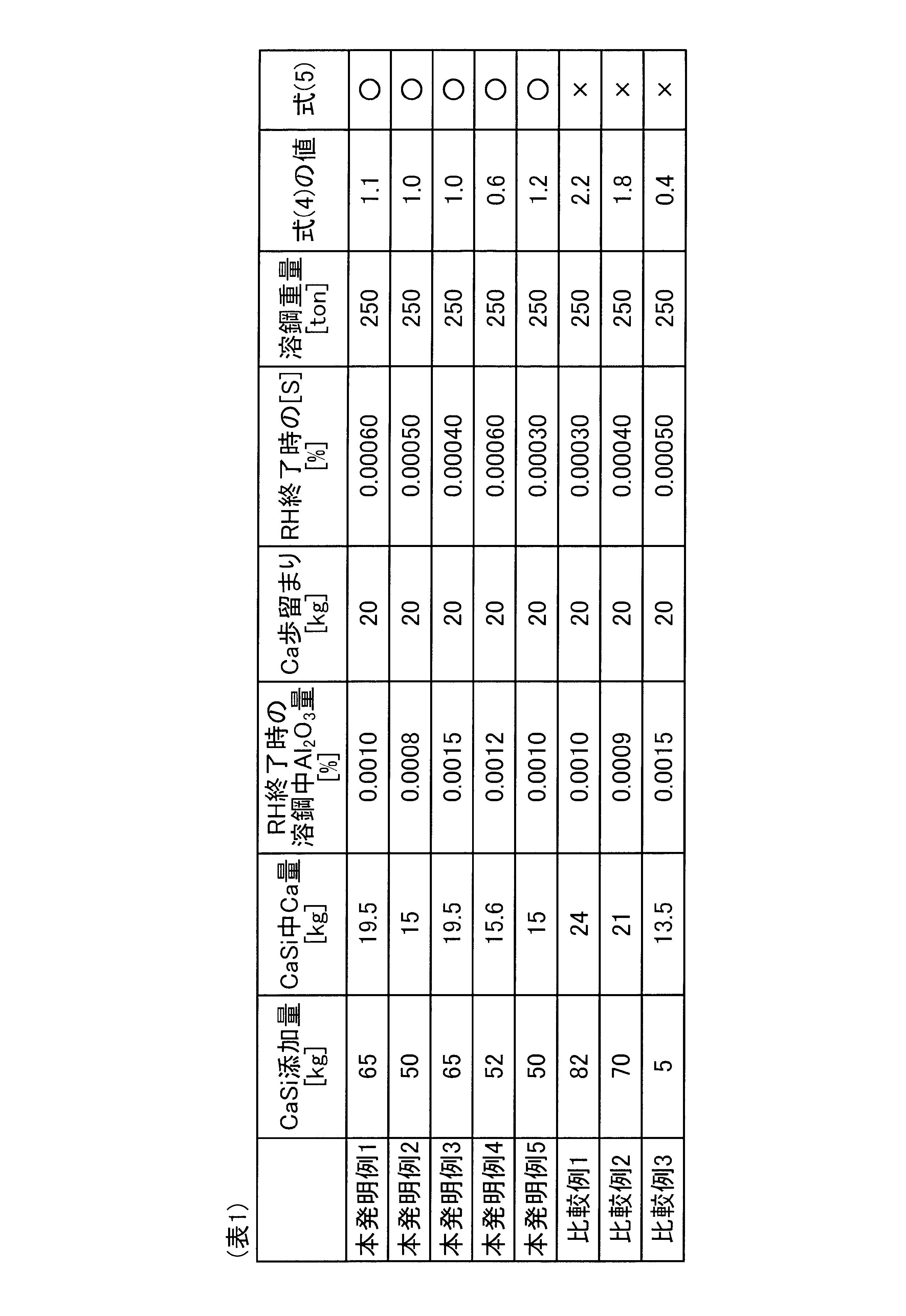
- Ca was quantified by a normal analysis means, and the amount of Al 2 O 3 was calculated by the alumina quantification method described above.
- the same Ca addition steel was used for the calibration curve sample. After setting each necessary coefficient from the Al / Fe intensity ratio obtained by spark discharge optical emission spectrometry for each sample in advance, the correlation line between the calculated alumina intensity ratio and the amount of alumina obtained from the chemical analysis method is calibrated. A line.
- FIG. 7 shows the hydrogen-induced crack occurrence rate.
- the rate of occurrence of hydrogen-induced cracking in the HIC test was 6.5% or more, whereas in the present invention example, it was 1.5% or less.
- the present invention can be applied to a process of manufacturing a steel material having excellent HIC resistance by adding Ca to molten steel accommodated in a container to adjust the components of the molten steel.
Landscapes
- Chemical & Material Sciences (AREA)
- Engineering & Computer Science (AREA)
- Materials Engineering (AREA)
- Metallurgy (AREA)
- Organic Chemistry (AREA)
- Health & Medical Sciences (AREA)
- Mechanical Engineering (AREA)
- Physics & Mathematics (AREA)
- Nuclear Medicine, Radiotherapy & Molecular Imaging (AREA)
- Life Sciences & Earth Sciences (AREA)
- Analytical Chemistry (AREA)
- Biochemistry (AREA)
- General Health & Medical Sciences (AREA)
- General Physics & Mathematics (AREA)
- Immunology (AREA)
- Pathology (AREA)
- Treatment Of Steel In Its Molten State (AREA)
- Investigating, Analyzing Materials By Fluorescence Or Luminescence (AREA)
- Investigating And Analyzing Materials By Characteristic Methods (AREA)
Abstract
Description


製鋼精錬工程で溶鋼に添加されたアルミニウム(以下、Alと称す)は、その一部は鋼中の酸素と反応しアルミナ(Al2O3)となって徐々に表面に浮上して溶鋼から取り除かれる。一方、残りの未反応のAlは鋼中に溶解したまま凝固する。鋼の凝固後、浮上除去されなかったアルミナはそのままの状態で鋼中に残る一方、未反応のAlは主として固溶Alとして鋼中に存在する。固溶Alは鋼試料が酸で溶解する際に一緒に溶解するが、アルミナは溶解しないので、固溶Alとアルミナとは酸溶解により互いに分離される。前者は酸可溶性Al(以下、sol.Alと称す)と呼ばれ、後者は酸不溶性Al(以下、insol.Alと称す)と呼ばれる。

以下に説明する実施例により、本発明の効果が確認された。
Claims (3)
- 下記式(1)を満たす範囲にCa量を調整して溶鋼に添加するステップを含むことを特徴とする鋼材の製造方法。

- 二次精錬後に、溶鋼中のAl2O3量を分析し、その後CaSiを取鍋内の溶鋼中に添加するステップを含むことを特徴とする請求項1に記載の鋼材の製造方法。
- 溶鋼中のAl2O3量の分析をスパーク放電発光分光分析法を用いて行う鋼材の製造方法であって、
多数回の放電パルスによるアルミニウムと鉄との発光強度比を放電パルス毎に求める強度比計算ステップと、
下記式(2)にて求められるアルミナ分率を算出するアルミナ分率算出ステップと、
前記強度比計算ステップにより得られた放電パルス毎の前記発光強度比を小さい順に配列し、小さい順に全放電パルス数の30%以内の一定位置の前記発光強度比を代表アルミ強度比とし、次いで、前記アルミナ分率算出ステップで算出されたアルミナ分率と代表アルミ強度比との積からアルミナ強度比(=アルミナ分率×代表アルミ強度比)を算出するステップと、
前記アルミナ強度比と化学分析により求められた(鋼中)アルミナ量の関係式を用いて(鋼中)アルミナ量を算出する定量ステップと、
を含むことを特徴とする請求項1または2に記載の鋼材の製造方法。

Priority Applications (6)
| Application Number | Priority Date | Filing Date | Title |
|---|---|---|---|
| BR112015009622-0A BR112015009622B1 (pt) | 2013-07-10 | 2014-06-04 | método para a produção de material de aço |
| EP14822459.5A EP3020833B1 (en) | 2013-07-10 | 2014-06-04 | Method for producing steel material |
| CN201480038899.4A CN105378118A (zh) | 2013-07-10 | 2014-06-04 | 钢材的制造方法 |
| US14/903,103 US10072320B2 (en) | 2013-07-10 | 2014-06-04 | Method of producing steel material |
| KR1020157035763A KR101797839B1 (ko) | 2013-07-10 | 2014-06-04 | 강재의 제조 방법 |
| JP2015526210A JP6037014B2 (ja) | 2013-07-10 | 2014-06-04 | 鋼材の製造方法 |
Applications Claiming Priority (2)
| Application Number | Priority Date | Filing Date | Title |
|---|---|---|---|
| JP2013144370 | 2013-07-10 | ||
| JP2013-144370 | 2013-07-10 |
Publications (1)
| Publication Number | Publication Date |
|---|---|
| WO2015005023A1 true WO2015005023A1 (ja) | 2015-01-15 |
Family
ID=52279716
Family Applications (1)
| Application Number | Title | Priority Date | Filing Date |
|---|---|---|---|
| PCT/JP2014/064812 Ceased WO2015005023A1 (ja) | 2013-07-10 | 2014-06-04 | 鋼材の製造方法 |
Country Status (8)
| Country | Link |
|---|---|
| US (1) | US10072320B2 (ja) |
| EP (1) | EP3020833B1 (ja) |
| JP (1) | JP6037014B2 (ja) |
| KR (1) | KR101797839B1 (ja) |
| CN (1) | CN105378118A (ja) |
| BR (1) | BR112015009622B1 (ja) |
| TW (1) | TWI585209B (ja) |
| WO (1) | WO2015005023A1 (ja) |
Cited By (2)
| Publication number | Priority date | Publication date | Assignee | Title |
|---|---|---|---|---|
| JP2020509197A (ja) * | 2016-12-23 | 2020-03-26 | ポスコPosco | 耐水素誘起割れ性に優れた圧力容器用鋼材及びその製造方法 |
| JP7093090B1 (ja) | 2021-06-22 | 2022-06-29 | 燕山大学 | ディープニューラルネットワークに基づくカルシウム処理工程におけるカルシウムの収得率の予測方法 |
Families Citing this family (1)
| Publication number | Priority date | Publication date | Assignee | Title |
|---|---|---|---|---|
| EP3726206B1 (en) * | 2019-03-26 | 2022-11-02 | FEI Company | Methods and systems for inclusion analysis |
Citations (3)
| Publication number | Priority date | Publication date | Assignee | Title |
|---|---|---|---|---|
| JPH0199761A (ja) * | 1987-10-13 | 1989-04-18 | Kawasaki Steel Corp | アルミキルド鋼の連続鋳造方法 |
| JP2001214237A (ja) * | 1999-11-22 | 2001-08-07 | Sumitomo Metal Ind Ltd | アルミキルド鋼 |
| JP2011089180A (ja) | 2009-10-23 | 2011-05-06 | Sumitomo Metal Ind Ltd | 高強度・高耐食性油井管用鋼材の溶製方法 |
Family Cites Families (12)
| Publication number | Priority date | Publication date | Assignee | Title |
|---|---|---|---|---|
| JP2999671B2 (ja) | 1994-06-14 | 2000-01-17 | 川崎製鉄株式会社 | Ca添加鋼の溶製方法 |
| JP3362511B2 (ja) | 1994-07-14 | 2003-01-07 | 日本鋼管株式会社 | 鋼中アルミナの迅速分析方法 |
| JPH0853707A (ja) | 1994-08-11 | 1996-02-27 | Sumitomo Metal Ind Ltd | 耐hic鋼の製造方法 |
| JPH08333619A (ja) | 1995-06-06 | 1996-12-17 | Kawasaki Steel Corp | 耐水素誘起割れ性に優れた鋼の製造方法 |
| JPH101124A (ja) | 1996-06-12 | 1998-01-06 | Fuji Seal Co Ltd | 筒状ストレッチラベル |
| JPH10121124A (ja) | 1996-10-21 | 1998-05-12 | Nippon Steel Corp | ノズル閉塞を防止する溶湯及び材料とその製造方法 |
| JP3807377B2 (ja) | 2003-02-07 | 2006-08-09 | 住友金属工業株式会社 | 低Al溶鋼のCa処理方法 |
| JP4180971B2 (ja) | 2003-05-19 | 2008-11-12 | 株式会社神戸製鋼所 | ビレット連鋳におけるCaの添加方法 |
| JP4135691B2 (ja) | 2004-07-20 | 2008-08-20 | 住友金属工業株式会社 | 窒化物系介在物形態制御鋼 |
| CN101565771B (zh) | 2009-04-29 | 2011-01-19 | 天津钢管集团股份有限公司 | 炼钢钢液的钙处理方法 |
| JP2011214237A (ja) * | 2010-03-31 | 2011-10-27 | Sanwa Shutter Corp | 建築用の重量シャッター装置におけるシャッターケース |
| JP5454403B2 (ja) | 2010-07-20 | 2014-03-26 | Jfeスチール株式会社 | 鉄鋼中のsol.Alの高精度定量方法および鉄鋼中のsol.Alの高精度定量方法の工程運用方法 |
-
2014
- 2014-06-04 EP EP14822459.5A patent/EP3020833B1/en active Active
- 2014-06-04 WO PCT/JP2014/064812 patent/WO2015005023A1/ja not_active Ceased
- 2014-06-04 US US14/903,103 patent/US10072320B2/en active Active
- 2014-06-04 JP JP2015526210A patent/JP6037014B2/ja active Active
- 2014-06-04 BR BR112015009622-0A patent/BR112015009622B1/pt active IP Right Grant
- 2014-06-04 KR KR1020157035763A patent/KR101797839B1/ko active Active
- 2014-06-04 CN CN201480038899.4A patent/CN105378118A/zh active Pending
- 2014-07-09 TW TW103123545A patent/TWI585209B/zh active
Patent Citations (3)
| Publication number | Priority date | Publication date | Assignee | Title |
|---|---|---|---|---|
| JPH0199761A (ja) * | 1987-10-13 | 1989-04-18 | Kawasaki Steel Corp | アルミキルド鋼の連続鋳造方法 |
| JP2001214237A (ja) * | 1999-11-22 | 2001-08-07 | Sumitomo Metal Ind Ltd | アルミキルド鋼 |
| JP2011089180A (ja) | 2009-10-23 | 2011-05-06 | Sumitomo Metal Ind Ltd | 高強度・高耐食性油井管用鋼材の溶製方法 |
Cited By (4)
| Publication number | Priority date | Publication date | Assignee | Title |
|---|---|---|---|---|
| JP2020509197A (ja) * | 2016-12-23 | 2020-03-26 | ポスコPosco | 耐水素誘起割れ性に優れた圧力容器用鋼材及びその製造方法 |
| US11578376B2 (en) | 2016-12-23 | 2023-02-14 | Posco Co., Ltd | Steel for pressure vessels having excellent resistance to hydrogen induced cracking and manufacturing method thereof |
| JP7093090B1 (ja) | 2021-06-22 | 2022-06-29 | 燕山大学 | ディープニューラルネットワークに基づくカルシウム処理工程におけるカルシウムの収得率の予測方法 |
| JP2023002457A (ja) * | 2021-06-22 | 2023-01-10 | 燕山大学 | ディープニューラルネットワークに基づくカルシウム処理工程におけるカルシウムの収得率の予測方法 |
Also Published As
| Publication number | Publication date |
|---|---|
| TW201504443A (zh) | 2015-02-01 |
| JP6037014B2 (ja) | 2016-11-30 |
| US10072320B2 (en) | 2018-09-11 |
| CN105378118A (zh) | 2016-03-02 |
| EP3020833A1 (en) | 2016-05-18 |
| US20160145718A1 (en) | 2016-05-26 |
| BR112015009622B1 (pt) | 2020-12-01 |
| EP3020833B1 (en) | 2018-04-11 |
| KR101797839B1 (ko) | 2017-11-15 |
| TWI585209B (zh) | 2017-06-01 |
| KR20160008640A (ko) | 2016-01-22 |
| JPWO2015005023A1 (ja) | 2017-03-02 |
| BR112015009622A2 (pt) | 2017-07-04 |
| EP3020833A4 (en) | 2017-03-22 |
Similar Documents
| Publication | Publication Date | Title |
|---|---|---|
| JP5974962B2 (ja) | 耐HIC特性に優れたCaを添加したアルミキルド鋼材の製造方法及び溶鋼のCa添加処理方法 | |
| JP6037014B2 (ja) | 鋼材の製造方法 | |
| JP2014173892A (ja) | スラブにおける異なる板厚位置でのCa濃度分析結果を用いた耐サワー鋼スラブの品質判定方法 | |
| JP5978967B2 (ja) | 溶鋼の成分調整方法 | |
| JP5884182B2 (ja) | Ca含有アルミキルド鋼の介在物組成の制御方法 | |
| JP2013145221A (ja) | Hic割れ危険度が低い鋼材及びその中心偏析部評価法 | |
| CN107449769A (zh) | Icp‑aes法测定钇镁合金中杂质元素的方法 | |
| JP5454403B2 (ja) | 鉄鋼中のsol.Alの高精度定量方法および鉄鋼中のsol.Alの高精度定量方法の工程運用方法 | |
| US4592655A (en) | Method of determining elements in metals by means of optical emission spectrum analysis | |
| JP5998801B2 (ja) | 鉄鋼中のアルミナ定量分析方法 | |
| JP2008266751A (ja) | 溶鋼の精錬方法 | |
| JP2015058473A (ja) | 耐サワーラインパイプ鋼スラブの品質判定による向け先変更方法 | |
| JP4289214B2 (ja) | 溶鋼の脱炭処理方法および溶鋼製造方法 | |
| JP6052248B2 (ja) | カルシウム添加鋼の製造方法 | |
| EP2743683B1 (en) | Molten iron desulfurization method | |
| JP2015083713A (ja) | 耐水素誘起割れ特性に優れた鋼材及びその製造方法 | |
| JP4345213B2 (ja) | 高Si含有溶鋼のAl濃度調整方法 | |
| JP7636672B2 (ja) | 鋼材の耐水素誘起割れ性の評価方法 | |
| JP7775774B2 (ja) | 金属材料中Sbの発光分光分析法、精錬中溶鋼のSb濃度測定方法および鋼素材の製造方法 | |
| CN111157482B (zh) | 一种铝钙系脱氧剂中氧含量的检测方法 | |
| JP3807377B2 (ja) | 低Al溶鋼のCa処理方法 | |
| JP2015205338A (ja) | 耐hic特性に優れた鋼材の製造方法 | |
| JP2006283089A (ja) | 電磁鋼製造におけるAl添加方法 | |
| JP2003268438A (ja) | 溶鋼の精錬方法 | |
| Jenkins et al. | Sampling and analysis for an oxygen steel shop |
Legal Events
| Date | Code | Title | Description |
|---|---|---|---|
| 121 | Ep: the epo has been informed by wipo that ep was designated in this application |
Ref document number: 14822459 Country of ref document: EP Kind code of ref document: A1 |
|
| REG | Reference to national code |
Ref country code: BR Ref legal event code: B01A Ref document number: 112015009622 Country of ref document: BR |
|
| ENP | Entry into the national phase |
Ref document number: 2015526210 Country of ref document: JP Kind code of ref document: A |
|
| WWE | Wipo information: entry into national phase |
Ref document number: 2014822459 Country of ref document: EP |
|
| ENP | Entry into the national phase |
Ref document number: 20157035763 Country of ref document: KR Kind code of ref document: A |
|
| WWE | Wipo information: entry into national phase |
Ref document number: 14903103 Country of ref document: US |
|
| NENP | Non-entry into the national phase |
Ref country code: DE |
|
| ENP | Entry into the national phase |
Ref document number: 112015009622 Country of ref document: BR Kind code of ref document: A2 Effective date: 20150429 |