WO2015010251A1 - Appareil d'évacuation de liquide présentant une forme réglable - Google Patents
Appareil d'évacuation de liquide présentant une forme réglable Download PDFInfo
- Publication number
- WO2015010251A1 WO2015010251A1 PCT/CN2013/079904 CN2013079904W WO2015010251A1 WO 2015010251 A1 WO2015010251 A1 WO 2015010251A1 CN 2013079904 W CN2013079904 W CN 2013079904W WO 2015010251 A1 WO2015010251 A1 WO 2015010251A1
- Authority
- WO
- WIPO (PCT)
- Prior art keywords
- adjacent
- liquid discharge
- hollow shaft
- shape
- discharge device
- Prior art date
- Legal status (The legal status is an assumption and is not a legal conclusion. Google has not performed a legal analysis and makes no representation as to the accuracy of the status listed.)
- Ceased
Links
Images




Classifications
-
- E—FIXED CONSTRUCTIONS
- E03—WATER SUPPLY; SEWERAGE
- E03C—DOMESTIC PLUMBING INSTALLATIONS FOR FRESH WATER OR WASTE WATER; SINKS
- E03C1/00—Domestic plumbing installations for fresh water or waste water; Sinks
- E03C1/02—Plumbing installations for fresh water
- E03C1/04—Water-basin installations specially adapted to wash-basins or baths
- E03C1/0403—Connecting the supply lines to the tap body
-
- E—FIXED CONSTRUCTIONS
- E03—WATER SUPPLY; SEWERAGE
- E03C—DOMESTIC PLUMBING INSTALLATIONS FOR FRESH WATER OR WASTE WATER; SINKS
- E03C1/00—Domestic plumbing installations for fresh water or waste water; Sinks
- E03C1/02—Plumbing installations for fresh water
- E03C1/04—Water-basin installations specially adapted to wash-basins or baths
- E03C2001/0414—Water-basin installations specially adapted to wash-basins or baths allowing different orientations of the spout or the outlet nozzle
-
- E—FIXED CONSTRUCTIONS
- E03—WATER SUPPLY; SEWERAGE
- E03C—DOMESTIC PLUMBING INSTALLATIONS FOR FRESH WATER OR WASTE WATER; SINKS
- E03C1/00—Domestic plumbing installations for fresh water or waste water; Sinks
- E03C1/02—Plumbing installations for fresh water
- E03C1/04—Water-basin installations specially adapted to wash-basins or baths
- E03C2001/0417—Water-basin installations specially adapted to wash-basins or baths having space-saving features, e.g. retractable, demountable
Definitions
- the present invention relates to the field of liquid pipeline technology, and more particularly to a shape-adjustable liquid discharge device.
- Faucets and faucets are a common device used in modern kitchen and bathroom renovations. At present, most common faucets are integrated and cannot be twisted or folded. However, since the main body of the faucet tube tends to be long, after the faucet or the faucet tube is fixedly installed, it restricts the available space above the pool, which brings inconvenience to people's lives.
- a folded faucet has been proposed in the industry. See a Chinese patent with the announcement number CN202195133U, as shown in Fig. 1, which includes a faucet tube 01, a valve handle 02 and a sleeve holder 03, the sleeve holder 03 One end is mounted with a rotating device 04, the faucet tube 01 is mounted at the upper end of the rotating device 04, and the rotating device 04 and the valve handle 02 are mounted at both ends of the socket seat 03, the rotating device 04 including a horizontal shaft sleeve and a vertical bushing Tube; realizes the left and right rotation of the faucet and folds down.
- the patent solves the problem that the faucet folds and retracts when the faucet is not in use, and releases the space above the pool; however, the faucet tube itself cannot be folded, and the release space is limited; at the same time, the entire rotating device is composed of a horizontal sleeve and a vertical sleeve. Part of the composition, the structure is relatively complex. In addition, the exposed design of the rotating device is extremely poor in appearance, and it is difficult to meet the simple design pursued by modern people, and it is not easy to be recognized by consumers.
- an object of the present invention is to provide a liquid discharge device which can be completely folded, has a hidden joint, is easy to connect, and can be freely deformed.
- the present invention adopts the following technical solutions.
- a shape-adjustable liquid discharge device wherein at least one portion of the liquid flowing through the pipe is a movable member, characterized in that each movable member and its adjacent members are connected and electrically connected by a hollow shaft, and the axis of the hollow shaft is The normal section normals of two adjacent components are not parallel.
- each of the movable members and their adjacent members are connected and electrically connected by a common hollow shaft, and the connection structure is simple; as an equivalent option, the hollow shafts are two which are movably engaged with each other.
- the connecting faces of the movable parts and their adjacent parts are not parallel to the respective positive sections, the hollow axes are perpendicular to the connecting faces, and are hidden in each movable part and its adjacent parts; In order to avoid the appearance of the hollow shaft exposed.
- At least one sealing ring is provided on the hollow shaft, the hollow shaft being sealingly connected to two adjacent components.
- the hollow shaft is fixedly connected to one of the two adjacent components and is movably connected to the other.
- the hollow shaft is movably connected to two adjacent components.
- the movable connection means that one of the components is provided with a stepped position on the end, and the outer wall of the hollow shaft is provided with a blocking ring and a sealing ring; when installed, the sealing ring and the inner wall of the component In close contact, one side of the blocking ring is in the step position and the other side is defined by a flap fixed to the part.
- the connecting ends of the two adjacent components are respectively provided with a connecting head, and the connecting head is provided with a water passing hole which is electrically connected to two adjacent components, and the step position is formed at Around the water hole, the hollow shaft and the sealing ring are inserted in the water passing hole.
- the positive cross section of the liquid flowing through the pipe is an axisymmetric pattern such as a circle, an ellipse, a rectangle, a diamond, or the like.
- the connecting faces of the movable member and its adjacent members are two planes parallel to each other, and the connecting planes of the adjacent two members are equal to the angles of the respective normal portions of the normal sections. In this way, the movable part and its adjacent parts can be on the same line after being rotated.
- the movable part and its adjacent parts are straight strip-shaped parts, and the connecting planes of the two adjacent parts are at an angle of 45° with the normal lines of the respective normal sections, which facilitates the realization of the movable parts and their adjacent parts.
- At least one of the movable member and its adjacent members is a curved member, and the angle ⁇ C of the curved member and the angle ⁇ B between the connecting plane and the normal of the normal section satisfy the relationship:
- it is used on a faucet outlet, a shower outlet or a discharge tube of a beverage machine.
- the present invention provides a shape-adjustable liquid discharge device having the following beneficial effects:
- each movable part and its adjacent parts are connected and connected by a common hollow shaft, and the axis of the hollow shaft and the positive cross section method of the adjacent two parts
- the lines are not parallel; in this way, the rotation of the moving parts can be realized, and the adjustment of the height and the lateral extension length of the liquid flowing through the pipeline can be realized, or the liquid can be folded through the pipeline, and the liquid can be controlled to flow through the pipeline.
- the space occupied by the time, the adjustment method is simple, free and free.
- the presence of the hollow shaft avoids the built-in or external bent tube, and the liquid can be transferred through the pipe whether the moving part is rotating or not rotating.
- step position on one of the adjacent members, and providing a blocking ring and a sealing ring on the outer wall of the hollow shaft; when installing, the sealing ring is in close contact with the inner wall of the member, and one side of the blocking ring is blocked in the step position.
- the other side is defined by a baffle fixed on the component, which not only realizes 360° free circulation rotation between adjacent moving parts, but also avoids leakage of liquid, and has good practicability.
- the separate processing of the step position is facilitated by providing a connector having a water hole on the connection end of the adjacent two components and molding the step on the connector.
- the connecting faces of the movable part and its adjacent parts are inclined with respect to the respective positive sections; when installing, by turning the adjacent two parts by an angle, It is convenient to realize the connection between the hollow shaft and the moving parts and their adjacent parts, and the installation is convenient.
- the connecting surface of the moving part and its adjacent parts is a plane
- the connecting planes of the two adjacent parts are equal to the angles of the normal lines of the respective normal sections, so that the moving parts can be in the same line with their adjacent parts after being rotated. .
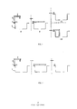
- Figure 1 is a schematic view showing the structure of a conventional folding faucet
- FIG. 2 is a schematic structural view of a first embodiment of a liquid discharging device provided by the present invention
- Figure 3 is a schematic view showing the connection structure of two adjacent movable parts in the first embodiment
- FIG. 4 is a schematic view showing a folding manner of the first embodiment of the liquid discharging device provided by the present invention.
- Figure 5 is a schematic view showing the folding mode of the second embodiment of the liquid discharging device provided by the present invention.
- Figure 6 is a schematic structural view showing the third embodiment of the liquid discharging device provided by the present invention.
- Figure 7 is a schematic view showing the folding mode of the third embodiment of the liquid discharging device provided by the present invention.
- FIG. 8 is a schematic view showing the folding manner of the fourth embodiment of the liquid discharging device provided by the present invention.
- a shape-adjustable liquid discharge device the liquid flowing through the pipe includes: a first movable part 1, a second movable part 2 and a third movable part 3 connected together, wherein The first movable member 1 and the second movable member 2 and the second movable member 2 and the third movable member 3 are bendable with each other. Adjacent members that are bent toward each other are connected and electrically connected by a common hollow shaft 7, and the axis of the hollow shaft 7 is not parallel to the normal of the normal section of the adjacent two members. In this way, the adjacent two movable parts can realize the deformation of the liquid flowing through the pipe only by rotating, and the shape adjustment is simple.
- the hollow shaft is two sleeved sleeves, each hollow shaft is fixed to an adjacent member bent to each other, and rotation between the two movable members is realized by rotation between the hollow shafts, thereby achieving
- the purpose of the liquid flowing through the pipe is not limited to this embodiment.
- the connecting faces of the movable parts are not parallel to the respective positive sections, the hollow shaft 7 is perpendicular to the connecting face, serves as a rotating shaft of the movable part, and is hidden in each movable part and its adjacent parts; Avoid the exposure of the rotating joints, ensuring the integrity and aesthetics of the entire liquid flowing through the pipe.
- the first folding member 1 is vertically mounted on the side of the water tank 4, and the distance from the top plane of the water tank 4 is not more than 5 cm; the length of the second movable member 2 and the third movable member 3 is larger than that of the first movable member 1. length.
- the first, second, and third movable members 1, 2, and 3 are all circular faucet tubes, and preferably the first movable member 1 protrudes from the top plane of the water tank 4 by 3 cm. In this way, after the liquid of the entire liquid discharge device is folded through the pipe, it is only 3 cm away from the surface of the water tank, and the kitchen space can be released to the utmost extent.
- the arrangement of the second movable part 2 here mainly serves to extend the vertical height of the liquid discharge pipe
- the arrangement of the third movable part 3 here mainly serves to extend the horizontal coverage surface of the liquid discharge pipe.
- the water tank is omitted, and the first, second, and third movable members are mounted to the shower water outlet port or the beverage machine outlet interface, and are not limited to the embodiment.
- the connecting ends of the two movable members which are bent to each other are provided with the first connecting head 5 and the second connecting head 6 which cooperate with each other.
- the first joint 5 is welded to the top of the second movable member 2, and the second joint 6 is welded to one end of the third movable member 3.
- the first connecting head 5 and the second connecting head 6 are respectively provided with water passing holes 51, 61 communicating with the second movable part 2 and the third movable part 3, and the hollow shaft 7 is inserted in the water passing holes 51, 61.
- the connection and conduction between the second movable part 2 and the third movable part 3 are realized.
- the first connector and the second connector are integrally formed on the second movable member and the third movable member, and are not limited to the embodiment.
- the hollow shaft 7 is welded to the first joint 5 and movably connected to the second joint 6; and the hollow shaft 7 is connected to the second At least one sealing ring 10 is disposed between the heads 6.
- the number of the sealing rings is two.
- the movable connection means that a step position is arranged on the second connecting head 6, and a blocking ring 71 is fixed on the outer wall of the hollow shaft 7; when installed, one side of the blocking ring 71 is blocked on the step position, The other side is defined by a flap 9 which is fixed to the second connector 6 by a screw 8.
- the blocking ring 71 is free to rotate in a defined space formed by the stepped portion and the flap 9, thereby achieving 360° rotation between the joint head 6 and the hollow shaft 7.
- the hollow shaft is movably connected to both the first connector 5 and the second connector 6, and is not limited to the embodiment.
- the shape-adjustable liquid discharge device has a first movable part 1 mounted on the left side of the water tank 4 through the rotary head 11, and a first part is formed on the top of the first movable part 1.
- a movable member has a connecting surface of a 45° angle in a normal cross section, and one end of the second movable member 2 is connected to the top of the first movable member 1, and the other end thereof forms a connecting surface at an angle of -45° to the cross section of the second movable member. Used to connect the third movable part 3.
- the third movable part 3 is first rotated in a straight line with the second movable part 2 by 180 degrees, and then the first movable part 1 is rotated by 180 degrees around the rotating head, and the second movable part 2 is opposite.
- the inclined surface of the first movable member 1 is rotated by 180 degrees to become the state shown by B in Fig. 4 .
- the height of the entire liquid discharge device flowing through the pipe protruding from the water tank is only the height of the first movable member 1, and the release space is large.
- the first movable part 1 can be rotated 90 degrees around the rotary head to release the water tank space, as shown by C1 in Fig. 4, and it is convenient to use the water tank for washing vegetables, etc., and has good practicability. . If the third movable part 3 is rotated 180 degrees completely without using the water tank, the third movable part can be stored in the water tank, as shown by C2 in Fig. 4, and the liquid of the liquid discharging device is prevented from flowing through the pipeline. More horizontal space.
- the embodiment provides a shape-adjustable liquid discharging device, wherein the liquid flowing through the pipe adopts a plurality of movable parts, and the moving parts connecting faces which are bent together are arranged not to be parallel with the respective positive sections, so that only the passage is required
- the liquid can be adjusted through the pipeline in the height and the lateral extension length, and the folding and folding are achieved.
- the implementation is simple, and the adjustment is free.
- the hollow shaft is hidden in the moving parts and their adjacent parts bent together, the exposure of the rotating joint is avoided, and the integrity and the appearance of the entire liquid discharge pipe are ensured.
- one end of the hollow shaft is welded to the joint, and the other end is movably connected with the adjacent joint.
- the hollow shaft acting as the shaft does not twist or rotate, which effectively ensures the service life of the hollow shaft (rotary joint).
- 360° free-circulation rotation between the movable part and its adjacent parts is achieved by providing a blocking ring on the outer wall of the hollow shaft and fitting the blocking ring in a space formed by the step position of the joint head and the flap. Good sex.
- a shape-adjustable liquid discharge device the liquid flowing through the pipe includes: a first movable part 1, a second movable part 2 and a third movable part 3 connected together, wherein The movable member 1 and the second movable member 2 and the second movable member 2 and the third movable member 3 are bendable to each other. Adjacent members that are bent together are connected and conducted by a common hollow shaft whose axis is not parallel to the normal of the normal section of the adjacent two members.
- the embodiment of the present invention provides a shape-adjustable liquid discharge device having a structure substantially identical to that of the first embodiment, except that a top portion of the first movable member 1 is formed at an angle of -45 to the front cross section of the first movable member.
- the connecting surface is such that the liquid flowing through the pipe is collected on the side of the water tank 4 after being folded.
- a shape-adjustable liquid discharge device the liquid flowing through the pipe includes: a first movable part 1, a second movable part 2 and a third movable part 3 connected together, wherein The first movable member 1 and the second movable member 2 and the second movable member 2 and the third movable member 3 are bendable with each other. Adjacent members that are bent together are connected and conducted by a common hollow shaft whose axis is not parallel to the normal of the normal section of the adjacent two members.
- the embodiment of the present invention provides a shape-adjustable liquid discharge device, and the structure thereof is basically the same as that of the second embodiment. The difference is:
- the connecting surface between the first movable part 1 and the second movable part 2 and between the second movable part 2 and the third movable part 3 are two planes parallel to each other, and the connecting planes of the adjacent two moving parts are respectively positive
- ⁇ A, ⁇ B Both are 45°, 75°, or any other angle between 45° and 90° to adjust the angle at which the third movable member is raised, and are not limited to the embodiment.
- a shape-adjustable liquid discharge device the liquid flowing through the pipe includes: a first movable part 1, a second movable part 2 and a third movable part 3 connected together, wherein The movable member 1 and the second movable member 2 and the second movable member 2 and the third movable member 3 are bendable to each other. Adjacent members that are bent together are connected and conducted by a common hollow shaft whose axis is not parallel to the normal of the normal section of the adjacent two members.
- the embodiment of the present invention provides a shape-adjustable liquid discharge device having a structure substantially identical to that of the third embodiment, except that the second movable member 2 is a curved member having a 90° connection with the third movable member 3.
- the angle of the joint is at an angle of 45° to the normal of the respective normal section.
Landscapes
- Health & Medical Sciences (AREA)
- Life Sciences & Earth Sciences (AREA)
- Engineering & Computer Science (AREA)
- Hydrology & Water Resources (AREA)
- Public Health (AREA)
- Water Supply & Treatment (AREA)
- Domestic Plumbing Installations (AREA)
Abstract
L'invention concerne un appareil d'évacuation de liquide présentant une forme réglable. Au moins une partie des pipelines dans lesquels un liquide s'écoule est composée d'un élément mobile (1, 2, 3), chaque élément mobile (1, 2, 3) et un élément adjacent étant raccordés l'un à l'autre et en communication l'un avec l'autre par un arbre creux (7), et un axe de l'arbre creux (7) n'est pas parallèle à la perpendiculaire de section droite des deux éléments adjacents. L'arbre creux (7) est perpendiculaire à une surface de raccordement et est caché dans chaque élément mobile (1, 2, 3) et l'élément adjacent; cela permet d'empêcher qu'un joint tournant ne soit exposé.
Priority Applications (1)
| Application Number | Priority Date | Filing Date | Title |
|---|---|---|---|
| PCT/CN2013/079904 WO2015010251A1 (fr) | 2013-07-23 | 2013-07-23 | Appareil d'évacuation de liquide présentant une forme réglable |
Applications Claiming Priority (1)
| Application Number | Priority Date | Filing Date | Title |
|---|---|---|---|
| PCT/CN2013/079904 WO2015010251A1 (fr) | 2013-07-23 | 2013-07-23 | Appareil d'évacuation de liquide présentant une forme réglable |
Publications (1)
| Publication Number | Publication Date |
|---|---|
| WO2015010251A1 true WO2015010251A1 (fr) | 2015-01-29 |
Family
ID=52392572
Family Applications (1)
| Application Number | Title | Priority Date | Filing Date |
|---|---|---|---|
| PCT/CN2013/079904 Ceased WO2015010251A1 (fr) | 2013-07-23 | 2013-07-23 | Appareil d'évacuation de liquide présentant une forme réglable |
Country Status (1)
| Country | Link |
|---|---|
| WO (1) | WO2015010251A1 (fr) |
Cited By (11)
| Publication number | Priority date | Publication date | Assignee | Title |
|---|---|---|---|---|
| EP3708721A1 (fr) * | 2019-03-11 | 2020-09-16 | Oras Oy | Robinetterie sanitaire pour distribuer de l'eau |
| IT201900024310A1 (it) * | 2019-12-17 | 2021-06-17 | Vizio Gmbh | Dispositivo di erogazione |
| US11242675B2 (en) * | 2018-06-04 | 2022-02-08 | Kohler Co. | Articulating faucet |
| CN114176417A (zh) * | 2021-11-18 | 2022-03-15 | 中国计量大学上虞高等研究院有限公司 | 一种自动化糕点机及控制方法 |
| US20220081884A1 (en) | 2019-12-19 | 2022-03-17 | Emerson Electric Co. | Configurable Faucet Apparatus and Methods of Implementing and Operating Same |
| US11408543B2 (en) | 2018-02-28 | 2022-08-09 | Kohler Co. | Articulating faucet |
| USD988474S1 (en) * | 2020-10-01 | 2023-06-06 | InSinkErator LLC | Faucet apparatus |
| USD988475S1 (en) | 2020-10-01 | 2023-06-06 | InSinkErator LLC | Faucet apparatus |
| US11703156B2 (en) | 2018-02-28 | 2023-07-18 | Kohler Co. | Articulating faucet with progressive magnetic joint |
| US11913574B2 (en) | 2018-02-28 | 2024-02-27 | Kohler Co. | Magnetic joint |
| US12054925B2 (en) | 2018-06-04 | 2024-08-06 | Kohler Co. | Articulating faucet |
Citations (4)
| Publication number | Priority date | Publication date | Assignee | Title |
|---|---|---|---|---|
| US6425149B1 (en) * | 2000-07-31 | 2002-07-30 | Te-Hsing Wang | Connection device for connecting an extension tube to a faucet |
| US20050241701A1 (en) * | 2004-04-07 | 2005-11-03 | Helmuth Bender | Water discharge fitting |
| CN201672142U (zh) * | 2010-05-20 | 2010-12-15 | 厦门市易洁卫浴有限公司 | 折叠龙头 |
| CN102016190A (zh) * | 2008-03-25 | 2011-04-13 | 科勒公司 | 铰接式龙头和用于其的接头 |
-
2013
- 2013-07-23 WO PCT/CN2013/079904 patent/WO2015010251A1/fr not_active Ceased
Patent Citations (4)
| Publication number | Priority date | Publication date | Assignee | Title |
|---|---|---|---|---|
| US6425149B1 (en) * | 2000-07-31 | 2002-07-30 | Te-Hsing Wang | Connection device for connecting an extension tube to a faucet |
| US20050241701A1 (en) * | 2004-04-07 | 2005-11-03 | Helmuth Bender | Water discharge fitting |
| CN102016190A (zh) * | 2008-03-25 | 2011-04-13 | 科勒公司 | 铰接式龙头和用于其的接头 |
| CN201672142U (zh) * | 2010-05-20 | 2010-12-15 | 厦门市易洁卫浴有限公司 | 折叠龙头 |
Cited By (19)
| Publication number | Priority date | Publication date | Assignee | Title |
|---|---|---|---|---|
| US11703156B2 (en) | 2018-02-28 | 2023-07-18 | Kohler Co. | Articulating faucet with progressive magnetic joint |
| US12146603B2 (en) | 2018-02-28 | 2024-11-19 | Kohler Co. | Articulating faucet with progressive magnetic joint |
| US11639762B2 (en) | 2018-02-28 | 2023-05-02 | Kohler Co. | Articulating faucet |
| US12085202B2 (en) | 2018-02-28 | 2024-09-10 | Kohler Co. | Articulating faucet |
| US11913574B2 (en) | 2018-02-28 | 2024-02-27 | Kohler Co. | Magnetic joint |
| US11408543B2 (en) | 2018-02-28 | 2022-08-09 | Kohler Co. | Articulating faucet |
| US12320452B2 (en) | 2018-02-28 | 2025-06-03 | Kohler Co. | Magnetic joint |
| US12612771B2 (en) | 2018-06-04 | 2026-04-28 | Kohler Co. | Articulating faucet |
| US11242675B2 (en) * | 2018-06-04 | 2022-02-08 | Kohler Co. | Articulating faucet |
| US11905690B2 (en) | 2018-06-04 | 2024-02-20 | Kohler Co. | Articulating faucet |
| US12359408B2 (en) | 2018-06-04 | 2025-07-15 | Kohler Co. | Articulating faucet |
| US12054925B2 (en) | 2018-06-04 | 2024-08-06 | Kohler Co. | Articulating faucet |
| EP3708721A1 (fr) * | 2019-03-11 | 2020-09-16 | Oras Oy | Robinetterie sanitaire pour distribuer de l'eau |
| IT201900024310A1 (it) * | 2019-12-17 | 2021-06-17 | Vizio Gmbh | Dispositivo di erogazione |
| US20220081884A1 (en) | 2019-12-19 | 2022-03-17 | Emerson Electric Co. | Configurable Faucet Apparatus and Methods of Implementing and Operating Same |
| US11788261B2 (en) | 2019-12-19 | 2023-10-17 | InSinkErator LLC | Configurable faucet apparatus and methods of implementing and operating same |
| USD988475S1 (en) | 2020-10-01 | 2023-06-06 | InSinkErator LLC | Faucet apparatus |
| USD988474S1 (en) * | 2020-10-01 | 2023-06-06 | InSinkErator LLC | Faucet apparatus |
| CN114176417A (zh) * | 2021-11-18 | 2022-03-15 | 中国计量大学上虞高等研究院有限公司 | 一种自动化糕点机及控制方法 |
Similar Documents
| Publication | Publication Date | Title |
|---|---|---|
| WO2015010251A1 (fr) | Appareil d'évacuation de liquide présentant une forme réglable | |
| JPH102477A (ja) | 配管接続具セット | |
| WO2015188730A1 (fr) | Structure de robinet facile à installer | |
| CN210344651U (zh) | 一种带有延长连接端的三通管件 | |
| CN205859250U (zh) | 一种便于装配的多档位沐浴龙头 | |
| CN206608664U (zh) | 一种具有同心进出水口的y型接头 | |
| CN206253246U (zh) | 一种旋转抽拉花洒 | |
| CN205173549U (zh) | 一种设有流量检测口和流量调节锁定功能的球阀 | |
| CN214744029U (zh) | 高清洁多通道管接头 | |
| CN206829268U (zh) | 后置式下水管 | |
| CN206159547U (zh) | 四通球阀 | |
| CN207093876U (zh) | 一种面盆龙头的出水管结构 | |
| CN220060637U (zh) | 一种具有节水功能的水龙头 | |
| CN222458798U (zh) | 一种方便拆装的pvc三通管件 | |
| CN205388155U (zh) | 一种龙头进水控制组件 | |
| CN110454634A (zh) | 一种多管道接入的汇流装置 | |
| CN217356041U (zh) | 直通式两功能水龙头 | |
| CN224162138U (zh) | 高面盆龙头 | |
| CN205331492U (zh) | 一种脸盆龙头 | |
| CN218178212U (zh) | 一种具有过滤功能的机械臂万向龙头水嘴 | |
| CN220910585U (zh) | 一种落地浴缸用水龙头 | |
| CN223242399U (zh) | 一种自来水管线迁改用管道连接定位机构 | |
| CN103291970A (zh) | 一种暗装浴缸水龙头结构 | |
| CN105221788B (zh) | 一种旋转切换两用洗手台水龙头 | |
| CN205173550U (zh) | 一种具有安全、取样和流量控制功能的组合球阀 |
Legal Events
| Date | Code | Title | Description |
|---|---|---|---|
| 121 | Ep: the epo has been informed by wipo that ep was designated in this application |
Ref document number: 13889881 Country of ref document: EP Kind code of ref document: A1 |
|
| NENP | Non-entry into the national phase |
Ref country code: DE |
|
| 122 | Ep: pct application non-entry in european phase |
Ref document number: 13889881 Country of ref document: EP Kind code of ref document: A1 |