WO2015011875A1 - スクロール圧縮機 - Google Patents
スクロール圧縮機 Download PDFInfo
- Publication number
- WO2015011875A1 WO2015011875A1 PCT/JP2014/003372 JP2014003372W WO2015011875A1 WO 2015011875 A1 WO2015011875 A1 WO 2015011875A1 JP 2014003372 W JP2014003372 W JP 2014003372W WO 2015011875 A1 WO2015011875 A1 WO 2015011875A1
- Authority
- WO
- WIPO (PCT)
- Prior art keywords
- tip seal
- wrap
- end plate
- scroll
- rotation angle
- Prior art date
- Legal status (The legal status is an assumption and is not a legal conclusion. Google has not performed a legal analysis and makes no representation as to the accuracy of the status listed.)
- Ceased
Links
Images


Classifications
-
- F—MECHANICAL ENGINEERING; LIGHTING; HEATING; WEAPONS; BLASTING
- F04—POSITIVE - DISPLACEMENT MACHINES FOR LIQUIDS; PUMPS FOR LIQUIDS OR ELASTIC FLUIDS
- F04C—ROTARY-PISTON, OR OSCILLATING-PISTON, POSITIVE-DISPLACEMENT MACHINES FOR LIQUIDS; ROTARY-PISTON, OR OSCILLATING-PISTON, POSITIVE-DISPLACEMENT PUMPS
- F04C18/00—Rotary-piston pumps specially adapted for elastic fluids
- F04C18/02—Rotary-piston pumps specially adapted for elastic fluids of arcuate-engagement type, i.e. with circular translatory movement of co-operating members, each member having the same number of teeth or tooth-equivalents
- F04C18/0207—Rotary-piston pumps specially adapted for elastic fluids of arcuate-engagement type, i.e. with circular translatory movement of co-operating members, each member having the same number of teeth or tooth-equivalents both members having co-operating elements in spiral form
- F04C18/0215—Rotary-piston pumps specially adapted for elastic fluids of arcuate-engagement type, i.e. with circular translatory movement of co-operating members, each member having the same number of teeth or tooth-equivalents both members having co-operating elements in spiral form where only one member is moving
-
- F—MECHANICAL ENGINEERING; LIGHTING; HEATING; WEAPONS; BLASTING
- F01—MACHINES OR ENGINES IN GENERAL; ENGINE PLANTS IN GENERAL; STEAM ENGINES
- F01C—ROTARY-PISTON OR OSCILLATING-PISTON MACHINES OR ENGINES
- F01C19/00—Sealing arrangements in rotary-piston machines or engines
- F01C19/005—Structure and composition of sealing elements such as sealing strips, sealing rings and the like; Coating of these elements
-
- F—MECHANICAL ENGINEERING; LIGHTING; HEATING; WEAPONS; BLASTING
- F04—POSITIVE - DISPLACEMENT MACHINES FOR LIQUIDS; PUMPS FOR LIQUIDS OR ELASTIC FLUIDS
- F04C—ROTARY-PISTON, OR OSCILLATING-PISTON, POSITIVE-DISPLACEMENT MACHINES FOR LIQUIDS; ROTARY-PISTON, OR OSCILLATING-PISTON, POSITIVE-DISPLACEMENT PUMPS
- F04C18/00—Rotary-piston pumps specially adapted for elastic fluids
- F04C18/02—Rotary-piston pumps specially adapted for elastic fluids of arcuate-engagement type, i.e. with circular translatory movement of co-operating members, each member having the same number of teeth or tooth-equivalents
- F04C18/0207—Rotary-piston pumps specially adapted for elastic fluids of arcuate-engagement type, i.e. with circular translatory movement of co-operating members, each member having the same number of teeth or tooth-equivalents both members having co-operating elements in spiral form
- F04C18/0246—Details concerning the involute wraps or their base, e.g. geometry
- F04C18/0269—Details concerning the involute wraps
- F04C18/0276—Different wall heights
-
- F—MECHANICAL ENGINEERING; LIGHTING; HEATING; WEAPONS; BLASTING
- F04—POSITIVE - DISPLACEMENT MACHINES FOR LIQUIDS; PUMPS FOR LIQUIDS OR ELASTIC FLUIDS
- F04C—ROTARY-PISTON, OR OSCILLATING-PISTON, POSITIVE-DISPLACEMENT MACHINES FOR LIQUIDS; ROTARY-PISTON, OR OSCILLATING-PISTON, POSITIVE-DISPLACEMENT PUMPS
- F04C18/00—Rotary-piston pumps specially adapted for elastic fluids
- F04C18/02—Rotary-piston pumps specially adapted for elastic fluids of arcuate-engagement type, i.e. with circular translatory movement of co-operating members, each member having the same number of teeth or tooth-equivalents
- F04C18/0207—Rotary-piston pumps specially adapted for elastic fluids of arcuate-engagement type, i.e. with circular translatory movement of co-operating members, each member having the same number of teeth or tooth-equivalents both members having co-operating elements in spiral form
- F04C18/0246—Details concerning the involute wraps or their base, e.g. geometry
- F04C18/0269—Details concerning the involute wraps
- F04C18/0284—Details of the wrap tips
-
- F—MECHANICAL ENGINEERING; LIGHTING; HEATING; WEAPONS; BLASTING
- F04—POSITIVE - DISPLACEMENT MACHINES FOR LIQUIDS; PUMPS FOR LIQUIDS OR ELASTIC FLUIDS
- F04C—ROTARY-PISTON, OR OSCILLATING-PISTON, POSITIVE-DISPLACEMENT MACHINES FOR LIQUIDS; ROTARY-PISTON, OR OSCILLATING-PISTON, POSITIVE-DISPLACEMENT PUMPS
- F04C27/00—Sealing arrangements in rotary-piston pumps specially adapted for elastic fluids
- F04C27/005—Axial sealings for working fluid
Definitions
- the present invention relates to a scroll compressor.
- the scroll compressor includes a fixed scroll and a orbiting scroll.
- the fixed scroll and the orbiting scroll are both provided with a spiral wrap on one side of the disk-shaped end plate.
- the fixed scroll and the orbiting scroll are opposed to each other in a state where the wraps are engaged, and the orbiting scroll is revolved with respect to the stationary scroll. Then, the gas sucked from the outermost periphery of the wrap is filled in the compression chamber between both scrolls, and the volume of the compression chamber is reduced as the orbiting scroll turns, whereby the gas is compressed.
- the gas is discharged from the port located at the center of the end plate in a state of maximum compression.
- tip seals are provided at the tips of the fixed scroll and the orbiting scroll wraps.
- the compressed gas is introduced into the seal groove that accommodates the tip seal.
- the tip seal seals the gap between the wrap and the end plate by being pressed against the end plate by the back pressure generated by the compressed gas.
- the tip seal is divided into two in the circumferential direction and then integrally linked.
- the tip seal located on the inner circumferential side of the wrap is made of a material that is more excellent in heat resistance and wear resistance than the tip seal located on the outer circumferential side.
- the height of the wrap is made lower on the inner circumferential side than on the outer circumferential side.
- the end plate on the opposite side is formed so as to protrude on the inner peripheral side from the outer peripheral side on the inner peripheral side (Patent Document 2).
- steps are formed on both the wrap and the end plate.
- the chip seal is divided and disposed on the inner circumferential side and the outer circumferential side of the lap step.
- the chip seal is required to have high abrasion resistance and heat resistance in order to withstand the pressing load due to the high pressure in the center and high temperature.
- the material of the tip seal is selected in consideration of the cost.
- the chip seal is divided as in Patent Document 1, the number of parts increases, and the cost for joining the chip seals is required.
- an integral tip seal made of the same material is provided over the entire wrap from the outermost circumference to the innermost circumference.
- the present invention has a fixed scroll and a orbiting scroll, and both the stationary scroll and the orbiting scroll pass through the step portion from the outer peripheral side to the inner peripheral side to reduce the height, and the steps of the opposing lap. And an end plate on which a step wall rising up following a portion is formed. Further, according to the present invention, an inner circumferential tip seal provided on the inner circumferential side than the stepped portion and interposed between the end plate on the opposite side and the distal end plate provided on the outer circumferential side than the stepped portion and the opposite side And an outer peripheral tip seal interposed between the two, the material of at least the portion facing the end plate is different.
- the inner circumferential tip seal is a desired condition based on the temperature and pressure of the central portion of the scroll It is possible to form the outer peripheral tip seal from other inexpensive materials. Further, in the 3D type scroll compressor, in order to assume that the inner circumferential tip seal and the outer circumferential tip seal are arranged separated by the step portion, both the inner circumferential tip seal and the outer circumferential tip seal are used. It does not require the cost of joining.
- the durability of the tip seal can be improved while suppressing the cost, as compared to the case where both the inner circumferential tip seal and the outer circumferential tip seal are formed of the same material.
- the object of the present invention can be secured if the material of at least the portion facing the end plate is different.
- the step portion has an outer periphery which is a rotation angle which takes a central value of a temperature range in which the temperature of the wrap rises between the rotation angle of the outermost periphery of the lap and the rotation angle of the innermost periphery of the lap.
- the inner tip seal is made of a material that meets at least one of the following requirements: higher heat resistance, lower specific wear, and lower coefficient of linear expansion than that of the outer tip seal. Is preferred.
- Heat resistant temperature refers to a temperature at which appearance change and mechanical property decrease do not occur when used continuously.
- the "specific wear amount” is derived by dividing the wear amount expressed in volume by the sliding distance and the load in the vertical direction. Materials that are difficult to wear have small specific wear.
- the specific amount of wear and the coefficient of linear expansion are measures relating to the wear resistance, which indicates how small the volume to be scraped in a frictional situation is.
- the “durability” of the tip seal in the present specification includes the heat resistance indicated by the heat resistance temperature and the above-described abrasion resistance.
- the present invention also includes a configuration in which the materials of the inner circumferential tip seal and the outer circumferential tip seal are different only in the portion facing the end plate.
- the heat resistance temperature of the material of the portion facing the end plate in the inner circumference tip seal is higher than the heat resistance temperature of the material of the portion facing the end plate in the outer circumference tip seal;
- the specific wear amount of the material of the part facing the plate is smaller than the specific wear amount of the material of the part facing the end plate in the outer peripheral tip seal, and the linear expansion coefficient of the material of the part facing the end plate in the inner peripheral tip seal Is smaller than the linear expansion coefficient of the material of the portion facing the end plate in the outer peripheral tip seal.
- the durability of the tip seal can be improved by the material of the inner tip seal satisfying the above one requirement. Furthermore, since the heat resistant temperature of the outer peripheral tip seal can be suppressed to a temperature equal to or lower than the central value of the rising temperature range, a cheaper material having a lower heat resistant temperature can be selected as the material of the outer peripheral tip seal.
- the step portion has an outer periphery which is a rotation angle which takes a central value of a temperature range in which the temperature of the wrap rises between the rotation angle of the outermost periphery of the lap and the rotation angle of the innermost periphery of the lap.
- at least a portion of the inner tip seal facing the end plate is made of a coating of a material having wear resistance.
- “Coating” is a coating provided on the substrate surface of the chip seal by any method such as painting, plating, sputtering, chemical vapor deposition, physical vapor deposition, and the like. The coating can consist of one or more layers provided on the substrate surface.
- the inner circumferential tip seal By forming at least a portion of the inner circumferential tip seal opposite to the end plate from the coating, the inner circumferential tip seal can have higher abrasion resistance than the outer circumferential tip seal. Therefore, by making the material of the base material of the inner peripheral tip seal the same as the base material of the outer peripheral tip seal, necessary wear resistance can be realized while suppressing the material cost. In addition, even if it is difficult to use for the material of the base material of the tip seal, the wear resistance is further improved by selecting a material that is superior in wear resistance to the material that can be used for the base material as the coating material. It can be done. Furthermore, if the coating provides a smoother surface than the surface of the substrate, the coefficient of friction of the surface of the inner tip seal is reduced. Therefore, the wear resistance can be increased even at the point where the amount of wear is reduced.
- the step portion has an outer periphery which is a rotation angle which takes a central value of a temperature range in which the temperature of the wrap rises between the rotation angle of the outermost periphery of the lap and the rotation angle of the innermost periphery of the lap.
- the thickness dimension of the inner circumferential tip seal located on the side is larger than the thickness dimension of the outer circumferential tip seal.
- the tip seal is periodically replaced as it is worn little by little by sliding against the end plate.
- the inner tip seal with a large pressing load due to back pressure is more likely to wear than the outer tip seal. Therefore, if the inner circumferential tip seal is thickened, even if the inner circumferential tip seal wears to a large extent, a thickness sufficient for sealing can be left. As a result, the reliability of the chip seal can be secured, and the frequency of replacement can be reduced. Moreover, since the thickness of the outer peripheral chip seal can be maintained to a thickness sufficient for sealing, the cost can be suppressed.
- the scroll compressor according to the present invention is provided with a fixed scroll and a revolving scroll, and both the fixed scroll and the revolving scroll are spiral wraps whose heights are reduced from the outer peripheral side to the inner peripheral side through the stepped portion, and the other side. And an end plate on which a step wall rising according to the step portion of the lap is formed.
- the thickness dimension of the inner circumferential tip seal provided on the inner peripheral side of the stepped portion and interposed between the end plate on the other side is the outer peripheral side of the stepped portion and is provided on the outer peripheral side and is between the end plate on the opposite side It is characterized in that it is larger than the thickness dimension of the interposed outer peripheral tip seal.
- the present invention also utilizes the fact that the tip seal is divided before and after the step of the wrap in the 3D type scroll compressor.
- the tip seal is divided before and after the step of the wrap in the 3D type scroll compressor.
- the base of the seal groove for accommodating the tip seal is stepped and the inner peripheral tip seal and Join the outer tip seal. In that case, the position of the step of the seal groove and the joining position of the tip seal are easily shifted to cause a leak.
- the thickness of the inner peripheral chip seal is made larger than the thickness of the outer peripheral chip seal among the chip seals which are necessarily formed by dividing before and after the step portion of the wrap of the 3D scroll. In this case, even if the inner peripheral tip seal with a large pressing load due to the back pressure is worn out, a thickness sufficient for sealing can be left. Thereby, the durability and reliability of the tip seal can be improved. Moreover, since the thickness of the outer peripheral chip seal can be maintained to a thickness sufficient for sealing, the cost can be suppressed.
- the step portion be positioned in a rotation angle region exceeding 2 ⁇ from the rotation angle of the outermost periphery of the wrap toward the inner periphery. 2 ⁇ corresponds to the rotation angle during one rotation of the orbiting scroll.
- the suction port opens at the outermost periphery of the wrap and is closed again.
- the step portion be positioned in a rotation angle region exceeding 3 ⁇ from the rotation angle of the outermost periphery of the wrap toward the inner periphery.
- the step portion is at a position exceeding 3 ⁇ from the outermost periphery, when the suction port is closed and the compression chamber is closed, there is no step portion in the compression chamber, and the compression chamber decreases in volume in the height direction of the wrap do not do. Therefore, since the volume of the compression chamber located in the outermost periphery can be secured to the maximum, the compression ratio can be secured large.
- the scroll compressor according to the present invention does not select a working fluid to be compressed, such as a refrigerant, air, etc., but can be suitably used particularly for an air-compression scroll compressor.
- a working fluid to be compressed such as a refrigerant, air, etc.
- the present invention is also applicable to scroll compressors of the type that use oil for sealing, cooling and lubrication of scrolls, and oil-free type of scroll compressors that do not use oil, but particularly oil-free Useful for types of scroll compressors.
- the tip seal is directly slid against the end plate without oil (lubricating oil), the temperature rise on the inner peripheral side becomes remarkable. From the above, when the present invention is applied to an air-compressed and oil-free scroll compressor, the effects of the present invention are remarkable.
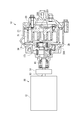
- FIG. 1st embodiment It is a figure showing a scroll compressor concerning a 1st embodiment.
- the main part is broken and shown. It is a top view which fractures
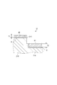
- a scroll compressor of a 2nd embodiment it is a sectional view showing a lap and an end plate in a level difference part.
- a scroll compressor of a 3rd embodiment it is a sectional view showing a lap and an end plate in a level difference part.
- the scroll compressor 10 illustrated in FIG. 1 is suitably used as a compressed air source for a brake of a railway vehicle, an air spring, and the like.
- the scroll compressor 10 includes a fixed scroll 20 fixed to a case (not shown), an orbiting scroll 30 which revolves with respect to the stationary scroll 20, and a motor 11 for applying a rotational force to the orbiting scroll 30.
- Scroll compressor 10 draws air between fixed scroll 20 and orbiting scroll 30 using motor 11 as a motive power source, and air compressed in a compression chamber S formed between stationary scroll 20 and orbiting scroll 30 Discharge.
- the scroll compressor 10 is an oil free type that does not use oil for sealing, cooling and lubrication of the scroll, unlike a conventional compressor for compressing oil for sealing, cooling and lubrication of the scroll with air.
- the scroll compressor 10 is housed in a case (not shown) together with a fan for cooling the motor 11 and the bearing portion, a device for cooling and dehumidifying compressed air to be discharged, an electrical component box, and the like.
- Grease is used to lubricate the motor 11 and the bearing portion.
- the motor 11 is configured to include a stator and a rotor housed in a motor case 12.
- the motor 11 outputs a rotational force by energizing the stator and rotating the rotor.
- the rotational force is transmitted to a shaft 15 coupled by a coupling 14 to an output shaft 13 provided on the rotor.
- an eccentric pin 151 eccentric to the axis is provided.
- the fixed scroll 20 includes a fixed end plate 200 and a spiral wrap 21 provided upright on one side of the fixed end plate 200.
- the orbiting scroll 30 also includes an orbiting end plate 300 and a spiral wrap 31 provided upright on one side of the orbiting end plate 300.
- the fixed scroll 20 and the orbiting scroll 30 are formed of metal such as aluminum, aluminum alloy, iron (cast iron, steel, etc.).
- the surface of the fixed scroll 20 and the orbiting scroll 30 may be subjected to surface treatment such as quenching or tempering, nitriding, carburizing or the like if the material is an aluminum material such as an alumite treatment if it is an aluminum material.
- the orbiting scroll 30 is coupled to the above-described eccentric pin 151 by a boss 34 provided on the back surface of the orbiting end plate 300.
- the orbiting scroll 30 revolves around the axis of the shaft 15 while the rotation of the orbiting scroll 30 is prevented by the Oldham ring (not shown).
- the wrap 21 of the fixed scroll 20 and the wrap 31 of the orbiting scroll 30 are offset from each other by a predetermined amount, and are engaged 180 degrees out of phase.
- a compression chamber S is formed in point symmetry with respect to the central portion (innermost peripheral portion) of the spirals of the wraps 21 and 31.
- a compression chamber S is formed in which the air sucked from the suction port IN is filled.
- the compression chamber S is gradually driven to the inner circumferential side while reducing its volume as the orbiting scroll 30 pivots.
- the air in the compression chamber S is discharged from the discharge port 201 (FIG. 1) formed at the center of the spiral in the fixed end plate 200.
- the scroll compressor 10 is a 3D type scroll compressor, and the volume of the compression chamber S formed between both the scrolls 20 and 30 decreases in the height direction of the wraps 21 and 31 in the middle of the spiral. . Therefore, in both the fixed scroll 20 and the orbiting scroll 30, as shown in FIG. 3, the height of the wraps 21 and 31 is lower on the inner peripheral side than the outer peripheral side, and the opposite end facing the wraps 21 and 31
- the plates 300 and 200 protrude on the inner peripheral side more to the inner side than the outer peripheral side. Therefore, step portions 21C and 31C are formed on each of the wraps 21 and 31 so as to lower from the outer peripheral side to the inner peripheral side, and on each of the end plates 300 and 200, from the outer peripheral side to the inner peripheral side.
- Stepped wall 20C, 30C which becomes high is formed.
- the step walls 20C and 30C are formed in an arc shape in plan view of the end plates 200 and 300.
- the wrap 21 of the fixed scroll 20 is divided into an inner circumferential wrap 21A located on the inner circumferential side than the stepped portion 21C and an outer circumferential wrap 21B located on the outer circumferential side than the stepped portion 21C.
- the bottom portion of the swing end plate 300 facing the wrap 21 is divided into an inner circumferential bottom portion 30A and an outer circumferential bottom portion 30B with the stepped wall 30C as a boundary.
- the wrap 31 of the orbiting scroll 30 is divided into an inner circumferential wrap 31A positioned on the inner circumferential side than the stepped portion 31C and an outer circumferential wrap 31B positioned on the outer circumferential side relative to the stepped portion 31C.
- the bottom of the fixed end plate 200 facing the wrap 31 is divided into an inner circumferential bottom 20A and an outer circumferential bottom 20B at the step wall 20C.
- an inner circumferential tip seal 41 is provided at the tip of the inner circumferential wrap 21 ⁇ / b> A of the fixed scroll 20.
- the inner circumferential tip seal 41 is interposed between the inner circumferential wrap 21 ⁇ / b> A and the inner circumferential bottom portion 30 ⁇ / b> A of the pivoting end plate 300.
- the inner circumferential tip seal 41 is provided substantially over the entire area from the beginning of the inner circumferential wrap 21A located near the stepped portion 21C to the end of the inner circumferential wrap 21A located at the center of the spiral.
- an outer peripheral tip seal 42 is provided at the tip of the outer peripheral wrap 21B of the fixed scroll 20.
- the outer circumferential tip seal 42 is interposed between the outer circumferential wrap 21 B and the outer circumferential bottom portion 30 B of the turning end plate 300.
- the outer circumferential tip seal 42 is provided substantially over the entire area from the start end of the outer circumferential wrap 21B located at the outermost circumference of the spiral to the end of the outer circumferential wrap 21B located near the stepped portion 21C.
- the inner circumferential tip seal 41 and the outer circumferential tip seal 42 are formed to have the same thickness.
- an inner circumferential tip seal 51 is provided at the tip of the inner circumferential wrap 31A.
- the inner circumferential tip seal 51 is interposed between the inner circumferential wrap 31 ⁇ / b> A and the inner circumferential bottom portion 20 ⁇ / b> A of the fixed end plate 200.
- the inner circumferential tip seal 51 is formed in the same manner as the inner circumferential tip seal 41.
- an outer circumferential tip seal 52 is provided at the tip of the outer circumferential wrap 31B.
- the outer circumferential tip seal 52 is interposed between the outer circumferential wrap 31 B and the outer circumferential bottom portion 20 B of the fixed end plate 200.
- the outer circumferential tip seal 52 is formed in the same manner as the outer circumferential tip seal 42.
- tip seals 41, 42, 51, 52 are accommodated in a seal groove D formed in a lap in which they are provided, as shown in FIG.
- compressed air is introduced to the back side of the tip seal along the seal groove D from the gap G between the inner wall of the seal groove D located on the inner circumferential side and the tip seal.
- the pressure on the surface side of the tip seal is lower than that on the back side, so the tip seal floats up from the seal groove D and is pressed against the end plate. Then, since the gap between the tip seal and the end plate is sealed, the compression chamber S is kept airtight.
- the present embodiment is characterized in that the materials of the inner circumferential tip seals 41 and 51 and the outer circumferential tip seals 42 and 52 are different.
- the material of the inner tip seal 41, 51 and the material of the outer tip seals 42, 52 are determined based on the temperature and pressure rising with the compression of the air.
- FIG. 5 shows how the temperatures of the wraps 21 and 31 rise from the outermost circumference (0 rad) of the spiral toward the center (innermost circumference) of the spiral.
- the range from 0 rad to 2 ⁇ rad corresponds to the rotation angle from the opening of the suction port IN to the closing thereof. In the range of the rotation angle, since the inside of the compression chamber S is under the external atmosphere of the scrolls 20 and 30, the temperature hardly rises. In the example shown in FIG.
- the temperature of the wraps 21 and 31 at 2 ⁇ rad from the outermost periphery remains at about 50 ° C.
- the temperature of the wraps 21 and 31 also increases with the temperature rise of the air due to compression, and rises to 225 ° C. in the center of the spiral (about 7 ⁇ rad).
- the temperature shown in FIG. 5 is an example.
- the gradient of the temperature or temperature rise changes according to the volume and compression ratio of the compression chamber S and the rotation angle from the outermost circumference to the innermost circumference of the wraps 21 and 31. In either case, the temperature rise from the outermost circumference to 2 ⁇ Is similar, and the temperature rises gradually as it goes to the central part over 2 ⁇ .
- the inner tip seal 41, 51 which is in charge of the inner circumferential side of the wraps 21, 31 including the central portion of the spiral is required to have heat resistance that can withstand the high temperature as described above.
- the inner circumferential tip seals 41 and 51 are strongly pressed against the end plates and slide compared to the outer circumferential tip seals 42 and 52, the inner circumferential tip seals 41 and 51 The frictional force between the and the end plate is large. Therefore, in order to prevent the inner tip seal 41, 51 from being worn out prematurely due to wear, the inner tip seal 41, 51 is also required to have wear resistance.
- the inner tip seal 41, 51 which is responsible for the high temperature inner circumferential side and also exerts frictional heat with the end plate, has a large thermal expansion.
- the inner circumferential tip seals 41 and 51 when the inner circumferential tip seals 41 and 51 are strongly pressed by the end plates, the wear becomes remarkable. In order to reduce the amount of wear, it is desirable that the inner circumferential tip seals 41 and 51 have a small linear expansion coefficient.
- the outer peripheral tip seals 41 and 51 may be pressed against the end plates 300 and 200 even if they are pressed against the end plates 300 and 200. A gap may occur between the tip seals 42, 52 and the end plates 300, 200. In order to avoid this, it is preferable to balance the linear expansion coefficient of the inner peripheral tip seals 41 and 51 and the linear expansion coefficient of the outer peripheral tip seals 42 and 52.
- the material of the inner tip seal 41, 51 is selected from resins or metals which satisfy the heat resistance and the abrasion resistance under the high temperature and high pressure conditions as described above.
- the resin that can be used for the inner circumferential tip seals 41 and 51 include PI (polyimide), PEEK (polyether ether ketone), PTFE (polytetrafluoroethylene) and the like.
- PAI polyamide imide
- PPS polyphenylene sulfide
- the inner tip seal 41, 51 can be formed by injection molding or the like from the above-described resin.
- the inner tip seal 41, 51 can also be formed, for example, from a metal such as iron by press punching or the like.
- the respective materials of the inner circumferential tip seals 41 and 51 may be different.
- PI (example): 240 ° C., 1.7 to 4.5 ⁇ 10 ⁇ 5 / ° C.
- PEEK (example): 260 ° C, 3.0 to 5.7 ⁇ 10 -5 / ° C
- PTFE (example): 260 ° C., 8.3 to 15.2 ⁇ 10 ⁇ 5 / ° C.
- PAI (example): 250 ° C, 4.0 ⁇ 10 -5 / ° C
- PPS (example): 230 ° C, 1.8 to 8.7 ⁇ 10 -5 / ° C
- the heat resistance and wear resistance required for the inner circumferential tip seals 41, 51 vary depending on the temperature and pressure at the center of the spiral. In the example shown in FIG. 5, it is preferable that the heat-resistant temperature of the inner peripheral chip seals 41 and 51 is 240 ° C. or higher.
- the outer peripheral tip seals 42 and 52 handle the outer peripheral side of the wraps 21 and 31 including the outermost periphery where air is sucked, the temperature rise is small, and the back pressure is lower than the inner peripheral side, and the pressing load is also small. . Therefore, the outer circumferential tip seals 42, 52 may have lower heat resistance and wear resistance than the inner circumferential tip seals 41, 51, and may have a high linear expansion coefficient.
- resins that can be used for the outer peripheral chip seals 42 and 52 include PAI (polyamide imide), PPS (polyphenylene sulfide), PA (polyamide) and the like. Besides, PTFE (polytetrafluoroethylene) can also be adopted.
- the outer circumferential tip seals 42, 52 can also be formed of metal such as iron.
- both the inner peripheral tip seals 41 and 51 and the outer peripheral tip seals 42 and 52 may be formed of materials having the same heat resistance temperature and different specific wear amounts or linear expansion coefficients. Alternatively, both are formed of materials having similar specific wear amounts and different heat resistance temperatures or linear expansion coefficients, or formed of materials having similar linear expansion coefficients and different heat resistance temperatures or specific wear amounts.
- the outer tip seal 42, 52 has necessary heat resistance and wear resistance. As long as the above condition is satisfied, a material cheaper than the material of the inner tip seal 41, 51 is used.
- the positions of the step portions 21C and 31C separating the inner chip seal 41, 51 and the outer chip seal 42, 52 are set.
- the positions of the step portions 21C and 31C refer to portions where the outer peripheral wrap 21B rises from the inner peripheral wrap 21A.
- the first index is an angle corresponding to the center value of the temperature range in which the temperature of the wraps 21 and 31 rises.
- the second index is 2 ⁇ rad, which is the rotation angle when the orbiting scroll 30 makes one rotation.
- the temperature range of the wraps 21 and 31 is from 25 ° C. at 0 rad to 225 ° C. at about 7 ⁇ rad, and its center value is 125 ° C.
- the rotation angle corresponding to the center value 125 ° C. is 4 ⁇ rad (first index).
- 2 ⁇ rad (second index) corresponding to one rotation corresponds to a rotation angle from the opening of the suction port IN to the outermost periphery of the wraps 21 and 31 until the suction port IN is closed.
- the 2 ⁇ rad is used to reliably obtain a cost reduction effect by selecting an inexpensive material for the outer peripheral tip seals 42 and 52.
- the positions of the step portions 21C and 31C in the range of 2 ⁇ rad or more and 4 ⁇ rad or less from the outermost periphery of the wraps 21 and 31 using the first and second indicators.
- the heat-resistant temperature of the outer peripheral tip seals 42, 52 can be suppressed to a temperature equal to or less than the central value of the rising temperature range.
- the lengths of the outer peripheral chip seals 42 and 52 can be secured to 2 ⁇ rad or more. Then, cost reduction effects can be reliably obtained by selecting inexpensive materials for the outer peripheral tip seals 42 and 52.
- the positions of the step portions 21C and 31C are set to 2 ⁇ , but the step portions 21C, 21C and 31C can be provided at any position in the range of 2 ⁇ rad or more and 4 ⁇ rad or less from the outermost periphery of the wraps 21 and 31 31C can be provided.
- the steps portions 21C and 31C are 3 ⁇ rad or more from the outermost periphery to the inner peripheral side, the step portions 21C and 31C are in the compression chamber S when the suction port IN is closed and the inside of the compression chamber S is closed. Does not exist.
- the compression chamber S has a uniform space between the end plates 200 and 300, and the volume does not decrease in the height direction of the wraps 21 and 31.
- the compression ratio can be secured large.
- a slight error due to a dimensional error or an assembly error of the scrolls 20 and 30 is allowed at the positions of the step portions 21C and 31C.
- the outer circumferential tip seals 42 and 52 are formed of inexpensive materials while the inner circumferential tip seals 41 and 51 are formed of a material which is derived from the high temperature and high pressure at the central portion of the spiral. Therefore, the state in which the gap between the wraps 21 and 31 and the end plates 300 and 200 is sealed is maintained without causing the chip seal to melt, abnormal wear, seizing or the like, and the reliability of the scroll compressor 10 is improved. While being able to ensure, it can also contribute to cost reduction.
- the inner tip seal 41 has a wear resistant coating 45 on the surface.
- a material of the coating 45 for example, PTFE (polytetrafluoroethylene), PEEK (polyether ether ketone), DLC (diamond like carbon), TiN (titanium nitride), CrN (chromium nitride) or the like can be used.
- the abrasion resistance of the coating 45 is appropriately set according to the pressure at the center of the spiral.
- the film thickness of the coating 45 can be set in accordance with the specific wear amount required for the coating 45.
- the coating 45 constitutes at least a surface 45S (surface) facing the inner peripheral bottom portion 30A of the end plate 300 in the inner circumferential tip seal 41, and faces the opposite end plate 300.
- the material of the portion (coating 45) facing the end plate 300 of the inner circumferential tip seal 41 is different from the material of the portion facing the end plate 300 of the outer circumferential tip seal 42 which is not coated.
- the inner circumferential tip seal 51 can also be coated with the same coating 45 as the inner circumferential tip seal 41.
- the coating 45 of PTFE and PEEK is coated by spraying a liquid obtained by mixing resin powder in a solution onto the inner tip seal 41, 51 (base material) with an air spray gun, and heating at a temperature above the melting point of the resin. It can be formed by welding. Painting and heating are repeated until a predetermined film thickness is obtained.
- an air spray method there is also an electrostatic powder coating method in which resin powder is coated on a substrate using static electricity, a dip (dip) method, etc. Is welded to the substrate.
- the coating 45 of DLC can be formed by plasma-enhanced chemical vapor deposition (PECVD) or physical vapor deposition (PVD).
- the coating 45 of TiN and CrN can be formed by PVD.
- the material of the base material of the inner tip seal 41, 51 on which the coating 45 is formed is selected so as not to melt by the heat applied in the process of forming the coating 45.
- the base material of the inner circumferential tip seals 41, 51 can be made of the same material as the outer circumferential tip seals 42, 52.
- the inner circumferential tip seals 41 and 51 can have higher wear resistance than the outer circumferential tip seals 42 and 52. Therefore, by making the material of the base material of the inner peripheral tip seals 41, 51 the same as the material of the outer peripheral tip seals 42, 52, the necessary wear resistance can be realized while suppressing the material cost. Also, even if it is difficult to use as the material of the base material of the chip seal in terms of thickness and cost, by selecting the material of the coating 45 that is superior in wear resistance to the material that can be used as the base material. And abrasion resistance can be further improved.
- the coefficient of friction of the surface of the inner tip seal 41, 51 decreases.
- the friction coefficient of DLC is about 0.1 (drying condition).
- the abrasion resistance can be increased also at the point where the amount of abrasion decreases because the coefficient of friction is small.
- the base material of the inner circumferential tip seals 41, 51 may be formed of a material different from the material of the outer circumferential tip seals 42, 52. It is also permissible to apply a coating of a material different from the coating 45 applied to the inner peripheral tip seals 41, 51 to the outer peripheral tip seals 42, 52.
- a third embodiment of the present invention will be described with reference to FIG. Also in the third embodiment, differences from the first embodiment are mainly described, and the same reference numerals are given to the same components as the components described above.
- the thicknesses of both the inner circumferential tip seal and the outer circumferential tip seal are different.
- the materials of both the inner circumferential tip seal and the outer circumferential tip seal are the same.
- the thickness of each of the inner circumferential tip seal 61 provided on the inner circumferential wrap 21A and the outer circumferential tip seal 42 provided on the outer circumferential wrap 21B is different.
- the inner circumferential tip seal provided on the inner circumferential wrap 31 A is formed in the same manner as the inner circumferential tip seal 61, and the outer circumferential tip seal provided on the outer circumferential wrap 31 B is also formed similarly to the outer circumferential tip seal 42.
- the thickness of the outer circumferential tip seal 42 is set to T1. This thickness is the same as the thickness of the outer peripheral tip seal 42 in the first embodiment and the second embodiment.
- the thickness T 2 of the inner circumferential tip seal 61 is larger than the thickness T 1 of the outer circumferential tip seal 42.
- the inner circumferential tip seal 61 is thick, even if the inner circumferential tip seal 61 is worn out to a large extent, a thickness sufficient for sealing can be left. Thereby, the reliability of the tip seal can be secured. In addition, since the thickness T1 of the outer circumferential tip seal 42 can be maintained to a thickness sufficient for sealing, the cost can be suppressed.
- the third embodiment can also be combined with the first embodiment or the second embodiment. That is, in the third embodiment, both the inner circumferential tip seals 41 and 51 and the outer circumferential tip seals 42 and 52 may be formed of different materials, or the inner circumferential tip seals 41 and 51 may be coated with the coating 45. .
- the configuration of each of the first to third embodiments makes the inner circumferential tip seal durable. Providing the property is effective in the air-compressing scroll compressor.
- the scroll compressor 10 is oil free, the temperature rise on the inner circumferential side becomes remarkable because the effect of cooling by the oil can not be obtained.
- the lubricating action by oil can not be obtained, and the tip seal is apt to be worn because it is slid directly on the end plate without lubricating oil. Therefore, when the present invention is applied to an air-compressed and oil-free scroll compressor, the effects of the present invention are remarkable. Even in the scroll compressor that compresses the refrigerant, the high temperature and high compression ratio may be as high as that of air compression at the center of the spiral like a scroll compressor used for a large freezer or an air conditioner. Also in that case, the effect of the present invention is great. The effect of the present invention is also remarkable in such an oil-free scroll compressor which performs refrigerant compression.
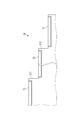
- the stepped portion is provided only at one place in the circumferential direction of the wrap, but the stepped portions may be provided at a plurality of places in the circumferential direction of the wrap. For example, as shown in FIG. 8, if the step portions 211 and 212 are provided at two places in the circumferential direction of the wrap 21, the innermost chip seal provided at the position including the innermost circumference (central part of the spiral) 71, an outermost tip seal 73 provided at a position including the outermost circumference, and an intermediate tip seal 72 provided at an intermediate position.
- first step portion 211 one located on the outer peripheral side
- second step portion 212 one located on the inner peripheral side
- the thickness can be made different.
- the innermost tip seal 71 positioned on the inner peripheral side of the second stepped portion 212 with respect to the second stepped portion 212, the intermediate tip seal 72 positioned on the outer peripheral side of the second stepped portion 212, and the outermost The material or thickness can be made different from that of the outer circumferential tip seal 73. Furthermore, the material or thickness of each of the outermost tip seal 73, the middle tip seal 72, and the innermost tip seal 71 may be made different stepwise.
- the intermediate chip seal 72 positioned on the inner circumferential side of the first step portion 211 and the outermost tip seal 73 positioned on the outer circumferential side of the first step portion 211 are different in material or thickness
- the material or thickness can be made different between the innermost tip seal 71 positioned on the inner circumferential side of the two step portion 212 and the intermediate tip seal 72 positioned on the outer side of the second step portion 212.
- the temperature and pressure of the gas increase from the outermost periphery to the innermost periphery of the lap, the temperature is higher on the inner periphery side and the pressure is higher.
- the material of the inner tip seal is made more excellent in heat resistance and wear resistance than the outer tip seal located relatively on the outer circumferential side, and the thickness of the inner tip seal is thicker than the outer tip seal. Just do it.
- the scroll compressor according to the present invention is not limited to one driven by the rotational force of the motor, and may be driven by the driving force transmitted from the engine to the shaft via the belt.
Landscapes
- Engineering & Computer Science (AREA)
- Mechanical Engineering (AREA)
- General Engineering & Computer Science (AREA)
- Rotary Pumps (AREA)
- Applications Or Details Of Rotary Compressors (AREA)
Abstract
3Dタイプのスクロール圧縮機において、チップシールの耐久性向上により、スクロール圧縮機の信頼性を向上させることを目的とする。 3Dタイプのスクロール圧縮機10において、一対のスクロール20,30は、段差部21C,31Cを経て高さが低くなるラップ21,31と、相手側のラップ31,21の段差部31C,21Cに倣って立ち上がる段差壁20C,30Cが形成される端板200,300と、を備えてなる。段差部21C(31C)よりも内周側に設けられて端板300(200)との間に介在する内周チップシール41(51)と、段差部21C(31C)よりも外周側に設けられて端板300(200)との間に介在する外周チップシール42(52)とは、少なくとも端板300(200)に対向する部分の材質が相違する。
Description
本発明は、スクロール圧縮機に関する。
スクロール圧縮機は、固定スクロールと、旋回スクロールとを備えている。固定スクロールおよび旋回スクロールは、いずれも円板状の端板の一面側に、渦巻状のラップが設けられたものである。このような固定スクロールと旋回スクロールとを、ラップを噛み合わせた状態で対向させ、固定スクロールに対して旋回スクロールを公転旋回運動させる。すると、ラップの最外周から吸い込まれた気体が、双方のスクロールの間の圧縮室に満たされ、圧縮室の容積が旋回スクロールの旋回に伴って減少することで、気体が圧縮される。気体は、端板の中心部に位置するポートから、最大に圧縮された状態で吐出される。
一般に、固定スクロールおよび旋回スクロールの双方のラップの先端には、チップシールが設けられる。チップシールを収容するシール溝には、圧縮された気体が導入される。チップシールは、圧縮気体によって生じる背圧により、端板に押し付けられることでラップと端板との隙間を封止する。
特許文献1に記載されたスクロール圧縮機では、チップシールが周方向に2つに分割された上で、一体に連接される。ラップの内周側に位置するチップシールは、外周側に位置するチップシールよりも、耐熱性、耐摩耗性に優れた材質から形成する。
特許文献1に記載されたスクロール圧縮機では、チップシールが周方向に2つに分割された上で、一体に連接される。ラップの内周側に位置するチップシールは、外周側に位置するチップシールよりも、耐熱性、耐摩耗性に優れた材質から形成する。
ところで、スクロール圧縮機において、圧縮室の容積を周方向のみならず高さ方向にも減少させることで高い圧縮比を得るために、ラップの高さを内周側では外周側よりも低くし、それに対応して、相手側の端板を内周側では外周側よりも内面側に突出するように形成したものがある(特許文献2)。この3Dスクロール(登録商標)と呼ばれるタイプのスクロール圧縮機では、ラップおよび端板の双方に段差が形成される。
このような三次元タイプ(3Dタイプ)のスクロール圧縮機では、特許文献2に示すように、ラップの段差よりも内周側と、外周側とにチップシールが分けて配置される。
このような三次元タイプ(3Dタイプ)のスクロール圧縮機では、特許文献2に示すように、ラップの段差よりも内周側と、外周側とにチップシールが分けて配置される。
スクロール圧縮機では、スクロールの中心部に近いほど高圧、高温となる。チップシールには、中心部の高圧による押し付け荷重、および高温に耐えるために高い耐摩耗性、耐熱性が求められる。
しかし、一般に、高い耐摩耗性、耐熱性を備える材質は高価なため、チップシールの材質は、コストも考慮して選択される。
ここで、特許文献1のようにチップシールを分割すると、部品点数が増え、チップシール同士を接合するためのコストを必要とする。特許文献1のように3Dタイプではない普通のスクロール圧縮機であれば、一般に、最外周から最内周までのラップ全体に亘り、同じ材質から作られた一体のチップシールを設ける。
しかし、一般に、高い耐摩耗性、耐熱性を備える材質は高価なため、チップシールの材質は、コストも考慮して選択される。
ここで、特許文献1のようにチップシールを分割すると、部品点数が増え、チップシール同士を接合するためのコストを必要とする。特許文献1のように3Dタイプではない普通のスクロール圧縮機であれば、一般に、最外周から最内周までのラップ全体に亘り、同じ材質から作られた一体のチップシールを設ける。
一方、3Dタイプのスクロール圧縮機では、ラップの段差の前後(内・外)に亘って一体にチップシールを作ることが困難である。このため、3Dタイプのスクロール圧縮機では、特許文献2のように、チップシールがラップの段差よりも内周側と外周側とに必然的に分割される。
本発明は、3Dタイプのスクロール圧縮機ではラップの段差の前後でチップシールが分割されることに着目してなされたものであり、チップシールの耐久性向上により、3Dタイプのスクロール圧縮機の信頼性を向上させることを目的とする。
本発明は、3Dタイプのスクロール圧縮機ではラップの段差の前後でチップシールが分割されることに着目してなされたものであり、チップシールの耐久性向上により、3Dタイプのスクロール圧縮機の信頼性を向上させることを目的とする。
本発明は、固定スクロールおよび旋回スクロールを備え、固定スクロールおよび旋回スクロールがいずれも、外周側から内周側へと段差部を経て高さが低くなる渦巻状のラップと、相手側のラップの段差部に倣って立ち上がる段差壁が形成される端板と、を有するスクロール圧縮機である。
そして、本発明は、段差部よりも内周側に設けられて相手側の端板との間に介在する内周チップシールと、段差部よりも外周側に設けられて相手側の端板との間に介在する外周チップシールとは、少なくとも端板に対向する部分の材質が相違することを特徴とする。
そして、本発明は、段差部よりも内周側に設けられて相手側の端板との間に介在する内周チップシールと、段差部よりも外周側に設けられて相手側の端板との間に介在する外周チップシールとは、少なくとも端板に対向する部分の材質が相違することを特徴とする。
本発明によれば、3Dスクロールのラップの段差部の前後で必然的に分割して形成されるチップシールのうち、内周チップシールだけを、スクロールの中心部の温度や圧力に基づく所望の条件を満足する材質から形成し、外周チップシールについては、他の安価な材質から形成することが可能となる。
また、3Dタイプのスクロール圧縮機では、内周チップシールと外周チップシールとが段差部により隔てられて分離した状態で配置されることを想定するため、内周チップシールおよび外周チップシールの両者を接合するためのコストを必要としない。
したがって、本発明によれば、内周チップシールおよび外周チップシールの両者を同じ材質から形成する場合と比べて、コストを抑えつつ、チップシールの耐久性を向上させることができる。
内周チップシールおよび外周チップシールにおいて、少なくとも端板に対向する部分の材質が相違すれば、本発明の目的を担保できる。
また、3Dタイプのスクロール圧縮機では、内周チップシールと外周チップシールとが段差部により隔てられて分離した状態で配置されることを想定するため、内周チップシールおよび外周チップシールの両者を接合するためのコストを必要としない。
したがって、本発明によれば、内周チップシールおよび外周チップシールの両者を同じ材質から形成する場合と比べて、コストを抑えつつ、チップシールの耐久性を向上させることができる。
内周チップシールおよび外周チップシールにおいて、少なくとも端板に対向する部分の材質が相違すれば、本発明の目的を担保できる。
本発明のスクロール圧縮機では、段差部が、ラップの最外周の回転角からラップの最内周の回転角までの間にラップの温度が上昇する温度域の中心値をとる回転角よりも外周側に位置し、内周チップシールが、外周チップシールの材質よりも、耐熱温度が高いこと、比摩耗量が小さいこと、および線膨張係数が小さいことの少なくとも一の要件を満たす材質から形成されることが好ましい。
「耐熱温度」は、連続して使用される場合に、外観変化や力学的特性の低下が発生しない温度をいうものとする。
「比摩耗量」は、体積で表した摩耗量を、摺動した距離および垂直方向の荷重で割ることで導かれる。
摩耗し難い材質は比摩耗量が小さい。また、線膨張係数が小さいと、熱膨張によりチップシールが端板に強く押し付けられるのを避けられるので摩耗し難い。本発明において、比摩耗量および線膨張係数は、摩擦のある状況でどれだけ削られる体積が小さいかを表す耐摩耗性に係る尺度である。
本明細書におけるチップシールの「耐久性」は、耐熱温度が示す耐熱性と、上記の耐摩耗性を包含するものとする。
「比摩耗量」は、体積で表した摩耗量を、摺動した距離および垂直方向の荷重で割ることで導かれる。
摩耗し難い材質は比摩耗量が小さい。また、線膨張係数が小さいと、熱膨張によりチップシールが端板に強く押し付けられるのを避けられるので摩耗し難い。本発明において、比摩耗量および線膨張係数は、摩擦のある状況でどれだけ削られる体積が小さいかを表す耐摩耗性に係る尺度である。
本明細書におけるチップシールの「耐久性」は、耐熱温度が示す耐熱性と、上記の耐摩耗性を包含するものとする。
本発明は、上述のように、内周チップシールおよび外周チップシールの各々の材質が、端板に対向する部分のみで相違する構成をも包含する。
そのような構成としては、内周チップシールにおいて端板に対向する部分の材質の耐熱温度が外周チップシールにおいて端板に対向する部分の材質の耐熱温度よりも高いこと、内周チップシールにおいて端板に対向する部分の材質の比摩耗量が外周チップシールにおいて端板に対向する部分の材質の比摩耗量よりも小さいこと、内周チップシールにおいて端板に対向する部分の材質の線膨張係数が外周チップシールにおいて端板に対向する部分の材質の線膨張係数よりも小さいことが挙げられる。これらのいずれの構成によっても、内周チップシールの耐久性向上に寄与することができる。
そのような構成としては、内周チップシールにおいて端板に対向する部分の材質の耐熱温度が外周チップシールにおいて端板に対向する部分の材質の耐熱温度よりも高いこと、内周チップシールにおいて端板に対向する部分の材質の比摩耗量が外周チップシールにおいて端板に対向する部分の材質の比摩耗量よりも小さいこと、内周チップシールにおいて端板に対向する部分の材質の線膨張係数が外周チップシールにおいて端板に対向する部分の材質の線膨張係数よりも小さいことが挙げられる。これらのいずれの構成によっても、内周チップシールの耐久性向上に寄与することができる。
内周チップシールの材質が上記の一の要件を満たすことにより、チップシールの耐久性を向上させることができる。
さらに、外周チップシールの耐熱温度を上昇温度域の中心値以下の温度に抑えられるので、耐熱温度がさほど高くない、より安価な材質を外周チップシールの材質として選択することができる。
さらに、外周チップシールの耐熱温度を上昇温度域の中心値以下の温度に抑えられるので、耐熱温度がさほど高くない、より安価な材質を外周チップシールの材質として選択することができる。
本発明のスクロール圧縮機では、段差部が、ラップの最外周の回転角からラップの最内周の回転角までの間にラップの温度が上昇する温度域の中心値をとる回転角よりも外周側に位置し、内周チップシールの少なくとも端板に対向する部分は、耐摩耗性を有する材質のコーティングから構成されることが好ましい。
「コーティング」は、塗装、めっき、スパッタ、化学気相成長法、物理気相成長法などの任意の方法によりチップシールの基材表面に設けられる被膜である。コーティングは、基材表面に設けられる1つ以上の層から構成することができる。
「コーティング」は、塗装、めっき、スパッタ、化学気相成長法、物理気相成長法などの任意の方法によりチップシールの基材表面に設けられる被膜である。コーティングは、基材表面に設けられる1つ以上の層から構成することができる。
内周チップシールの少なくとも端板に対向する部分をコーティングから構成することにより、内周チップシールに外周チップシールよりも高い耐摩耗性を持たせることができる。したがって、内周チップシールの基材の材質を外周チップシールの基材と同じとすることで材料費を抑えながら、必要な耐摩耗性を実現できる。
また、チップシールの基材の材質に使用することが難しくても、基材に使用可能な材質よりも耐摩耗性に優れた材質をコーティングの材質に選択することにより、耐摩耗性を一層向上させることができる。
さらに、コーティングを施すことにより、基材の表面よりも滑らかな表面が得られれば、内周チップシールの表面の摩擦係数が小さくなる。そのために摩耗量が減る点でも、耐摩耗性を高くすることができる。
また、チップシールの基材の材質に使用することが難しくても、基材に使用可能な材質よりも耐摩耗性に優れた材質をコーティングの材質に選択することにより、耐摩耗性を一層向上させることができる。
さらに、コーティングを施すことにより、基材の表面よりも滑らかな表面が得られれば、内周チップシールの表面の摩擦係数が小さくなる。そのために摩耗量が減る点でも、耐摩耗性を高くすることができる。
本発明のスクロール圧縮機では、段差部が、ラップの最外周の回転角からラップの最内周の回転角までの間にラップの温度が上昇する温度域の中心値をとる回転角よりも外周側に位置し、内周チップシールの厚み寸法は、外周チップシールの厚み寸法よりも大きいことが好ましい。
チップシールは、端板に押し付けられて摺動することで少しずつ摩耗していくので、定期的に交換される。背圧による押し付け荷重が大きい内周チップシールは外周チップシールよりも摩耗し易い。
そこで、内周チップシールを厚くすれば、内周チップシールが大きく摩耗したとしても、封止に足りる厚みを残すことができる。これにより、チップシールの信頼性を確保できるとともに、交換の頻度を減らすことができる。
また、外周チップシールの厚みを封止に足りる程度の厚みに維持できるので、コストを抑えることができる。
そこで、内周チップシールを厚くすれば、内周チップシールが大きく摩耗したとしても、封止に足りる厚みを残すことができる。これにより、チップシールの信頼性を確保できるとともに、交換の頻度を減らすことができる。
また、外周チップシールの厚みを封止に足りる程度の厚みに維持できるので、コストを抑えることができる。
本発明のスクロール圧縮機は、固定スクロールおよび旋回スクロールを備え、固定スクロールおよび旋回スクロールがいずれも、外周側から内周側へと段差部を経て高さが低くなる渦巻状のラップと、相手側のラップの段差部に倣って立ち上がる段差壁が形成される端板と、を有するスクロール圧縮機であって、
段差部よりも内周側に設けられて相手側の端板との間に介在する内周チップシールの厚み寸法は、段差部よりも外周側に設けられて相手側の端板との間に介在する外周チップシールの厚み寸法よりも大きいことを特徴とする。
段差部よりも内周側に設けられて相手側の端板との間に介在する内周チップシールの厚み寸法は、段差部よりも外周側に設けられて相手側の端板との間に介在する外周チップシールの厚み寸法よりも大きいことを特徴とする。
本発明も、3Dタイプのスクロール圧縮機ではラップの段差の前後でチップシールが分割されることを利用している。
ラップに段差が形成されていない普通のスクロール圧縮機の場合、内周チップシールおよび外周チップシールの厚みが異なれば、チップシールを収容するシール溝の底部に段差を付けるとともに、内周チップシールおよび外周チップシールを接合する。その場合、シール溝の段差の位置とチップシールの接合位置とがずれて漏れの原因となり易い。
ラップに段差が形成されていない普通のスクロール圧縮機の場合、内周チップシールおよび外周チップシールの厚みが異なれば、チップシールを収容するシール溝の底部に段差を付けるとともに、内周チップシールおよび外周チップシールを接合する。その場合、シール溝の段差の位置とチップシールの接合位置とがずれて漏れの原因となり易い。
本発明では、3Dスクロールのラップの段差部の前後で必然的に分割して形成されるチップシールのうち、内周チップシールの厚みを外周チップシールの厚みよりも大きくする。
そうすると、背圧による押し付け荷重が大きい内周チップシールが大きく摩耗したとしても、封止に足りる厚みを残すことができる。これにより、チップシールの耐久性、信頼性を向上させることができる。
また、外周チップシールの厚みを封止に足りる程度の厚みに維持できるので、コストを抑えることができる。
そうすると、背圧による押し付け荷重が大きい内周チップシールが大きく摩耗したとしても、封止に足りる厚みを残すことができる。これにより、チップシールの耐久性、信頼性を向上させることができる。
また、外周チップシールの厚みを封止に足りる程度の厚みに維持できるので、コストを抑えることができる。
上記の各スクロール圧縮機において、段差部が、ラップの最外周の回転角から内周側へ2πを超える回転角領域に位置することが好ましい。
2πは、旋回スクロールが一回転する間の回転角に相当する。旋回スクロールが一回転する間に、ラップの最外周に吸込口が開き、再び閉じられる。
段差部が最外周から2πを超えた位置にあることで、外周チップシールの長さを2π以上に確保することができる。そうすると、外周チップシールに安価な材質を用いることによるコスト低減効果を確実に得ることができる。
また、段差部が、ラップの最外周の回転角から内周側へ3πを超える回転角領域に位置することがより好ましい。
段差部が最外周から3πを超えた位置にあれば、吸込口が閉じて圧縮室内が締め切られるとき、圧縮室内に段差部が存在せず、圧縮室は、ラップの高さ方向に容積が減少しない。そのため、最外周に位置する圧縮室の容積を最大に確保できるので、圧縮比を大きく確保できる。
2πは、旋回スクロールが一回転する間の回転角に相当する。旋回スクロールが一回転する間に、ラップの最外周に吸込口が開き、再び閉じられる。
段差部が最外周から2πを超えた位置にあることで、外周チップシールの長さを2π以上に確保することができる。そうすると、外周チップシールに安価な材質を用いることによるコスト低減効果を確実に得ることができる。
また、段差部が、ラップの最外周の回転角から内周側へ3πを超える回転角領域に位置することがより好ましい。
段差部が最外周から3πを超えた位置にあれば、吸込口が閉じて圧縮室内が締め切られるとき、圧縮室内に段差部が存在せず、圧縮室は、ラップの高さ方向に容積が減少しない。そのため、最外周に位置する圧縮室の容積を最大に確保できるので、圧縮比を大きく確保できる。
本発明のスクロール圧縮機は、冷媒、空気など、圧縮対象である作動流体を選ばないが、特に、空気圧縮のスクロール圧縮機に好適に用いることができる。空気圧縮の場合、スクロールの中心部の昇温が顕著となるので、内周チップシールに耐久性を持たせることのできる本発明の効果が大きい。
また、本発明は、スクロールのシール、冷却、潤滑のためにオイルを用いるタイプのスクロール圧縮機にも、オイルを用いないオイルフリーのタイプのスクロール圧縮機にも適用できるが、特に、オイルフリーのタイプのスクロール圧縮機に有用である。オイルフリーのタイプでは、チップシールがオイル(潤滑油)を介さずに直接、端板に対して摺動されるので、内周側における昇温が顕著となるためである。
以上より、空気圧縮でかつオイルフリーのスクロール圧縮機に本発明を適用すると、本発明の効果が際立つ。
また、本発明は、スクロールのシール、冷却、潤滑のためにオイルを用いるタイプのスクロール圧縮機にも、オイルを用いないオイルフリーのタイプのスクロール圧縮機にも適用できるが、特に、オイルフリーのタイプのスクロール圧縮機に有用である。オイルフリーのタイプでは、チップシールがオイル(潤滑油)を介さずに直接、端板に対して摺動されるので、内周側における昇温が顕著となるためである。
以上より、空気圧縮でかつオイルフリーのスクロール圧縮機に本発明を適用すると、本発明の効果が際立つ。
本発明によれば、チップシールの耐久性向上により、信頼性が向上された3Dタイプのスクロール圧縮機を提供することができる。
以下、添付図面を参照し、本発明の実施形態について説明する。
〔第1実施形態〕
図1に示すスクロール圧縮機10は、圧縮空気源として鉄道車両のブレーキや空気ばねなどに好適に用いられる。
スクロール圧縮機10は、図示しないケースに固定される固定スクロール20と、固定スクロール20に対して公転旋回運動される旋回スクロール30と、旋回スクロール30に回転力を与えるモータ11とを備える。
スクロール圧縮機10は、モータ11を動力源として、固定スクロール20と旋回スクロール30との間に空気を吸い込み、固定スクロール20と旋回スクロール30との間に形成される圧縮室Sにおいて圧縮された空気を吐出する。
〔第1実施形態〕
図1に示すスクロール圧縮機10は、圧縮空気源として鉄道車両のブレーキや空気ばねなどに好適に用いられる。
スクロール圧縮機10は、図示しないケースに固定される固定スクロール20と、固定スクロール20に対して公転旋回運動される旋回スクロール30と、旋回スクロール30に回転力を与えるモータ11とを備える。
スクロール圧縮機10は、モータ11を動力源として、固定スクロール20と旋回スクロール30との間に空気を吸い込み、固定スクロール20と旋回スクロール30との間に形成される圧縮室Sにおいて圧縮された空気を吐出する。
スクロール圧縮機10は、スクロールのシール、冷却、潤滑のためのオイルを空気と共に圧縮する従来のものとは異なり、スクロールのシール、冷却、潤滑のためにオイルを使用しないオイルフリータイプとされる。
スクロール圧縮機10は、モータ11や軸受部を冷却するファンや、吐出する圧縮空気を冷却、除湿する装置、および電装ボックスなどと共に、図示しないケースに収容される。
なお、モータ11や軸受部の潤滑にはグリースが用いられる。
スクロール圧縮機10は、モータ11や軸受部を冷却するファンや、吐出する圧縮空気を冷却、除湿する装置、および電装ボックスなどと共に、図示しないケースに収容される。
なお、モータ11や軸受部の潤滑にはグリースが用いられる。
モータ11は、モータケース12に収容されたステータおよびロータを備えて構成される。
モータ11は、ステータに通電し、ロータを回転させることで、回転力を出力する。回転力は、ロータに設けられた出力軸13にカップリング14で結合されたシャフト15に伝達される。
シャフト15の端部には、軸心に対して偏心した偏心ピン151が設けられる。
モータ11は、ステータに通電し、ロータを回転させることで、回転力を出力する。回転力は、ロータに設けられた出力軸13にカップリング14で結合されたシャフト15に伝達される。
シャフト15の端部には、軸心に対して偏心した偏心ピン151が設けられる。
固定スクロール20は、固定端板200と、固定端板200の一面側に立設される渦巻状のラップ21とを備えている。
旋回スクロール30も、旋回端板300と、旋回端板300の一面側に立設される渦巻状のラップ31とを備えている。
固定スクロール20および旋回スクロール30は、アルミニウムやアルミニウム合金、鉄(鋳鉄、鋼等)等の金属から形成される。固定スクロール20および旋回スクロール30の表面には、アルミニウム系材ならアルマイト処理等、鉄鋼材なら焼入・焼戻、窒化、浸炭等の表面処理を施すこともできる。
旋回スクロール30も、旋回端板300と、旋回端板300の一面側に立設される渦巻状のラップ31とを備えている。
固定スクロール20および旋回スクロール30は、アルミニウムやアルミニウム合金、鉄(鋳鉄、鋼等)等の金属から形成される。固定スクロール20および旋回スクロール30の表面には、アルミニウム系材ならアルマイト処理等、鉄鋼材なら焼入・焼戻、窒化、浸炭等の表面処理を施すこともできる。
旋回スクロール30は、旋回端板300の背面に設けられるボス34により、上述の偏心ピン151に対して結合される。シャフト15が回転すると、旋回スクロール30は、図示しないオルダムリングにより自転が阻止されながら、シャフト15の軸心に対して公転旋回運動される。
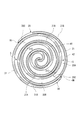
図2に示すように、固定スクロール20のラップ21および旋回スクロール30のラップ31は、互いに所定量だけ偏心し、180度位相をずらして噛み合わせられる。
固定スクロール20と旋回スクロール30との間には、ラップ21,31の渦巻きの中心部(最内周部)に対して点対称に圧縮室Sが形成される。
図2に示す状態から旋回スクロール30が旋回すると、ラップ21の最外周の端部とラップ31との間に空気の吸込口INが形成されるとともに、ラップ31の最外周の端部とラップ21との間にも空気の吸込口INが形成される。
吸込口INが、旋回スクロール30の旋回に伴って、図2に示すように閉じると、吸込口INから吸い込まれた空気が満たされる圧縮室Sが形成される。圧縮室Sは、旋回スクロール30の旋回に伴って、容積を減少させながら次第に内周側に追い込まれる。圧縮室S内の空気は、固定端板200において渦巻きの中心部に形成された吐出ポート201(図1)から吐出される。
固定スクロール20と旋回スクロール30との間には、ラップ21,31の渦巻きの中心部(最内周部)に対して点対称に圧縮室Sが形成される。
図2に示す状態から旋回スクロール30が旋回すると、ラップ21の最外周の端部とラップ31との間に空気の吸込口INが形成されるとともに、ラップ31の最外周の端部とラップ21との間にも空気の吸込口INが形成される。
吸込口INが、旋回スクロール30の旋回に伴って、図2に示すように閉じると、吸込口INから吸い込まれた空気が満たされる圧縮室Sが形成される。圧縮室Sは、旋回スクロール30の旋回に伴って、容積を減少させながら次第に内周側に追い込まれる。圧縮室S内の空気は、固定端板200において渦巻きの中心部に形成された吐出ポート201(図1)から吐出される。
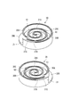
スクロール圧縮機10は、3Dタイプのスクロール圧縮機であり、双方のスクロール20,30間に形成される圧縮室Sの容積が渦巻きの途中でラップ21,31の高さ方向にも減少している。そのために、固定スクロール20および旋回スクロール30の双方において、図3に示すように、ラップ21,31の高さが外周側よりも内周側で低く、ラップ21,31に対向する相手側の端板300,200が内周側では外周側よりも内面側に突出している。
したがって、ラップ21,31の各々には、外周側から内周側へと低くなる段差部21C,31Cが形成されるとともに、端板300,200の各々には、外周側から内周側へと高くなる段差壁20C,30Cが形成される。段差壁20C,30Cは、端板200,300の平面視で円弧状に形成される。
したがって、ラップ21,31の各々には、外周側から内周側へと低くなる段差部21C,31Cが形成されるとともに、端板300,200の各々には、外周側から内周側へと高くなる段差壁20C,30Cが形成される。段差壁20C,30Cは、端板200,300の平面視で円弧状に形成される。
固定スクロール20のラップ21は、段差部21Cよりも内周側に位置する内周ラップ21Aと、段差部21Cよりも外周側に位置する外周ラップ21Bとに区分される。
ラップ21に対向する旋回端板300の底部は、段差壁30Cを境に内周底部30Aと外周底部30Bとに区分される。
また、旋回スクロール30のラップ31は、段差部31Cよりも内周側に位置する内周ラップ31Aと、段差部31Cよりも外周側に位置する外周ラップ31Bとに区分される。
ラップ31に対向する固定端板200の底部は、段差壁20Cを境に内周底部20Aと外周底部20Bとに区分される。
ラップ21に対向する旋回端板300の底部は、段差壁30Cを境に内周底部30Aと外周底部30Bとに区分される。
また、旋回スクロール30のラップ31は、段差部31Cよりも内周側に位置する内周ラップ31Aと、段差部31Cよりも外周側に位置する外周ラップ31Bとに区分される。
ラップ31に対向する固定端板200の底部は、段差壁20Cを境に内周底部20Aと外周底部20Bとに区分される。
以下、ラップ21およびラップ31の各々に設けられるチップシールについて説明する。
図3に示すように、固定スクロール20の内周ラップ21Aの先端には、内周チップシール41が設けられる。内周チップシール41は、内周ラップ21Aと旋回端板300の内周底部30Aとの間に介在する。内周チップシール41は、段差部21Cの付近に位置する内周ラップ21Aの始端から、渦巻きの中心部に位置する内周ラップ21Aの終端までのほぼ全体に亘って設けられる。
また、固定スクロール20の外周ラップ21Bの先端には、外周チップシール42が設けられる。外周チップシール42は、外周ラップ21Bと旋回端板300の外周底部30Bとの間に介在する。外周チップシール42は、渦巻きの最外周に位置する外周ラップ21Bの始端から、段差部21Cの付近に位置する外周ラップ21Bの終端までのほぼ全体に亘って設けられる。
本実施形態では、内周チップシール41および外周チップシール42が同じ厚みに形成される。
図3に示すように、固定スクロール20の内周ラップ21Aの先端には、内周チップシール41が設けられる。内周チップシール41は、内周ラップ21Aと旋回端板300の内周底部30Aとの間に介在する。内周チップシール41は、段差部21Cの付近に位置する内周ラップ21Aの始端から、渦巻きの中心部に位置する内周ラップ21Aの終端までのほぼ全体に亘って設けられる。
また、固定スクロール20の外周ラップ21Bの先端には、外周チップシール42が設けられる。外周チップシール42は、外周ラップ21Bと旋回端板300の外周底部30Bとの間に介在する。外周チップシール42は、渦巻きの最外周に位置する外周ラップ21Bの始端から、段差部21Cの付近に位置する外周ラップ21Bの終端までのほぼ全体に亘って設けられる。
本実施形態では、内周チップシール41および外周チップシール42が同じ厚みに形成される。
旋回スクロール30についても同様に、内周ラップ31Aの先端に、内周チップシール51が設けられる。内周チップシール51は、内周ラップ31Aと固定端板200の内周底部20Aとの間に介在する。内周チップシール51は、内周チップシール41と同様に形成される。
また、外周ラップ31Bの先端には、外周チップシール52が設けられる。外周チップシール52は、外周ラップ31Bと固定端板200の外周底部20Bとの間に介在する。外周チップシール52は、外周チップシール42と同様に形成される。
また、外周ラップ31Bの先端には、外周チップシール52が設けられる。外周チップシール52は、外周ラップ31Bと固定端板200の外周底部20Bとの間に介在する。外周チップシール52は、外周チップシール42と同様に形成される。
これらのチップシール41,42,51,52は、図4に示すように、それらが設けられるラップに形成されたシール溝Dに収容される。シール溝Dの各々において、内周側に位置するシール溝Dの内壁とチップシールとの間の間隙Gから、シール溝Dに沿って、チップシールの背面側に圧縮空気が導入される。このことによってチップシールの表面側の圧力が背面側よりも負圧となるので、チップシールはシール溝Dから浮上し、端板に押し付けられる。すると、チップシールと端板との隙間が封止されるので、圧縮室Sが気密に保たれる。
本実施形態は、内周チップシール41,51と、外周チップシール42,52との材質が相違することに特徴を有する。
内周チップシール41,51の材質および外周チップシール42,52の材質は、空気の圧縮に伴って上昇する温度および圧力に基づいて定められる。
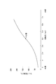
図5は、渦巻きの最外周(0rad)から渦巻きの中心部(最内周)に向かうにつれて、ラップ21,31の温度が上昇する様子を示す。
0radから2πradまでは、吸込口INが開いてから閉じられるまでの回転角に相当する。その回転角の範囲では、圧縮室S内がスクロール20,30の外部雰囲気下にあるため、温度が上昇し難い。図5に示す例では、最外周から2πradにおけるラップ21,31の温度は約50℃に留まる。
2πradを超えて圧縮室S内で圧縮が開始されると、圧縮による空気の温度上昇に伴ってラップ21,31の温度も上昇し、渦巻きの中心部(約7πrad)では225℃まで上昇する。
内周チップシール41,51の材質および外周チップシール42,52の材質は、空気の圧縮に伴って上昇する温度および圧力に基づいて定められる。
図5は、渦巻きの最外周(0rad)から渦巻きの中心部(最内周)に向かうにつれて、ラップ21,31の温度が上昇する様子を示す。
0radから2πradまでは、吸込口INが開いてから閉じられるまでの回転角に相当する。その回転角の範囲では、圧縮室S内がスクロール20,30の外部雰囲気下にあるため、温度が上昇し難い。図5に示す例では、最外周から2πradにおけるラップ21,31の温度は約50℃に留まる。
2πradを超えて圧縮室S内で圧縮が開始されると、圧縮による空気の温度上昇に伴ってラップ21,31の温度も上昇し、渦巻きの中心部(約7πrad)では225℃まで上昇する。
図5に示す温度は一例である。圧縮室Sの容積や圧縮比、ラップ21,31の最外周から最内周までの回転角に応じて温度や温度上昇の勾配が変わるが、いずれの場合も、最外周から2πまでは温度上昇が緩慢で、2πを超えて中心部に向かうにつれて次第に温度が上昇するのは同様である。
渦巻きの中心部を含むラップ21,31の内周側を受け持つ内周チップシール41,51には、上記のような高温に耐えることのできる耐熱性が必要とされる。
また、内周チップシール41,51は、外周チップシール42,52に比べて、圧縮空気による背圧が高いことから、端板に強く押し付けられて摺動するので、内周チップシール41,51と端板の間の摩擦力が大である。したがって、摩耗により内周チップシール41,51が早期に消耗するのを避けるために、内周チップシール41,51には耐摩耗性も必要とされる。
さらに、高温となる内周側を受け持ち、端板との間で摩擦熱も作用する内周チップシール41,51は熱膨張が大きい。そのため、内周チップシール41,51が端板により強く押し付けられると摩耗が顕著となる。摩耗量を少なくするために、内周チップシール41,51は線膨張係数が小さいことが望まれる。
ここで、内周チップシール41,51と外周チップシール42,52の間で背圧や熱膨張が違うために、内周チップシール41,51が端板300,200に押し付けられていても外周チップシール42,52と端板300,200との間には隙間が生じうる。これを避けるために、内周チップシール41,51の線膨張係数と、外周チップシール42,52の線膨張係数とのバランスをとることが好ましい。
また、内周チップシール41,51は、外周チップシール42,52に比べて、圧縮空気による背圧が高いことから、端板に強く押し付けられて摺動するので、内周チップシール41,51と端板の間の摩擦力が大である。したがって、摩耗により内周チップシール41,51が早期に消耗するのを避けるために、内周チップシール41,51には耐摩耗性も必要とされる。
さらに、高温となる内周側を受け持ち、端板との間で摩擦熱も作用する内周チップシール41,51は熱膨張が大きい。そのため、内周チップシール41,51が端板により強く押し付けられると摩耗が顕著となる。摩耗量を少なくするために、内周チップシール41,51は線膨張係数が小さいことが望まれる。
ここで、内周チップシール41,51と外周チップシール42,52の間で背圧や熱膨張が違うために、内周チップシール41,51が端板300,200に押し付けられていても外周チップシール42,52と端板300,200との間には隙間が生じうる。これを避けるために、内周チップシール41,51の線膨張係数と、外周チップシール42,52の線膨張係数とのバランスをとることが好ましい。
内周チップシール41,51の材質は、上記のような高温、高圧条件下での耐熱性および耐摩耗性を満足する樹脂または金属から選択される。
内周チップシール41,51に用いることのできる樹脂としては、例えば、PI(ポリイミド)、PEEK(ポリエーテルエーテルケトン)、PTFE(ポリテトラフルオロエチレン)などが挙げられる。その他、PAI(ポリアミドイミド)、PPS(ポリフェニレンサルファイド)なども採用できる。それらの樹脂に金属やカーボンなどのフィラーを混在させることもできる。
上記のような樹脂から、内周チップシール41,51を射出成形等により形成することができる。
また、内周チップシール41,51は、例えば、鉄などの金属から、プレス打ち抜きなどにより形成することもできる。
ここで、内周チップシール41,51の各々の材質が相違していてもよい。外周チップシール42,52についても同様である。
下記に、材質別の連続使用での耐熱温度、および線膨張係数を例示する。
PI(例) :240℃、1.7~4.5×10⁻⁵/℃
PEEK(例):260℃、3.0~5.7×10⁻⁵/℃
PTFE(例):260℃、8.3~15.2×10⁻⁵/℃
PAI(例) :250℃、4.0×10⁻⁵/℃
PPS(例) :230℃、1.8~8.7×10⁻⁵/℃
内周チップシール41,51に用いることのできる樹脂としては、例えば、PI(ポリイミド)、PEEK(ポリエーテルエーテルケトン)、PTFE(ポリテトラフルオロエチレン)などが挙げられる。その他、PAI(ポリアミドイミド)、PPS(ポリフェニレンサルファイド)なども採用できる。それらの樹脂に金属やカーボンなどのフィラーを混在させることもできる。
上記のような樹脂から、内周チップシール41,51を射出成形等により形成することができる。
また、内周チップシール41,51は、例えば、鉄などの金属から、プレス打ち抜きなどにより形成することもできる。
ここで、内周チップシール41,51の各々の材質が相違していてもよい。外周チップシール42,52についても同様である。
下記に、材質別の連続使用での耐熱温度、および線膨張係数を例示する。
PI(例) :240℃、1.7~4.5×10⁻⁵/℃
PEEK(例):260℃、3.0~5.7×10⁻⁵/℃
PTFE(例):260℃、8.3~15.2×10⁻⁵/℃
PAI(例) :250℃、4.0×10⁻⁵/℃
PPS(例) :230℃、1.8~8.7×10⁻⁵/℃
内周チップシール41,51に求められる耐熱性および耐摩耗性は、渦巻きの中心部における温度や圧力に応じて変わる。
図5に示す例では、内周チップシール41,51の耐熱温度が、240℃以上であることが好ましい。
図5に示す例では、内周チップシール41,51の耐熱温度が、240℃以上であることが好ましい。
一方、外周チップシール42,52は、空気が吸い込まれる最外周を含むラップ21,31の外周側を受け持つために、温度上昇が小さく、内周側よりも背圧が低いために押し付け荷重も小さい。そのため、外周チップシール42,52は、内周チップシール41,51に比べて、耐熱性および耐摩耗性が低くてもよく、線膨張係数が高くてもよい。
外周チップシール42,52に用いることのできる樹脂としては、例えば、PAI(ポリアミドイミド)、PPS(ポリフェニレンサルファイド)、PA(ポリアミド)などが挙げられる。その他、PTFE(ポリテトラフルオロエチレン)なども採用できる。
外周チップシール42,52は、鉄などの金属から形成することもできる。
外周チップシール42,52に用いることのできる樹脂としては、例えば、PAI(ポリアミドイミド)、PPS(ポリフェニレンサルファイド)、PA(ポリアミド)などが挙げられる。その他、PTFE(ポリテトラフルオロエチレン)なども採用できる。
外周チップシール42,52は、鉄などの金属から形成することもできる。
本実施形態では、内周チップシール41,51および外周チップシール42,52に必要な耐熱性、耐摩耗性、および両者の熱膨張のバランスを満たす限りにおいて、内周チップシール41,51を、外周チップシール42,52の材質よりも、耐熱温度が高いこと、比摩耗量が小さいこと、および線膨張係数が小さいことの少なくとも一の要件を満たす材質から形成する。
したがって、内周チップシール41,51および外周チップシール42,52の両者は、耐熱温度が同程度で、比摩耗量または線膨張係数が相違する材質から形成されていてもよい。
あるいは、両者が、比摩耗量が同程度で、耐熱温度または線膨張係数が相違する材質から形成されていたり、線膨張係数が同程度で、耐熱温度または比摩耗量が相違する材質から形成されていてもよい。
ここで、内周チップシール41,51に使用可能な材質と、外周チップシール42,52に使用可能な材質との組み合わせ例を2つだけ示す。
(1)内周チップシールの材質:PI、外周チップシールの材質:PPS
(2)内周チップシールの材質:鉄系金属、外周チップシールの材質:PA
したがって、内周チップシール41,51および外周チップシール42,52の両者は、耐熱温度が同程度で、比摩耗量または線膨張係数が相違する材質から形成されていてもよい。
あるいは、両者が、比摩耗量が同程度で、耐熱温度または線膨張係数が相違する材質から形成されていたり、線膨張係数が同程度で、耐熱温度または比摩耗量が相違する材質から形成されていてもよい。
ここで、内周チップシール41,51に使用可能な材質と、外周チップシール42,52に使用可能な材質との組み合わせ例を2つだけ示す。
(1)内周チップシールの材質:PI、外周チップシールの材質:PPS
(2)内周チップシールの材質:鉄系金属、外周チップシールの材質:PA
本実施形態では、内周チップシール41,51には、渦巻きの中心部における高温および高圧から導かれる耐久性を持たせつつ、外周チップシール42,52には、必要な耐熱性および耐摩耗性を満たす限りにおいて、内周チップシール41,51の材質よりも安価な材質を用いる。
ここで、チップシールの耐久性向上、およびコスト低減の両者をバランスよく実現するために、内周チップシール41,51および外周チップシール42,52を隔てる段差部21C,31Cの位置を設定する。
段差部21C,31Cの位置は、内周ラップ21Aから外周ラップ21Bが立ち上がる箇所のことを言うものとする。
ここで、チップシールの耐久性向上、およびコスト低減の両者をバランスよく実現するために、内周チップシール41,51および外周チップシール42,52を隔てる段差部21C,31Cの位置を設定する。
段差部21C,31Cの位置は、内周ラップ21Aから外周ラップ21Bが立ち上がる箇所のことを言うものとする。
段差部21C,31Cの位置を定めるにあたり、本実施形態では2つの指標を用いる。第1の指標は、ラップ21,31の温度が上昇する温度域の中心値に対応する角度である。第2の指標は、旋回スクロール30が一回転するときの回転角である2πradである。
図5の例において、ラップ21,31の温度域は、0radにおける25℃から約7πradにおける225℃までであり、その中心値は125℃である。中心値125℃に対応する回転角は4πradである(第1の指標)。
また、一回転に対応する2πrad(第2の指標)は、ラップ21,31の最外周に吸込口INが開いてから閉じられるまでの回転角に対応する。この2πradは、外周チップシール42,52に安価な材質を選択することによるコスト低減効果を確実に得るために用いられる。
図5の例において、ラップ21,31の温度域は、0radにおける25℃から約7πradにおける225℃までであり、その中心値は125℃である。中心値125℃に対応する回転角は4πradである(第1の指標)。
また、一回転に対応する2πrad(第2の指標)は、ラップ21,31の最外周に吸込口INが開いてから閉じられるまでの回転角に対応する。この2πradは、外周チップシール42,52に安価な材質を選択することによるコスト低減効果を確実に得るために用いられる。
上記の第1、第2の指標を用いて、段差部21C,31Cの位置は、ラップ21,31の最外周から内周側へ2πrad以上、4πrad以下の範囲に設定することが好ましい。
ここで、4πrad以下であれば、外周チップシール42,52の耐熱温度を上昇温度域の中心値以下の温度に抑えられる。
また、段差部21C,31Cが最外周から2πを超えた位置にあれば、外周チップシール42,52の長さを2πrad以上に確保することができる。そうすると、外周チップシール42,52に安価な材料を選ぶことによるコスト低減効果を確実に得ることができる。
以上を踏まえて、本実施形態では、段差部21C,31Cの位置を2πに設定しているが、ラップ21,31の最外周から2πrad以上、4πrad以下の範囲の任意の位置に段差部21C,31Cを設けることができる。
ここで、段差部21C,31Cの位置が最外周から内周側へ3πrad以上であれば、吸込口INが閉じて圧縮室S内が締め切られるときに、圧縮室S内に段差部21C,31Cが存在しない。圧縮室Sは、端板200,300間の寸法が一様の空間となり、ラップ21,31の高さ方向には容積が減少しない。そのため、最外周に位置する圧縮室Sの容積を最大に確保できるので、圧縮比を大きく確保できる。
なお、段差部21C,31Cの位置には、スクロール20,30の寸法誤差や組付誤差による若干の誤差が許容される。
ここで、4πrad以下であれば、外周チップシール42,52の耐熱温度を上昇温度域の中心値以下の温度に抑えられる。
また、段差部21C,31Cが最外周から2πを超えた位置にあれば、外周チップシール42,52の長さを2πrad以上に確保することができる。そうすると、外周チップシール42,52に安価な材料を選ぶことによるコスト低減効果を確実に得ることができる。
以上を踏まえて、本実施形態では、段差部21C,31Cの位置を2πに設定しているが、ラップ21,31の最外周から2πrad以上、4πrad以下の範囲の任意の位置に段差部21C,31Cを設けることができる。
ここで、段差部21C,31Cの位置が最外周から内周側へ3πrad以上であれば、吸込口INが閉じて圧縮室S内が締め切られるときに、圧縮室S内に段差部21C,31Cが存在しない。圧縮室Sは、端板200,300間の寸法が一様の空間となり、ラップ21,31の高さ方向には容積が減少しない。そのため、最外周に位置する圧縮室Sの容積を最大に確保できるので、圧縮比を大きく確保できる。
なお、段差部21C,31Cの位置には、スクロール20,30の寸法誤差や組付誤差による若干の誤差が許容される。
以上で説明した本実施形態では、3Dタイプのスクロール圧縮機10において、ラップ21,31の段差部21C,31Cで隔てられ、分離した内周チップシール41,51および外周チップシール42,52のうち、内周チップシール41,51の材質を渦巻きの中心部における高温および高圧から導かれる材質で形成しつつ、外周チップシール42,52を安価な材質から形成する。
したがって、チップシールに溶損、異常摩耗、焼き付きなどを生じさせることなく、ラップ21,31と端板300,200との間が封止された状態を維持し、スクロール圧縮機10の信頼性を確保することができるとともに、コスト低減にも寄与できる。
したがって、チップシールに溶損、異常摩耗、焼き付きなどを生じさせることなく、ラップ21,31と端板300,200との間が封止された状態を維持し、スクロール圧縮機10の信頼性を確保することができるとともに、コスト低減にも寄与できる。
〔第2実施形態〕
次に、図6を参照し、本発明の第2実施形態について説明する。
第2実施形態は、第1実施形態との相違点を中心に説明する。第1実施形態と同様の構成には同じ符号を付している。
第2実施形態では、内周チップシール41,51の材質を外周チップシール42,52の材質と異ならせる代わりに、内周チップシール41,51に耐摩耗性を有する材質のコーティングを施す。
次に、図6を参照し、本発明の第2実施形態について説明する。
第2実施形態は、第1実施形態との相違点を中心に説明する。第1実施形態と同様の構成には同じ符号を付している。
第2実施形態では、内周チップシール41,51の材質を外周チップシール42,52の材質と異ならせる代わりに、内周チップシール41,51に耐摩耗性を有する材質のコーティングを施す。
図6に示すように、内周チップシール41は、表面に、耐摩耗性のコーティング45を備える。コーティング45の材質としては、例えば、PTFE(ポリテトラフルオロエチレン)、PEEK(ポリエーテルエーテルケトン)、DLC(ダイヤモンドライクカーボン)、TiN(窒化チタン)、およびCrN(窒化クロム)などを用いることができる。
コーティング45の耐摩耗性は、渦巻きの中心部における圧力に応じて適宜設定する。
コーティング45の耐摩耗性は、渦巻きの中心部における圧力に応じて適宜設定する。
コーティング45の膜厚は、コーティング45に求められる比摩耗量に応じて設定することができる。
コーティング45は、内周チップシール41において少なくとも、端板300の内周底部30Aに対向する面45S(表面)を構成しており、相手側の端板300に対向する。内周チップシール41の端板300に対向する部分(コーティング45)の材質は、コーティングが施されない外周チップシール42の端板300に対向する部分の材質とは相違する。
内周チップシール51も、内周チップシール41と同様のコーティング45を施すことができる。
コーティング45は、内周チップシール41において少なくとも、端板300の内周底部30Aに対向する面45S(表面)を構成しており、相手側の端板300に対向する。内周チップシール41の端板300に対向する部分(コーティング45)の材質は、コーティングが施されない外周チップシール42の端板300に対向する部分の材質とは相違する。
内周チップシール51も、内周チップシール41と同様のコーティング45を施すことができる。
PTFE、PEEKのコーティング45は、樹脂の粉体を溶液に混合した液状物をエアスプレーガンで内周チップシール41,51(基材)に吹き付けて塗装し、樹脂の融点温度以上で加熱して溶着させることで形成することができる。所定の膜厚となるまで、塗装、加熱が繰り返される。このようなエアスプレー方式の他、静電気を用いて樹脂の粉体を基材に塗装する静電粉体塗装方式、浸漬(ディップ)方式などもあるが、いずれにしても、熱を加えて樹脂を基材に溶着させる。
DLCのコーティング45は、プラズマ化学気相成長(PECVD;plasma-enhanced chemical vapor deposition)法や物理気相成長(PVD;Physical Vapor Deposition)法により形成することができる。
TiN、CrNのコーティング45は、PVD法により形成することができる。
DLCのコーティング45は、プラズマ化学気相成長(PECVD;plasma-enhanced chemical vapor deposition)法や物理気相成長(PVD;Physical Vapor Deposition)法により形成することができる。
TiN、CrNのコーティング45は、PVD法により形成することができる。
コーティング45が成膜される内周チップシール41,51の基材の材質は、コーティング45の形成過程で加えられる熱により溶けないものが選択される。
内周チップシール41,51の基材は、外周チップシール42,52と同じ材質とすることができる。
内周チップシール41,51の基材は、外周チップシール42,52と同じ材質とすることができる。
本実施形態では、内周チップシール41,51にコーティング45を施すことにより、内周チップシール41,51に外周チップシール42,52よりも高い耐摩耗性を持たせることができる。したがって、内周チップシール41,51の基材の材質を外周チップシール42,52の材質と同じとすることで材料費を抑えながら、必要な耐摩耗性を実現できる。
また、厚みやコストの点でチップシールの基材の材質に使用することが難しくても、基材に使用可能な材質よりも耐摩耗性に優れた材質をコーティング45の材質に選択することにより、耐摩耗性を一層向上させることができる。
さらに、コーティング45を施すことにより、基材の表面よりも滑らかな表面が得られれば、内周チップシール41,51の表面の摩擦係数が小さくなる。上記に例示したコーティング45の材質の中で、例えばDLCの摩擦係数は0.1程度(乾燥条件)である。摩擦係数が小さいために摩耗量が減る点でも、耐摩耗性を高くすることができる。
また、厚みやコストの点でチップシールの基材の材質に使用することが難しくても、基材に使用可能な材質よりも耐摩耗性に優れた材質をコーティング45の材質に選択することにより、耐摩耗性を一層向上させることができる。
さらに、コーティング45を施すことにより、基材の表面よりも滑らかな表面が得られれば、内周チップシール41,51の表面の摩擦係数が小さくなる。上記に例示したコーティング45の材質の中で、例えばDLCの摩擦係数は0.1程度(乾燥条件)である。摩擦係数が小さいために摩耗量が減る点でも、耐摩耗性を高くすることができる。
第2実施形態において、内周チップシール41,51の基材が外周チップシール42,52の材質とは異なる材質から形成されていてもよい。
また、外周チップシール42,52に、内周チップシール41,51に施されるコーティング45とは異なる材質のコーティングを施すことも許容される。
また、外周チップシール42,52に、内周チップシール41,51に施されるコーティング45とは異なる材質のコーティングを施すことも許容される。
〔第3実施形態〕
次に、図7を参照し、本発明の第3実施形態について説明する。第3実施形態でも、第1実施形態との相違点を中心に説明し、既に説明した構成と同様の構成には同じ符号を付す。
第3実施形態では、内周チップシールおよび外周チップシールの両者の厚みが相違する。内周チップシールおよび外周チップシールの両者の材質は同じである。
次に、図7を参照し、本発明の第3実施形態について説明する。第3実施形態でも、第1実施形態との相違点を中心に説明し、既に説明した構成と同様の構成には同じ符号を付す。
第3実施形態では、内周チップシールおよび外周チップシールの両者の厚みが相違する。内周チップシールおよび外周チップシールの両者の材質は同じである。
図7に示すように、内周ラップ21Aに設けられる内周チップシール61と、外周ラップ21Bに設けられる外周チップシール42との各々の厚みは相違する。なお、内周ラップ31Aに設けられる内周チップシールは、内周チップシール61と同様に形成されており、外周ラップ31Bに設けられる外周チップシールも、外周チップシール42と同様に形成される。
シール溝Dの深さ方向において、外周チップシール42の厚みはT1に設定される。この厚みは、第1実施形態および第2実施形態における外周チップシール42の厚みと同様である。
内周チップシール61の厚みT2は、外周チップシール42の厚みT1よりも大きい。
シール溝Dの深さ方向において、外周チップシール42の厚みはT1に設定される。この厚みは、第1実施形態および第2実施形態における外周チップシール42の厚みと同様である。
内周チップシール61の厚みT2は、外周チップシール42の厚みT1よりも大きい。
内周チップシール61が厚いと、内周チップシール61が大きく摩耗したとしても、封止に足りる厚みを残すことができる。これにより、チップシールの信頼性を確保できる。
また、外周チップシール42の厚みT1を封止に足りる程度の厚みに維持できるので、コストを抑えることができる。
また、外周チップシール42の厚みT1を封止に足りる程度の厚みに維持できるので、コストを抑えることができる。
第3実施形態は、第1実施形態または第2実施形態と組み合わせることもできる。つまり、第3実施形態において、内周チップシール41,51および外周チップシール42,52の両者が異なる材質から形成されていたり、内周チップシール41,51にコーティング45が施されていてもよい。
以上で説明した第1~第3実施形態のいずれの構成によっても、ラップの内周側での高温や高圧に耐える耐久性を内周チップシールに与えることができるので、スクロール圧縮機の信頼性を向上させることができる。
ここで、空気を圧縮するスクロール圧縮機10は、一般に圧縮比が高く、渦巻きの中心部における昇温が顕著となるので、第1~第3実施形態の各々の構成によって内周チップシールに耐久性を持たせることは、空気圧縮のスクロール圧縮機において効果が大きい。
その上、スクロール圧縮機10のようにオイルフリーとされていると、オイルによる冷却の作用が得られない分、尚更、内周側における昇温が顕著となる。しかも、オイルによる潤滑作用も得られず、チップシールが潤滑油を介さずに直接、端板に対して摺動されるために摩耗し易い。そのため、空気圧縮でかつオイルフリーのスクロール圧縮機に本発明を適用すると、本発明の効果が際立つ。
なお、冷媒を圧縮するスクロール圧縮機でも、大型の冷凍庫や空気調和機に用いるスクロール圧縮機のように、渦巻きの中心部において空気圧縮と同程度に高温、高圧縮比となる場合がある。その場合にも本発明の効果が大きい。そのように冷媒圧縮するものでオイルフリーのスクロール圧縮機においても、本発明の効果が際立つ。
ここで、空気を圧縮するスクロール圧縮機10は、一般に圧縮比が高く、渦巻きの中心部における昇温が顕著となるので、第1~第3実施形態の各々の構成によって内周チップシールに耐久性を持たせることは、空気圧縮のスクロール圧縮機において効果が大きい。
その上、スクロール圧縮機10のようにオイルフリーとされていると、オイルによる冷却の作用が得られない分、尚更、内周側における昇温が顕著となる。しかも、オイルによる潤滑作用も得られず、チップシールが潤滑油を介さずに直接、端板に対して摺動されるために摩耗し易い。そのため、空気圧縮でかつオイルフリーのスクロール圧縮機に本発明を適用すると、本発明の効果が際立つ。
なお、冷媒を圧縮するスクロール圧縮機でも、大型の冷凍庫や空気調和機に用いるスクロール圧縮機のように、渦巻きの中心部において空気圧縮と同程度に高温、高圧縮比となる場合がある。その場合にも本発明の効果が大きい。そのように冷媒圧縮するものでオイルフリーのスクロール圧縮機においても、本発明の効果が際立つ。
また、第1~第3実施形態のスクロール圧縮機では、段差部がラップの周方向の1箇所にだけ設けられるが、ラップの周方向の複数箇所に段差部を設けることもできる。
例えば、図8に示すように、ラップ21の周方向の2箇所に段差部211,212が設けられていれば、最内周(渦巻きの中心部)を含む位置に設けられる最内周チップシール71と、最外周を含む位置に設けられる最外周チップシール73と、中間の位置に設けられる中間チップシール72とが存在する。
この場合、2箇所の段差部211,212のうち外周側に位置するものを第1段差部211、内周側に位置するものを第2段差部212と呼ぶと、第1段差部211を基準として、第1段差部211よりも内周側に位置する中間チップシール72および最内周チップシール71と、第1段差部211よりも外周側に位置する最外周チップシール73との間で材質、あるいは厚みを異ならせることができる。
あるいは、第2段差部212を基準として、第2段差部212よりも内周側に位置する最内周チップシール71と、第2段差部212よりも外周側に位置する中間チップシール72および最外周チップシール73との間で材質、あるいは厚みを異ならせることができる。
さらには、最外周チップシール73、中間チップシール72、および最内周チップシール71の各々の材質または厚みを段階的に異ならせることもできる。
つまり、第1段差部211よりも内周側に位置する中間チップシール72と、第1段差部211よりも外周側に位置する最外周チップシール73とで材質、あるいは厚みを異ならせるとともに、第2段差部212よりも内周側に位置する最内周チップシール71と、第2段差部212よりも外周側に位置する中間チップシール72とで材質、あるいは厚みを異ならせることができる。
いずれにしても、ラップの最外周から最内周に向けて気体の温度および圧力が上昇するために、より内周側ではより高温、高圧となることから、相対的により内周側に位置する内周チップシールの材質を相対的に外周側に位置する外周チップシールに比べて耐熱性、耐摩耗性に優れたものとし、また、内周チップシールの厚みを外周チップシールに比べて厚くすればよい。
例えば、図8に示すように、ラップ21の周方向の2箇所に段差部211,212が設けられていれば、最内周(渦巻きの中心部)を含む位置に設けられる最内周チップシール71と、最外周を含む位置に設けられる最外周チップシール73と、中間の位置に設けられる中間チップシール72とが存在する。
この場合、2箇所の段差部211,212のうち外周側に位置するものを第1段差部211、内周側に位置するものを第2段差部212と呼ぶと、第1段差部211を基準として、第1段差部211よりも内周側に位置する中間チップシール72および最内周チップシール71と、第1段差部211よりも外周側に位置する最外周チップシール73との間で材質、あるいは厚みを異ならせることができる。
あるいは、第2段差部212を基準として、第2段差部212よりも内周側に位置する最内周チップシール71と、第2段差部212よりも外周側に位置する中間チップシール72および最外周チップシール73との間で材質、あるいは厚みを異ならせることができる。
さらには、最外周チップシール73、中間チップシール72、および最内周チップシール71の各々の材質または厚みを段階的に異ならせることもできる。
つまり、第1段差部211よりも内周側に位置する中間チップシール72と、第1段差部211よりも外周側に位置する最外周チップシール73とで材質、あるいは厚みを異ならせるとともに、第2段差部212よりも内周側に位置する最内周チップシール71と、第2段差部212よりも外周側に位置する中間チップシール72とで材質、あるいは厚みを異ならせることができる。
いずれにしても、ラップの最外周から最内周に向けて気体の温度および圧力が上昇するために、より内周側ではより高温、高圧となることから、相対的により内周側に位置する内周チップシールの材質を相対的に外周側に位置する外周チップシールに比べて耐熱性、耐摩耗性に優れたものとし、また、内周チップシールの厚みを外周チップシールに比べて厚くすればよい。
上記以外にも、本発明の主旨を逸脱しない限り、上記実施形態で挙げた構成を取捨選択したり、他の構成に適宜変更することが可能である。
本発明のスクロール圧縮機は、モータの回転力を動力とするものには限られず、エンジンからベルトを介してシャフトに伝達される駆動力を動力とするものであってもよい。
本発明のスクロール圧縮機は、モータの回転力を動力とするものには限られず、エンジンからベルトを介してシャフトに伝達される駆動力を動力とするものであってもよい。
10 スクロール圧縮機
11 モータ
12 モータケース
13 出力軸
14 カップリング
15 シャフト
20 固定スクロール
20A 内周底部
20B 外周底部
20C 段差壁
21 ラップ
21A 内周ラップ
21B 外周ラップ
21C 段差部
30 旋回スクロール
30A 内周底部
30B 外周底部
30C 段差壁
31 ラップ
31A 内周ラップ
31B 外周ラップ
31C 段差部
34 ボス
41 内周チップシール
42 外周チップシール
45 コーティング
45S 対向する面
51 内周チップシール
52 外周チップシール
61 内周チップシール
151 偏心ピン
200 固定端板
201 吐出ポート
300 旋回端板
D シール溝
G 間隙
IN 吸込口
S 圧縮室
T1,T2 厚み寸法
11 モータ
12 モータケース
13 出力軸
14 カップリング
15 シャフト
20 固定スクロール
20A 内周底部
20B 外周底部
20C 段差壁
21 ラップ
21A 内周ラップ
21B 外周ラップ
21C 段差部
30 旋回スクロール
30A 内周底部
30B 外周底部
30C 段差壁
31 ラップ
31A 内周ラップ
31B 外周ラップ
31C 段差部
34 ボス
41 内周チップシール
42 外周チップシール
45 コーティング
45S 対向する面
51 内周チップシール
52 外周チップシール
61 内周チップシール
151 偏心ピン
200 固定端板
201 吐出ポート
300 旋回端板
D シール溝
G 間隙
IN 吸込口
S 圧縮室
T1,T2 厚み寸法
Claims (8)
- 固定スクロールおよび旋回スクロールを備え、前記固定スクロールおよび前記旋回スクロールがいずれも、外周側から内周側へと段差部を経て高さが低くなる渦巻状のラップと、相手側の前記ラップの前記段差部に倣って立ち上がる段差壁が形成される端板と、を有するスクロール圧縮機であって、
前記段差部よりも内周側に設けられて相手側の前記端板との間に介在する内周チップシールと、前記段差部よりも外周側に設けられて相手側の前記端板との間に介在する外周チップシールとは、少なくとも前記端板に対向する部分の材質が相違する、
ことを特徴とするスクロール圧縮機。 - 前記段差部は、
前記ラップの最外周の回転角から前記ラップの最内周の回転角までの間に前記ラップの温度が上昇する温度域の中心値をとる回転角よりも外周側に位置し、
前記内周チップシールは、
前記外周チップシールの材質よりも、耐熱温度が高いこと、比摩耗量が小さいこと、および線膨張係数が小さいことの少なくとも一の要件を満たす材質から形成される、
請求項1に記載のスクロール圧縮機。 - 前記段差部は、
前記ラップの最外周の回転角から前記ラップの最内周の回転角までの間に前記ラップの温度が上昇する温度域の中心値をとる回転角よりも外周側に位置し、
前記内周チップシールの少なくとも前記端板に対向する部分は、耐摩耗性を有する材質のコーティングから構成される、
請求項1または2に記載のスクロール圧縮機。 - 前記段差部は、
前記ラップの最外周の回転角から前記ラップの最内周の回転角までの間に前記ラップの温度が上昇する温度域の中心値をとる回転角よりも外周側に位置し、
前記内周チップシールの厚み寸法は、前記外周チップシールの厚み寸法よりも大きい、
請求項1から3のいずれか一項に記載のスクロール圧縮機。 - 固定スクロールおよび旋回スクロールを備え、前記固定スクロールおよび前記旋回スクロールがいずれも、外周側から内周側へと段差部を経て高さが低くなる渦巻状のラップと、相手側の前記ラップの前記段差部に倣って立ち上がる段差壁が形成される端板と、を有するスクロール圧縮機であって、
前記段差部よりも内周側に設けられて相手側の前記端板との間に介在する内周チップシールの厚み寸法は、前記段差部よりも外周側に設けられて相手側の前記端板との間に介在する外周チップシールの厚み寸法よりも大きい、
ことを特徴とするスクロール圧縮機。 - 前記段差部は、
前記ラップの最外周の回転角から内周側へ2πを超える回転角領域に位置する、
請求項1から5のいずれか一項に記載のスクロール圧縮機。 - 前記固定スクロールおよび前記旋回スクロールによって空気が圧縮される、
請求項1から6のいずれか一項に記載のスクロール圧縮機。 - 前記内周チップシールおよび前記外周チップシールは、潤滑油を介さずに直接、前記端板に対して摺動される、
請求項1から7のいずれか一項に記載のスクロール圧縮機。
Priority Applications (1)
| Application Number | Priority Date | Filing Date | Title |
|---|---|---|---|
| EP14830230.0A EP2998585B1 (en) | 2013-07-25 | 2014-06-24 | Scroll compressor |
Applications Claiming Priority (2)
| Application Number | Priority Date | Filing Date | Title |
|---|---|---|---|
| JP2013154204A JP6214954B2 (ja) | 2013-07-25 | 2013-07-25 | スクロール圧縮機 |
| JP2013-154204 | 2013-07-25 |
Publications (1)
| Publication Number | Publication Date |
|---|---|
| WO2015011875A1 true WO2015011875A1 (ja) | 2015-01-29 |
Family
ID=52392943
Family Applications (1)
| Application Number | Title | Priority Date | Filing Date |
|---|---|---|---|
| PCT/JP2014/003372 Ceased WO2015011875A1 (ja) | 2013-07-25 | 2014-06-24 | スクロール圧縮機 |
Country Status (3)
| Country | Link |
|---|---|
| EP (1) | EP2998585B1 (ja) |
| JP (1) | JP6214954B2 (ja) |
| WO (1) | WO2015011875A1 (ja) |
Cited By (3)
| Publication number | Priority date | Publication date | Assignee | Title |
|---|---|---|---|---|
| JPWO2017033546A1 (ja) * | 2015-08-25 | 2018-06-14 | 村田機械株式会社 | パージ装置、パージストッカ、及びパージ方法 |
| JP2018517097A (ja) * | 2015-04-23 | 2018-06-28 | エマソン クライメット テクノロジーズ(スーチョウ)カンパニー、リミテッド | スクロール圧縮機並びにスクロール圧縮機のための駆動軸及びアンロード・ブッシュ |
| WO2018124008A1 (ja) * | 2016-12-28 | 2018-07-05 | ナブテスコ株式会社 | スクロール式流体機械および車両 |
Families Citing this family (4)
| Publication number | Priority date | Publication date | Assignee | Title |
|---|---|---|---|---|
| JP6532713B2 (ja) * | 2015-03-12 | 2019-06-19 | 三菱重工サーマルシステムズ株式会社 | スクロール圧縮機 |
| JP2019073988A (ja) * | 2017-10-12 | 2019-05-16 | アネスト岩田株式会社 | スクロール流体機械ユニット |
| DE102020134469A1 (de) * | 2020-12-21 | 2022-06-23 | OET GmbH | Scrollverdichter zur Erzeugung von ölfreier Druckluft |
| EP4032764A1 (en) * | 2021-01-25 | 2022-07-27 | ZF CV Systems Global GmbH | Central air supply |
Citations (9)
| Publication number | Priority date | Publication date | Assignee | Title |
|---|---|---|---|---|
| JPH02124201U (ja) | 1989-03-27 | 1990-10-12 | ||
| JPH06323101A (ja) * | 1993-05-12 | 1994-11-22 | Daikin Ind Ltd | スクロール流体機械 |
| JPH07158568A (ja) * | 1993-12-09 | 1995-06-20 | Hitachi Ltd | スクロール流体機械 |
| JP2003106269A (ja) * | 2001-09-28 | 2003-04-09 | Anest Iwata Corp | スクロール流体機械 |
| JP2009074461A (ja) * | 2007-09-21 | 2009-04-09 | Mitsubishi Heavy Ind Ltd | スクロール圧縮機 |
| JP2010275895A (ja) * | 2009-05-27 | 2010-12-09 | Mitsubishi Heavy Ind Ltd | スクロール圧縮機 |
| JP2011144801A (ja) | 2009-12-15 | 2011-07-28 | Mitsubishi Heavy Ind Ltd | スクロール圧縮機 |
| JP2013501887A (ja) * | 2009-08-14 | 2013-01-17 | エドワーズ リミテッド | スクロール型ポンプ |
| JP2013160147A (ja) * | 2012-02-06 | 2013-08-19 | Mitsubishi Heavy Ind Ltd | スクロール型圧縮機 |
Family Cites Families (1)
| Publication number | Priority date | Publication date | Assignee | Title |
|---|---|---|---|---|
| JP4395325B2 (ja) * | 2003-05-21 | 2010-01-06 | 三菱重工業株式会社 | 段付き構造スクロール流体機械 |
-
2013
- 2013-07-25 JP JP2013154204A patent/JP6214954B2/ja active Active
-
2014
- 2014-06-24 EP EP14830230.0A patent/EP2998585B1/en active Active
- 2014-06-24 WO PCT/JP2014/003372 patent/WO2015011875A1/ja not_active Ceased
Patent Citations (9)
| Publication number | Priority date | Publication date | Assignee | Title |
|---|---|---|---|---|
| JPH02124201U (ja) | 1989-03-27 | 1990-10-12 | ||
| JPH06323101A (ja) * | 1993-05-12 | 1994-11-22 | Daikin Ind Ltd | スクロール流体機械 |
| JPH07158568A (ja) * | 1993-12-09 | 1995-06-20 | Hitachi Ltd | スクロール流体機械 |
| JP2003106269A (ja) * | 2001-09-28 | 2003-04-09 | Anest Iwata Corp | スクロール流体機械 |
| JP2009074461A (ja) * | 2007-09-21 | 2009-04-09 | Mitsubishi Heavy Ind Ltd | スクロール圧縮機 |
| JP2010275895A (ja) * | 2009-05-27 | 2010-12-09 | Mitsubishi Heavy Ind Ltd | スクロール圧縮機 |
| JP2013501887A (ja) * | 2009-08-14 | 2013-01-17 | エドワーズ リミテッド | スクロール型ポンプ |
| JP2011144801A (ja) | 2009-12-15 | 2011-07-28 | Mitsubishi Heavy Ind Ltd | スクロール圧縮機 |
| JP2013160147A (ja) * | 2012-02-06 | 2013-08-19 | Mitsubishi Heavy Ind Ltd | スクロール型圧縮機 |
Non-Patent Citations (1)
| Title |
|---|
| See also references of EP2998585A4 * |
Cited By (6)
| Publication number | Priority date | Publication date | Assignee | Title |
|---|---|---|---|---|
| JP2018517097A (ja) * | 2015-04-23 | 2018-06-28 | エマソン クライメット テクノロジーズ(スーチョウ)カンパニー、リミテッド | スクロール圧縮機並びにスクロール圧縮機のための駆動軸及びアンロード・ブッシュ |
| JPWO2017033546A1 (ja) * | 2015-08-25 | 2018-06-14 | 村田機械株式会社 | パージ装置、パージストッカ、及びパージ方法 |
| WO2018124008A1 (ja) * | 2016-12-28 | 2018-07-05 | ナブテスコ株式会社 | スクロール式流体機械および車両 |
| CN110073106A (zh) * | 2016-12-28 | 2019-07-30 | 纳博特斯克有限公司 | 涡旋式流体机械和车辆 |
| JPWO2018124008A1 (ja) * | 2016-12-28 | 2019-10-31 | ナブテスコ株式会社 | スクロール式流体機械および車両 |
| CN110073106B (zh) * | 2016-12-28 | 2022-01-28 | 纳博特斯克有限公司 | 涡旋式流体机械和车辆 |
Also Published As
| Publication number | Publication date |
|---|---|
| EP2998585A1 (en) | 2016-03-23 |
| EP2998585B1 (en) | 2017-04-26 |
| JP6214954B2 (ja) | 2017-10-18 |
| JP2015025387A (ja) | 2015-02-05 |
| EP2998585A4 (en) | 2016-07-20 |
Similar Documents
| Publication | Publication Date | Title |
|---|---|---|
| WO2015011875A1 (ja) | スクロール圧縮機 | |
| CN104662199B (zh) | 用于压缩机磨损表面的抗磨损涂层 | |
| CN103069166B (zh) | 制冷剂压缩机 | |
| AU2005205262B2 (en) | Fluid Machinery | |
| CN104074753A (zh) | 制冷剂压缩机 | |
| US8186982B2 (en) | Adjustable rotary pump with reduced wear | |
| JP4514493B2 (ja) | スクロール型流体機械 | |
| KR20170029313A (ko) | 스크롤 압축기 | |
| CN209654237U (zh) | 用于涡旋压缩机的聚合物复合材料插入部件 | |
| US10968912B2 (en) | Scroll compressor | |
| JP2013015092A (ja) | 圧縮機 | |
| CN101133126A (zh) | 滑动部件用组合物、滑动部件以及流体机械 | |
| WO2015025416A1 (ja) | 回転機械及び冷凍サイクル機器 | |
| JPH11107953A (ja) | 流体圧縮機 | |
| JP2009287483A (ja) | 冷媒圧縮機 | |
| JP2007224767A (ja) | 回転式流体機械 | |
| JP2005325842A (ja) | 流体機械 | |
| JP2022542034A (ja) | スクロールポンプ | |
| JP7824736B2 (ja) | スクロールコンプレッサの環状シール部材 | |
| JP2003035284A (ja) | スクロール型ポンプの部材の表面被覆方法 | |
| WO2022054364A1 (ja) | 摺動部材およびそれを用いた圧縮機および冷凍装置 | |
| JP2008144678A (ja) | スクロール圧縮機 | |
| JP2021014811A (ja) | スクロール型流体機械 | |
| JP2004076685A (ja) | スクロール形流体機械 |
Legal Events
| Date | Code | Title | Description |
|---|---|---|---|
| 121 | Ep: the epo has been informed by wipo that ep was designated in this application |
Ref document number: 14830230 Country of ref document: EP Kind code of ref document: A1 |
|
| DPE1 | Request for preliminary examination filed after expiration of 19th month from priority date (pct application filed from 20040101) | ||
| REEP | Request for entry into the european phase |
Ref document number: 2014830230 Country of ref document: EP |
|
| WWE | Wipo information: entry into national phase |
Ref document number: 2014830230 Country of ref document: EP |
|
| NENP | Non-entry into the national phase |
Ref country code: DE |