WO2015011875A1 - Compresseur à volute - Google Patents
Compresseur à volute Download PDFInfo
- Publication number
- WO2015011875A1 WO2015011875A1 PCT/JP2014/003372 JP2014003372W WO2015011875A1 WO 2015011875 A1 WO2015011875 A1 WO 2015011875A1 JP 2014003372 W JP2014003372 W JP 2014003372W WO 2015011875 A1 WO2015011875 A1 WO 2015011875A1
- Authority
- WO
- WIPO (PCT)
- Prior art keywords
- tip seal
- wrap
- end plate
- scroll
- rotation angle
- Prior art date
- Legal status (The legal status is an assumption and is not a legal conclusion. Google has not performed a legal analysis and makes no representation as to the accuracy of the status listed.)
- Ceased
Links
Images


Classifications
-
- F—MECHANICAL ENGINEERING; LIGHTING; HEATING; WEAPONS; BLASTING
- F04—POSITIVE - DISPLACEMENT MACHINES FOR LIQUIDS; PUMPS FOR LIQUIDS OR ELASTIC FLUIDS
- F04C—ROTARY-PISTON, OR OSCILLATING-PISTON, POSITIVE-DISPLACEMENT MACHINES FOR LIQUIDS; ROTARY-PISTON, OR OSCILLATING-PISTON, POSITIVE-DISPLACEMENT PUMPS
- F04C18/00—Rotary-piston pumps specially adapted for elastic fluids
- F04C18/02—Rotary-piston pumps specially adapted for elastic fluids of arcuate-engagement type, i.e. with circular translatory movement of co-operating members, each member having the same number of teeth or tooth-equivalents
- F04C18/0207—Rotary-piston pumps specially adapted for elastic fluids of arcuate-engagement type, i.e. with circular translatory movement of co-operating members, each member having the same number of teeth or tooth-equivalents both members having co-operating elements in spiral form
- F04C18/0215—Rotary-piston pumps specially adapted for elastic fluids of arcuate-engagement type, i.e. with circular translatory movement of co-operating members, each member having the same number of teeth or tooth-equivalents both members having co-operating elements in spiral form where only one member is moving
-
- F—MECHANICAL ENGINEERING; LIGHTING; HEATING; WEAPONS; BLASTING
- F01—MACHINES OR ENGINES IN GENERAL; ENGINE PLANTS IN GENERAL; STEAM ENGINES
- F01C—ROTARY-PISTON OR OSCILLATING-PISTON MACHINES OR ENGINES
- F01C19/00—Sealing arrangements in rotary-piston machines or engines
- F01C19/005—Structure and composition of sealing elements such as sealing strips, sealing rings and the like; Coating of these elements
-
- F—MECHANICAL ENGINEERING; LIGHTING; HEATING; WEAPONS; BLASTING
- F04—POSITIVE - DISPLACEMENT MACHINES FOR LIQUIDS; PUMPS FOR LIQUIDS OR ELASTIC FLUIDS
- F04C—ROTARY-PISTON, OR OSCILLATING-PISTON, POSITIVE-DISPLACEMENT MACHINES FOR LIQUIDS; ROTARY-PISTON, OR OSCILLATING-PISTON, POSITIVE-DISPLACEMENT PUMPS
- F04C18/00—Rotary-piston pumps specially adapted for elastic fluids
- F04C18/02—Rotary-piston pumps specially adapted for elastic fluids of arcuate-engagement type, i.e. with circular translatory movement of co-operating members, each member having the same number of teeth or tooth-equivalents
- F04C18/0207—Rotary-piston pumps specially adapted for elastic fluids of arcuate-engagement type, i.e. with circular translatory movement of co-operating members, each member having the same number of teeth or tooth-equivalents both members having co-operating elements in spiral form
- F04C18/0246—Details concerning the involute wraps or their base, e.g. geometry
- F04C18/0269—Details concerning the involute wraps
- F04C18/0276—Different wall heights
-
- F—MECHANICAL ENGINEERING; LIGHTING; HEATING; WEAPONS; BLASTING
- F04—POSITIVE - DISPLACEMENT MACHINES FOR LIQUIDS; PUMPS FOR LIQUIDS OR ELASTIC FLUIDS
- F04C—ROTARY-PISTON, OR OSCILLATING-PISTON, POSITIVE-DISPLACEMENT MACHINES FOR LIQUIDS; ROTARY-PISTON, OR OSCILLATING-PISTON, POSITIVE-DISPLACEMENT PUMPS
- F04C18/00—Rotary-piston pumps specially adapted for elastic fluids
- F04C18/02—Rotary-piston pumps specially adapted for elastic fluids of arcuate-engagement type, i.e. with circular translatory movement of co-operating members, each member having the same number of teeth or tooth-equivalents
- F04C18/0207—Rotary-piston pumps specially adapted for elastic fluids of arcuate-engagement type, i.e. with circular translatory movement of co-operating members, each member having the same number of teeth or tooth-equivalents both members having co-operating elements in spiral form
- F04C18/0246—Details concerning the involute wraps or their base, e.g. geometry
- F04C18/0269—Details concerning the involute wraps
- F04C18/0284—Details of the wrap tips
-
- F—MECHANICAL ENGINEERING; LIGHTING; HEATING; WEAPONS; BLASTING
- F04—POSITIVE - DISPLACEMENT MACHINES FOR LIQUIDS; PUMPS FOR LIQUIDS OR ELASTIC FLUIDS
- F04C—ROTARY-PISTON, OR OSCILLATING-PISTON, POSITIVE-DISPLACEMENT MACHINES FOR LIQUIDS; ROTARY-PISTON, OR OSCILLATING-PISTON, POSITIVE-DISPLACEMENT PUMPS
- F04C27/00—Sealing arrangements in rotary-piston pumps specially adapted for elastic fluids
- F04C27/005—Axial sealings for working fluid
Definitions
- the present invention relates to a scroll compressor.
- the scroll compressor includes a fixed scroll and a orbiting scroll.
- the fixed scroll and the orbiting scroll are both provided with a spiral wrap on one side of the disk-shaped end plate.
- the fixed scroll and the orbiting scroll are opposed to each other in a state where the wraps are engaged, and the orbiting scroll is revolved with respect to the stationary scroll. Then, the gas sucked from the outermost periphery of the wrap is filled in the compression chamber between both scrolls, and the volume of the compression chamber is reduced as the orbiting scroll turns, whereby the gas is compressed.
- the gas is discharged from the port located at the center of the end plate in a state of maximum compression.
- tip seals are provided at the tips of the fixed scroll and the orbiting scroll wraps.
- the compressed gas is introduced into the seal groove that accommodates the tip seal.
- the tip seal seals the gap between the wrap and the end plate by being pressed against the end plate by the back pressure generated by the compressed gas.
- the tip seal is divided into two in the circumferential direction and then integrally linked.
- the tip seal located on the inner circumferential side of the wrap is made of a material that is more excellent in heat resistance and wear resistance than the tip seal located on the outer circumferential side.
- the height of the wrap is made lower on the inner circumferential side than on the outer circumferential side.
- the end plate on the opposite side is formed so as to protrude on the inner peripheral side from the outer peripheral side on the inner peripheral side (Patent Document 2).
- steps are formed on both the wrap and the end plate.
- the chip seal is divided and disposed on the inner circumferential side and the outer circumferential side of the lap step.
- the chip seal is required to have high abrasion resistance and heat resistance in order to withstand the pressing load due to the high pressure in the center and high temperature.
- the material of the tip seal is selected in consideration of the cost.
- the chip seal is divided as in Patent Document 1, the number of parts increases, and the cost for joining the chip seals is required.
- an integral tip seal made of the same material is provided over the entire wrap from the outermost circumference to the innermost circumference.
- the present invention has a fixed scroll and a orbiting scroll, and both the stationary scroll and the orbiting scroll pass through the step portion from the outer peripheral side to the inner peripheral side to reduce the height, and the steps of the opposing lap. And an end plate on which a step wall rising up following a portion is formed. Further, according to the present invention, an inner circumferential tip seal provided on the inner circumferential side than the stepped portion and interposed between the end plate on the opposite side and the distal end plate provided on the outer circumferential side than the stepped portion and the opposite side And an outer peripheral tip seal interposed between the two, the material of at least the portion facing the end plate is different.
- the inner circumferential tip seal is a desired condition based on the temperature and pressure of the central portion of the scroll It is possible to form the outer peripheral tip seal from other inexpensive materials. Further, in the 3D type scroll compressor, in order to assume that the inner circumferential tip seal and the outer circumferential tip seal are arranged separated by the step portion, both the inner circumferential tip seal and the outer circumferential tip seal are used. It does not require the cost of joining.
- the durability of the tip seal can be improved while suppressing the cost, as compared to the case where both the inner circumferential tip seal and the outer circumferential tip seal are formed of the same material.
- the object of the present invention can be secured if the material of at least the portion facing the end plate is different.
- the step portion has an outer periphery which is a rotation angle which takes a central value of a temperature range in which the temperature of the wrap rises between the rotation angle of the outermost periphery of the lap and the rotation angle of the innermost periphery of the lap.
- the inner tip seal is made of a material that meets at least one of the following requirements: higher heat resistance, lower specific wear, and lower coefficient of linear expansion than that of the outer tip seal. Is preferred.
- Heat resistant temperature refers to a temperature at which appearance change and mechanical property decrease do not occur when used continuously.
- the "specific wear amount” is derived by dividing the wear amount expressed in volume by the sliding distance and the load in the vertical direction. Materials that are difficult to wear have small specific wear.
- the specific amount of wear and the coefficient of linear expansion are measures relating to the wear resistance, which indicates how small the volume to be scraped in a frictional situation is.
- the “durability” of the tip seal in the present specification includes the heat resistance indicated by the heat resistance temperature and the above-described abrasion resistance.
- the present invention also includes a configuration in which the materials of the inner circumferential tip seal and the outer circumferential tip seal are different only in the portion facing the end plate.
- the heat resistance temperature of the material of the portion facing the end plate in the inner circumference tip seal is higher than the heat resistance temperature of the material of the portion facing the end plate in the outer circumference tip seal;
- the specific wear amount of the material of the part facing the plate is smaller than the specific wear amount of the material of the part facing the end plate in the outer peripheral tip seal, and the linear expansion coefficient of the material of the part facing the end plate in the inner peripheral tip seal Is smaller than the linear expansion coefficient of the material of the portion facing the end plate in the outer peripheral tip seal.
- the durability of the tip seal can be improved by the material of the inner tip seal satisfying the above one requirement. Furthermore, since the heat resistant temperature of the outer peripheral tip seal can be suppressed to a temperature equal to or lower than the central value of the rising temperature range, a cheaper material having a lower heat resistant temperature can be selected as the material of the outer peripheral tip seal.
- the step portion has an outer periphery which is a rotation angle which takes a central value of a temperature range in which the temperature of the wrap rises between the rotation angle of the outermost periphery of the lap and the rotation angle of the innermost periphery of the lap.
- at least a portion of the inner tip seal facing the end plate is made of a coating of a material having wear resistance.
- “Coating” is a coating provided on the substrate surface of the chip seal by any method such as painting, plating, sputtering, chemical vapor deposition, physical vapor deposition, and the like. The coating can consist of one or more layers provided on the substrate surface.
- the inner circumferential tip seal By forming at least a portion of the inner circumferential tip seal opposite to the end plate from the coating, the inner circumferential tip seal can have higher abrasion resistance than the outer circumferential tip seal. Therefore, by making the material of the base material of the inner peripheral tip seal the same as the base material of the outer peripheral tip seal, necessary wear resistance can be realized while suppressing the material cost. In addition, even if it is difficult to use for the material of the base material of the tip seal, the wear resistance is further improved by selecting a material that is superior in wear resistance to the material that can be used for the base material as the coating material. It can be done. Furthermore, if the coating provides a smoother surface than the surface of the substrate, the coefficient of friction of the surface of the inner tip seal is reduced. Therefore, the wear resistance can be increased even at the point where the amount of wear is reduced.
- the step portion has an outer periphery which is a rotation angle which takes a central value of a temperature range in which the temperature of the wrap rises between the rotation angle of the outermost periphery of the lap and the rotation angle of the innermost periphery of the lap.
- the thickness dimension of the inner circumferential tip seal located on the side is larger than the thickness dimension of the outer circumferential tip seal.
- the tip seal is periodically replaced as it is worn little by little by sliding against the end plate.
- the inner tip seal with a large pressing load due to back pressure is more likely to wear than the outer tip seal. Therefore, if the inner circumferential tip seal is thickened, even if the inner circumferential tip seal wears to a large extent, a thickness sufficient for sealing can be left. As a result, the reliability of the chip seal can be secured, and the frequency of replacement can be reduced. Moreover, since the thickness of the outer peripheral chip seal can be maintained to a thickness sufficient for sealing, the cost can be suppressed.
- the scroll compressor according to the present invention is provided with a fixed scroll and a revolving scroll, and both the fixed scroll and the revolving scroll are spiral wraps whose heights are reduced from the outer peripheral side to the inner peripheral side through the stepped portion, and the other side. And an end plate on which a step wall rising according to the step portion of the lap is formed.
- the thickness dimension of the inner circumferential tip seal provided on the inner peripheral side of the stepped portion and interposed between the end plate on the other side is the outer peripheral side of the stepped portion and is provided on the outer peripheral side and is between the end plate on the opposite side It is characterized in that it is larger than the thickness dimension of the interposed outer peripheral tip seal.
- the present invention also utilizes the fact that the tip seal is divided before and after the step of the wrap in the 3D type scroll compressor.
- the tip seal is divided before and after the step of the wrap in the 3D type scroll compressor.
- the base of the seal groove for accommodating the tip seal is stepped and the inner peripheral tip seal and Join the outer tip seal. In that case, the position of the step of the seal groove and the joining position of the tip seal are easily shifted to cause a leak.
- the thickness of the inner peripheral chip seal is made larger than the thickness of the outer peripheral chip seal among the chip seals which are necessarily formed by dividing before and after the step portion of the wrap of the 3D scroll. In this case, even if the inner peripheral tip seal with a large pressing load due to the back pressure is worn out, a thickness sufficient for sealing can be left. Thereby, the durability and reliability of the tip seal can be improved. Moreover, since the thickness of the outer peripheral chip seal can be maintained to a thickness sufficient for sealing, the cost can be suppressed.
- the step portion be positioned in a rotation angle region exceeding 2 ⁇ from the rotation angle of the outermost periphery of the wrap toward the inner periphery. 2 ⁇ corresponds to the rotation angle during one rotation of the orbiting scroll.
- the suction port opens at the outermost periphery of the wrap and is closed again.
- the step portion be positioned in a rotation angle region exceeding 3 ⁇ from the rotation angle of the outermost periphery of the wrap toward the inner periphery.
- the step portion is at a position exceeding 3 ⁇ from the outermost periphery, when the suction port is closed and the compression chamber is closed, there is no step portion in the compression chamber, and the compression chamber decreases in volume in the height direction of the wrap do not do. Therefore, since the volume of the compression chamber located in the outermost periphery can be secured to the maximum, the compression ratio can be secured large.
- the scroll compressor according to the present invention does not select a working fluid to be compressed, such as a refrigerant, air, etc., but can be suitably used particularly for an air-compression scroll compressor.
- a working fluid to be compressed such as a refrigerant, air, etc.
- the present invention is also applicable to scroll compressors of the type that use oil for sealing, cooling and lubrication of scrolls, and oil-free type of scroll compressors that do not use oil, but particularly oil-free Useful for types of scroll compressors.
- the tip seal is directly slid against the end plate without oil (lubricating oil), the temperature rise on the inner peripheral side becomes remarkable. From the above, when the present invention is applied to an air-compressed and oil-free scroll compressor, the effects of the present invention are remarkable.
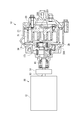
- FIG. 1st embodiment It is a figure showing a scroll compressor concerning a 1st embodiment.
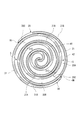
- the main part is broken and shown. It is a top view which fractures
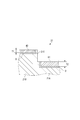
- a scroll compressor of a 2nd embodiment it is a sectional view showing a lap and an end plate in a level difference part.
- a scroll compressor of a 3rd embodiment it is a sectional view showing a lap and an end plate in a level difference part.
- the scroll compressor 10 illustrated in FIG. 1 is suitably used as a compressed air source for a brake of a railway vehicle, an air spring, and the like.
- the scroll compressor 10 includes a fixed scroll 20 fixed to a case (not shown), an orbiting scroll 30 which revolves with respect to the stationary scroll 20, and a motor 11 for applying a rotational force to the orbiting scroll 30.
- Scroll compressor 10 draws air between fixed scroll 20 and orbiting scroll 30 using motor 11 as a motive power source, and air compressed in a compression chamber S formed between stationary scroll 20 and orbiting scroll 30 Discharge.
- the scroll compressor 10 is an oil free type that does not use oil for sealing, cooling and lubrication of the scroll, unlike a conventional compressor for compressing oil for sealing, cooling and lubrication of the scroll with air.
- the scroll compressor 10 is housed in a case (not shown) together with a fan for cooling the motor 11 and the bearing portion, a device for cooling and dehumidifying compressed air to be discharged, an electrical component box, and the like.
- Grease is used to lubricate the motor 11 and the bearing portion.
- the motor 11 is configured to include a stator and a rotor housed in a motor case 12.
- the motor 11 outputs a rotational force by energizing the stator and rotating the rotor.
- the rotational force is transmitted to a shaft 15 coupled by a coupling 14 to an output shaft 13 provided on the rotor.
- an eccentric pin 151 eccentric to the axis is provided.
- the fixed scroll 20 includes a fixed end plate 200 and a spiral wrap 21 provided upright on one side of the fixed end plate 200.
- the orbiting scroll 30 also includes an orbiting end plate 300 and a spiral wrap 31 provided upright on one side of the orbiting end plate 300.
- the fixed scroll 20 and the orbiting scroll 30 are formed of metal such as aluminum, aluminum alloy, iron (cast iron, steel, etc.).
- the surface of the fixed scroll 20 and the orbiting scroll 30 may be subjected to surface treatment such as quenching or tempering, nitriding, carburizing or the like if the material is an aluminum material such as an alumite treatment if it is an aluminum material.
- the orbiting scroll 30 is coupled to the above-described eccentric pin 151 by a boss 34 provided on the back surface of the orbiting end plate 300.
- the orbiting scroll 30 revolves around the axis of the shaft 15 while the rotation of the orbiting scroll 30 is prevented by the Oldham ring (not shown).
- the wrap 21 of the fixed scroll 20 and the wrap 31 of the orbiting scroll 30 are offset from each other by a predetermined amount, and are engaged 180 degrees out of phase.
- a compression chamber S is formed in point symmetry with respect to the central portion (innermost peripheral portion) of the spirals of the wraps 21 and 31.
- a compression chamber S is formed in which the air sucked from the suction port IN is filled.
- the compression chamber S is gradually driven to the inner circumferential side while reducing its volume as the orbiting scroll 30 pivots.
- the air in the compression chamber S is discharged from the discharge port 201 (FIG. 1) formed at the center of the spiral in the fixed end plate 200.
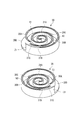
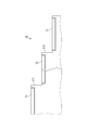
- the scroll compressor 10 is a 3D type scroll compressor, and the volume of the compression chamber S formed between both the scrolls 20 and 30 decreases in the height direction of the wraps 21 and 31 in the middle of the spiral. . Therefore, in both the fixed scroll 20 and the orbiting scroll 30, as shown in FIG. 3, the height of the wraps 21 and 31 is lower on the inner peripheral side than the outer peripheral side, and the opposite end facing the wraps 21 and 31
- the plates 300 and 200 protrude on the inner peripheral side more to the inner side than the outer peripheral side. Therefore, step portions 21C and 31C are formed on each of the wraps 21 and 31 so as to lower from the outer peripheral side to the inner peripheral side, and on each of the end plates 300 and 200, from the outer peripheral side to the inner peripheral side.
- Stepped wall 20C, 30C which becomes high is formed.
- the step walls 20C and 30C are formed in an arc shape in plan view of the end plates 200 and 300.
- the wrap 21 of the fixed scroll 20 is divided into an inner circumferential wrap 21A located on the inner circumferential side than the stepped portion 21C and an outer circumferential wrap 21B located on the outer circumferential side than the stepped portion 21C.
- the bottom portion of the swing end plate 300 facing the wrap 21 is divided into an inner circumferential bottom portion 30A and an outer circumferential bottom portion 30B with the stepped wall 30C as a boundary.
- the wrap 31 of the orbiting scroll 30 is divided into an inner circumferential wrap 31A positioned on the inner circumferential side than the stepped portion 31C and an outer circumferential wrap 31B positioned on the outer circumferential side relative to the stepped portion 31C.
- the bottom of the fixed end plate 200 facing the wrap 31 is divided into an inner circumferential bottom 20A and an outer circumferential bottom 20B at the step wall 20C.
- an inner circumferential tip seal 41 is provided at the tip of the inner circumferential wrap 21 ⁇ / b> A of the fixed scroll 20.
- the inner circumferential tip seal 41 is interposed between the inner circumferential wrap 21 ⁇ / b> A and the inner circumferential bottom portion 30 ⁇ / b> A of the pivoting end plate 300.
- the inner circumferential tip seal 41 is provided substantially over the entire area from the beginning of the inner circumferential wrap 21A located near the stepped portion 21C to the end of the inner circumferential wrap 21A located at the center of the spiral.
- an outer peripheral tip seal 42 is provided at the tip of the outer peripheral wrap 21B of the fixed scroll 20.
- the outer circumferential tip seal 42 is interposed between the outer circumferential wrap 21 B and the outer circumferential bottom portion 30 B of the turning end plate 300.
- the outer circumferential tip seal 42 is provided substantially over the entire area from the start end of the outer circumferential wrap 21B located at the outermost circumference of the spiral to the end of the outer circumferential wrap 21B located near the stepped portion 21C.
- the inner circumferential tip seal 41 and the outer circumferential tip seal 42 are formed to have the same thickness.
- an inner circumferential tip seal 51 is provided at the tip of the inner circumferential wrap 31A.
- the inner circumferential tip seal 51 is interposed between the inner circumferential wrap 31 ⁇ / b> A and the inner circumferential bottom portion 20 ⁇ / b> A of the fixed end plate 200.
- the inner circumferential tip seal 51 is formed in the same manner as the inner circumferential tip seal 41.
- an outer circumferential tip seal 52 is provided at the tip of the outer circumferential wrap 31B.
- the outer circumferential tip seal 52 is interposed between the outer circumferential wrap 31 B and the outer circumferential bottom portion 20 B of the fixed end plate 200.
- the outer circumferential tip seal 52 is formed in the same manner as the outer circumferential tip seal 42.
- tip seals 41, 42, 51, 52 are accommodated in a seal groove D formed in a lap in which they are provided, as shown in FIG.
- compressed air is introduced to the back side of the tip seal along the seal groove D from the gap G between the inner wall of the seal groove D located on the inner circumferential side and the tip seal.
- the pressure on the surface side of the tip seal is lower than that on the back side, so the tip seal floats up from the seal groove D and is pressed against the end plate. Then, since the gap between the tip seal and the end plate is sealed, the compression chamber S is kept airtight.
- the present embodiment is characterized in that the materials of the inner circumferential tip seals 41 and 51 and the outer circumferential tip seals 42 and 52 are different.
- the material of the inner tip seal 41, 51 and the material of the outer tip seals 42, 52 are determined based on the temperature and pressure rising with the compression of the air.
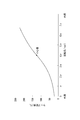
- FIG. 5 shows how the temperatures of the wraps 21 and 31 rise from the outermost circumference (0 rad) of the spiral toward the center (innermost circumference) of the spiral.
- the range from 0 rad to 2 ⁇ rad corresponds to the rotation angle from the opening of the suction port IN to the closing thereof. In the range of the rotation angle, since the inside of the compression chamber S is under the external atmosphere of the scrolls 20 and 30, the temperature hardly rises. In the example shown in FIG.
- the temperature of the wraps 21 and 31 at 2 ⁇ rad from the outermost periphery remains at about 50 ° C.
- the temperature of the wraps 21 and 31 also increases with the temperature rise of the air due to compression, and rises to 225 ° C. in the center of the spiral (about 7 ⁇ rad).
- the temperature shown in FIG. 5 is an example.
- the gradient of the temperature or temperature rise changes according to the volume and compression ratio of the compression chamber S and the rotation angle from the outermost circumference to the innermost circumference of the wraps 21 and 31. In either case, the temperature rise from the outermost circumference to 2 ⁇ Is similar, and the temperature rises gradually as it goes to the central part over 2 ⁇ .
- the inner tip seal 41, 51 which is in charge of the inner circumferential side of the wraps 21, 31 including the central portion of the spiral is required to have heat resistance that can withstand the high temperature as described above.
- the inner circumferential tip seals 41 and 51 are strongly pressed against the end plates and slide compared to the outer circumferential tip seals 42 and 52, the inner circumferential tip seals 41 and 51 The frictional force between the and the end plate is large. Therefore, in order to prevent the inner tip seal 41, 51 from being worn out prematurely due to wear, the inner tip seal 41, 51 is also required to have wear resistance.
- the inner tip seal 41, 51 which is responsible for the high temperature inner circumferential side and also exerts frictional heat with the end plate, has a large thermal expansion.
- the inner circumferential tip seals 41 and 51 when the inner circumferential tip seals 41 and 51 are strongly pressed by the end plates, the wear becomes remarkable. In order to reduce the amount of wear, it is desirable that the inner circumferential tip seals 41 and 51 have a small linear expansion coefficient.
- the outer peripheral tip seals 41 and 51 may be pressed against the end plates 300 and 200 even if they are pressed against the end plates 300 and 200. A gap may occur between the tip seals 42, 52 and the end plates 300, 200. In order to avoid this, it is preferable to balance the linear expansion coefficient of the inner peripheral tip seals 41 and 51 and the linear expansion coefficient of the outer peripheral tip seals 42 and 52.
- the material of the inner tip seal 41, 51 is selected from resins or metals which satisfy the heat resistance and the abrasion resistance under the high temperature and high pressure conditions as described above.
- the resin that can be used for the inner circumferential tip seals 41 and 51 include PI (polyimide), PEEK (polyether ether ketone), PTFE (polytetrafluoroethylene) and the like.
- PAI polyamide imide
- PPS polyphenylene sulfide
- the inner tip seal 41, 51 can be formed by injection molding or the like from the above-described resin.
- the inner tip seal 41, 51 can also be formed, for example, from a metal such as iron by press punching or the like.
- the respective materials of the inner circumferential tip seals 41 and 51 may be different.
- PI (example): 240 ° C., 1.7 to 4.5 ⁇ 10 ⁇ 5 / ° C.
- PEEK (example): 260 ° C, 3.0 to 5.7 ⁇ 10 -5 / ° C
- PTFE (example): 260 ° C., 8.3 to 15.2 ⁇ 10 ⁇ 5 / ° C.
- PAI (example): 250 ° C, 4.0 ⁇ 10 -5 / ° C
- PPS (example): 230 ° C, 1.8 to 8.7 ⁇ 10 -5 / ° C
- the heat resistance and wear resistance required for the inner circumferential tip seals 41, 51 vary depending on the temperature and pressure at the center of the spiral. In the example shown in FIG. 5, it is preferable that the heat-resistant temperature of the inner peripheral chip seals 41 and 51 is 240 ° C. or higher.
- the outer peripheral tip seals 42 and 52 handle the outer peripheral side of the wraps 21 and 31 including the outermost periphery where air is sucked, the temperature rise is small, and the back pressure is lower than the inner peripheral side, and the pressing load is also small. . Therefore, the outer circumferential tip seals 42, 52 may have lower heat resistance and wear resistance than the inner circumferential tip seals 41, 51, and may have a high linear expansion coefficient.
- resins that can be used for the outer peripheral chip seals 42 and 52 include PAI (polyamide imide), PPS (polyphenylene sulfide), PA (polyamide) and the like. Besides, PTFE (polytetrafluoroethylene) can also be adopted.
- the outer circumferential tip seals 42, 52 can also be formed of metal such as iron.
- both the inner peripheral tip seals 41 and 51 and the outer peripheral tip seals 42 and 52 may be formed of materials having the same heat resistance temperature and different specific wear amounts or linear expansion coefficients. Alternatively, both are formed of materials having similar specific wear amounts and different heat resistance temperatures or linear expansion coefficients, or formed of materials having similar linear expansion coefficients and different heat resistance temperatures or specific wear amounts.
- the outer tip seal 42, 52 has necessary heat resistance and wear resistance. As long as the above condition is satisfied, a material cheaper than the material of the inner tip seal 41, 51 is used.
- the positions of the step portions 21C and 31C separating the inner chip seal 41, 51 and the outer chip seal 42, 52 are set.
- the positions of the step portions 21C and 31C refer to portions where the outer peripheral wrap 21B rises from the inner peripheral wrap 21A.
- the first index is an angle corresponding to the center value of the temperature range in which the temperature of the wraps 21 and 31 rises.
- the second index is 2 ⁇ rad, which is the rotation angle when the orbiting scroll 30 makes one rotation.
- the temperature range of the wraps 21 and 31 is from 25 ° C. at 0 rad to 225 ° C. at about 7 ⁇ rad, and its center value is 125 ° C.
- the rotation angle corresponding to the center value 125 ° C. is 4 ⁇ rad (first index).
- 2 ⁇ rad (second index) corresponding to one rotation corresponds to a rotation angle from the opening of the suction port IN to the outermost periphery of the wraps 21 and 31 until the suction port IN is closed.
- the 2 ⁇ rad is used to reliably obtain a cost reduction effect by selecting an inexpensive material for the outer peripheral tip seals 42 and 52.
- the positions of the step portions 21C and 31C in the range of 2 ⁇ rad or more and 4 ⁇ rad or less from the outermost periphery of the wraps 21 and 31 using the first and second indicators.
- the heat-resistant temperature of the outer peripheral tip seals 42, 52 can be suppressed to a temperature equal to or less than the central value of the rising temperature range.
- the lengths of the outer peripheral chip seals 42 and 52 can be secured to 2 ⁇ rad or more. Then, cost reduction effects can be reliably obtained by selecting inexpensive materials for the outer peripheral tip seals 42 and 52.
- the positions of the step portions 21C and 31C are set to 2 ⁇ , but the step portions 21C, 21C and 31C can be provided at any position in the range of 2 ⁇ rad or more and 4 ⁇ rad or less from the outermost periphery of the wraps 21 and 31 31C can be provided.
- the steps portions 21C and 31C are 3 ⁇ rad or more from the outermost periphery to the inner peripheral side, the step portions 21C and 31C are in the compression chamber S when the suction port IN is closed and the inside of the compression chamber S is closed. Does not exist.
- the compression chamber S has a uniform space between the end plates 200 and 300, and the volume does not decrease in the height direction of the wraps 21 and 31.
- the compression ratio can be secured large.
- a slight error due to a dimensional error or an assembly error of the scrolls 20 and 30 is allowed at the positions of the step portions 21C and 31C.
- the outer circumferential tip seals 42 and 52 are formed of inexpensive materials while the inner circumferential tip seals 41 and 51 are formed of a material which is derived from the high temperature and high pressure at the central portion of the spiral. Therefore, the state in which the gap between the wraps 21 and 31 and the end plates 300 and 200 is sealed is maintained without causing the chip seal to melt, abnormal wear, seizing or the like, and the reliability of the scroll compressor 10 is improved. While being able to ensure, it can also contribute to cost reduction.
- the inner tip seal 41 has a wear resistant coating 45 on the surface.
- a material of the coating 45 for example, PTFE (polytetrafluoroethylene), PEEK (polyether ether ketone), DLC (diamond like carbon), TiN (titanium nitride), CrN (chromium nitride) or the like can be used.
- the abrasion resistance of the coating 45 is appropriately set according to the pressure at the center of the spiral.
- the film thickness of the coating 45 can be set in accordance with the specific wear amount required for the coating 45.
- the coating 45 constitutes at least a surface 45S (surface) facing the inner peripheral bottom portion 30A of the end plate 300 in the inner circumferential tip seal 41, and faces the opposite end plate 300.
- the material of the portion (coating 45) facing the end plate 300 of the inner circumferential tip seal 41 is different from the material of the portion facing the end plate 300 of the outer circumferential tip seal 42 which is not coated.
- the inner circumferential tip seal 51 can also be coated with the same coating 45 as the inner circumferential tip seal 41.
- the coating 45 of PTFE and PEEK is coated by spraying a liquid obtained by mixing resin powder in a solution onto the inner tip seal 41, 51 (base material) with an air spray gun, and heating at a temperature above the melting point of the resin. It can be formed by welding. Painting and heating are repeated until a predetermined film thickness is obtained.
- an air spray method there is also an electrostatic powder coating method in which resin powder is coated on a substrate using static electricity, a dip (dip) method, etc. Is welded to the substrate.
- the coating 45 of DLC can be formed by plasma-enhanced chemical vapor deposition (PECVD) or physical vapor deposition (PVD).
- the coating 45 of TiN and CrN can be formed by PVD.
- the material of the base material of the inner tip seal 41, 51 on which the coating 45 is formed is selected so as not to melt by the heat applied in the process of forming the coating 45.
- the base material of the inner circumferential tip seals 41, 51 can be made of the same material as the outer circumferential tip seals 42, 52.
- the inner circumferential tip seals 41 and 51 can have higher wear resistance than the outer circumferential tip seals 42 and 52. Therefore, by making the material of the base material of the inner peripheral tip seals 41, 51 the same as the material of the outer peripheral tip seals 42, 52, the necessary wear resistance can be realized while suppressing the material cost. Also, even if it is difficult to use as the material of the base material of the chip seal in terms of thickness and cost, by selecting the material of the coating 45 that is superior in wear resistance to the material that can be used as the base material. And abrasion resistance can be further improved.
- the coefficient of friction of the surface of the inner tip seal 41, 51 decreases.
- the friction coefficient of DLC is about 0.1 (drying condition).
- the abrasion resistance can be increased also at the point where the amount of abrasion decreases because the coefficient of friction is small.
- the base material of the inner circumferential tip seals 41, 51 may be formed of a material different from the material of the outer circumferential tip seals 42, 52. It is also permissible to apply a coating of a material different from the coating 45 applied to the inner peripheral tip seals 41, 51 to the outer peripheral tip seals 42, 52.
- a third embodiment of the present invention will be described with reference to FIG. Also in the third embodiment, differences from the first embodiment are mainly described, and the same reference numerals are given to the same components as the components described above.
- the thicknesses of both the inner circumferential tip seal and the outer circumferential tip seal are different.
- the materials of both the inner circumferential tip seal and the outer circumferential tip seal are the same.
- the thickness of each of the inner circumferential tip seal 61 provided on the inner circumferential wrap 21A and the outer circumferential tip seal 42 provided on the outer circumferential wrap 21B is different.
- the inner circumferential tip seal provided on the inner circumferential wrap 31 A is formed in the same manner as the inner circumferential tip seal 61, and the outer circumferential tip seal provided on the outer circumferential wrap 31 B is also formed similarly to the outer circumferential tip seal 42.
- the thickness of the outer circumferential tip seal 42 is set to T1. This thickness is the same as the thickness of the outer peripheral tip seal 42 in the first embodiment and the second embodiment.
- the thickness T 2 of the inner circumferential tip seal 61 is larger than the thickness T 1 of the outer circumferential tip seal 42.
- the inner circumferential tip seal 61 is thick, even if the inner circumferential tip seal 61 is worn out to a large extent, a thickness sufficient for sealing can be left. Thereby, the reliability of the tip seal can be secured. In addition, since the thickness T1 of the outer circumferential tip seal 42 can be maintained to a thickness sufficient for sealing, the cost can be suppressed.
- the third embodiment can also be combined with the first embodiment or the second embodiment. That is, in the third embodiment, both the inner circumferential tip seals 41 and 51 and the outer circumferential tip seals 42 and 52 may be formed of different materials, or the inner circumferential tip seals 41 and 51 may be coated with the coating 45. .
- the configuration of each of the first to third embodiments makes the inner circumferential tip seal durable. Providing the property is effective in the air-compressing scroll compressor.
- the scroll compressor 10 is oil free, the temperature rise on the inner circumferential side becomes remarkable because the effect of cooling by the oil can not be obtained.
- the lubricating action by oil can not be obtained, and the tip seal is apt to be worn because it is slid directly on the end plate without lubricating oil. Therefore, when the present invention is applied to an air-compressed and oil-free scroll compressor, the effects of the present invention are remarkable. Even in the scroll compressor that compresses the refrigerant, the high temperature and high compression ratio may be as high as that of air compression at the center of the spiral like a scroll compressor used for a large freezer or an air conditioner. Also in that case, the effect of the present invention is great. The effect of the present invention is also remarkable in such an oil-free scroll compressor which performs refrigerant compression.
- the stepped portion is provided only at one place in the circumferential direction of the wrap, but the stepped portions may be provided at a plurality of places in the circumferential direction of the wrap. For example, as shown in FIG. 8, if the step portions 211 and 212 are provided at two places in the circumferential direction of the wrap 21, the innermost chip seal provided at the position including the innermost circumference (central part of the spiral) 71, an outermost tip seal 73 provided at a position including the outermost circumference, and an intermediate tip seal 72 provided at an intermediate position.
- first step portion 211 one located on the outer peripheral side
- second step portion 212 one located on the inner peripheral side
- the thickness can be made different.
- the innermost tip seal 71 positioned on the inner peripheral side of the second stepped portion 212 with respect to the second stepped portion 212, the intermediate tip seal 72 positioned on the outer peripheral side of the second stepped portion 212, and the outermost The material or thickness can be made different from that of the outer circumferential tip seal 73. Furthermore, the material or thickness of each of the outermost tip seal 73, the middle tip seal 72, and the innermost tip seal 71 may be made different stepwise.
- the intermediate chip seal 72 positioned on the inner circumferential side of the first step portion 211 and the outermost tip seal 73 positioned on the outer circumferential side of the first step portion 211 are different in material or thickness
- the material or thickness can be made different between the innermost tip seal 71 positioned on the inner circumferential side of the two step portion 212 and the intermediate tip seal 72 positioned on the outer side of the second step portion 212.
- the temperature and pressure of the gas increase from the outermost periphery to the innermost periphery of the lap, the temperature is higher on the inner periphery side and the pressure is higher.
- the material of the inner tip seal is made more excellent in heat resistance and wear resistance than the outer tip seal located relatively on the outer circumferential side, and the thickness of the inner tip seal is thicker than the outer tip seal. Just do it.
- the scroll compressor according to the present invention is not limited to one driven by the rotational force of the motor, and may be driven by the driving force transmitted from the engine to the shaft via the belt.
Landscapes
- Engineering & Computer Science (AREA)
- Mechanical Engineering (AREA)
- General Engineering & Computer Science (AREA)
- Rotary Pumps (AREA)
- Applications Or Details Of Rotary Compressors (AREA)
Abstract
Le problème décrit par la présente invention est l'amélioration de la fiabilité d'un compresseur à volute tridimensionnelle en améliorant la longévité des joints de bout du compresseur à volute. La solution selon l'invention consiste en un compresseur à volute tridimensionnelle (10), dont une paire de volutes (20, 30) comprend : des enveloppements (21, 31) dont la hauteur diminue par l'intermédiaire de parties étagées (21C, 31C); et des plaques d'extrémité (200, 300) sur lesquelles des parois étagées (20C, 30C) sont formées de façon à s'élever conformément aux parties étagées (31C, 21C) des enveloppements homologues (31, 21). Un joint de bout périphérique interne (41 ou 51), qui est ménagé sur le côté interne de la partie étagée (21C ou 31C) et intercalé par rapport à la plaque terminale homologue (300 ou 200), et un joint de bout périphérique externe (42 ou 52), qui est ménagé sur le côté externe de la partie étagée (21C ou 31C) et intercalé par rapport à la plaque terminale homologue (300 ou 200), sont constitués de matériaux de propriétés différentes au moins au niveau de sections faisant face aux plaques d'extrémité homologues respectives (300, 200).
Priority Applications (1)
| Application Number | Priority Date | Filing Date | Title |
|---|---|---|---|
| EP14830230.0A EP2998585B1 (fr) | 2013-07-25 | 2014-06-24 | Compresseur à volute |
Applications Claiming Priority (2)
| Application Number | Priority Date | Filing Date | Title |
|---|---|---|---|
| JP2013154204A JP6214954B2 (ja) | 2013-07-25 | 2013-07-25 | スクロール圧縮機 |
| JP2013-154204 | 2013-07-25 |
Publications (1)
| Publication Number | Publication Date |
|---|---|
| WO2015011875A1 true WO2015011875A1 (fr) | 2015-01-29 |
Family
ID=52392943
Family Applications (1)
| Application Number | Title | Priority Date | Filing Date |
|---|---|---|---|
| PCT/JP2014/003372 Ceased WO2015011875A1 (fr) | 2013-07-25 | 2014-06-24 | Compresseur à volute |
Country Status (3)
| Country | Link |
|---|---|
| EP (1) | EP2998585B1 (fr) |
| JP (1) | JP6214954B2 (fr) |
| WO (1) | WO2015011875A1 (fr) |
Cited By (3)
| Publication number | Priority date | Publication date | Assignee | Title |
|---|---|---|---|---|
| JPWO2017033546A1 (ja) * | 2015-08-25 | 2018-06-14 | 村田機械株式会社 | パージ装置、パージストッカ、及びパージ方法 |
| JP2018517097A (ja) * | 2015-04-23 | 2018-06-28 | エマソン クライメット テクノロジーズ(スーチョウ)カンパニー、リミテッド | スクロール圧縮機並びにスクロール圧縮機のための駆動軸及びアンロード・ブッシュ |
| WO2018124008A1 (fr) * | 2016-12-28 | 2018-07-05 | ナブテスコ株式会社 | Machine à fluide à spirales et véhicule |
Families Citing this family (4)
| Publication number | Priority date | Publication date | Assignee | Title |
|---|---|---|---|---|
| JP6532713B2 (ja) * | 2015-03-12 | 2019-06-19 | 三菱重工サーマルシステムズ株式会社 | スクロール圧縮機 |
| JP2019073988A (ja) * | 2017-10-12 | 2019-05-16 | アネスト岩田株式会社 | スクロール流体機械ユニット |
| DE102020134469A1 (de) * | 2020-12-21 | 2022-06-23 | OET GmbH | Scrollverdichter zur Erzeugung von ölfreier Druckluft |
| EP4032764A1 (fr) * | 2021-01-25 | 2022-07-27 | ZF CV Systems Global GmbH | Alimentation centrale en air |
Citations (9)
| Publication number | Priority date | Publication date | Assignee | Title |
|---|---|---|---|---|
| JPH02124201U (fr) | 1989-03-27 | 1990-10-12 | ||
| JPH06323101A (ja) * | 1993-05-12 | 1994-11-22 | Daikin Ind Ltd | スクロール流体機械 |
| JPH07158568A (ja) * | 1993-12-09 | 1995-06-20 | Hitachi Ltd | スクロール流体機械 |
| JP2003106269A (ja) * | 2001-09-28 | 2003-04-09 | Anest Iwata Corp | スクロール流体機械 |
| JP2009074461A (ja) * | 2007-09-21 | 2009-04-09 | Mitsubishi Heavy Ind Ltd | スクロール圧縮機 |
| JP2010275895A (ja) * | 2009-05-27 | 2010-12-09 | Mitsubishi Heavy Ind Ltd | スクロール圧縮機 |
| JP2011144801A (ja) | 2009-12-15 | 2011-07-28 | Mitsubishi Heavy Ind Ltd | スクロール圧縮機 |
| JP2013501887A (ja) * | 2009-08-14 | 2013-01-17 | エドワーズ リミテッド | スクロール型ポンプ |
| JP2013160147A (ja) * | 2012-02-06 | 2013-08-19 | Mitsubishi Heavy Ind Ltd | スクロール型圧縮機 |
Family Cites Families (1)
| Publication number | Priority date | Publication date | Assignee | Title |
|---|---|---|---|---|
| JP4395325B2 (ja) * | 2003-05-21 | 2010-01-06 | 三菱重工業株式会社 | 段付き構造スクロール流体機械 |
-
2013
- 2013-07-25 JP JP2013154204A patent/JP6214954B2/ja active Active
-
2014
- 2014-06-24 EP EP14830230.0A patent/EP2998585B1/fr active Active
- 2014-06-24 WO PCT/JP2014/003372 patent/WO2015011875A1/fr not_active Ceased
Patent Citations (9)
| Publication number | Priority date | Publication date | Assignee | Title |
|---|---|---|---|---|
| JPH02124201U (fr) | 1989-03-27 | 1990-10-12 | ||
| JPH06323101A (ja) * | 1993-05-12 | 1994-11-22 | Daikin Ind Ltd | スクロール流体機械 |
| JPH07158568A (ja) * | 1993-12-09 | 1995-06-20 | Hitachi Ltd | スクロール流体機械 |
| JP2003106269A (ja) * | 2001-09-28 | 2003-04-09 | Anest Iwata Corp | スクロール流体機械 |
| JP2009074461A (ja) * | 2007-09-21 | 2009-04-09 | Mitsubishi Heavy Ind Ltd | スクロール圧縮機 |
| JP2010275895A (ja) * | 2009-05-27 | 2010-12-09 | Mitsubishi Heavy Ind Ltd | スクロール圧縮機 |
| JP2013501887A (ja) * | 2009-08-14 | 2013-01-17 | エドワーズ リミテッド | スクロール型ポンプ |
| JP2011144801A (ja) | 2009-12-15 | 2011-07-28 | Mitsubishi Heavy Ind Ltd | スクロール圧縮機 |
| JP2013160147A (ja) * | 2012-02-06 | 2013-08-19 | Mitsubishi Heavy Ind Ltd | スクロール型圧縮機 |
Non-Patent Citations (1)
| Title |
|---|
| See also references of EP2998585A4 * |
Cited By (6)
| Publication number | Priority date | Publication date | Assignee | Title |
|---|---|---|---|---|
| JP2018517097A (ja) * | 2015-04-23 | 2018-06-28 | エマソン クライメット テクノロジーズ(スーチョウ)カンパニー、リミテッド | スクロール圧縮機並びにスクロール圧縮機のための駆動軸及びアンロード・ブッシュ |
| JPWO2017033546A1 (ja) * | 2015-08-25 | 2018-06-14 | 村田機械株式会社 | パージ装置、パージストッカ、及びパージ方法 |
| WO2018124008A1 (fr) * | 2016-12-28 | 2018-07-05 | ナブテスコ株式会社 | Machine à fluide à spirales et véhicule |
| CN110073106A (zh) * | 2016-12-28 | 2019-07-30 | 纳博特斯克有限公司 | 涡旋式流体机械和车辆 |
| JPWO2018124008A1 (ja) * | 2016-12-28 | 2019-10-31 | ナブテスコ株式会社 | スクロール式流体機械および車両 |
| CN110073106B (zh) * | 2016-12-28 | 2022-01-28 | 纳博特斯克有限公司 | 涡旋式流体机械和车辆 |
Also Published As
| Publication number | Publication date |
|---|---|
| EP2998585A1 (fr) | 2016-03-23 |
| EP2998585B1 (fr) | 2017-04-26 |
| JP6214954B2 (ja) | 2017-10-18 |
| JP2015025387A (ja) | 2015-02-05 |
| EP2998585A4 (fr) | 2016-07-20 |
Similar Documents
| Publication | Publication Date | Title |
|---|---|---|
| WO2015011875A1 (fr) | Compresseur à volute | |
| CN104662199B (zh) | 用于压缩机磨损表面的抗磨损涂层 | |
| CN103069166B (zh) | 制冷剂压缩机 | |
| AU2005205262B2 (en) | Fluid Machinery | |
| CN104074753A (zh) | 制冷剂压缩机 | |
| US8186982B2 (en) | Adjustable rotary pump with reduced wear | |
| JP4514493B2 (ja) | スクロール型流体機械 | |
| KR20170029313A (ko) | 스크롤 압축기 | |
| CN209654237U (zh) | 用于涡旋压缩机的聚合物复合材料插入部件 | |
| US10968912B2 (en) | Scroll compressor | |
| JP2013015092A (ja) | 圧縮機 | |
| CN101133126A (zh) | 滑动部件用组合物、滑动部件以及流体机械 | |
| WO2015025416A1 (fr) | Machine rotative, et appareil à cycle de réfrigération | |
| JPH11107953A (ja) | 流体圧縮機 | |
| JP2009287483A (ja) | 冷媒圧縮機 | |
| JP2007224767A (ja) | 回転式流体機械 | |
| JP2005325842A (ja) | 流体機械 | |
| JP2022542034A (ja) | スクロールポンプ | |
| JP7824736B2 (ja) | スクロールコンプレッサの環状シール部材 | |
| JP2003035284A (ja) | スクロール型ポンプの部材の表面被覆方法 | |
| WO2022054364A1 (fr) | Éléments coulissants, et compresseur et appareil de réfrigération utilisant lesdits éléments coulissants | |
| JP2008144678A (ja) | スクロール圧縮機 | |
| JP2021014811A (ja) | スクロール型流体機械 | |
| JP2004076685A (ja) | スクロール形流体機械 |
Legal Events
| Date | Code | Title | Description |
|---|---|---|---|
| 121 | Ep: the epo has been informed by wipo that ep was designated in this application |
Ref document number: 14830230 Country of ref document: EP Kind code of ref document: A1 |
|
| DPE1 | Request for preliminary examination filed after expiration of 19th month from priority date (pct application filed from 20040101) | ||
| REEP | Request for entry into the european phase |
Ref document number: 2014830230 Country of ref document: EP |
|
| WWE | Wipo information: entry into national phase |
Ref document number: 2014830230 Country of ref document: EP |
|
| NENP | Non-entry into the national phase |
Ref country code: DE |