WO2015011892A1 - Ventilateur électrique pour un dispositif de réfrigération et dispositif de réfrigération pourvu d'un ventilateur électrique - Google Patents
Ventilateur électrique pour un dispositif de réfrigération et dispositif de réfrigération pourvu d'un ventilateur électrique Download PDFInfo
- Publication number
- WO2015011892A1 WO2015011892A1 PCT/JP2014/003690 JP2014003690W WO2015011892A1 WO 2015011892 A1 WO2015011892 A1 WO 2015011892A1 JP 2014003690 W JP2014003690 W JP 2014003690W WO 2015011892 A1 WO2015011892 A1 WO 2015011892A1
- Authority
- WO
- WIPO (PCT)
- Prior art keywords
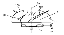
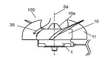
- electric blower
- motor element
- refrigeration equipment
- electric
- stator
- Prior art date
- Legal status (The legal status is an assumption and is not a legal conclusion. Google has not performed a legal analysis and makes no representation as to the accuracy of the status listed.)
- Ceased
Links
Images







Classifications
-
- F—MECHANICAL ENGINEERING; LIGHTING; HEATING; WEAPONS; BLASTING
- F04—POSITIVE - DISPLACEMENT MACHINES FOR LIQUIDS; PUMPS FOR LIQUIDS OR ELASTIC FLUIDS
- F04D—NON-POSITIVE-DISPLACEMENT PUMPS
- F04D25/00—Pumping installations or systems
- F04D25/02—Units comprising pumps and their driving means
- F04D25/06—Units comprising pumps and their driving means the pump being electrically driven
- F04D25/0606—Units comprising pumps and their driving means the pump being electrically driven the electric motor being specially adapted for integration in the pump
-
- F—MECHANICAL ENGINEERING; LIGHTING; HEATING; WEAPONS; BLASTING
- F04—POSITIVE - DISPLACEMENT MACHINES FOR LIQUIDS; PUMPS FOR LIQUIDS OR ELASTIC FLUIDS
- F04D—NON-POSITIVE-DISPLACEMENT PUMPS
- F04D19/00—Axial-flow pumps
- F04D19/002—Axial flow fans
-
- F—MECHANICAL ENGINEERING; LIGHTING; HEATING; WEAPONS; BLASTING
- F04—POSITIVE - DISPLACEMENT MACHINES FOR LIQUIDS; PUMPS FOR LIQUIDS OR ELASTIC FLUIDS
- F04D—NON-POSITIVE-DISPLACEMENT PUMPS
- F04D25/00—Pumping installations or systems
- F04D25/02—Units comprising pumps and their driving means
- F04D25/08—Units comprising pumps and their driving means the working fluid being air, e.g. for ventilation
Definitions
- the present invention relates to an electric blower that forcibly circulates cold air existing inside a refrigeration room or a freezer compartment of a refrigeration apparatus in a refrigeration apparatus such as a refrigerator or a freezer, and a refrigeration apparatus equipped with the electric blower.
- Refrigeration equipment such as refrigerators and freezers are always operated. In each home, refrigeration equipment is equipment that consumes a large amount of power. Therefore, conventionally, refrigeration equipment is desired to save power and reduce noise.
- the compressor consumes the most power.
- the electric power consumed by the compressor can be reduced by a countermeasure described later. That is, the refrigeration equipment has a freezing room, a refrigeration room, etc. inside the freezing equipment.
- the refrigeration equipment has an electric blower that circulates cold air in each room.
- the electric blower includes an electric motor element and a fan. The fan is driven by the motor element.
- the refrigeration equipment can keep the temperature in each room low by effectively circulating the cold air in each room using an electric blower. In the refrigeration equipment, if the temperature in each room is kept low, the load on the compressor is reduced. For these reasons, electric blowers used in refrigeration equipment are strongly required to have high efficiency, high air volume, and low noise.
- Patent Document 1 discloses an electric blower including an electric motor element larger than the hub cap of the fan.
- Patent Literature 2 discloses an electric blower including an outer rotor type electric motor element.
- An electric blower for refrigeration equipment targeted by the present invention includes an axial fan and an electric motor element.
- ⁇ Axial fans are formed by integrally molding a plurality of blades and a cup-shaped hub cap.
- the cup-shaped hub cap has a protrusion at the center.
- the electric motor element includes a stator, a rotor, a pair of bearings, and a resin sheathing body.
- the stator has a stator core and a winding.
- the stator core includes a plurality of teeth, a slot, and a yoke.
- the plurality of teeth includes a wide portion at the tip of each tooth.
- the plurality of teeth are arranged substantially radially.
- a slot is a gap formed between adjacent teeth.
- the yoke connects a plurality of teeth at the outer periphery.
- the winding covers the core wire with an insulating coating. The winding is wound around the teeth via an insulator.
- the rotor has a shaft and a permanent magnet.
- the shaft extends along the axis and has one end as an output shaft.
- the permanent magnet is opposed to the wide portion through a gap inside the stator, and is located in the circumferential direction along the axis.
- ⁇ A pair of bearings support the shaft rotatably.
- the resin armor covers at least a part of the stator.
- the resin exterior body has a plurality of mounting legs including mounting holes.
- the output shaft is fixed by the protrusion so that the axial fan and the motor element are positioned inside the hub cap.
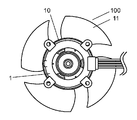
- FIG. 1A is a front view of the electric blower according to Embodiment 1 of the present invention.
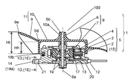
- 1B is a cross-sectional view taken along the line 1B-O-1B shown in FIG. 1A.
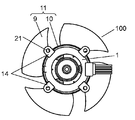
- FIG. 1C is a rear view of the electric blower according to Embodiment 1 of the present invention.
- 1D is a 1D-1D cross-sectional view shown in FIG. 1B.
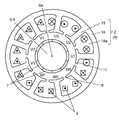
- 1E is a cross-sectional view taken along the line 1E-1E shown in FIG. 1B.
- FIG. 2A is a conceptual diagram showing a winding state of an electric motor element used in the electric blower in Embodiment 1 of the present invention.
- FIG. 1A is a conceptual diagram showing a winding state of an electric motor element used in the electric blower in Embodiment 1 of the present invention.
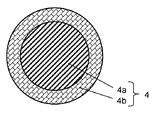
- FIG. 2B is a cross-sectional view of a winding of an electric motor element used in the electric blower in Embodiment 1 of the present invention.
- FIG. 2C is a cross-sectional view of another winding of the motor element used in the electric blower in Embodiment 1 of the present invention.
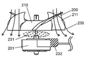
- FIG. 3 is a block diagram showing a circuit configuration of an electric motor element used in the electric blower according to Embodiment 1 of the present invention.
- FIG. 4A is a side view of an electric blower of a comparative example.
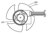
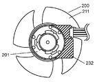
- FIG. 4B is a rear view of the electric blower of the comparative example.
- FIG. 5A is a conceptual diagram illustrating airflow generated by the electric blower of the comparative example.
- FIG. 5B is a conceptual diagram illustrating the state of FIG.
- FIG. 5A is a conceptual diagram showing an air flow generated by the electric blower according to Embodiment 1 of the present invention.
- FIG. 5D is a conceptual diagram illustrating the state of FIG. 5C.
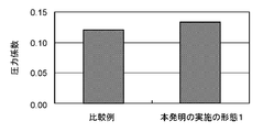
- FIG. 6 is a graph showing the results of comparing the pressure coefficients using the electric blower according to the embodiment of the present invention and the electric blower of the comparative example.
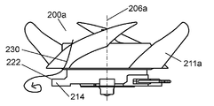
- FIG. 7A is a conceptual diagram showing an air flow generated by an electric blower of another comparative example.
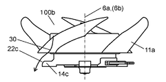
- FIG. 7B is a conceptual diagram showing an air flow generated by another electric blower according to Embodiment 1 of the present invention.
- FIG. 7C is a conceptual diagram showing an air flow generated by still another electric blower according to Embodiment 1 of the present invention.
- FIG. 8A is a conceptual diagram showing an airflow generated by an axial fan used by the electric blower in Embodiment 1 of the present invention.
- FIG. 8B is a conceptual diagram showing an air flow generated by another axial fan used by the electric blower in Embodiment 1 of the present invention.
- FIG. 9 is a conceptual diagram showing a refrigeration apparatus according to Embodiment 2 of the present invention.
- the electric blower for refrigeration equipment in the embodiment of the present invention can increase the air volume and reduce vibration and noise by the configuration described later. Moreover, since the electric blower in embodiment of this invention has the short shaft length, it can implement
- the conventional electric blower had the following points to be improved. That is, in the electric blower disclosed in Patent Document 1, the electric motor element is larger than the hub cap of the fan. Therefore, the electric blower disclosed in Patent Document 1 cannot arrange the electric motor element inside the hub cap of the fan. Therefore, in the electric blower disclosed in Patent Document 1, the fan and the electric motor element are assembled while maintaining an appropriate distance in the axial direction of the shaft of the electric motor element.
- the electric motor element hinders the air flow field formed by the fan. That is, the electric motor element has been a factor of reducing the blowing efficiency.
- the length of the shaft of the electric motor element is long. Therefore, the resonant frequency which the electric blower disclosed by patent document 1 has becomes low. When the resonance frequency of the electric blower is low, noise may occur in the range where the electric blower is driven at the rated value.
- the outer rotor type electric motor element is arranged inside the hub cap of the fan.
- the rotor has a cantilever structure.
- the outer rotor type motor elements tend to have a larger outer diameter of the rotor than the inner rotor type motor elements.
- FIG. 1A is a front view of the electric blower according to Embodiment 1 of the present invention.
- 1B is a cross-sectional view taken along the line 1B-O-1B shown in FIG. 1A.
- FIG. 1C is a rear view of the electric blower according to Embodiment 1 of the present invention.
- 1D is a 1D-1D cross-sectional view shown in FIG. 1B.
- 1E is a cross-sectional view taken along the line 1E-1E shown in FIG. 1B.
- FIG. 2A is a conceptual diagram showing a winding state of an electric motor element used in the electric blower in Embodiment 1 of the present invention.
- FIG. 2B is a cross-sectional view of a winding of an electric motor element used in the electric blower in Embodiment 1 of the present invention.
- FIG. 2C is a cross-sectional view of another winding of the motor element used in the electric blower in Embodiment 1 of the present invention.
- FIG. 3 is a block diagram showing a circuit configuration of an electric motor element used in the electric blower in Embodiment 1 of the present invention.
- FIG. 7A is a conceptual diagram showing an air flow generated by an electric blower of another comparative example.
- FIG. 7B is a conceptual diagram showing an air flow generated by another electric blower according to Embodiment 1 of the present invention.
- FIG. 7C is a conceptual diagram showing an air flow generated by still another electric blower according to Embodiment 1 of the present invention.
- the electric blower 100 for the refrigeration equipment in Embodiment 1 of the present invention includes an axial flow fan 11 and an electric motor element 1.
- the axial fan 11 is formed by integrally molding a plurality of blades 9 and a cup-shaped hub cap 10.
- the cup-shaped hub cap 10 has a protrusion 10a at the center.
- the electric motor element 1 includes a stator 5, a rotor 8, a pair of bearings realized by, for example, a slide bearing 19, and a resin outer casing realized by, for example, a stator outer casing 20.
- the stator 5 has a stator core 2 and a winding 4.
- the stator core 2 includes a plurality of teeth 15, a slot 18 a, and a yoke 16.
- the plurality of teeth 15 include a wide portion 17 at the tip of each tooth 15.
- the several teeth 15 are arrange
- the slot 18a is a gap formed between adjacent teeth 15.
- the yoke 16 connects the plurality of teeth 15 at the outer periphery.
- the winding 4 covers the core wire 4a with an insulating coating 4b. As shown in FIG. 1B, the winding 4 is wound around the tooth 15 via the insulator 3.
- the rotor 8 has a shaft 6 and a permanent magnet 7.
- the shaft 6 extends along the axis 6a and has one end as an output shaft 6b.
- the permanent magnet 7 is opposed to the wide portion 17 through a gap inside the stator 5 and is positioned in the circumferential direction along the axis 6 a.
- the sliding bearing 19 which is a pair of bearings rotatably supports the shaft 6.
- the stator outer body 20 which is a resin outer body covers at least a part of the stator 5.
- the stator exterior body 20 which is a resin exterior body has a plurality of attachment feet 14 including attachment holes 21.
- the electric blower 100 for the refrigeration equipment is provided with the protrusion 10 a of the axial flow fan 11 and the output of the electric motor element 1 so that the electric motor element 1 is positioned inside the hub cap 10. It is fixed with the shaft 6b.
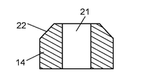
- each mounting foot 14 has an output shaft in a cross-sectional shape in the direction along the axis 6a.
- the shoulder 22 located on the 6b side is chamfered.
- each mounting foot 14a is a shoulder located on the output shaft 6b side in the cross-sectional shape in the direction along the axis 6a. 22a is a curve shape.
- each mounting foot 14b is a tip portion located on the opposite side of the shaft center 6a in the cross section including the shaft center 6a. Further, the shoulder 22b located on the output shaft 6b side is chamfered.
- each attachment foot 14c is a tip portion located on the opposite side of the shaft center 6a in the cross section including the shaft center 6a.
- the shoulder part 22c located in the output-shaft 6b side is a curve shape.
- the protrusion 10a has a mountain shape protruding to the opposite side to the direction in which the electric motor element 1 is located.
- the outer edge portion 9a of the blade 9 is on a plane orthogonal to the axis 6a and in the rotational direction in which the axial fan 11 rotates. And the position of the front edge part 9c which exists ahead of a rotation direction is set to Pt.
- Ph is the position of the front edge portion 9c that is the portion 9b where the blade and the hub cap are in contact and is present in the forward direction of the rotation direction. At this time, each blade 9 is positioned forward in the rotational direction at position Pt relative to position Ph.
- the stator used in the electric blower in the first embodiment includes nine teeth 15 and windings 4 as a plurality of teeth 15.
- the winding 4 is wound around the nine teeth 15 so as to form a three-phase concentrated winding.
- the rotor 8 has a permanent magnet 7 constituting 10 poles.
- the winding 4 used in the electric blower in the first embodiment has a core wire 4a of at least copper, aluminum, a copper alloy containing copper, and an aluminum alloy containing aluminum. Contains one.
- the winding 40 used in the electric blower in Embodiment 1 has a coating layer 4c between the core wire 4a and the insulating coating 4b.
- the coating layer 4c contains any one of copper or a copper alloy containing copper.
- At least one of the pair of bearings used in the electric blower 100 according to the first embodiment is a slide bearing 19.
- the permanent magnet 7 used in the electric blower in Embodiment 1 is a plastic magnet material molded into a cylindrical shape.
- the electric motor element 1 further includes a power connection body 12 and a circuit wiring board 13.
- the power connector 12 transmits power supplied from the outside of the motor element 1 to the winding 4.
- a control circuit for controlling the power supplied to the winding 4 is mounted on the circuit wiring board 13. In the direction along the axis 6a, the circuit wiring board 13 is located on the opposite side to the output shaft 6b with respect to the stator 5.
- the electric motor element 1 further includes a wiring through which a current based on electric power flows between the power connection body 12 and the winding 4. 23.
- the control circuit 24 includes a drive element 25 and a control element 26.
- the drive element 25 adjusts the current supplied to the winding 4.
- the control element 26 operates the drive element 25.
- the control element 26 includes a control unit 26a and a magnetic pole detection element 26b.
- the stator outer body 20 that is a resin outer body integrally covers the power connection body 12 and the circuit wiring board 13. .
- the electric motor element 1 used for the electric blower in the first embodiment has the following configuration. That is, in the motor element 1, the number of poles of the rotor 8 formed based on the permanent magnet 7 is p. The number of slots formed by the stator 5 is s. In the axial fan 11, the number of blades 9 is z. Furthermore, let n be an arbitrary natural number. At this time, the electric motor element 1 has a relationship of p ⁇ nz or s ⁇ nz.
- the electric motor element 1 the number of poles of the rotor 8 formed based on the permanent magnet 7 is p.
- the number of slots formed by the stator 5 is s.
- the number of blades 9 is z.
- n be an arbitrary natural number. At this time, the electric motor element 1 has a relationship of z ⁇ np or z ⁇ ns.
- FIG. 1A to 1C show electric blower 100 for refrigeration equipment according to Embodiment 1 of the present invention.
- the electric motor element 1 includes a stator core 2, a stator 5, and a rotor 8.
- the stator core 2 is formed by laminating magnetic materials.
- the stator 5 has a winding 4 wound around a tooth 15 via an insulator 3.
- the rotor 8 is opposed to the inner side of the stator 5 in the circumferential direction along the axis 6a through a slight gap.
- the rotor 8 is rotatably held by the shaft 6.
- the rotor 8 has a permanent magnet 7 magnetized with a plurality of poles.
- the axial fan 11 has a plurality of blades 9 and a cup-shaped hub cap 10.
- the hub cap 10 has an opening on one side.
- the hub cap 10 is formed of a hollow body including a protrusion 10a at a position serving as a rotation center on the opposite side of the opening.
- the electric motor element 1 is covered with a hub cap 10 of an axial fan 11.
- the electric motor element 1 and the axial fan 11 are fixed to the shaft 6 of the electric motor element 1 and the central portion of the hub cap 10 of the axial fan 11.
- the axial fan 11 is rotationally driven by the electric motor element 1.
- a power connection body 12 and a circuit wiring board 13 are arranged on the opposite side where the axial fan 11 is located.
- the circuit wiring board 13 is attached with components constituting a control unit that controls a current supplied to the winding 4 wound around the stator 5.
- the electric motor element 1 has a plurality of mounting feet 14 for mounting the electric blower 100 to the refrigeration equipment.
- FIG. 4A is a side view of an electric blower of a comparative example.
- FIG. 4B is a rear view of the electric blower of the comparative example.
- FIG. 5A is a conceptual diagram showing an airflow generated by the electric blower of the comparative example.
- FIG. 5B is a conceptual diagram illustrating the state of FIG. 5A.
- FIG. 5C is a conceptual diagram showing an air flow generated by the electric blower according to Embodiment 1 of the present invention.
- FIG. 5D is a conceptual diagram illustrating the state of FIG. 5C.
- FIG. 4A and FIG. 4B show an electric blower 200 of a comparative example compared with Embodiment 1 of the present invention.
- the electric motor element 201 is larger than the hub cap 210 included in the axial fan 211. More specifically, the outer diameter dimension of the motor element 201 is larger than the inner diameter dimension of the hub cap 210.
- the axial fan 211 and the electric motor element 201 are arranged at a certain distance in the axial center 206a direction of the shaft 206.
- the electric blower 200 having the above-described configuration is driven. At this time, as shown in FIG. 5A, the electric blower 200 obtains an airflow 230 by the axial fan 211. In addition, in the electric blower 200, a low pressure region 231 in which the pressure is reduced is generated between the axial fan 211 and the electric motor element 201.
- FIGS. 5A and 5B a part of the airflow 230 collides with the shielding part 232 included in the electric motor element 201.
- the shielding part 232 is indicated by oblique lines.
- the electric motor element 1 including the circuit wiring board is accommodated inside the hub cap 10 included in the axial fan 11.
- the electric blower 100 the airflow 30 obtained by the axial fan 11 is not disturbed by the electric motor element 1.
- the electric blower 100 can reduce the loss of airflow that has occurred in the comparative example. Therefore, in the electric blower 100, the efficiency is improved and the air volume is increased.
- FIG. 6 is a graph showing a result of comparing pressure coefficients using the electric blower according to Embodiment 1 of the present invention and the electric blower of the comparative example. The pressure coefficient was calculated by fluid analysis.
- the pressure coefficient of the electric blower 200 of the comparative example was 0.120.
- the pressure coefficient by electric blower 100 in Embodiment 1 of the present invention was 0.133. That is, the pressure coefficient difference was 0.013. From these results, in the electric blower 100 according to Embodiment 1 of the present invention, the result that the output of the axial fan 11 was increased by about 10% was obtained.
- FIG. 7A shows an electric blower 200a of a comparative example compared with Embodiment 1 of the present invention.
- the mounting foot 214 included in the electric blower 200a is a front end portion located on the opposite side of the shaft center 206a and a shoulder portion located on the output shaft side in the cross section including the shaft center 206a. 222 is not devised for the airflow 230.
- the airflow 230 generated by the axial fan 211a and flowing from the upper side to the lower side in the drawing collides with the mounting foot 214.
- the flow direction of the airflow 230 is rapidly changed. Specifically, the airflow 230 is bent in a direction having a large angle from the axial direction.
- each attachment foot 14b is a tip portion located on the opposite side of the shaft center 6a in the cross section including the shaft center 6a.
- the shoulder 22b located on the output shaft side is chamfered.
- each mounting foot 14c is a tip portion located on the opposite side of the shaft center 6a in the cross section including the shaft center 6a.
- the shoulder part 22c located in the output-shaft side is a curve shape.
- the airflow 30 generated from the axial fan 11a flowing from the upper side to the lower side in the drawing does not abruptly change the flow direction after colliding with the mounting feet 14b and 14c. That is, the change in the flowing direction of the airflow 30 is alleviated.
- a separation vortex of the airflow 230 was generated at the shoulder 222 located at the tip of the mounting foot 214 of the comparative example.
- the change in the direction in which the airflow 30 flows is mitigated, so that the generation of separation vortices is suppressed.
- the electric blower according to the first embodiment can further improve efficiency and reduce noise.
- the mounting foot 14 is chamfered on the side where the axial fan is located.
- the mounting foot 14a has a curved shape on the side where the axial fan is located.
- the attachment foot 14a has an arc shape.
- the direction in which the axial fan is located refers to the upstream side of the airflow generated by the axial fan.
- the other electric blower according to the first embodiment can further improve efficiency and reduce noise.
- FIG. 8A is a conceptual diagram showing an airflow generated by an axial fan used by the electric blower in Embodiment 1 of the present invention.
- FIG. 8B is a conceptual diagram showing an air flow generated by another axial fan used by the electric blower in Embodiment 1 of the present invention.
- the electric blower according to the first embodiment of the present invention exhibits a remarkable effect by adopting a configuration that will be described later.
- the axial fan 11 generates the air flow 30 from the side where the axial fan 11 is attached toward the side where the electric motor element 1 is attached.
- the hub cap 10 constituting the axial fan 11 has a chevron-shaped protrusion 10 a that protrudes on the opposite side to the direction in which the electric motor element 1 is located.
- the protrusion 10a is used for fitting the shaft of the electric motor element 1 and the hub cap 10 together.
- the air flow 30 can collide with the hub cap 10 to reduce the air flow that is lost. Therefore, the fall of the ventilation performance of the electric blower 100 can be suppressed.
- the cross-sectional area of the chevron shape of the protrusion 10a should be larger on the side where the motor element 1 is located than on the opposite side where the motor element 1 is located.
- the shape of the ridge line of the chevron shape of the protrusion 10a is not particularly limited.
- the amount of work that the axial flow fan gives to the air flow can be increased, and the air flow of the axial flow fan can be increased.
- each blade 9 included in the axial fan 11 the height from the end portion 10b of the hub cap 10 on the motor element 1 side to the portion 9d where the blade and the hub cap contact each other is defined as Hh. And In each blade 9, the height from the end portion 10b of the hub cap 10 on the motor element 1 side to the outer edge portion 9e of the blade is set to Ht. At this time, the height Ht is higher than the height Hh.
- the axial fan 11 can give more work to the air flow by taking advantage of the characteristics of the axial fan 11 and capturing the air flow upstream.
- the characteristic of the axial fan 11 is that the amount of work on the fluid increases as the radial distance from the center of rotation increases.
- heights Hh and Ht described above mean the height in the direction along the axis 6a.
- the position of the front edge portion 9 c which is the outer edge portion 9 a of each blade 9 and exists forward in the rotation direction is defined as Pt.
- the position of the front edge portion 9c that is a portion 9b where each wing and the hub cap are in contact with each other and that is in front of the rotation direction is Ph.
- the position Pt is located ahead of the position Ph in the rotational direction.
- the axial fan 11 does not simultaneously cut the radial component at the front edge portion 9c with respect to the airflow generated by the axial fan 11.
- the axial flow fan 11 can temporally disperse the air flow generated by the axial flow fan 11 and cut the radial component at the front edge portion 9c. As a result, the fluid noise generated when the axial fan 11 cuts the airflow can be reduced.
- the stator core 2 that is a main component of the stator 5 includes a plurality of teeth 15, a yoke 16, a wide portion 17, and a slot open 18.
- the plurality of teeth 15 are arranged substantially radially.
- the yoke 16 connects the teeth 15 at the outer periphery.
- the wide portion 17 is located at the tip of each tooth 15.
- the slot opening 18 is located between the adjacent wide portions 17.
- the stator core 2 has nine teeth 15. Each of the teeth 15 is wound with a winding 4 that forms a concentrated winding via an insulator.
- the first phase is formed using the teeth U1, the teeth U2, and the teeth U3. Winding 4 is wound in the normal direction by teeth U1 and U3. Winding 4 is wound in the reverse direction in teeth U2.
- the second phase is formed by using the teeth V1, the teeth V2, and the teeth V3.
- Winding 4 is wound in the normal direction in teeth V1 and teeth V3.
- the winding 4 is wound in the reverse direction in the tooth V2.
- the third phase is formed using the teeth W1, the teeth W2, and the teeth W3. Winding 4 is wound in the normal direction between teeth W1 and W3. Winding 4 is wound in the reverse direction in teeth W2.
- the rotor 8 is composed of a 10-pole permanent magnet 7.
- This configuration is called 10 pole 9 slot.
- the electric blower in this Embodiment 1 can reduce the cogging torque which arises in an electric motor element. Therefore, the electric blower in the first embodiment can reduce noise caused by the electric motor element.
- the winding wound around the teeth has been made of copper or copper alloy as the core wire material.
- the winding 4 can be formed of a material containing at least one of copper, aluminum, a copper alloy containing copper, and an aluminum alloy containing aluminum as the core wire 4a.
- the winding 4 may further include a coating layer 4c.
- the coating layer 4c is located between the core wire 4a and the insulating coating 4b.
- the coating layer 4c can be formed of a material containing any one of copper or a copper alloy containing copper.
- the winding 40 including the coating layer 4c is also called a clad line.
- the coating layer 4c of this configuration is used, even if a conductive wire made of a non-copper wire material is used as the winding 4, there is a problem in connection with solder, which has been a problem when the conductive wires are joined together. It will be resolved.
- the rotor 8 is positioned inside the stator core 2.
- the rotor 8 is rotatably held by the shaft 6 with a pair of slide bearings 19.
- the rotor 8 is supported by a pair of sliding bearings 19 in a double-supported structure. Therefore, when the rotor 8 rotates, the shake of the rotor 8 can be suppressed.
- the use of the inner rotor type electric motor element 1 as in the first embodiment is useful in the following points as compared with the outer rotor type electric motor element. That is, the inner rotor type electric motor element 1 can prevent foreign matters and water droplets from entering the electric motor element 1. The inner rotor type electric motor element 1 can suppress volatile gas and lubricating oil mist generated by the lubricating oil applied to the slide bearing 19.
- the rotor 8 is formed of a plastic magnet material.
- the rotor 8 is molded into a cylindrical shape.
- the rotor 8 may form a magnet with the following material. That is, the rotor 8 can be formed of a rubber magnet, a sintered magnet, or a magnet made of other materials.
- the shape of the rotor 8 is not limited to a cylindrical shape.
- the shape of the rotor 8 may be configured by combining a plurality of magnetic pole pieces.
- FIG. 3 is a circuit block diagram of the electric motor element according to the first embodiment of the present invention.
- Electric power supplied from a DC power source located outside the motor element is supplied to each circuit of the motor element via the power connector 12.
- the electric motor element has two wirings 23 for guiding the supplied electric power.
- One wiring 23a guides the supplied power to the winding 4 that is a drive coil.
- the other wiring 23b guides the supplied power to the control unit 26a including the magnetic pole detection element 26b, the control element 26, the drive element 25, and other circuit elements.
- the above-described two wirings are formed on the circuit wiring board 13 shown in FIG. 1B.
- the circuit wiring board 13 can be realized by, for example, a printed board.
- the circuit wiring board 13 is connected to the stator 5.
- the circuit wiring board 13 is located on the side opposite to the output shaft 6 b with respect to the stator 5.
- the stator outer body 20 integrally molds the circuit wiring board 13, the stator 5, the power connection body 12 realized by a connector with a connecting wire, and the like with resin.
- the stator outer body 20 constitutes the outer shell of the electric motor element 1.
- the stator outer body 20 is made of a thermosetting resin or a thermoplastic resin depending on the purpose.
- the thermosetting resin includes an unsaturated polyester resin, a phenol resin, or an epoxy resin.
- the thermoplastic resin include polyethylene terephthalate resin and polybutylene terephthalate resin.
- the electric blower 100 is configured by fixing the axial flow fan 11 to the output shaft 6 b of the shaft 6.
- the electric blower 100 includes a motor element 1 having 10 poles and 9 slots, and an axial fan 11 having four blades 9.
- n the number of poles of the rotor of the motor element.
- the electric blower can reduce noise. That is, p ⁇ n ⁇ z (1) Or q ⁇ n ⁇ z (2) It is.
- each vibration can be suppressed by optimizing the configuration of the motor element and the configuration of the axial fan.
- the electric blower 100 has been described by exemplifying the electric motor element 1 having a configuration of 10 poles and 9 slots.
- the present invention can also be realized by an electric motor element having a configuration to be described later.
- the motor element may be 8 pole 9 slot, 10 pole 12 slot.
- the motor element may satisfy the relationship of the number of poles: number of slots of 2: 3.
- the motor element may be a 4-pole 6-slot, a 6-pole 9-slot, or an 8-pole 12-slot.
- the motor element may satisfy a relationship of pole number: slot number of 4: 3.
- the motor element may be 4 pole 3 slot, 8 pole 6 slot, or the like.
- the electric blower according to Embodiment 1 of the present invention is configured so that the least common multiple is increased from the combination of the cogging torque and torque pulsation caused by the electric motor elements and the number of blades of the axial fan. select. If it is set as this structure, the electric blower in this Embodiment 1 will suppress a vibration and a noise.
- the axial fan included in the electric blower generates an airflow that flows from the axial fan side to the motor element side.
- the axial fan included in the electric blower may generate a reverse airflow that flows from the motor element side to the axial Liu fan side.
- the pair of bearings are plain bearings in consideration of economy.
- a ball bearing etc. may be used for a pair of bearings.
- FIG. 9 is a conceptual diagram showing a refrigeration apparatus according to Embodiment 2 of the present invention.
- the refrigeration apparatus 300 includes an electric blower 100 for refrigeration equipment and a drive device 301 that drives the electric blower 100.
- a freezing device 300 realized by a refrigerator includes a refrigerator room 302, a vegetable room 303, and a freezer room 304.
- the electric blower 100 is installed in each of the chambers 302, 303, and 304.
- the electric blower 100 is driven by a drive device 301.
- the cool air in each of the chambers 302, 303, and 304 is forcibly circulated by the electric blower 100.
- This configuration improves the cooling performance of the refrigeration apparatus 300 because the cool air in each of the chambers 302, 303, and 304 is circulated efficiently.
- the electric blower according to the embodiment of the present invention can generate a large air flow while suppressing vibration and noise. Therefore, the refrigeration equipment on which the electric blower is mounted is useful regardless of the purpose of home use or business use.
Landscapes
- Engineering & Computer Science (AREA)
- Mechanical Engineering (AREA)
- General Engineering & Computer Science (AREA)
- Structures Of Non-Positive Displacement Pumps (AREA)
- Cold Air Circulating Systems And Constructional Details In Refrigerators (AREA)
- Motor Or Generator Frames (AREA)
- Connection Of Motors, Electrical Generators, Mechanical Devices, And The Like (AREA)
Abstract
La présente invention se rapporte à un ventilateur électrique (100) pour un dispositif de réfrigération, ledit ventilateur électrique comprenant un ventilateur axial (11) et un élément de moteur électrique (1). Le ventilateur axial (11) comporte une pluralité de pales (9) et un chapeau de moyeu en forme de coupe (10) qui sont moulés d'un seul tenant. Le chapeau de moyeu en forme de coupe (10) comporte une saillie (10a) dans une partie centrale. L'élément de moteur électrique (1) comprend un stator (5), un rotor (8), un palier lisse (19) qui est une paire de paliers, et un corps de fourreau externe de stator (20) qui est un corps de fourreau externe en résine. En particulier, le ventilateur axial (11) et l'élément de moteur (1) du ventilateur électrique (100) pour un dispositif de réfrigération sont agencés de telle sorte que l'arbre de sortie (6b) soit fixé par la saillie (10a) de telle sorte que l'élément de moteur (1) soit positionné à l'intérieur du chapeau de moyeu (10).
Priority Applications (1)
| Application Number | Priority Date | Filing Date | Title |
|---|---|---|---|
| CN201490000879.3U CN205901528U (zh) | 2013-07-26 | 2014-07-11 | 冷冻机器用电动鼓风机及冷冻机器 |
Applications Claiming Priority (2)
| Application Number | Priority Date | Filing Date | Title |
|---|---|---|---|
| JP2013-155186 | 2013-07-26 | ||
| JP2013155186A JP2016171605A (ja) | 2013-07-26 | 2013-07-26 | 冷蔵冷凍機器用の電動送風機、冷蔵冷凍機器 |
Publications (1)
| Publication Number | Publication Date |
|---|---|
| WO2015011892A1 true WO2015011892A1 (fr) | 2015-01-29 |
Family
ID=52392957
Family Applications (1)
| Application Number | Title | Priority Date | Filing Date |
|---|---|---|---|
| PCT/JP2014/003690 Ceased WO2015011892A1 (fr) | 2013-07-26 | 2014-07-11 | Ventilateur électrique pour un dispositif de réfrigération et dispositif de réfrigération pourvu d'un ventilateur électrique |
Country Status (3)
| Country | Link |
|---|---|
| JP (1) | JP2016171605A (fr) |
| CN (1) | CN205901528U (fr) |
| WO (1) | WO2015011892A1 (fr) |
Cited By (1)
| Publication number | Priority date | Publication date | Assignee | Title |
|---|---|---|---|---|
| WO2019038127A1 (fr) * | 2017-08-23 | 2019-02-28 | BSH Hausgeräte GmbH | Ventilateur et réfrigérateur équipé de celui-ci |
Families Citing this family (2)
| Publication number | Priority date | Publication date | Assignee | Title |
|---|---|---|---|---|
| CN110521088A (zh) * | 2017-03-31 | 2019-11-29 | 皇家飞利浦有限公司 | 用于具有低振动和低电阻损耗的高速应用的永磁三相机器 |
| JP7131212B2 (ja) * | 2018-08-30 | 2022-09-06 | 日本電産株式会社 | モータ、及びモータの製造方法 |
Citations (11)
| Publication number | Priority date | Publication date | Assignee | Title |
|---|---|---|---|---|
| JP2000045998A (ja) * | 1998-07-31 | 2000-02-15 | Tokyo Parts Ind Co Ltd | ファンモータ |
| JP2000308301A (ja) * | 1999-04-22 | 2000-11-02 | Hitachi Ltd | 電動送風機 |
| JP2005344601A (ja) * | 2004-06-02 | 2005-12-15 | Toyota Motor Corp | 電動ポンプ |
| JP2008148533A (ja) * | 2006-12-13 | 2008-06-26 | Nidec Shibaura Corp | モータ |
| JP2008261280A (ja) * | 2007-04-12 | 2008-10-30 | Nippon Densan Corp | 軸流ファン |
| JP2008541686A (ja) * | 2005-05-10 | 2008-11-20 | ジーメンス ヴィディーオー オートモーティヴ アクチエンゲゼルシャフト | 電動機 |
| JP2009060772A (ja) * | 2007-09-04 | 2009-03-19 | Panasonic Corp | 交流電源直結型ブラシレスdcモータおよびそれを搭載した電気機器 |
| JP2009112133A (ja) * | 2007-10-31 | 2009-05-21 | Hitachi Ltd | 電動パワーステアリング用モータ、それに用いられる電磁シールド構造および電磁シールド方法 |
| WO2010122735A1 (fr) * | 2009-04-23 | 2010-10-28 | 株式会社ヴァレオサーマルシステムズ | Moteur d'entraînement |
| JP2012215139A (ja) * | 2011-04-01 | 2012-11-08 | Panasonic Corp | 送風機及び送風機を備えた冷蔵庫 |
| JP2013130076A (ja) * | 2011-12-20 | 2013-07-04 | Minebea Co Ltd | 軸流ファンに用いられるインペラ、およびそれを用いた軸流ファン |
-
2013
- 2013-07-26 JP JP2013155186A patent/JP2016171605A/ja active Pending
-
2014
- 2014-07-11 WO PCT/JP2014/003690 patent/WO2015011892A1/fr not_active Ceased
- 2014-07-11 CN CN201490000879.3U patent/CN205901528U/zh not_active Expired - Lifetime
Patent Citations (11)
| Publication number | Priority date | Publication date | Assignee | Title |
|---|---|---|---|---|
| JP2000045998A (ja) * | 1998-07-31 | 2000-02-15 | Tokyo Parts Ind Co Ltd | ファンモータ |
| JP2000308301A (ja) * | 1999-04-22 | 2000-11-02 | Hitachi Ltd | 電動送風機 |
| JP2005344601A (ja) * | 2004-06-02 | 2005-12-15 | Toyota Motor Corp | 電動ポンプ |
| JP2008541686A (ja) * | 2005-05-10 | 2008-11-20 | ジーメンス ヴィディーオー オートモーティヴ アクチエンゲゼルシャフト | 電動機 |
| JP2008148533A (ja) * | 2006-12-13 | 2008-06-26 | Nidec Shibaura Corp | モータ |
| JP2008261280A (ja) * | 2007-04-12 | 2008-10-30 | Nippon Densan Corp | 軸流ファン |
| JP2009060772A (ja) * | 2007-09-04 | 2009-03-19 | Panasonic Corp | 交流電源直結型ブラシレスdcモータおよびそれを搭載した電気機器 |
| JP2009112133A (ja) * | 2007-10-31 | 2009-05-21 | Hitachi Ltd | 電動パワーステアリング用モータ、それに用いられる電磁シールド構造および電磁シールド方法 |
| WO2010122735A1 (fr) * | 2009-04-23 | 2010-10-28 | 株式会社ヴァレオサーマルシステムズ | Moteur d'entraînement |
| JP2012215139A (ja) * | 2011-04-01 | 2012-11-08 | Panasonic Corp | 送風機及び送風機を備えた冷蔵庫 |
| JP2013130076A (ja) * | 2011-12-20 | 2013-07-04 | Minebea Co Ltd | 軸流ファンに用いられるインペラ、およびそれを用いた軸流ファン |
Cited By (1)
| Publication number | Priority date | Publication date | Assignee | Title |
|---|---|---|---|---|
| WO2019038127A1 (fr) * | 2017-08-23 | 2019-02-28 | BSH Hausgeräte GmbH | Ventilateur et réfrigérateur équipé de celui-ci |
Also Published As
| Publication number | Publication date |
|---|---|
| JP2016171605A (ja) | 2016-09-23 |
| CN205901528U (zh) | 2017-01-18 |
Similar Documents
| Publication | Publication Date | Title |
|---|---|---|
| US7800263B2 (en) | Heat dissipating fan | |
| EP3290716A1 (fr) | Ventilateur centrifuge et dispositif de nettoyage | |
| US8876493B2 (en) | Fan motor and blower including the same motor | |
| KR102319733B1 (ko) | 압축기 | |
| US20130119829A1 (en) | Electrical motor incorporating internal rotor cooling | |
| JP2008014302A (ja) | 軸流ファン | |
| US20090180901A1 (en) | Fan and inner rotor motor thereof | |
| JP2008082328A (ja) | 遠心ファン | |
| JP6072199B1 (ja) | 回転電機 | |
| WO2015011892A1 (fr) | Ventilateur électrique pour un dispositif de réfrigération et dispositif de réfrigération pourvu d'un ventilateur électrique | |
| US7175399B2 (en) | Serial ventilation device | |
| JP7336635B2 (ja) | モータ、送風機及び冷蔵庫 | |
| JP4635563B2 (ja) | 電動送風機 | |
| US11428235B2 (en) | Fan module and motor | |
| JP2007192217A (ja) | 軸流ファン | |
| JP5369557B2 (ja) | 電動送風機 | |
| JP4952061B2 (ja) | 電動送風機及びこれを用いた電気掃除機 | |
| WO2019176625A1 (fr) | Soufflante électrique, nettoyeur électrique, et sèche-mains à air | |
| CN117342024B (zh) | 一种无人机动力系统 | |
| US20110260032A1 (en) | Motor Base | |
| CN206452196U (zh) | 一种无刷吸尘器电机 | |
| KR102616472B1 (ko) | 저소음 및 고출력 그릴용 팬 모터 | |
| JP2005291050A (ja) | 遠心ファン | |
| KR950003783Y1 (ko) | 2극 세이드 폴모터의 권선냉각장치 | |
| EP3886294A1 (fr) | Machine électrique, agencement de carte de circuit électrique et procédé d'assemblage de machine électrique |
Legal Events
| Date | Code | Title | Description |
|---|---|---|---|
| 121 | Ep: the epo has been informed by wipo that ep was designated in this application |
Ref document number: 14830282 Country of ref document: EP Kind code of ref document: A1 |
|
| NENP | Non-entry into the national phase |
Ref country code: DE |
|
| NENP | Non-entry into the national phase |
Ref country code: JP |
|
| 122 | Ep: pct application non-entry in european phase |
Ref document number: 14830282 Country of ref document: EP Kind code of ref document: A1 |