WO2015011992A1 - Structure d'assemblage d'un textile industriel - Google Patents
Structure d'assemblage d'un textile industriel Download PDFInfo
- Publication number
- WO2015011992A1 WO2015011992A1 PCT/JP2014/064697 JP2014064697W WO2015011992A1 WO 2015011992 A1 WO2015011992 A1 WO 2015011992A1 JP 2014064697 W JP2014064697 W JP 2014064697W WO 2015011992 A1 WO2015011992 A1 WO 2015011992A1
- Authority
- WO
- WIPO (PCT)
- Prior art keywords
- loop
- joining
- surface side
- fabric
- side warp
- Prior art date
- Legal status (The legal status is an assumption and is not a legal conclusion. Google has not performed a legal analysis and makes no representation as to the accuracy of the status listed.)
- Ceased
Links
Images
Classifications
-
- B—PERFORMING OPERATIONS; TRANSPORTING
- B32—LAYERED PRODUCTS
- B32B—LAYERED PRODUCTS, i.e. PRODUCTS BUILT-UP OF STRATA OF FLAT OR NON-FLAT, e.g. CELLULAR OR HONEYCOMB, FORM
- B32B1/00—Layered products having a non-planar shape
-
- B—PERFORMING OPERATIONS; TRANSPORTING
- B32—LAYERED PRODUCTS
- B32B—LAYERED PRODUCTS, i.e. PRODUCTS BUILT-UP OF STRATA OF FLAT OR NON-FLAT, e.g. CELLULAR OR HONEYCOMB, FORM
- B32B5/00—Layered products characterised by the non- homogeneity or physical structure, i.e. comprising a fibrous, filamentary, particulate or foam layer; Layered products characterised by having a layer differing constitutionally or physically in different parts
- B32B5/02—Layered products characterised by the non- homogeneity or physical structure, i.e. comprising a fibrous, filamentary, particulate or foam layer; Layered products characterised by having a layer differing constitutionally or physically in different parts characterised by structural features of a fibrous or filamentary layer
- B32B5/024—Woven fabric
-
- B—PERFORMING OPERATIONS; TRANSPORTING
- B32—LAYERED PRODUCTS
- B32B—LAYERED PRODUCTS, i.e. PRODUCTS BUILT-UP OF STRATA OF FLAT OR NON-FLAT, e.g. CELLULAR OR HONEYCOMB, FORM
- B32B5/00—Layered products characterised by the non- homogeneity or physical structure, i.e. comprising a fibrous, filamentary, particulate or foam layer; Layered products characterised by having a layer differing constitutionally or physically in different parts
- B32B5/22—Layered products characterised by the non- homogeneity or physical structure, i.e. comprising a fibrous, filamentary, particulate or foam layer; Layered products characterised by having a layer differing constitutionally or physically in different parts characterised by the presence of two or more layers which are next to each other and are fibrous, filamentary, formed of particles or foamed
- B32B5/24—Layered products characterised by the non- homogeneity or physical structure, i.e. comprising a fibrous, filamentary, particulate or foam layer; Layered products characterised by having a layer differing constitutionally or physically in different parts characterised by the presence of two or more layers which are next to each other and are fibrous, filamentary, formed of particles or foamed one layer being a fibrous or filamentary layer
- B32B5/26—Layered products characterised by the non- homogeneity or physical structure, i.e. comprising a fibrous, filamentary, particulate or foam layer; Layered products characterised by having a layer differing constitutionally or physically in different parts characterised by the presence of two or more layers which are next to each other and are fibrous, filamentary, formed of particles or foamed one layer being a fibrous or filamentary layer another layer next to it also being fibrous or filamentary
-
- D—TEXTILES; PAPER
- D03—WEAVING
- D03D—WOVEN FABRICS; METHODS OF WEAVING; LOOMS
- D03D1/00—Woven fabrics designed to make specified articles
- D03D1/0094—Belts
-
- D—TEXTILES; PAPER
- D03—WEAVING
- D03D—WOVEN FABRICS; METHODS OF WEAVING; LOOMS
- D03D11/00—Double or multi-ply fabrics not otherwise provided for
-
- D—TEXTILES; PAPER
- D03—WEAVING
- D03D—WOVEN FABRICS; METHODS OF WEAVING; LOOMS
- D03D15/00—Woven fabrics characterised by the material, structure or properties of the fibres, filaments, yarns, threads or other warp or weft elements used
- D03D15/50—Woven fabrics characterised by the material, structure or properties of the fibres, filaments, yarns, threads or other warp or weft elements used characterised by the properties of the yarns or threads
- D03D15/593—Stiff materials, e.g. cane or slat
-
- D—TEXTILES; PAPER
- D21—PAPER-MAKING; PRODUCTION OF CELLULOSE
- D21F—PAPER-MAKING MACHINES; METHODS OF PRODUCING PAPER THEREON
- D21F1/00—Wet end of machines for making continuous webs of paper
- D21F1/0027—Screen-cloths
- D21F1/0054—Seams thereof
-
- B—PERFORMING OPERATIONS; TRANSPORTING
- B32—LAYERED PRODUCTS
- B32B—LAYERED PRODUCTS, i.e. PRODUCTS BUILT-UP OF STRATA OF FLAT OR NON-FLAT, e.g. CELLULAR OR HONEYCOMB, FORM
- B32B2250/00—Layers arrangement
- B32B2250/02—2 layers
-
- B—PERFORMING OPERATIONS; TRANSPORTING
- B32—LAYERED PRODUCTS
- B32B—LAYERED PRODUCTS, i.e. PRODUCTS BUILT-UP OF STRATA OF FLAT OR NON-FLAT, e.g. CELLULAR OR HONEYCOMB, FORM
- B32B2250/00—Layers arrangement
- B32B2250/20—All layers being fibrous or filamentary
-
- B—PERFORMING OPERATIONS; TRANSPORTING
- B32—LAYERED PRODUCTS
- B32B—LAYERED PRODUCTS, i.e. PRODUCTS BUILT-UP OF STRATA OF FLAT OR NON-FLAT, e.g. CELLULAR OR HONEYCOMB, FORM
- B32B2260/00—Layered product comprising an impregnated, embedded, or bonded layer wherein the layer comprises an impregnation, embedding, or binder material
- B32B2260/02—Composition of the impregnated, bonded or embedded layer
- B32B2260/021—Fibrous or filamentary layer
-
- B—PERFORMING OPERATIONS; TRANSPORTING
- B32—LAYERED PRODUCTS
- B32B—LAYERED PRODUCTS, i.e. PRODUCTS BUILT-UP OF STRATA OF FLAT OR NON-FLAT, e.g. CELLULAR OR HONEYCOMB, FORM
- B32B2260/00—Layered product comprising an impregnated, embedded, or bonded layer wherein the layer comprises an impregnation, embedding, or binder material
- B32B2260/04—Impregnation, embedding, or binder material
- B32B2260/048—Natural or synthetic rubber
-
- B—PERFORMING OPERATIONS; TRANSPORTING
- B32—LAYERED PRODUCTS
- B32B—LAYERED PRODUCTS, i.e. PRODUCTS BUILT-UP OF STRATA OF FLAT OR NON-FLAT, e.g. CELLULAR OR HONEYCOMB, FORM
- B32B2262/00—Composition or structural features of fibres which form a fibrous or filamentary layer or are present as additives
- B32B2262/02—Synthetic macromolecular fibres
- B32B2262/0223—Vinyl resin fibres
- B32B2262/0238—Vinyl halide, e.g. PVC, PVDC, PVF, PVDF
-
- B—PERFORMING OPERATIONS; TRANSPORTING
- B32—LAYERED PRODUCTS
- B32B—LAYERED PRODUCTS, i.e. PRODUCTS BUILT-UP OF STRATA OF FLAT OR NON-FLAT, e.g. CELLULAR OR HONEYCOMB, FORM
- B32B2262/00—Composition or structural features of fibres which form a fibrous or filamentary layer or are present as additives
- B32B2262/02—Synthetic macromolecular fibres
- B32B2262/0253—Polyolefin fibres
-
- B—PERFORMING OPERATIONS; TRANSPORTING
- B32—LAYERED PRODUCTS
- B32B—LAYERED PRODUCTS, i.e. PRODUCTS BUILT-UP OF STRATA OF FLAT OR NON-FLAT, e.g. CELLULAR OR HONEYCOMB, FORM
- B32B2262/00—Composition or structural features of fibres which form a fibrous or filamentary layer or are present as additives
- B32B2262/02—Synthetic macromolecular fibres
- B32B2262/0261—Polyamide fibres
-
- B—PERFORMING OPERATIONS; TRANSPORTING
- B32—LAYERED PRODUCTS
- B32B—LAYERED PRODUCTS, i.e. PRODUCTS BUILT-UP OF STRATA OF FLAT OR NON-FLAT, e.g. CELLULAR OR HONEYCOMB, FORM
- B32B2262/00—Composition or structural features of fibres which form a fibrous or filamentary layer or are present as additives
- B32B2262/02—Synthetic macromolecular fibres
- B32B2262/0261—Polyamide fibres
- B32B2262/0269—Aromatic polyamide fibres
-
- B—PERFORMING OPERATIONS; TRANSPORTING
- B32—LAYERED PRODUCTS
- B32B—LAYERED PRODUCTS, i.e. PRODUCTS BUILT-UP OF STRATA OF FLAT OR NON-FLAT, e.g. CELLULAR OR HONEYCOMB, FORM
- B32B2262/00—Composition or structural features of fibres which form a fibrous or filamentary layer or are present as additives
- B32B2262/02—Synthetic macromolecular fibres
- B32B2262/0276—Polyester fibres
-
- B—PERFORMING OPERATIONS; TRANSPORTING
- B32—LAYERED PRODUCTS
- B32B—LAYERED PRODUCTS, i.e. PRODUCTS BUILT-UP OF STRATA OF FLAT OR NON-FLAT, e.g. CELLULAR OR HONEYCOMB, FORM
- B32B2262/00—Composition or structural features of fibres which form a fibrous or filamentary layer or are present as additives
- B32B2262/02—Synthetic macromolecular fibres
- B32B2262/0276—Polyester fibres
- B32B2262/0284—Polyethylene terephthalate [PET] or polybutylene terephthalate [PBT]
-
- B—PERFORMING OPERATIONS; TRANSPORTING
- B32—LAYERED PRODUCTS
- B32B—LAYERED PRODUCTS, i.e. PRODUCTS BUILT-UP OF STRATA OF FLAT OR NON-FLAT, e.g. CELLULAR OR HONEYCOMB, FORM
- B32B2262/00—Composition or structural features of fibres which form a fibrous or filamentary layer or are present as additives
- B32B2262/06—Vegetal fibres
- B32B2262/062—Cellulose fibres, e.g. cotton
-
- B—PERFORMING OPERATIONS; TRANSPORTING
- B32—LAYERED PRODUCTS
- B32B—LAYERED PRODUCTS, i.e. PRODUCTS BUILT-UP OF STRATA OF FLAT OR NON-FLAT, e.g. CELLULAR OR HONEYCOMB, FORM
- B32B2262/00—Composition or structural features of fibres which form a fibrous or filamentary layer or are present as additives
- B32B2262/08—Animal fibres, e.g. hair, wool, silk
-
- B—PERFORMING OPERATIONS; TRANSPORTING
- B32—LAYERED PRODUCTS
- B32B—LAYERED PRODUCTS, i.e. PRODUCTS BUILT-UP OF STRATA OF FLAT OR NON-FLAT, e.g. CELLULAR OR HONEYCOMB, FORM
- B32B2262/00—Composition or structural features of fibres which form a fibrous or filamentary layer or are present as additives
- B32B2262/10—Inorganic fibres
- B32B2262/103—Metal fibres
-
- B—PERFORMING OPERATIONS; TRANSPORTING
- B32—LAYERED PRODUCTS
- B32B—LAYERED PRODUCTS, i.e. PRODUCTS BUILT-UP OF STRATA OF FLAT OR NON-FLAT, e.g. CELLULAR OR HONEYCOMB, FORM
- B32B2307/00—Properties of the layers or laminate
- B32B2307/50—Properties of the layers or laminate having particular mechanical properties
- B32B2307/546—Flexural strength; Flexion stiffness
-
- B—PERFORMING OPERATIONS; TRANSPORTING
- B32—LAYERED PRODUCTS
- B32B—LAYERED PRODUCTS, i.e. PRODUCTS BUILT-UP OF STRATA OF FLAT OR NON-FLAT, e.g. CELLULAR OR HONEYCOMB, FORM
- B32B2307/00—Properties of the layers or laminate
- B32B2307/70—Other properties
- B32B2307/732—Dimensional properties
- B32B2307/734—Dimensional stability
-
- B—PERFORMING OPERATIONS; TRANSPORTING
- B32—LAYERED PRODUCTS
- B32B—LAYERED PRODUCTS, i.e. PRODUCTS BUILT-UP OF STRATA OF FLAT OR NON-FLAT, e.g. CELLULAR OR HONEYCOMB, FORM
- B32B2413/00—Belts
-
- B—PERFORMING OPERATIONS; TRANSPORTING
- B32—LAYERED PRODUCTS
- B32B—LAYERED PRODUCTS, i.e. PRODUCTS BUILT-UP OF STRATA OF FLAT OR NON-FLAT, e.g. CELLULAR OR HONEYCOMB, FORM
- B32B2419/00—Buildings or parts thereof
-
- D—TEXTILES; PAPER
- D10—INDEXING SCHEME ASSOCIATED WITH SUBLASSES OF SECTION D, RELATING TO TEXTILES
- D10B—INDEXING SCHEME ASSOCIATED WITH SUBLASSES OF SECTION D, RELATING TO TEXTILES
- D10B2331/00—Fibres made from polymers obtained otherwise than by reactions only involving carbon-to-carbon unsaturated bonds, e.g. polycondensation products
- D10B2331/04—Fibres made from polymers obtained otherwise than by reactions only involving carbon-to-carbon unsaturated bonds, e.g. polycondensation products polyesters, e.g. polyethylene terephthalate [PET]
-
- D—TEXTILES; PAPER
- D10—INDEXING SCHEME ASSOCIATED WITH SUBLASSES OF SECTION D, RELATING TO TEXTILES
- D10B—INDEXING SCHEME ASSOCIATED WITH SUBLASSES OF SECTION D, RELATING TO TEXTILES
- D10B2505/00—Industrial
Definitions
- the present invention relates to a joining structure of endless industrial fabrics such as papermaking fabrics, nonwoven fabric manufacturing fabrics, fabrics used for dewatering and squeezing sludge, water for building materials, conveyor belts, etc.
- endless industrial fabrics such as papermaking fabrics, nonwoven fabric manufacturing fabrics, fabrics used for dewatering and squeezing sludge, water for building materials, conveyor belts, etc.
- the present invention relates to a bonded structure for industrial fabrics. Furthermore, in the loop forming portion of the fabric where the upper surface side fabric is formed of fluororesin yarn, exposure to the surface of the lower surface side warp is prevented, and the mesh thickness in the loop forming portion is about the same as the normal portion. It relates to the joint structure.
- a method by inserting a core wire a method by inserting spiral wires installed at both ends of the fabric and inserting the core wire, or a metal hook attached to both ends of the fabric called clipper racing And the like by inserting the core wire and the like. And many of these well-known methods are adopted according to each statement.
- the fabric in the method of meshing the loop formed at the end of the industrial fabric to make it endless, the fabric can be freely formed endless or endless by inserting or removing the joining core wire Is possible. If it is possible to freely form the endless or endless woven fabric here, when it is attached to the device to be used, it is passed between the rolls of the device in the ended state, and then passed to the device. In this state, the fabric can be formed endlessly, and the fabric can be attached to the apparatus very easily and efficiently.
- the device can be operated by joining one end of a new industrial fabric to be attached to one end thereof.
- the industrial fabric is moved and moved between the rolls of the apparatus, and after confirming the state that the fabric has made a full turn and is spread over the whole, the old industrial fabric is removed and the new industrial fabric is made endless. Can be formed and attached.
- the roll in the apparatus is supported on one side and the supporting strut on the opposite side is removed to remove the industrial fabric. It had to be carried out by a so-called cantilever method in which it was inserted from one side of the device in the width direction and hung.
- the cantilever method is hardly adopted except for the papermaking fabric used in the papermaking section of a paper machine where surface smoothness is very important. Therefore, as a method of forming an endless woven fabric, a method of forming a spiral loop or a method of forming a metal hook that can be formed into an end shape again is adopted.
- a separate spiral wire or metal hook which is a structure and material completely different from the yarn forming the industrial fabric, is attached.
- the loop forming portion and the normal portion are different from each other, and the loop protrudes from the end portion, and the structure of the joint portion is completely different from the normal portion.
- FIG. 6 is a plane photograph showing an example of the joining structure in the prior art of such industrial fabric. As shown in FIG. 6, a core wire is inserted into the common hole of the loop.
- such an industrial fabric joining loop structure requires a step of arranging a plurality of joining loops and aligning the holes through which the core wires formed by the loops are inserted before processing into an endless shape.
- the joining loop formed by the upper surface side warp and the joining loop formed by the lower surface side warp overlap at the loop forming portion, so that the mesh thickness of the fabric is larger than that of the normal portion. It was also thick.
- the upper side fabric is made of yarn with antifouling function, such as fluorine resin, as a countermeasure against dirt, and the lower side fabric meets the required properties in terms of physical properties such as rigidity. Therefore, it is known to use a general yarn such as polyethylene terephthalate (PET).
- PET polyethylene terephthalate
- the problem is that the structure of the loop forming part and the normal part are different. That is, in order to increase the strength in the loop forming portion, the loop portion is formed by the lower surface side warp in addition to the upper surface side warp, but the lower surface side warp formed of PET or the like is exposed on the surface in the loop forming portion. Therefore, the problem that the effect of preventing contamination at the joint is inferior has been pointed out.
- JP 2013-36157 A Japanese Patent No. 3938817
- the present invention attaches an endless industrial fabric to a machine and processes it into an endless shape, which does not require a high level of skill compared to conventional joining operations, and can be performed stably and simply.
- the present invention provides an industrial fabric joining structure that prevents soiling on the surface of the fabric at the joined portion without lowering the joining strength when the upper surface side warp is formed of a yarn having an antifouling function such as a fluororesin. The purpose is to provide.
- the present invention employs the following configuration in order to solve the above-described problems of the prior art.
- a structure for joining both ends of an endless woven fabric to form an endless industrial woven fabric a part or all of the warp constituting the woven fabric is bent at both ends and folded.
- a loop for forming a common hole through which the core wire is inserted when joining one end of the loop, and the other end of the other end that is paired with the joining loop is opposed to the joining loop.
- a joining structure for industrial textiles characterized in that the loop is a loop hole having a structure in which the joining loop can be fitted and locked, and the core wire is not inserted.
- the joining loop is bent in a substantially vertical direction to form a loop, the loop hole is bent in a substantially horizontal direction to form a loop, and is hooked to the core wire at the time of joining.
- the industrial fabric has a structure in which wefts and warps are arranged in multiple layers, and the loop formed by the upper surface side warp at one end is a joining loop having a common hole through which the core wire is inserted during joining.
- a loop formed by a lower surface side warp at the other end portion is a joining loop having a common hole through which the core wire is inserted when joining, and is opposed to the joining loop and is paired when joining (1) to (3) above, wherein the loop formed by the lower surface side warp at one end portion is a loop hole that has a structure capable of fitting and locking the joining loop and does not pass through the core wire.
- All end portions of the upper surface side warp at the one end portion are joining loops, all end portions of the upper surface side warp at the other end portion are loop holes, and all ends of the lower surface side warp at the other end portion.
- the part is a joining loop, and the entire end part of the lower surface side warp at the one end part is a loop hole.
- (6) The above-mentioned (4) or (4), wherein the industrial fabric is a two-layer fabric comprising an upper surface side warp, a lower surface side warp, an upper surface side weft, a lower surface side weft, a weft binding yarn, and an auxiliary weft. It is the joining structure of the industrial fabric described in 5).
- the upper surface side warp is formed of a fluorine-based resin
- the lower surface side warp is formed of a material other than the upper surface side warp. It is the joining structure of the described industrial fabric.
- the joint structure of the industrial fabric according to the present invention is stable and does not require a high degree of skill as compared with the conventional joint operation, in which the endless industrial fabric is attached to a machine and processed into an endless shape. As a result, there is an excellent effect that the working time can be greatly shortened.
- the industrial fabric bonding structure according to the present invention when the upper surface side warp is formed of a yarn having an antifouling function such as a fluororesin, the bonding strength of the fabric at the bonded portion is not reduced. Dirt on the surface can be prevented.
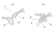
- FIG. 1 It is a fragmentary perspective view which shows an example of the joining structure which concerns on Embodiment 1 of this invention.
- (A) represents a joining loop and a loop hole before joining
- (b) is a partial perspective view showing a joining structure according to the second embodiment.
- 4 is a partial plan view showing an example of a bonding structure in Embodiment 1.
- FIG. It is a plane partial photograph which shows the junction structure in Embodiment 1 of this invention. It is sectional drawing which shows the joining structure in the both ends of the textile fabric in Embodiment 2 of this invention.
- (A) is a figure which shows the whole joining structure
- (b) is a loop for joining formed by upper surface side warp
- (c) is a loop hole formed by lower surface side warp
- (c) is upper surface side warp
- D shows the loop hole at the other end formed by the lower surface side warp.
- the joint structure of the industrial fabric according to the present invention forms a loop by bending and folding a part or all of the warp constituting the fabric at both ends, and the core wire when the loop at one end is joined.
- a joining loop that forms a common hole through which the joining loop faces the joining loop, and a loop at the other end that is paired with the joining loop is fitted and locked. And a loop hole that does not pass through the core wire.
- the joining loop refers to one or more holes arranged in parallel to the machine running direction of the fabric through which the core wire inserted when the endless fabric is made endless. That is, it means a loop that forms a common hole for inserting a core wire or the like, and does not mean a folded warp that has only a function of pressing the weft at the end.
- the joining loop may be bent in advance so as to form a loop in a substantially vertical direction. This is because it is easier to insert the core wire. Then, the warp ends of the woven fabric may be bent and folded, and the warp ends folded into a plurality of wefts may be knitted.
- the warp yarn that is usually folded back in a loop is woven into the adjacent warp where the normal part (the part of the fabric that is not the joint part, the same shall apply hereinafter) should exist, It is abutted against the adjacent warp that is cut at the part.
- the warp yarns that are folded back by forming a loop may be woven into distant warp portions that are not adjacent to each other, or may be woven between two adjacent warp yarns. Further, even when warp yarns that do not form a joining loop or loop hole are included, they can be woven in the same manner after being folded back to form a stop. Note that warp yarns that do not form a loop may be simply cut at the middle portion or at the end portion of the normal portion without being folded back.
- the loop hole is different from the joining loop, and the core wire is not inserted therethrough.
- the loop hole is one or more loops arranged side by side in the machine running direction of the woven fabric, but is formed by warp at the other end of the woven fabric that is opposed to the joining loop. Will be. It may be formed by bending and bending the end portion of the warp at the other end, and knitting the end portions of the warp that are folded back into a plurality of wefts.
- Such a loop hole has a structure for fitting and locking the joining loop.
- the shape of the joining loop and the loop hole may be any structure as long as the loop hole fits the joining loop.
- the joining loop may be bent in a substantially vertical direction to form a loop
- the loop hole may be bent in a substantially horizontal direction to form a loop.
- the loop hole has a structure that is hooked to the core wire at the time of joining.
- the joining loop through which the core wire is inserted is fitted and fixed in one or more loop holes arranged in parallel in the machine direction. Therefore, it is not necessary to hold a plurality of joining loops side by side. For this reason, the position of the hole in the loop for joining is greatly reduced, so that the work of attaching an endless industrial fabric to a machine and processing it into an endless form is more advanced than conventional joining work. Can be carried out stably and simply. Therefore, it is possible to significantly reduce the time required for the endless work. Moreover, the joining structure of the industrial fabric which concerns on this invention is good also considering all the edge parts of the warp in one end part as a joining loop.
- the entire end of the warp at the other end may be a loop hole.
- a part of the warp yarn at one end portion may be formed by a joining loop or loop hole, and the warp yarn not forming the loop may be simply cut at the middle portion or at the end portion without being folded back.
- the joint structure of industrial fabrics according to the present invention is a structure for joining industrial fabrics having end-like shapes in which wefts and warps are arranged in multiple layers, and part or all ends of warps constituting the fabric are both ends.
- the loop at the other end is a loop hole that can be fitted and locked with the joining loop, and is a loop hole that does not pass through the core wire.
- the present invention is a joining loop having a common hole through which the core wire is inserted when joining the loop formed by the upper surface side warp at one end, and is opposed to the joining loop.
- the loop formed by the upper surface side warp at the other end is a loop hole that does not pass through the core wire having a structure capable of fitting and locking the joining loop
- the loop formed by the lower surface side warp at the other end Is a joining loop having a common hole through which the core wire is inserted during joining
- the loop formed by the lower surface side warp at one end that is opposed to the joining loop and joined at the end is a joint loop.
- It is a loop hole which has a structure in which a loop can be fitted and locked, and does not pass through a core wire.
- the loop for joining by the upper surface side warp and the loop hole by the lower surface side warp are alternately arranged, and the upper surface side warp at the other end portion is adjacent to the loop. It is preferable to alternately arrange the loop holes by and the joining loops by the lower side warp.
- the yarn used in the fabric according to the present invention is not particularly limited and can be freely selected depending on the properties desired for the industrial fabric.
- monofilaments multifilaments, spun yarns, crimped and sublime processed textured yarns, bulky yarns, stretch yarns, processed yarns called taslan yarns, molding yarns, or twisted yarns Threads that are combined, for example, can be used.
- not only the circular cross-sectional shape of the yarn but also a square shape, a rectangular shape such as a star shape, a flat shape, an elliptical shape, and a hollow shape can be used.
- the properties of the yarn can be freely selected, and polyester, nylon, polyphenylene sulfide, polyvinylidene fluoride, polypropylene, aramid, polyetheretherketone, polyethylene naphthalate, cotton, wool, metal and the like can be used.
- copolymers and yarns with various substances blended or contained depending on the purpose may be used.
- the upper weft yarn is made of spun yarn, crimped or sublimated processed yarn, or a soft yarn with a large apparent wire diameter such as a moor yarn, the upper layer surface is likely to be covered with these yarns. It is preferable that the difference between the normal part and the joint part can be approached to the extent that it cannot be seen from the upper layer side.
- the yarn used in the present invention may be selected depending on the application. For example, in addition to monofilament, multifilament, spun yarn, crimped processing, bulky processing, etc., generally textured yarn, bulky yarn, stretch yarn, etc. Processed yarns that are called, or yarns that are combined by combining them can be used. Also, the cross-sectional shape of the yarn is not limited to a circle, but a short yarn such as a square shape or a star shape, an elliptical shape, or a hollow yarn can be used.
- the material of the yarn can also be freely selected, and polyester, polyamide, polyphenylene sulfide, polyvinylidene fluoride, polypro, aramid, polyetheretherketone, polyethylene naphthalate, polytetrafluoroethylene, cotton, wool, metal, etc. are used. it can.
- polyester, polyamide, polyphenylene sulfide, polyvinylidene fluoride, polypro, aramid, polyetheretherketone, polyethylene naphthalate, polytetrafluoroethylene, cotton, wool, metal, etc. are used.
- the upper surface side warp is formed of a fluorine-based resin.
- the core wire inserted through the upper surface side joining loop is formed of a thread formed of a fluororesin.
- a fluororesin may be any composite resin containing fluorine with high antifouling properties.
- ETFE polytetrafluoroethylene resin
- FEP tetrafluoroethylene-hexafluoropropylene copolymer
- PFA tetrafluoroethylene-perfluorovinyl ether copolymer
- PVDF polyvinylidene fluoride
- ETFE ethylene-tetrafluoroethylene copolymer
- ECTFE ethylene-chlorotrifluoroethylene copolymer
- the structure of the woven fabric according to the present invention includes a warp one-ply weft single layer structure, a warp one-ply weft double layer structure, a warp one-ply weft three-ply structure, and the like.
- the industrial fabric employing the fluororesin according to the present invention is preferably a two-layer fabric in which an upper surface side fabric and a lower surface side fabric are connected by a weft binding yarn.
- the binding yarn can be made of a yarn such as PET having a higher strength than the fluororesin or the like.
- the binding yarn as the weft binding yarn, it is possible to employ internal binding in which the binding yarn is not exposed on the surface. That is, it is possible to obtain a greater effect that it is possible to prevent the yarn such as PET from being exposed on the surface of the upper surface side fabric formed only of the fluorine-based resin or the like.
- FIG. 1 is a partial perspective view showing an example of an industrial fabric bonding structure according to the present invention.
- a joining structure 1 according to the present invention includes a joining loop 2 that forms a common hole 3 through which a core wire is inserted during joining, and a loop hole 5 that faces the joining loop 2. It is composed of As shown in FIG. 1B, the loop hole 5 has a structure capable of fitting and locking the joining loop 2.
- the joining loop 2 has a common hole 3 through which a core wire (not shown) is inserted, but the loop hole 5 has a structure in which the joining loop 2 is fitted without passing through the core wire. And thus, the position of the common hole 3 of the joining loop 2 can be fixed by fitting the joining loop 2 into the loop hole 5 at the other end of the opposite fabric.
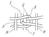
- FIG. 2 is a partial plan view showing an example of the joint structure of industrial fabrics according to the first embodiment.
- a loop 2 is formed by bending the warp yarns 2 and 5 constituting the woven fabric at both ends and turning back, and the loop at one end forms a common hole 3 through which the core wire is inserted during bonding.
- the loop at the other end which is paired with the joining loop 2 at the time of joining, is a loop hole 5 into which the joining loop can be fitted and locked.
- the cored wire 7 is inserted into the common hole 3 to process the endless industrial fabric into an endless fabric. be able to.
- the joining structure of the industrial fabric in Embodiment 1 is a loop in which the joining loop 2 is bent in a substantially vertical direction, and the loop hole 5 is bent in a substantially horizontal direction. It has become a loop.
- reference numeral 8 denotes a weft.
- the ends of the warps 2 and 5 in the woven fabric are bent and folded, and are formed by weaving the ends of the warps that are folded back into the plurality of wefts 8 and 8.
- the joining loop 2 through which the core wire is inserted is fixed in one or more loop holes 5 arranged in parallel in the machine direction. Because the displacement of the hole position is greatly reduced, it is possible to stably and easily perform the work of attaching an endless industrial fabric to a machine and processing it into an endless shape without requiring advanced skills. Become. For this reason, it is possible to greatly reduce the time required for the endless work.
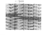
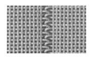
- FIG. 3 is a plane partial photograph showing the bonding structure in Embodiment 1 of the present invention.
- the loop joint shown in FIG. 3 has the industrial fabric joint structure in the first embodiment.
- the endless industrial fabric is mounted on a machine and processed into an endless shape, which is more advanced than the conventional joining structure shown in FIG. It is possible to perform the joining operation stably and simply without requiring any skill, and as a result, the working time can be greatly reduced.
- the industrial fabric according to Embodiment 1 of the present invention is The marking at the joint of the fabric can be greatly reduced as compared with the prior art.
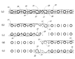
- FIG. 4 is a cross-sectional view showing an example of the industrial fabric bonding structure 10 according to the present invention.
- A is a figure which shows the whole joining structure 10
- (b) is the loop 11 for joining formed with the upper surface side warp 14
- (c) is the loop hole 25 formed with the lower surface side warp 16
- (d ) Shows a joining loop hole 21 at the other end formed by the upper surface side warp 14, and (e) shows a joining loop 15 at the other end formed by the lower surface side warp 16.
- an industrial fabric joining structure 10 comprises an upper surface side warp 14 and a lower surface side warp 16, a weft 18, an upper surface side auxiliary weft 20, a lower surface side auxiliary weft 22, and a weft contact. It is formed by weaving with the binding yarn 26.
- the structure of each warp is as follows. As shown in FIG. 4B, the loop formed by the upper surface side warp 14 at one end is a joining loop 11 having a common hole 12 through which the core wire 17 is inserted when joining.
- the upper surface side warp 14 is made of a fluorine resin. Further, as shown in FIG. 4 (d), a loop formed by the upper surface side warp 14 at the other end that is paired with the joining loop 11 is engaged with the joining loop 11. It is a loop hole 21 that does not pass through the core wire 17 having a structure that can be stopped.
- the loop formed by the lower surface side warp 16 at the other end is a joining loop 15 having a common hole 22 through which the core wire 27 is inserted when joining.
- the loop formed by the lower surface side warp 16 at one end that is opposed to the joining loop 15 can be fitted into and locked with the joining loop 15.
- the loop hole 25 has a structure and does not pass through the core wire 27.
- the lower surface side warp 16 is made of polyester having excellent rigidity.
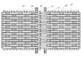
- FIG. 5 is a plan view showing a joint structure according to Embodiment 2 of the present invention.
- the loop joint shown in FIG. 5 has the industrial fabric joint structure in the second embodiment.
- the joining structure of the industrial fabric according to the present invention is a joining loop 11 having a common hole through which the core wire 17 is inserted when the loop formed by the upper surface side warp 14 at one end portion is joined. is there.
- the upper surface side warp 14 is made of a fluorine resin.
- a core wire having a structure in which the loop formed by the upper surface side warp 14 at the other end that is paired with the joining loop 11 can be fitted and locked is inserted through the core wire. It is a loop hole 21 that does not.
- the structure of the lower surface side warp cannot be seen, but it is formed as described with reference to FIGS. 4C and 4E, and a joining structure in which the core wire 27 is inserted is formed.
- the lower surface side warp is made of polyester having excellent rigidity.
- the upper surface side warp is formed of a fluorine resin antifouling function
- the lower surface side warp is formed of polyester having excellent rigidity. Further, it is possible to prevent contamination on the surface of the woven fabric at the bonded portion without reducing the bonding strength.
Landscapes
- Engineering & Computer Science (AREA)
- Textile Engineering (AREA)
- Mechanical Engineering (AREA)
- Woven Fabrics (AREA)
- Paper (AREA)
Abstract
Priority Applications (4)
| Application Number | Priority Date | Filing Date | Title |
|---|---|---|---|
| CA2909238A CA2909238C (fr) | 2013-07-23 | 2014-06-03 | Structure de liaison d'un tissu industriel |
| US14/907,133 US10392729B2 (en) | 2013-07-23 | 2014-06-03 | Binding structure of industrial fabric |
| EP14828996.0A EP3026161B1 (fr) | 2013-07-23 | 2014-06-03 | Tissu industriel avec structure d'assemblage |
| JP2015528181A JP5923667B2 (ja) | 2013-07-23 | 2014-06-03 | 工業用織物の接合構造 |
Applications Claiming Priority (2)
| Application Number | Priority Date | Filing Date | Title |
|---|---|---|---|
| JP2013-152184 | 2013-07-23 | ||
| JP2013152184 | 2013-07-23 |
Publications (1)
| Publication Number | Publication Date |
|---|---|
| WO2015011992A1 true WO2015011992A1 (fr) | 2015-01-29 |
Family
ID=52393046
Family Applications (1)
| Application Number | Title | Priority Date | Filing Date |
|---|---|---|---|
| PCT/JP2014/064697 Ceased WO2015011992A1 (fr) | 2013-07-23 | 2014-06-03 | Structure d'assemblage d'un textile industriel |
Country Status (5)
| Country | Link |
|---|---|
| US (1) | US10392729B2 (fr) |
| EP (1) | EP3026161B1 (fr) |
| JP (1) | JP5923667B2 (fr) |
| CA (1) | CA2909238C (fr) |
| WO (1) | WO2015011992A1 (fr) |
Families Citing this family (1)
| Publication number | Priority date | Publication date | Assignee | Title |
|---|---|---|---|---|
| MX360007B (es) * | 2012-12-27 | 2018-10-11 | Nippon Filcon Kk | Tela industrial bicapa. |
Citations (4)
| Publication number | Priority date | Publication date | Assignee | Title |
|---|---|---|---|---|
| JPS57106797U (fr) * | 1980-12-19 | 1982-07-01 | ||
| JPS5917798U (ja) * | 1982-07-21 | 1984-02-03 | 大和紡績株式会社 | 抄紙用ドライヤ−カンバスにおける継手部 |
| JP3938817B2 (ja) | 1999-02-16 | 2007-06-27 | 日本フイルコン株式会社 | 工業用織物の接合用ループとこのループを用いた接合部 |
| JP2013036157A (ja) | 2011-07-12 | 2013-02-21 | Nippon Filcon Co Ltd | 工業用多層織物の接合用ループ構造 |
Family Cites Families (2)
| Publication number | Priority date | Publication date | Assignee | Title |
|---|---|---|---|---|
| JP4079402B2 (ja) * | 1999-04-05 | 2008-04-23 | 日本フイルコン株式会社 | 工業用織物の接合部 |
| US6776878B2 (en) * | 2002-04-02 | 2004-08-17 | Albany International Corp. | Laminated multiaxial press fabric |
-
2014
- 2014-06-03 JP JP2015528181A patent/JP5923667B2/ja not_active Expired - Fee Related
- 2014-06-03 WO PCT/JP2014/064697 patent/WO2015011992A1/fr not_active Ceased
- 2014-06-03 EP EP14828996.0A patent/EP3026161B1/fr active Active
- 2014-06-03 US US14/907,133 patent/US10392729B2/en active Active
- 2014-06-03 CA CA2909238A patent/CA2909238C/fr active Active
Patent Citations (4)
| Publication number | Priority date | Publication date | Assignee | Title |
|---|---|---|---|---|
| JPS57106797U (fr) * | 1980-12-19 | 1982-07-01 | ||
| JPS5917798U (ja) * | 1982-07-21 | 1984-02-03 | 大和紡績株式会社 | 抄紙用ドライヤ−カンバスにおける継手部 |
| JP3938817B2 (ja) | 1999-02-16 | 2007-06-27 | 日本フイルコン株式会社 | 工業用織物の接合用ループとこのループを用いた接合部 |
| JP2013036157A (ja) | 2011-07-12 | 2013-02-21 | Nippon Filcon Co Ltd | 工業用多層織物の接合用ループ構造 |
Also Published As
| Publication number | Publication date |
|---|---|
| JP5923667B2 (ja) | 2016-05-24 |
| JPWO2015011992A1 (ja) | 2017-03-02 |
| US20160168765A1 (en) | 2016-06-16 |
| US10392729B2 (en) | 2019-08-27 |
| EP3026161A4 (fr) | 2017-03-29 |
| EP3026161A1 (fr) | 2016-06-01 |
| CA2909238C (fr) | 2020-07-07 |
| CA2909238A1 (fr) | 2015-01-29 |
| EP3026161B1 (fr) | 2020-05-13 |
Similar Documents
| Publication | Publication Date | Title |
|---|---|---|
| JP5937838B2 (ja) | 工業用多層織物の接合用ループ構造 | |
| US9458559B2 (en) | Multi-layer fabric | |
| EP2230340A2 (fr) | Tissu résistant à la chaleur et à la corrosion | |
| MXPA06012463A (es) | Tela industrial de dos capas. | |
| CA2308883C (fr) | Habillage de machine a papier, particulierement comme toile secheuse | |
| US20100132825A1 (en) | Industrial two-layer fabric | |
| JP4400925B2 (ja) | 工業用二層織物 | |
| CA2336504C (fr) | Boucle de jonction en tissu industriel et piece de jonction faisant appel a la boucle | |
| US7896035B2 (en) | Industrial multilayer fabric having a narrowing weft | |
| RU2434090C2 (ru) | Многослойная ткань с парными скрепляющими нитями, образующими переплетения по разным профилям | |
| JP5777826B2 (ja) | 工業用二層織物 | |
| JP2004156164A (ja) | 工業用多層織物 | |
| JP5923667B2 (ja) | 工業用織物の接合構造 | |
| WO2015015895A1 (fr) | Tissu industriel formé par un tissu à chaîne double et à trame unique | |
| CA2798992C (fr) | Structure a boucles de raccordement de structure textile plane multicouche industrielle | |
| JP4266782B2 (ja) | 工業用織物 | |
| JP6475063B2 (ja) | 製紙用シームフェルト | |
| JP4394563B2 (ja) | 工業用織物の織り継ぎ方法及びそれにより織り継がれた無端状工業用織物 | |
| JP5839719B2 (ja) | 工業用織物 | |
| JP2017172063A (ja) | 工業用織物 |
Legal Events
| Date | Code | Title | Description |
|---|---|---|---|
| ENP | Entry into the national phase |
Ref document number: 2015528181 Country of ref document: JP Kind code of ref document: A |
|
| WWE | Wipo information: entry into national phase |
Ref document number: 2014828996 Country of ref document: EP |
|
| ENP | Entry into the national phase |
Ref document number: 2909238 Country of ref document: CA |
|
| 121 | Ep: the epo has been informed by wipo that ep was designated in this application |
Ref document number: 14828996 Country of ref document: EP Kind code of ref document: A1 |
|
| WWE | Wipo information: entry into national phase |
Ref document number: 14907133 Country of ref document: US |
|
| NENP | Non-entry into the national phase |
Ref country code: DE |