WO2015012011A1 - Récipient sous forme de poche et procédé de fabrication de ce dernier - Google Patents
Récipient sous forme de poche et procédé de fabrication de ce dernier Download PDFInfo
- Publication number
- WO2015012011A1 WO2015012011A1 PCT/JP2014/065474 JP2014065474W WO2015012011A1 WO 2015012011 A1 WO2015012011 A1 WO 2015012011A1 JP 2014065474 W JP2014065474 W JP 2014065474W WO 2015012011 A1 WO2015012011 A1 WO 2015012011A1
- Authority
- WO
- WIPO (PCT)
- Prior art keywords
- trunk
- closing
- joint portion
- film material
- joining
- Prior art date
- Legal status (The legal status is an assumption and is not a legal conclusion. Google has not performed a legal analysis and makes no representation as to the accuracy of the status listed.)
- Ceased
Links
Images




Classifications
-
- B—PERFORMING OPERATIONS; TRANSPORTING
- B65—CONVEYING; PACKING; STORING; HANDLING THIN OR FILAMENTARY MATERIAL
- B65D—CONTAINERS FOR STORAGE OR TRANSPORT OF ARTICLES OR MATERIALS, e.g. BAGS, BARRELS, BOTTLES, BOXES, CANS, CARTONS, CRATES, DRUMS, JARS, TANKS, HOPPERS, FORWARDING CONTAINERS; ACCESSORIES, CLOSURES, OR FITTINGS THEREFOR; PACKAGING ELEMENTS; PACKAGES
- B65D75/00—Packages comprising articles or materials partially or wholly enclosed in strips, sheets, blanks, tubes or webs of flexible sheet material, e.g. in folded wrappers
- B65D75/28—Articles or materials wholly enclosed in composite wrappers, i.e. wrappers formed by associating or interconnecting two or more sheets or blanks
-
- B—PERFORMING OPERATIONS; TRANSPORTING
- B31—MAKING ARTICLES OF PAPER, CARDBOARD OR MATERIAL WORKED IN A MANNER ANALOGOUS TO PAPER; WORKING PAPER, CARDBOARD OR MATERIAL WORKED IN A MANNER ANALOGOUS TO PAPER
- B31B—MAKING CONTAINERS OF PAPER, CARDBOARD OR MATERIAL WORKED IN A MANNER ANALOGOUS TO PAPER
- B31B50/00—Making rigid or semi-rigid containers, e.g. boxes or cartons
- B31B50/26—Folding sheets, blanks or webs
- B31B50/28—Folding sheets, blanks or webs around mandrels, e.g. for forming bottoms
- B31B50/30—Folding sheets, blanks or webs around mandrels, e.g. for forming bottoms the mandrels moving
- B31B50/32—Folding sheets, blanks or webs around mandrels, e.g. for forming bottoms the mandrels moving in circular paths
- B31B50/324—Folding sheets, blanks or webs around mandrels, e.g. for forming bottoms the mandrels moving in circular paths the mandrels being parallel to the axis of a drum
-
- B—PERFORMING OPERATIONS; TRANSPORTING
- B31—MAKING ARTICLES OF PAPER, CARDBOARD OR MATERIAL WORKED IN A MANNER ANALOGOUS TO PAPER; WORKING PAPER, CARDBOARD OR MATERIAL WORKED IN A MANNER ANALOGOUS TO PAPER
- B31B—MAKING CONTAINERS OF PAPER, CARDBOARD OR MATERIAL WORKED IN A MANNER ANALOGOUS TO PAPER
- B31B50/00—Making rigid or semi-rigid containers, e.g. boxes or cartons
- B31B50/74—Auxiliary operations
- B31B50/81—Forming or attaching accessories, e.g. opening devices, closures or tear strings
- B31B50/84—Forming or attaching means for filling or dispensing contents, e.g. valves or spouts
-
- B—PERFORMING OPERATIONS; TRANSPORTING
- B65—CONVEYING; PACKING; STORING; HANDLING THIN OR FILAMENTARY MATERIAL
- B65D—CONTAINERS FOR STORAGE OR TRANSPORT OF ARTICLES OR MATERIALS, e.g. BAGS, BARRELS, BOTTLES, BOXES, CANS, CARTONS, CRATES, DRUMS, JARS, TANKS, HOPPERS, FORWARDING CONTAINERS; ACCESSORIES, CLOSURES, OR FITTINGS THEREFOR; PACKAGING ELEMENTS; PACKAGES
- B65D75/00—Packages comprising articles or materials partially or wholly enclosed in strips, sheets, blanks, tubes or webs of flexible sheet material, e.g. in folded wrappers
- B65D75/52—Details
- B65D75/58—Opening or contents-removing devices added or incorporated during package manufacture
- B65D75/5861—Spouts
- B65D75/5872—Non-integral spouts
- B65D75/5877—Non-integral spouts connected to a planar surface of the package wall
-
- B—PERFORMING OPERATIONS; TRANSPORTING
- B31—MAKING ARTICLES OF PAPER, CARDBOARD OR MATERIAL WORKED IN A MANNER ANALOGOUS TO PAPER; WORKING PAPER, CARDBOARD OR MATERIAL WORKED IN A MANNER ANALOGOUS TO PAPER
- B31B—MAKING CONTAINERS OF PAPER, CARDBOARD OR MATERIAL WORKED IN A MANNER ANALOGOUS TO PAPER
- B31B2100/00—Rigid or semi-rigid containers made by folding single-piece sheets, blanks or webs
- B31B2100/002—Rigid or semi-rigid containers made by folding single-piece sheets, blanks or webs characterised by the shape of the blank from which they are formed
- B31B2100/0022—Rigid or semi-rigid containers made by folding single-piece sheets, blanks or webs characterised by the shape of the blank from which they are formed made from tubular webs or blanks, including by tube or bottom forming operations
-
- B—PERFORMING OPERATIONS; TRANSPORTING
- B31—MAKING ARTICLES OF PAPER, CARDBOARD OR MATERIAL WORKED IN A MANNER ANALOGOUS TO PAPER; WORKING PAPER, CARDBOARD OR MATERIAL WORKED IN A MANNER ANALOGOUS TO PAPER
- B31B—MAKING CONTAINERS OF PAPER, CARDBOARD OR MATERIAL WORKED IN A MANNER ANALOGOUS TO PAPER
- B31B2105/00—Rigid or semi-rigid containers made by assembling separate sheets, blanks or webs
- B31B2105/002—Making boxes characterised by the shape of the blanks from which they are formed
- B31B2105/0022—Making boxes from tubular webs or blanks, e.g. with separate bottoms, including tube or bottom forming operations
-
- B—PERFORMING OPERATIONS; TRANSPORTING
- B31—MAKING ARTICLES OF PAPER, CARDBOARD OR MATERIAL WORKED IN A MANNER ANALOGOUS TO PAPER; WORKING PAPER, CARDBOARD OR MATERIAL WORKED IN A MANNER ANALOGOUS TO PAPER
- B31B—MAKING CONTAINERS OF PAPER, CARDBOARD OR MATERIAL WORKED IN A MANNER ANALOGOUS TO PAPER
- B31B2110/00—Shape of rigid or semi-rigid containers
- B31B2110/20—Shape of rigid or semi-rigid containers having a curved cross section, e.g. circular
-
- B—PERFORMING OPERATIONS; TRANSPORTING
- B31—MAKING ARTICLES OF PAPER, CARDBOARD OR MATERIAL WORKED IN A MANNER ANALOGOUS TO PAPER; WORKING PAPER, CARDBOARD OR MATERIAL WORKED IN A MANNER ANALOGOUS TO PAPER
- B31B—MAKING CONTAINERS OF PAPER, CARDBOARD OR MATERIAL WORKED IN A MANNER ANALOGOUS TO PAPER
- B31B2120/00—Construction of rigid or semi-rigid containers
- B31B2120/10—Construction of rigid or semi-rigid containers provided with covers, e.g. lids
-
- B—PERFORMING OPERATIONS; TRANSPORTING
- B31—MAKING ARTICLES OF PAPER, CARDBOARD OR MATERIAL WORKED IN A MANNER ANALOGOUS TO PAPER; WORKING PAPER, CARDBOARD OR MATERIAL WORKED IN A MANNER ANALOGOUS TO PAPER
- B31B—MAKING CONTAINERS OF PAPER, CARDBOARD OR MATERIAL WORKED IN A MANNER ANALOGOUS TO PAPER
- B31B50/00—Making rigid or semi-rigid containers, e.g. boxes or cartons
- B31B50/02—Feeding or positioning sheets, blanks or webs
- B31B50/10—Feeding or positioning webs
-
- B—PERFORMING OPERATIONS; TRANSPORTING
- B31—MAKING ARTICLES OF PAPER, CARDBOARD OR MATERIAL WORKED IN A MANNER ANALOGOUS TO PAPER; WORKING PAPER, CARDBOARD OR MATERIAL WORKED IN A MANNER ANALOGOUS TO PAPER
- B31B—MAKING CONTAINERS OF PAPER, CARDBOARD OR MATERIAL WORKED IN A MANNER ANALOGOUS TO PAPER
- B31B50/00—Making rigid or semi-rigid containers, e.g. boxes or cartons
- B31B50/14—Cutting, e.g. perforating, punching, slitting or trimming
- B31B50/16—Cutting webs
-
- B—PERFORMING OPERATIONS; TRANSPORTING
- B31—MAKING ARTICLES OF PAPER, CARDBOARD OR MATERIAL WORKED IN A MANNER ANALOGOUS TO PAPER; WORKING PAPER, CARDBOARD OR MATERIAL WORKED IN A MANNER ANALOGOUS TO PAPER
- B31B—MAKING CONTAINERS OF PAPER, CARDBOARD OR MATERIAL WORKED IN A MANNER ANALOGOUS TO PAPER
- B31B50/00—Making rigid or semi-rigid containers, e.g. boxes or cartons
- B31B50/60—Uniting opposed surfaces or edges; Taping
- B31B50/64—Uniting opposed surfaces or edges; Taping by applying heat or pressure, e.g. by welding
- B31B50/642—Uniting opposed surfaces or edges; Taping by applying heat or pressure, e.g. by welding using sealing jaws or sealing dies
-
- B—PERFORMING OPERATIONS; TRANSPORTING
- B31—MAKING ARTICLES OF PAPER, CARDBOARD OR MATERIAL WORKED IN A MANNER ANALOGOUS TO PAPER; WORKING PAPER, CARDBOARD OR MATERIAL WORKED IN A MANNER ANALOGOUS TO PAPER
- B31B—MAKING CONTAINERS OF PAPER, CARDBOARD OR MATERIAL WORKED IN A MANNER ANALOGOUS TO PAPER
- B31B50/00—Making rigid or semi-rigid containers, e.g. boxes or cartons
- B31B50/60—Uniting opposed surfaces or edges; Taping
- B31B50/64—Uniting opposed surfaces or edges; Taping by applying heat or pressure, e.g. by welding
- B31B50/644—Making seals parallel to the direction of movement, i.e. longitudinal sealing
Definitions
- an inner bag to be used in an outer container such as a container or a drum can
- a barrel member made of a film material formed in a cylindrical shape and a top plate at a portion bent inward in the radial direction on the upper end side of the barrel member
- a bottom plate is joined to a portion bent inward in the radial direction on the lower end side of the body member
- Patent Document 3 a manufacturing method of this inner bag, the lower half part of the cylindrical body made of a film material is folded inward to form a double cylinder, and the upper ends of the inner cylinder and the outer cylinder in the double cylinder are respectively in the radial direction.
- the inner bags described in Patent Documents 3 and 4 are used by being accommodated in a large outer container such as a container or a drum can, and the inner bags themselves are not self-supporting.
- the inner peripheral edges of the upper and lower end portions of the barrel member that are bent inward are exposed in the bag, in order to enhance the functionality of the barrel member such as gas barrier properties and light shielding properties,
- the adhesive laminated on the multilayer film melts into the contents from the inner peripheral edge exposed in the bag, and the contents deteriorate or the contents are adhesive. There is a problem that the film penetrates into the layers and the film peels between the layers.
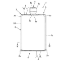
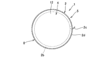
- a pouch container according to the present invention is a self-supporting pouch container provided with a body member made of a film material and upper and lower closing members made of a film material that respectively close the upper end portion and the lower end portion of the body member.
- Each of the upper and lower ends of the body member is formed with an annular body-side end joint that is bent inward, and the outer periphery of the upper and lower closure members is joined to the upper and lower body-side end joints, respectively.
- the upper and lower ends of the body member are closed with upper and lower closing members.
- a film material does not have a strict meaning regarding thickness but shall be used as a general term including a sheet material.
- the inner member is made of a single layer film or a multilayer film that does not use an adhesive
- the outer peripheral edge of the inner member is exposed in the container, but a multilayer film manufactured by a dry laminating method is used.
- a multilayer film manufactured by a dry laminating method is used.
- the adhesive from melting from the outer peripheral edge of the inner member to the contents filled in the container.
- the inner periphery of the inner end of the cylinder side end joint is covered so as not to be exposed in the container, the container can be filled even when a multilayer film manufactured by a dry laminate method is used as the cylinder member. It is possible to reliably prevent the adhesive from melting from the inner peripheral edge of the trunk side end joint portion with respect to the contents that have been made.
- One of the outer member and the inner member is made of a film material capable of closing the opening of the trunk member, and the other of the outer member and the inner member is the trunk side end joint, the outer member, and the inner member. It is a preferred embodiment that it is made of an annular film material joined to one of the above. In this case, since the other of the outer member and the inner member is made of an annular film material, the amount of the synthetic resin material constituting the pouch container can be minimized.
- an annular body side first end joint portion that is folded inward is sandwiched between a first joint head and a mandrel, and the body side first end joint portion is temporarily fixed in a folded state.
- the annular body side second end joint portion folded inward is sandwiched between the second joint head and the receiving jig, and the body side second end joint portion is folded.
- Providing a step of temporarily fixing is also a preferred embodiment.
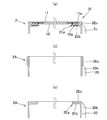
- the lower end closing member 4 is composed of an inner member 12 and an outer member 13 made of a film material, and the outer peripheral portions of the inner member 12 and the outer member 13 of the lower end closing member 4 are the inner surface side and the outer surface side of the trunk side lower end joint portion 2b. It is joined to.
- the film material constituting the body member 2 and the outer members 11 and 13 is composed of a soft film having a single layer or a multilayer structure that can be reduced in volume by hand. Although it can be composed of a single layer film, it provides adhesive barriers such as dry lamination, wet lamination, hot melt lamination, single lamination, and tandem lamination to provide functions such as gas barrier properties, light shielding properties, and scratch resistance. And multilayer films produced by coextrusion methods such as extrusion lamination such as coextrusion lamination, thermal lamination, T-die method, and inflation method. In particular, in the present invention, the end portions of the body member 2 and the outer members 11 and 13 are not exposed in the pouch container 1, and the adhesive constituting the film material can be prevented from melting into the contents.
- the trunk member 2 in order to make the trunk member 2 easy to fold, it is possible to form a plurality of crease lines extending in the vertical direction in the middle of the circumferential direction of the trunk member 2 or to form gussets.
- the body member 2 is formed in a cylindrical shape by rounding one film material into a cylindrical shape and joining both ends thereof, but the two film materials are overlapped to join the side portions. It is also possible to employ a body member 2 formed by joining two or more film materials. Furthermore, it is also possible to employ a tubular inflation film formed by inflation molding as the film material constituting the trunk member 2, and in this case, the trunk member 2 without the trunk side side joint portion 2c can be manufactured. .
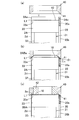
- the upper end closing structure 7 will be described. As shown in FIGS. 1 to 4, the upper end portion of the body member 2 is bent inwardly to be bent inwardly, thereby forming an endless annular flange-like body side upper end joint portion 2a. Is provided. An inner member made of a ring-shaped film material having an outer diameter substantially the same as the inner diameter of the upper end portion of the trunk member 2 and an inner diameter larger than that of the flange portion 6b of the spout 6 is provided on the lower side of the upper end joint portion 2a. 10 is provided, and an outer member 11 made of a circular film material having substantially the same diameter as the outer diameter of the upper end portion of the barrel member 2 is provided above the barrel side upper end joint portion 2a.
- the upper end closing member 3 that closes the upper end opening of the body member 2 is configured.
- the inner joint portion 10a and the outer joint portion 11a in this manner, the upper end portion of the pouch container 1 can be double sealed, and even if a joint failure occurs in the inner joint portion 10a, the outer side It is comprised so that sealing performance can be ensured by the junction part 11a.
- the inner member 10 and the outer member 11 can be joined over the entire surface inside the inner peripheral edge of the annular trunk side upper end joining portion 2a, or can be configured not to be joined. Moreover, it joins between the junction part of the inner side member 10 and the outer side member 11, the junction part of the inner side member 10 and the trunk
- the inner member 10 and the outer member 11 are joined to the synthetic resin layer on the inner surface side of the trunk member 2, so that the sealant layer on the outer surface side is used as a film material constituting the trunk member 2. It is possible to use the omitted film material having a two-layer structure.
- the width W3 of the trunk side lower end joint portion 2b is preferably set to 2 mm to 20 mm.
- the thickness of the sealant layer of the soft film constituting the body member 2, the inner member 12, and the outer member 13 is preferably set to 10 ⁇ m to 200 ⁇ m so that the films can be reliably bonded without poor sealing. .
- the thickness of the film material of the inner member 12 may be the same as the thickness of the film material of the outer member 13, but in order to minimize the amount of synthetic resin material used, the thickness of the film material of the outer member 13 Also, it is preferable to form a thin wall. However, in this case, it is preferable that the lower end opening of the body member 2 be closed by at least the outer member 13.
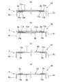
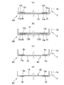
- the inner member 12 and the outer member 13 are formed in a disk shape, but instead of the inner member 12 as in the lower end closing structure 8A shown in FIG.
- An inner member 12A made of an annular film material having a width capable of covering the inner peripheral edge of the portion 2b is provided, and the inner member 12A and the outer member 13 are arranged on the inner side so as to cover the inner peripheral edge of the lower end joint portion 2b.
- the member 12A is joined, or instead of the outer member 13, it is made of an annular film material having a width capable of covering the inner peripheral edge of the trunk side lower end joining portion 2b.
- the outer member 13B and to join the outer member 13B across the trunk side lower end joint portion 2b and the inner member 12 so as to cover the inner periphery of the trunk side lower end joint portion 2b.
- the inner member 12 is omitted, and the lower end opening is closed by the lower end closing member 4C formed only of the outer member 13, or the lower end shown in FIG. 7D.
- the outer member 13 may be omitted, and the lower end opening may be closed with the lower end closing member 4D including only the inner member 12.
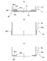
- annular inner folded portion 2Ee bent inward instead of the trunk side lower end joining portion 2b, at the lower end portion of the trunk member 2, and an inner folded portion A body-side lower end joining portion 2Ed composed of an annular outer folding portion 2Ef obtained by folding the outer peripheral edge of 2Ee outward is formed, and the outer peripheral portion of the inner member 12 is joined to the lower side of the inner folding portion 2Ee. It is also possible to join the outer peripheral part of the inner member 12 and the outer peripheral part of the outer member 13 inside the trunk side lower end joint part 2Ed by joining the outer peripheral part to the lower side of the outer folding part 2Ef.
- a lower end portion of a cylindrical body member 2A as shown in FIG. 10 is folded outward, and an outer folding portion 2Ef is formed as shown in FIG. 8B.
- the body member 2A is manufactured, and then the outer folding part 2Ef and the inner folding part are folded inwardly as shown in FIG.
- a body member 2A having an annular body side lower end joining portion 2Ed made of 2Ee is manufactured, and then the outer peripheral portions of the inner member 12 and the outer member 13 are overlapped and joined to the body side lower end joining portion 2Ed.
- a lower end closing structure 8E as shown in FIG. 8A is formed.
- the inner member 12 and the outer member 13 are joined to the synthetic resin layer on the inner surface side of the trunk member 2, so that the sealant layer on the outer surface side is used as a film material constituting the trunk member 2. It is possible to use the omitted film material having a two-layer structure.
- the lower end closing structure 8 formed by joining the outer peripheral portions of the inner member 12 and the outer member 13 to the trunk side lower end joint portion 2b does not protrude outward from the container body 5, the outer periphery of the inner member 12 and the outer member 13
- the design of the pouch container 1 can be prevented from deteriorating due to the outer portion and the trunk side lower end joint 2b projecting outward from the trunk member 2.
- the upper end portion of the container body 5 is provided with a trunk side upper end joining portion 2a, an outer member 11, and an inner member 10, and the upper surface of the pouch container 1 is reinforced, so that the shape retaining property of the pouch container 1 is improved.
- the handling property of the pouch container 1 can be improved.
- the body member 2 and the upper end closing member 3 are made of a film material, after use of the contents, the body member 2 and the upper end closing member 3 can be flattened to reduce the volume of the pouch container 1. Become.
- the upper end closing structure 7 formed by joining the outer peripheral portions of the inner member 10 and the outer member 11 to the trunk side upper end joint portion 2a does not protrude outward from the container body 5, the inner member 10 and the outer member 11 It is possible to prevent the design of the pouch container 1 from being deteriorated due to the outer peripheral part or the trunk side upper end joint part 2a projecting outward from the trunk member 2.
- the body member forming step for forming the body member 2A and the upper end portion (this corresponds to the first end portion) of the body member 2A is bent inward so as not to join the middle part in the longitudinal direction, and the upper end on the annular body side
- the joint portion 2a (which corresponds to the trunk side first end joint portion) is formed, and the outer peripheral portion of the upper end closing member 3 (which corresponds to the first closing member) made of a film material to which the spout 6 is joined in advance is defined as the trunk side.
- An upper end closing step (this corresponds to the first closing step) for manufacturing the barrel member 2B bonded to the upper end joining portion 2a and closing the upper end opening, and a lower end portion (second end portion) of the barrel member 2B inside Bent to the annular barrel side lower end joint 2b (this is the barrel 2) (corresponding to the second end joining portion), and the outer peripheral portion of the lower end closing member 4 (which corresponds to the second closing member) made of a film material is used as the trunk side lower end joining portion 2b (trunk side second end joining portion).
- the lower end closing step (this corresponds to the second closing step) for producing the pouch container 1A having the body member 2C with the lower end opening closed, and the overlapping portion 20 of the body member 2C of the pouch container 1A.
- the upper end closing member 3 can be joined to the upper end portion of the trunk member in the upper end closing step.
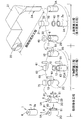
- the material film 21 is fed out from the roll 22, the material film 21 is rolled into a cylindrical shape and the inner surfaces of both end portions thereof face each other and overlap each other. Then, after joining the overlapping portions 20 by heat sealing or ultrasonic sealing at regular intervals, the material film is cut at the central portion in the length direction of the joining portions, so that A cylindrical body member 2 ⁇ / b> A is formed in which joint portions 20 a are formed at both ends, and non-joint portions 20 b that are not joined are formed in the middle portion of the overlapping portion 20 in the length direction.
- the length of the joint portion 20a is set to be longer than the length in the radial direction of the trunk side upper end joint portion 2a and the trunk side lower end joint portion 2b.
- the claw member 81 of the chuck means 80 is configured to hold the joint portion 20a.
- the length of the non-joining portion 20b between the upper and lower joining portions 20a is such that the receiving jig body 63 of the receiving jig 61 (see FIG. 13) is inserted into the body member 2C through the opening formed by the non-joining portion 20b. The length is set so that it can be inserted.
- the cylindrical body member 2A is bent into a polygonal shape.
- one specific overlapping portion 20 only both end portions in the length direction are bonded to form the bonding portion 20a, and other overlapping portions are bonded over the entire length.
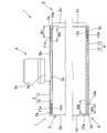
- the mandrel 31 used in the upper end closing process will be described. As shown in FIGS. 9, 11, and 12, the mandrel 31 is attached to and detached from the column member 32 erected on the rotary table 30 and the upper end portion of the column member 32. And a head member 33 provided as possible. The outer peripheral edge of the head member 33 is disposed outside the outer peripheral edge of the column member 32, and the head member 33 is configured to be fitted into the inner surface of the body member 2A without a substantial gap. It is also preferable to form an air suction passage in the mandrel 31 and open the air passage so that the body member 2 and the inner member 10 can be sucked and held.
- the trunk member 2 ⁇ / b> A is vertically removed with respect to the mandrel 31 so that the trunk-side upper end joint 2 ⁇ / b> Aa is disposed on the upper side.
- the boundary portion L1 between the body portion 2d of the body member 2A and the body side upper end joint portion 2Aa connected to the body portion 2A is positioned at the bending corner portion 33a on the outer periphery of the upper end of the head member 33 of the mandrel 31.
- the body member 2A is externally fitted and held on the mandrel 31, and the ring-shaped inner member 10 is positioned and placed on the mandrel 31 inside the body-side upper end joint 2Aa.
- the tapered surface 41 of the first folding member 40 is pressed against the folding corner 33a of the mandrel 31 with the boundary portion L1 of the body member 2A interposed therebetween.
- the first folding member is formed so that the trunk-side upper end joint portion 2 ⁇ / b> Aa is folded inward to form a truncated cone-shaped barrel-side upper end joint portion 2 ⁇ / b> ABa and the folded state is maintained.
- the first joining head 42 is fitted inside, the first folding member 40 is sandwiched between the first joining head 42 and the mandrel 31, and is temporarily fixed by heat sealing, ultrasonic sealing or the like, and extends to the inner peripheral side.
- the body member 2BA is manufactured by temporarily fixing the annular body side upper end joint portion 2a in the folded state.
- the first folding member 40 is formed of a ring-shaped member, and a tapered surface 41 having a diameter increasing toward the lower side is formed on the inner peripheral surface of the lower end.
- the tapered surface 41 is formed in a continuous annular shape in the same shape as the bending corner 33a so that the middle portion in the width direction faces the bending corner 33a of the mandrel 31. If the inclination angle ⁇ 1 of the taper surface 41 with respect to the horizontal plane is too large, the folding angle of the trunk side upper end joint portion 2ABa becomes shallow, and if it is too small, the end portion of the trunk side upper end joint portion 2Aa is smoothly moved to the inner peripheral side by the taper surface 41.
- the inclination angle ⁇ 1 is preferably set to 15 ° to 75 °.
- the wrinkle extending in the radial direction is formed in the body side upper end joint portion 2ABa when bent inward, the top surface outer peripheral portion of the taper surface 41 and the mandrel 31 is circumferentially arranged with the top portion and the trough portion of the wave portion. It is also preferable that the wrinkles are formed so as to be alternately arranged, and the wrinkles are formed beautifully at regular intervals in the circumferential direction.
- the first joining head 42 is configured to be able to be fitted into the first folding member 40 with almost no gap, and the trunk-side upper end joining portion 2 a in which the first joining head 42 is folded inward.
- the wrinkles of the upper end joint 2a on the cylinder side are bonded to each other by heat sealing, ultrasonic sealing, etc.
- the upper end joint portion 2a can be brazed in a state of being folded inward and temporarily fixed.
- the guide member 43 is a cylindrical guide member 43 that can be externally fitted to the body member 2BA, and the guide surface increases in diameter toward the upper inner peripheral surface.
- the guide member 43 formed with 43a is used, and the outer member 11 to which the spout 6 is previously attached is guided by the guide surface 43a in a state in which the guide member 43 is fitted on the upper portion of the body member 2BA set on the mandrel 31.
- the outer member 11 is loaded into the guide member 43 and positioned on the body member 2BA.
- a joining plate 45 that is fitted into the guide member 43 without a substantial gap is inserted, and the upper end joining portion 2a, the inner member 10, and the outer peripheral portion of the outer member 11 are inserted. Is sandwiched between the upper end surface of the mandrel 31 and the joining plate 45, and the inner member 10 and the outer member 11 are joined to the trunk-side upper-end joined portion 2a by heat sealing or ultrasonic sealing, and the trunk-side upper-end joined portion.
- the body member 2B is manufactured by joining the outer peripheral part of the inner member 10 and the outer peripheral part of the outer member 11 inside 2a, and joining the upper end closing member 3 to the upper end part.
- the upper end closing member 3 is constituted only by the outer member 11
- the placement of the inner member 10 on the mandrel 31 in the trunk member setting step is omitted.
- the inner member 10 to which the spout 6 is attached in advance is set on the mandrel 31, and the outer member setting step is omitted.
- the mandrel 31 is first set in the setting step while rotating the receiving jig 61 provided at the outer peripheral portion of the rotary table 60 at a circumferential interval with the rotary table 60.
- the barrel member 2B extracted from the barrel member 2B is set upside down on the receiving jig 61, and the inner member 12 is set on the receiving jig 61.
- the cylindrical barrel side lower end joining portion 2Ab of the barrel member 2B The outer member 13 is set at an appropriate position on the cylinder side lower end joint portion 2b temporarily fixed in the outer member setting process, and then the inner side is connected to the cylinder side lower end joint section 2b in the bonding process.
- work which joins the outer peripheral part of the member 12 and the outer side member 13 will be performed sequentially.
- the receiving jig 61 includes a J-shaped support rod 62, and a disk-shaped receiving jig main body 63 provided substantially horizontally at the tip of the support rod 62. It has.
- the outer peripheral edge of the receiving jig main body 63 is disposed outside the outer peripheral edge of the support rod 62, and the receiving jig main body 63 is configured to be fitted into the inner surface of the body member 2B with almost no gap. It is also preferable to form an air suction passage in the receiving jig 61 and open the air passage so that the body member 2B and the inner member 12 can be sucked and held.
- the body member 2 ⁇ / b> B is turned upside down so that the body side lower end joint portion 2 ⁇ / b> Ab is disposed on the upper side, and the non-joint portion of the body member 2 ⁇ / b> B 20b is opened, and the receiving jig main body 63 is inserted into the body member 2B from the opening. Then, the boundary portion L2 between the body portion 2d of the body member 2B and the body side lower end joint portion 2Ab connected to the body portion 2B is positioned at the bending corner portion 63a on the outer periphery of the upper end of the receiving jig body 63 of the receiving jig body 63. The body member 2B is fitted and held on the receiving jig 61, and the inner member 12 is placed on the receiving jig main body 63 inside the body-side lower end joint portion 2Ab.
- the tapered surface 71 of the second folding member 70 is brought into pressure contact with the bending corner 63a of the receiving jig 61 across the boundary portion L2 of the body member 2B.
- the cylinder-side lower end joint portion 2Ab is folded inward to form a truncated cone-shaped body-side lower end joint portion 2ABb.
- the second joining head 72 is fitted inside the folding member 70, the second folding member 70 is sandwiched between the second joining head 72 and the receiving jig main body 63, and temporarily fixed by heat sealing or ultrasonic sealing,
- a body member 2CA is manufactured in which an annular body side lower end joint portion 2b extending to the inner peripheral side is temporarily fixed in a folded state.
- the second folding member 70 is a ring-shaped member, and a tapered surface 71 having a diameter increasing toward the lower side is formed on the inner peripheral surface of the lower end.
- the tapered surface 71 is formed in the same shape as the bending corner 63a and in a continuous annular shape so that the middle portion in the width direction faces the bending corner 63a of the receiving jig body 63. . If the inclination angle ⁇ 2 of the tapered surface 71 with respect to the horizontal plane is too large, the folding angle of the trunk side lower end joint portion 2ABb becomes shallow, and if it is too small, the end portion of the trunk side lower end joint portion 2Ab is smoothly moved to the inner peripheral side by the tapered surface 71.
- the inclination angle ⁇ 2 is preferably set to 15 ° to 75 °.
- the wrinkle extending in the radial direction is formed in the body side lower end joint portion 2ABb when bent inward, the outer peripheral portion of the upper surface of the tapered surface 71 and the receiving jig main body 63 and the top portion of the wave portion in the circumferential direction. It is also preferable to form a wave shape so that the valleys are alternately arranged, and to make the wrinkles beautifully formed at regular intervals in the circumferential direction.
- the second joining head 72 is configured to be fitted into the second folding member 70 without a substantial gap, and the trunk side lower end joining portion 2 b in which the second joining head 72 is folded inward.
- the trunk side lower end joint 2b is joined to the inner member 10, and the trunk side lower end joint 2b is folded inward. Can be temporarily fixed by brazing.
- the guide member 73 is a cylindrical guide member 73 that can be externally fitted to the body member 2CA, and increases in diameter toward the upper side on the upper inner peripheral surface.
- the guide member 73 formed with the guide member 73 is used, and the guide member 73 is guided on the guide surface 73a while the outer member 13 is guided by the guide surface 73a in a state where the guide member 73 is externally fitted to the upper portion of the body member 2CA set on the jig body 63. 73, the outer member 13 is positioned and set on the body member 2CA.
- a joining plate 75 that fits inside the guide member 73 without a substantial gap is inserted, and the outer side of the trunk side lower end joining portion 2 b, the inner member 12, and the outer member 13 Is sandwiched between the upper end surface of the receiving jig body 63 and the joining plate 75, and the inner member 12 and the outer member 13 are joined to the trunk side lower end joining portion 2b by heat sealing, ultrasonic sealing, etc.
- the lower end closing member 4 is constituted by only the outer member 13
- the placement of the inner member 12 on the receiving jig main body 63 in the trunk member setting step is omitted.
- the outer member setting step is omitted.
- the pouch container 1A is extracted from the receiving jig 61 and transferred to the next side joining station.
- the side joining step as shown in FIGS. 15A and 15B, the upper and lower joining portions 20a of the pouch container 1A are held by the claw members 81 of the upper and lower chuck means 80 as shown in FIG.
- the upper and lower chuck means 80 are moved away from each other, the upper and lower joints 20a are pulled away from each other, and the opening of the non-joint part 20b is closed.
- the pouch container 1 is obtained by forming the trunk side side joint portion 2 c formed by continuously joining the upper end portion and the lower end portion of the member 2.
- the boundary portion L1 between the body portion 2d of the body member 2A set on the mandrel 31 and the body side upper end joint portion 2Aa connected to the upper end portion of the body portion 2d is used for bending the head member 33.
- the cylinder side upper end joint portion 2Aa is sandwiched between the corner portion 33a and the taper surface 41 of the first folding member 40, and the cylinder side upper end joint portion 2Aa is folded inward by the taper surface 41. Therefore, the cylinder side upper end joint portion 2a is easily and cleanly formed. be able to.
- trunk side upper end joint portion 2a is temporarily fixed so that the folded state of the trunk side upper end joint portion 2a folded inward is maintained, the trunk side upper end joint portion 2a and the inner member 10 and The joining operation with the outer peripheral portion of the outer member 11 can be performed stably and efficiently, and the joining operation of the upper end closing member 3 with respect to the upper end portion of the body member 2A can be easily automated. Further, the boundary portion L2 between the body portion 2d of the body member 2B set on the receiving jig body 63 and the body side lower end joint portion 2Ab provided continuously to the lower end portion of the body portion 2d is folded on the receiving jig body 63.
- the trunk side lower end joint portion 2b can be easily and neatly formed. Can be formed. Moreover, since the trunk
- the upper end of the body member 2A is closed and then the lower end is closed.
- the upper end can be closed after the lower end of the body member 2A is closed.
Landscapes
- Engineering & Computer Science (AREA)
- Mechanical Engineering (AREA)
- Chemical & Material Sciences (AREA)
- Composite Materials (AREA)
- Making Paper Articles (AREA)
- Bag Frames (AREA)
Abstract
La présente invention se rapporte à un récipient sous forme de poche qui présente une meilleure stabilité indépendante et une meilleure stabilité de forme et présente une conception supérieure, qui peut réduire le volume et qui peut garantir suffisamment une étanchéité aux liquides entre un élément de corps et un élément d'étanchéité, et à un procédé de fabrication de ce récipient. Un récipient (1) autoportant sous forme de poche comprend un élément de corps (2) composé d'un matériau de film, ainsi que des éléments d'étanchéité (3, 4) sur la partie supérieure et la partie inférieure qui sont composés d'un matériau de film et qui scellent chacun une ouverture réalisée sur l'extrémité supérieure et sur l'extrémité inférieure de l'élément de corps (2), les extrémités supérieure et inférieure de l'élément de corps (2) étant scellées aux éléments d'étanchéité (3, 4) par formation, à la fois dans l'extrémité supérieure et dans l'extrémité inférieure de l'élément de corps (2), de joints d'extrémité (2a, 2b) côté corps annulaire qui sont pliés vers l'intérieur et par jonction des circonférences externes des éléments d'étanchéité supérieur et inférieur (3, 4) à chaque joint d'extrémité (2a, 2b) côté corps.
Applications Claiming Priority (2)
| Application Number | Priority Date | Filing Date | Title |
|---|---|---|---|
| JP2013-151438 | 2013-07-22 | ||
| JP2013151438A JP2015020787A (ja) | 2013-07-22 | 2013-07-22 | パウチ容器及びその製造方法 |
Publications (1)
| Publication Number | Publication Date |
|---|---|
| WO2015012011A1 true WO2015012011A1 (fr) | 2015-01-29 |
Family
ID=52393064
Family Applications (1)
| Application Number | Title | Priority Date | Filing Date |
|---|---|---|---|
| PCT/JP2014/065474 Ceased WO2015012011A1 (fr) | 2013-07-22 | 2014-06-11 | Récipient sous forme de poche et procédé de fabrication de ce dernier |
Country Status (2)
| Country | Link |
|---|---|
| JP (1) | JP2015020787A (fr) |
| WO (1) | WO2015012011A1 (fr) |
Families Citing this family (5)
| Publication number | Priority date | Publication date | Assignee | Title |
|---|---|---|---|---|
| JP6781205B2 (ja) * | 2018-06-25 | 2020-11-04 | 藤森工業株式会社 | 容器 |
| JP7497963B2 (ja) * | 2019-06-07 | 2024-06-11 | 藤森工業株式会社 | 容器 |
| WO2020004387A1 (fr) * | 2018-06-25 | 2020-01-02 | 藤森工業株式会社 | Contenant |
| JP2021008310A (ja) | 2019-07-02 | 2021-01-28 | 藤森工業株式会社 | 容器 |
| JP7082168B2 (ja) * | 2020-10-15 | 2022-06-07 | 藤森工業株式会社 | 容器 |
Citations (4)
| Publication number | Priority date | Publication date | Assignee | Title |
|---|---|---|---|---|
| JPS3625090Y1 (fr) * | 1959-06-16 | 1961-09-25 | ||
| JPS5944329U (ja) * | 1982-09-16 | 1984-03-23 | 株式会社リングストン | 二重底を備えた防水性手提袋 |
| JP3119795U (ja) * | 2005-12-26 | 2006-03-09 | 日新産商株式会社 | 合成樹脂袋 |
| WO2012017938A1 (fr) * | 2010-08-05 | 2012-02-09 | 日本山村硝子株式会社 | Contenant et procédé de fabrication de celui-ci |
-
2013
- 2013-07-22 JP JP2013151438A patent/JP2015020787A/ja active Pending
-
2014
- 2014-06-11 WO PCT/JP2014/065474 patent/WO2015012011A1/fr not_active Ceased
Patent Citations (4)
| Publication number | Priority date | Publication date | Assignee | Title |
|---|---|---|---|---|
| JPS3625090Y1 (fr) * | 1959-06-16 | 1961-09-25 | ||
| JPS5944329U (ja) * | 1982-09-16 | 1984-03-23 | 株式会社リングストン | 二重底を備えた防水性手提袋 |
| JP3119795U (ja) * | 2005-12-26 | 2006-03-09 | 日新産商株式会社 | 合成樹脂袋 |
| WO2012017938A1 (fr) * | 2010-08-05 | 2012-02-09 | 日本山村硝子株式会社 | Contenant et procédé de fabrication de celui-ci |
Also Published As
| Publication number | Publication date |
|---|---|
| JP2015020787A (ja) | 2015-02-02 |
Similar Documents
| Publication | Publication Date | Title |
|---|---|---|
| CN104736446B (zh) | 袋状容器 | |
| JP7138091B2 (ja) | 軟包材容器用中間材の製造方法、軟包材容器の製造方法及び軟包材容器包装体の製造方法 | |
| JP2017534534A (ja) | 容器 | |
| JP7203553B2 (ja) | 角底包装袋、包装体、および角底包装袋の製造方法 | |
| JP6854157B2 (ja) | 軟包材容器用中間材、軟包材容器の製造方法及び軟包材容器包装体の製造方法 | |
| JP6947597B2 (ja) | 紙容器 | |
| JP2015020787A (ja) | パウチ容器及びその製造方法 | |
| EP3674073A1 (fr) | Procédé et appareil de fabrication de récipients en forme de poche à bec verseur | |
| JP2003276741A (ja) | 自立袋及びその製造方法 | |
| JP5488756B1 (ja) | パウチ容器 | |
| AU2017361365B2 (en) | Self-standing bag and method for manufacturing same | |
| JP2018024472A (ja) | スパウト付きガゼット袋形成用のガゼット袋体 | |
| CN110753663B (zh) | 带嘴包装袋及其制造方法、以及装有内容物的带嘴包装袋 | |
| JP4316368B2 (ja) | 自立袋およびその製造方法 | |
| JP2015196513A (ja) | パウチ容器、及びパウチ容器の製造方法 | |
| JP5049537B2 (ja) | 自立袋 | |
| JP2013244974A (ja) | パウチ容器 | |
| JP4448578B2 (ja) | ボトム付き袋状容器 | |
| JP6626317B2 (ja) | スパウト付きガゼット袋およびその製造方法 | |
| JP6111784B2 (ja) | パウチ容器の製造方法 | |
| JP2016069032A (ja) | パウチ容器及びその製造方法 | |
| JP2014198581A (ja) | パウチ容器 | |
| JP7229320B2 (ja) | 自立袋 | |
| JP2018039569A (ja) | スパウト付きガゼット袋形成用のガゼット袋体の製造方法 | |
| JP2019189288A (ja) | 内袋及びその製造方法 |
Legal Events
| Date | Code | Title | Description |
|---|---|---|---|
| 121 | Ep: the epo has been informed by wipo that ep was designated in this application |
Ref document number: 14830290 Country of ref document: EP Kind code of ref document: A1 |
|
| NENP | Non-entry into the national phase |
Ref country code: DE |
|
| 122 | Ep: pct application non-entry in european phase |
Ref document number: 14830290 Country of ref document: EP Kind code of ref document: A1 |