WO2015012015A1 - Dispositif d'affichage de dessin et procédé d'affichage de dessin - Google Patents
Dispositif d'affichage de dessin et procédé d'affichage de dessin Download PDFInfo
- Publication number
- WO2015012015A1 WO2015012015A1 PCT/JP2014/065753 JP2014065753W WO2015012015A1 WO 2015012015 A1 WO2015012015 A1 WO 2015012015A1 JP 2014065753 W JP2014065753 W JP 2014065753W WO 2015012015 A1 WO2015012015 A1 WO 2015012015A1
- Authority
- WO
- WIPO (PCT)
- Prior art keywords
- pixel
- border
- target pixel
- search area
- priority
- Prior art date
- Legal status (The legal status is an assumption and is not a legal conclusion. Google has not performed a legal analysis and makes no representation as to the accuracy of the status listed.)
- Ceased
Links
Images






Classifications
-
- G—PHYSICS
- G06—COMPUTING OR CALCULATING; COUNTING
- G06T—IMAGE DATA PROCESSING OR GENERATION, IN GENERAL
- G06T11/00—Two-dimensional [2D] image generation
- G06T11/20—Drawing from basic elements
- G06T11/23—Drawing from basic elements using straight lines or curves
Definitions
- the present invention relates to a drawing display device and a drawing display method for displaying a drawing object on an image.
- Patent Document 1 describes a data transfer apparatus that speeds up processing time by data palette conversion and transparency processing.
- the reference data storage unit converts display data into display data when an instruction to display the same display position as that of other display data is acquired for image data stored in a predetermined address space.
- Reference data for determining whether to display the image data by overwriting is stored
- the data conversion unit converts the image data into display image data
- the transmission determination unit converts the pixel value of the display image data Then, it is determined whether or not the pixel value of the reference data matches.
- the data transfer unit transfers the display image data to the display address space when it is determined that the pixel value of the display image data matches the pixel value of the reference data.
- a border When displaying a drawing object on an image, a border may be added along the outline of the drawing object in addition to palette conversion and transparency processing. For example, when a figure is displayed on a pattern, a border is created by drawing a figure outline in a color different from that of the figure (see paragraph 0017 of Patent Document 2).
- a drawing process using a border line is performed on the contact portion (see paragraph 0015 of Patent Document 5).
- the border is drawn on the outline of the graphic displayed above, and the border is not drawn on the graphic below.
- the overlapping portion is determined by a drawing graphic description including information on elemental graphics such as line segments and dots constituting the priority order of overlapping and the graphic (see, for example, paragraph 0023 of Patent Document 4).
- the outline of the figure may be subjected to anti-aliasing processing.
- the ratio of the area occupied by each straight line to each pixel is calculated based on the vertical separation distance with respect to the straight line, and the pixel color and the frame buffer color are mixed and drawn on the display device based on the occupation ratio (Patent Document 3). (See paragraphs 0032-0044).
- the bordering is generally performed by determining the edge of the drawing object using a CPU (Central Processing Unit) or a GPU (Graphics Processing Unit) and converting the edge pixels.
- the graphic and image rendering processing is performed by dedicated hardware (see Patent Document 6), but when drawing a figure, the figure outline is drawn thickly to create a border.
- JP 2007-80106 A Japanese Patent Laid-Open No. 06-110442 Japanese Patent Application Laid-Open No. 06-274641 JP 10-049690 A JP-A-10-111955 Japanese National Patent Publication No. 11-505644
- the present invention has been made in view of the above-described circumstances, and an object of the present invention is to speed up a drawing process when a drawing object is framed and displayed on an image.
- a drawing display device provides: A priority order acquisition unit that acquires priority order information indicating the order of display of drawing objects displayed in one image; A setting unit that sets the priority of the drawing object to which the pixel belongs to each pixel of the drawing object with reference to the priority information; An edge determination unit that determines the target pixel as an edge pixel when there is a pixel having a higher priority than the target pixel in a search area of a predetermined range including the target pixel of interest in the image; A replacement unit that replaces the pixel determined to be the border pixel by the border determination unit with a pixel of a predetermined border color; It is characterized by providing.
- a drawing display method includes: A priority order acquisition step of acquiring priority order information indicating the order of display of drawing objects to be displayed in one image; A setting step of referring to the priority information and setting the priority of the drawing object to which the pixel belongs to each pixel of the drawing object; An edge determination step for determining the target pixel as an edge pixel when there is a pixel having a higher priority than the target pixel in a search area of a predetermined range including the target pixel of interest in the image; A replacement step of replacing the pixel determined as the border pixel in the border determination step with a pixel of a predetermined border color; It is characterized by providing.
- the drawing process when a plurality of drawing objects are bordered and displayed on one image, the drawing process can be accelerated.
- FIG. 2A It is a block diagram which shows the structural example of the drawing display apparatus which concerns on Embodiment 1 of this invention. It is a figure which shows the example of the drawing object without a border. It is a figure which shows the border of the drawing object of FIG. 2A. It is a figure which shows the state which attached the border to the drawing object of FIG. 2A. It is a figure which shows the example of the drawing object which has an overlapping part without a border. It is a figure which shows the example of the drawing object which has the overlapping part which determined the boundary of a background and an object, and added the border. It is a figure which shows the example which adds a border to the drawing object arrange
- FIG. 6 is a diagram illustrating an example of a search area according to Embodiment 1.
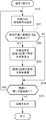
- FIG. 6 is a flowchart illustrating an example of a drawing operation according to the first embodiment.
- 6 is a flowchart showing an example of an operation of border display according to the first embodiment.
- It is a block diagram which shows the structural example of the drawing display apparatus which concerns on Embodiment 2 of this invention.
- It is a figure which shows the example of the weighted search area
- FIG. 10 is a flowchart showing an example of an operation of border display according to the second embodiment.
- 12 is a flowchart illustrating an example of an operation of border display according to the third embodiment.
- FIG. 1 is a block diagram showing a configuration example of a drawing display apparatus according to Embodiment 1 of the present invention.
- the drawing display device 1 of the present invention is a device including a monitor 16 for displaying an image such as the terminal device 10, reads a drawing object from the video memory 13, generates image data with a border on the drawing object, and generates a monitor 16. To display. Whether the drawing object is to be trimmed can be set from a CPU (Central Processing Unit) 11 or a GPU (Graphics Processing Unit) 12.
- CPU Central Processing Unit
- GPU Graphics Processing Unit
- the terminal device 10 includes a CPU 11, a GPU 12, a video memory 13, a display control circuit 15, and a monitor 16.
- the GPU 12, the video memory 13, and the display control circuit 15 are connected to the CPU 11 via the internal bus 14.
- the CPU 11 controls the entire terminal device 10.
- the CPU 11 selects an image file to be displayed on the monitor 16 and instructs the GPU 12.
- the GPU 12 expands a rendering object of a raster object or a vector object included in the commanded image file as pixel data constituting an image in the video memory 13.
- the display control circuit 15 reads out the pixel data from the video memory 13, generates image data with a border on the drawing object, and displays the image data on the monitor 16.
- the drawing display device 1 includes a GPU 12 and a display control circuit 15.
- the GPU 12 includes a priority setting unit 2.
- the display control circuit 15 includes a data reading unit 3, a border determination unit 4, and a replacement unit 5.
- FIG. 2A to 2C are diagrams showing an example of the border of a drawing object.
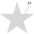
- FIG. 2A shows an example of a drawing object without a border.
- FIG. 2B shows a border of the drawing object of FIG. 2A.
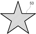
- FIG. 2C shows a state in which the drawing object of FIG. 2A is trimmed.
- the CPU 11 or the GPU 12 may attach the border 52 as shown in FIG. 2B to the drawing object 51 as shown in FIG. 2A to obtain the bordered drawing object 53 as shown in FIG. 2C.
- the time for drawing the border may be equal to or longer than the time for drawing the borderless drawing object, and the drawing time increases due to the border.
- the drawing display device 1 reads out the pixel data from the video memory 13 and at the same time attaches a border.
- the drawing display device 1 includes a GPU 12, a priority order setting unit 2, a data reading unit 3, an edge determination unit 4, and a replacement unit 5.
- the GPU 12 obtains drawing object priority information from the CPU 11 and develops (draws) the drawing object in the video memory 13 in accordance with the drawing object priority.
- the priority order information is included in the image file.
- the drawing objects are developed in the video memory 13 in order from the lowest priority. In the overlapping part of the drawing objects, the pixels of the drawing object having a higher priority are overwritten, and the drawing objects are displayed on the image according to the priority.
- the priority setting unit 2 sets the priority of the drawing object to which the pixel belongs to each pixel of the drawing object. That is, each pixel data includes priority order data of a drawing object to which the pixel belongs. Since the pixel data is overwritten in order from the lower priority, the priority of the drawing object to which the pixel to be finally displayed belongs is set.
- the method of developing the drawing object in the video memory 13 is not limited to the method described above.
- the priority order of the pixels already written and the priority order of the pixels to be drawn may be compared, and the drawing may be overwritten if it is higher and not written if it is lower.
- the priority order of the drawing object to which the displayed pixel belongs may be set to that pixel.
- the priority order of the pixel data may be stored by expanding the bits of the pixel data, or may be stored using a part of the bits of the existing pixel data. For example, when RGBA transparency (A) information is not used for image display, bits assigned to transparency can be used for storing priority.
- RGBA transparency (A) information is not used for image display, bits assigned to transparency can be used for storing priority.
- the data reading unit 3 reads the pixel data from the video memory 13 and sends it to the border determination unit 4. As described above, priority order data indicating the display order of the drawing objects is added to the pixel data. The boundary where the drawing object is displayed can be identified from the priority order of the pixel data.
- 3A to 3C are diagrams showing examples of drawing objects having overlapping portions.
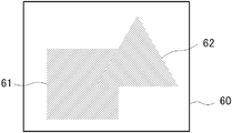
- a square drawing object 61 and a triangular drawing object 62 are arranged in the background 60.
- the background 60 is also a drawing object.
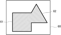
- the background 60 has the lowest priority and is arranged on the rearmost surface, then the rectangular drawing object 61 has the highest priority, and the triangular drawing object 62 has the highest priority. It can be said that the lower priority is arranged on the back side of the image, and the higher priority is arranged on the front side of the image. If the border of the background and the object is simply determined and the border is added to the drawing object of FIG. 3A, the border is not added to the border of the overlapping portion of the square drawing object 61 and the triangular object 62 as shown in FIG. 3B. .
- priority order information is added to pixel data when an object is drawn.
- a border is added not only to the boundary between the background and the object but also to the periphery of the drawing object having a high priority in the overlapping portion of the drawing objects.
- a triangular drawing is placed on the square drawing object 61 as shown in FIG. 3C.
- a border is added to the triangular drawing object 62 arranged in front of the higher priority in the overlapping portion.
- the border determination unit 4 in FIG. 1 scans a search area within a predetermined range including the target pixel by moving the search area so that pixels included in the image to be displayed are sequentially set as the target pixel, and is included in the search area. It is determined using the pixel data whether the target pixel is a border pixel. The border determination unit 4 determines that the target pixel is a border pixel when there is a pixel having a higher priority than the target pixel in a search area within a predetermined range including the target pixel of interest.
- the search area is a closed area (single connection) that includes the target pixel and that the pixels continue vertically and horizontally (there are no separated pixels).
- the size of the search area is set according to the width of the border.
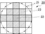
- FIG. 4 is a diagram illustrating an example of a search area according to the first embodiment.
- the pixel 22 with hatching intersecting at the center indicates the position of the target pixel.
- the search area 20 is, for example, a pixel included in a circle 21 whose diameter is a size obtained by adding one pixel to the width of the border centering on the target pixel (pixel 22).
- the search area 20 in FIG. 4 is an example when the border width is 4 pixels. In the example of FIG. 4, twelve pixels 23 with hatched hatching constitute the search area 20.
- the border determination unit 4 moves the search area 20 in the image so that the pixels of the image to be displayed are sequentially set as target pixels (pixels 22), and the search area 20 (pixels 23) for each target pixel (pixel 22). Whether or not the target pixel (pixel 22) is a border pixel is determined based on whether or not there is a pixel having a higher priority than the target pixel. If there is a pixel having a higher priority than the target pixel (pixel 22) in the search area, the target pixel (pixel 22) is determined as a border pixel. If there is no pixel having a higher priority than the target pixel (pixel 22) in the search area, the target pixel is a non-framing pixel.
- the border judgment unit 4 in FIG. 1 sends the result of border judgment to the replacement unit 5.
- the replacement unit 5 replaces the border pixel with the pixel of the predetermined border color and causes the monitor 16 to display the image.
- the border color is not limited to one color for the entire image. For example, a different color may be used for each drawing object. Further, a different color may be used for each region in the image. In addition, gradation can be added with one drawing object.
- the display control circuit 15 can be composed of, for example, a shift register of pixel data corresponding to the search area and a circuit that calculates from each data of the shift register. For example, it is possible to determine whether or not the target pixel is a border pixel by comparing the priority order of the data of the target pixel of the shift register with other data and taking a logical sum.
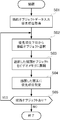
- FIG. 5 is a flowchart showing an example of the drawing operation according to the first embodiment.
- the GPU 12 inputs the drawing object data and acquires the priority order of the drawing objects (step S01).
- a drawing object is selected from a drawing object having a lower priority (step S02).
- the selected drawing object is developed (drawn) in the video memory 13 (step S03).
- the priority order setting unit 2 sets the priority order of the drawing object to the drawn pixels (step S04).
- step S05 If there is a drawing object to be developed in the video memory 13 (step S05; YES), the process returns to step S02, selects a lower one of the remaining drawing objects, and repeats the processing up to step S04. If there is no drawing object to be developed (step S05; NO), the drawing process is terminated.
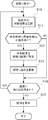
- FIG. 6 is a flowchart showing an example of the border display operation according to the first embodiment.
- the data reading unit 3 of the display control circuit 15 selects a target pixel in the image from the video memory 13 (step S10). For example, pixel data corresponding to the search area including the target pixel is read into a shift register corresponding to the search area 20 as shown in FIG.
- step S11 If there is a pixel having a higher priority than the target pixel in the search area (step S11; YES), the border determination unit 4 sets the target pixel as a border pixel (step S12). Then, the replacement unit 5 replaces the color value of the target pixel (border pixel) with the determined border color (step S13). If there is no pixel having a higher priority than the target pixel in the search area (step S11; NO), step S12 and step S13 are skipped.
- step S14 If there is a remaining pixel to be selected as the target pixel in the image (step S14; YES), the process returns to step S10 to select the next target pixel. For example, the next pixel data is read into each row of the aforementioned shift register. Then, the above process is repeated. If there is no remaining pixel to be selected as the target pixel in the image (step S14; NO), an image in which the border pixel is replaced is displayed on the monitor 16 (step S15).
- each pixel is mechanically determined in the search area using the priority information of the drawing objects, a plurality of drawing objects are trimmed.
- the drawing process can be speeded up.
- a border can be added to a drawing object having a high priority in a portion where drawing objects overlap.
- the drawing display device 1 of the first embodiment it is possible to eliminate the need for the CPU 11 or the GPU 12 to draw a border for an object drawing that requires a border. Thereby, the effect of reducing the load on the CPU 11 and the GPU 12 is obtained. Although there is no change in the used memory bandwidth from the drawing display device 1 to the video memory 13 according to the first embodiment, the access to the video memory 13 from the CPU 11 or the GPU 12 is reduced. The effect to raise is also acquired.
- the border width is 4 pixels, but the border width can be changed by changing the size of the search area 20.
- the search area 20 is not limited to a symmetric shape with the target pixel as the center as shown in FIG. The search area may not be circular. If the search area is biased with respect to the target pixel, a biased border can be added to the drawing object.
- the configuration of the drawing display device 1 is not limited to the GPU 12 and the display control circuit 15.
- the priority setting unit 2 and the display control circuit 15 can be used as the drawing display device 1 by separating the processing for developing the drawing object in the video memory 13 by the GPU 12 and the processing for setting the priority setting for each pixel.
- the display control circuit 15 can be incorporated into the GPU 12 so that the GPU 12 can also serve as the drawing display device 1.
- Embodiment 2 In Embodiment 1, since the border color is always a fixed color, jaggy may be noticeable depending on the drawing object.
- the border color and the blending process are applied to the border color in accordance with the occupancy rate of the search area in the target drawing object or the drawing object having a high priority.
- FIG. 7 is a block diagram showing a configuration example of a drawing display apparatus according to Embodiment 2 of the present invention.
- the border determination unit 4 includes an occupation rate calculation unit 6.
- the occupancy rate calculation unit 6 calculates the occupancy rate of the search area of the drawing object having a higher priority with respect to the target pixel, using the weighting coefficient assigned to each pixel position in the search area.
- the replacement unit 5 replaces the border pixel with a pixel having a color value obtained by multiplying the border color by the occupation ratio.
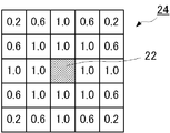
- FIG. 8 is a diagram illustrating an example of a weighted search area according to the second embodiment.
- a weighting coefficient is set at the position of the pixel included in the search area 24.
- a weighting coefficient of 1.0 is set for the pixel that is completely included in the position of the pixel 23 in the search area 20 of FIG. 4, that is, the distance of the border width (circle 21).
- a weighting coefficient of 0.6 or 0.2 is set according to the area partially included in the distance of the border width (a pixel is applied to the circle 21).
- the occupancy ratio calculation unit 6 uses, for example, the weighting coefficient assigned to each pixel position in the search area 24, and calculates, for example, the sum of the weighting coefficients at the positions of the pixels having higher priority than the target pixel in the search area 24. Calculate as If the target pixel is not a border pixel, there is no pixel having a higher priority than the target pixel in the search area 24, so the occupation ratio is set to zero. When the occupation ratio is not 0, the target pixel can be determined as a border pixel. In the example of FIG. 8, the occupation ratio calculation unit 6 clamps the occupation ratio to 1.0 when the total of the weighting coefficients exceeds 1.0.
- the weighting coefficient included in the search area may be normalized so that the maximum sum of the weighting coefficients at the positions of the pixels having higher priority than the target pixel is 1.
- the pixel with higher priority than the target pixel can be set to 1, and the product sum with the weighting coefficient of the search area can be used as the occupation ratio.
- the method of setting the weighting factor can be determined arbitrarily.
- the occupancy calculation method based on the sum of the weighting coefficients of the positions of the pixels having higher priority than the target pixel in the search area can be arbitrarily set.
- the first embodiment can be regarded as a special case of the second embodiment in which the weighting coefficient is set to 1, and the logical sum of products with pixels having higher priority than the target pixel is calculated as the occupation ratio.
- the replacement unit 5 replaces the border pixel with a pixel having a color value obtained by multiplying the border color by the occupation ratio. As a result, it is possible to add an anti-aliasing effect to the border.
- FIG. 9 is a flowchart showing an example of the border display operation according to the second embodiment.
- step S22 and step S23 are different from step S12 and step S13 of FIG.
- the occupation rate is calculated at the same time as setting the target pixel as a border pixel (step S22).
- the replacement unit 5 replaces the border pixel with a border color pixel and multiplies the occupation rate (step S23). Then, an image composed of drawing pixels and border pixels is displayed on the monitor 16 (step S15).
- the border color is multiplied by the occupancy ratio of the pixel having higher priority than the target pixel in the search area for the target pixel.
- jaggy can be made inconspicuous.
- FIG. 10 is a block diagram showing a configuration example of a drawing display apparatus according to Embodiment 3 of the present invention.
- the replacement unit 5 includes a border color adjusting unit 7.
- Other configurations are the same as those in the first embodiment.
- the border color adjusting unit 7 sets a color value obtained by multiplying the border color by a color value of a pixel having a high priority in the search area for the target pixel as a border color when the target pixel is replaced.
- the border color changes according to a pixel having a higher priority than the target pixel included in the search area.
- the anti-aliasing effect set when the drawing object is expanded is reflected on the border pixels.
- FIG. 11 is a flowchart showing an example of the border display operation according to the third embodiment.
- step S33 is inserted between step S12 and step S13 in FIG.
- the border color adjusting unit 7 of the replacement unit 5 sets the color value of the pixel having a high priority in the search area for the target pixel as the border color.
- the border color is adjusted so as to be the border color when the target pixel is replaced by multiplication (step S33).
- the replacement unit 5 sets the target pixel as a border pixel (step S12).
- Other operations are the same as those in the first embodiment.
- the drawing display device 1 of the third embodiment when the target pixel is set to the border color, the color value of the pixel having a higher priority order than the target pixel included in the search region is adjusted to the color value multiplied by the border color. Therefore, the anti-aliasing effect set for the pixels with high priority can be reflected in the border. As a result, killing the effect of anti-aliased pixels by bordering is avoided.
- the second embodiment and the third embodiment can be implemented together.
- a priority order acquisition unit that acquires priority order information indicating the order of display of drawing objects displayed in one image;
- a setting unit that sets the priority of the drawing object to which the pixel belongs to each pixel of the drawing object with reference to the priority information;
- An edge determination unit that determines the target pixel as an edge pixel when there is a pixel having a higher priority than the target pixel in a search area of a predetermined range including the target pixel of interest in the image;
- a replacement unit that replaces the pixel determined to be the border pixel by the border determination unit with a pixel of a predetermined border color;
- a drawing display device comprising:
- the border determination unit uses the weighting coefficient assigned to each pixel position in the search area when the search area includes a pixel having the higher priority than the target pixel in the search area. Calculate the occupancy rate according to a predetermined criterion based on the sum of the weighting coefficients of the pixel positions with higher ranks, The replacement unit replaces the target pixel with a pixel having a color value obtained by multiplying the border color by the occupation ratio calculated for the target pixel when the target pixel is determined to be the border pixel.
- the replacement unit when there is a pixel having a higher priority than the target pixel in the search area, a color obtained by multiplying the border color by a color value of the pixel having a higher priority in the search area for the target pixel.
- the drawing display device according to appendix 1 or 2, wherein the value is a border color when the target pixel is replaced.
- Appendix 4 The drawing display device according to any one of appendices 1 to 3, wherein the search area is a circle whose diameter is a size obtained by adding one pixel to the width of the border centering on the target pixel.
- a drawing display method comprising:
- the border determination step when there is a pixel having a higher priority than the target pixel in the search area, the priority of the search area is determined using a weighting coefficient assigned to each pixel position of the search area. Calculate the occupancy rate according to a predetermined criterion based on the sum of the weighting coefficients of the pixel positions with higher ranks,
- the replacement step when the target pixel is determined to be the border pixel, the target pixel is replaced with a pixel having a color value obtained by multiplying the border color by the occupation ratio calculated for the target pixel.
- Appendix 8 The drawing display method according to any one of appendices 5 to 7, wherein the search area is a circle whose diameter is a size obtained by adding one pixel to the width of the border centering on the target pixel.
Landscapes
- Physics & Mathematics (AREA)
- General Physics & Mathematics (AREA)
- Engineering & Computer Science (AREA)
- Theoretical Computer Science (AREA)
- Image Generation (AREA)
- Processing Or Creating Images (AREA)
- Editing Of Facsimile Originals (AREA)
- Controls And Circuits For Display Device (AREA)
Abstract
La vitesse d'un processus de dessin augmente lorsqu'un objet de dessin est doté d'une frontière et est affiché dans une image. La GPU (12) acquiert des informations d'ordre de priorité indiquant l'ordre d'affichage d'image d'un objet de dessin affiché dans une image. Une unité de définition d'ordre de priorité (2), lors de l'agrandissement de l'objet de dessin dans une mémoire vidéo (13) par référence aux informations d'ordre de priorité, définit, pour chaque pixel de l'objet de dessin, un ordre de priorité de l'objet de dessin auquel le pixel appartient. S'il existe un pixel ayant un ordre de priorité plus élevé qu'un pixel intéressant dans une région de recherche d'une plage déterminée contenant le pixel intéressant de l'image agrandie dans la mémoire visuelle (13), une unité de détermination de frontière (4) détermine que le pixel intéressant est un pixel de frontière. Une unité de remplacement (5) remplace le pixel qui a été déterminé par l'unité de détermination de frontière (4) comme étant le pixel de frontière par un pixel d'une couleur de frontière déterminée.
Applications Claiming Priority (2)
| Application Number | Priority Date | Filing Date | Title |
|---|---|---|---|
| JP2013154781A JP5892618B2 (ja) | 2013-07-25 | 2013-07-25 | 描画表示装置および描画表示方法 |
| JP2013-154781 | 2013-07-25 |
Publications (1)
| Publication Number | Publication Date |
|---|---|
| WO2015012015A1 true WO2015012015A1 (fr) | 2015-01-29 |
Family
ID=52393068
Family Applications (1)
| Application Number | Title | Priority Date | Filing Date |
|---|---|---|---|
| PCT/JP2014/065753 Ceased WO2015012015A1 (fr) | 2013-07-25 | 2014-06-13 | Dispositif d'affichage de dessin et procédé d'affichage de dessin |
Country Status (2)
| Country | Link |
|---|---|
| JP (1) | JP5892618B2 (fr) |
| WO (1) | WO2015012015A1 (fr) |
Citations (3)
| Publication number | Priority date | Publication date | Assignee | Title |
|---|---|---|---|---|
| JPS58169281A (ja) * | 1982-03-30 | 1983-10-05 | Fujitsu Ltd | 縁取りパタ−ン作成装置 |
| JPS6220068A (ja) * | 1985-07-19 | 1987-01-28 | Canon Inc | 画像情報変換方式 |
| JP2007245657A (ja) * | 2006-03-17 | 2007-09-27 | Konica Minolta Business Technologies Inc | 画像処理方法、画像形成装置、およびコンピュータプログラム |
-
2013
- 2013-07-25 JP JP2013154781A patent/JP5892618B2/ja not_active Expired - Fee Related
-
2014
- 2014-06-13 WO PCT/JP2014/065753 patent/WO2015012015A1/fr not_active Ceased
Patent Citations (3)
| Publication number | Priority date | Publication date | Assignee | Title |
|---|---|---|---|---|
| JPS58169281A (ja) * | 1982-03-30 | 1983-10-05 | Fujitsu Ltd | 縁取りパタ−ン作成装置 |
| JPS6220068A (ja) * | 1985-07-19 | 1987-01-28 | Canon Inc | 画像情報変換方式 |
| JP2007245657A (ja) * | 2006-03-17 | 2007-09-27 | Konica Minolta Business Technologies Inc | 画像処理方法、画像形成装置、およびコンピュータプログラム |
Also Published As
| Publication number | Publication date |
|---|---|
| JP2015026198A (ja) | 2015-02-05 |
| JP5892618B2 (ja) | 2016-03-23 |
Similar Documents
| Publication | Publication Date | Title |
|---|---|---|
| US10885607B2 (en) | Storage for foveated rendering | |
| US10331448B2 (en) | Graphics processing apparatus and method of processing texture in graphics pipeline | |
| KR20180122048A (ko) | 스크린 위치에 따라 달라지는 분해능을 가진 다수의 렌더 타겟을 위한 텍스처 매핑을 위한 그라디언트 조정 | |
| KR20190100194A (ko) | 타일식 아키텍처들에서의 포비티드 렌더링 | |
| WO2015032185A1 (fr) | Système et procédé de reconfiguration de super-résolution d'image | |
| CN108122196B (zh) | 图片的纹理贴图方法和装置 | |
| JP6485068B2 (ja) | 画像処理方法および画像処理装置 | |
| JP4370438B2 (ja) | ベクター画像描画装置、ベクター画像描画方法およびプログラム | |
| CN103650004B (zh) | 图像处理装置、图像处理方法及集成电路 | |
| JP6135937B2 (ja) | 画像処理方法および画像処理装置 | |
| JP5892618B2 (ja) | 描画表示装置および描画表示方法 | |
| JP7801008B2 (ja) | 画像のアンチエイリアシング方法、装置、機器、及びコンピュータプログラム | |
| US10970817B2 (en) | Image magnifying apparatus | |
| US20100020096A1 (en) | Antialiasing apparatus | |
| JP2008160345A (ja) | 画像処理装置及び画像処理方法、並びにコンピュータ・プログラム | |
| JP4801088B2 (ja) | 画素サンプリングの方法及び装置 | |
| KR102470242B1 (ko) | 영상 처리 장치, 영상 처리 방법, 및 프로그램 | |
| JP6575742B2 (ja) | 画像処理方法および画像処理装置 | |
| JP4325812B2 (ja) | ベクター画像描画回路およびベクター画像描画方法 | |
| US20160321835A1 (en) | Image processing device, image processing method, and display device | |
| JP2016095667A (ja) | 画像処理装置および電子機器 | |
| JP2015106318A (ja) | 画像処理装置および画像処理方法 | |
| WO2015173954A1 (fr) | Dispositif de dessin, procédé de dessin et programme d'ordinateur pour dessiner | |
| WO2017104084A1 (fr) | Dispositif de traitement de données, procédé de traitement de données et programme de traitement de données | |
| JP2008166983A (ja) | 解像度変換処理方法、画像処理装置、画像表示装置及びプログラム |
Legal Events
| Date | Code | Title | Description |
|---|---|---|---|
| 121 | Ep: the epo has been informed by wipo that ep was designated in this application |
Ref document number: 14829219 Country of ref document: EP Kind code of ref document: A1 |
|
| NENP | Non-entry into the national phase |
Ref country code: DE |
|
| 122 | Ep: pct application non-entry in european phase |
Ref document number: 14829219 Country of ref document: EP Kind code of ref document: A1 |