WO2015012256A1 - 画像符号化方法、画像符号化装置及び画像符号化プログラム - Google Patents
画像符号化方法、画像符号化装置及び画像符号化プログラム Download PDFInfo
- Publication number
- WO2015012256A1 WO2015012256A1 PCT/JP2014/069296 JP2014069296W WO2015012256A1 WO 2015012256 A1 WO2015012256 A1 WO 2015012256A1 JP 2014069296 W JP2014069296 W JP 2014069296W WO 2015012256 A1 WO2015012256 A1 WO 2015012256A1
- Authority
- WO
- WIPO (PCT)
- Prior art keywords
- pixel
- intra prediction
- encoding
- pseudo
- prediction direction
- Prior art date
- Legal status (The legal status is an assumption and is not a legal conclusion. Google has not performed a legal analysis and makes no representation as to the accuracy of the status listed.)
- Ceased
Links
Images



Classifications
-
- H—ELECTRICITY
- H04—ELECTRIC COMMUNICATION TECHNIQUE
- H04N—PICTORIAL COMMUNICATION, e.g. TELEVISION
- H04N19/00—Methods or arrangements for coding, decoding, compressing or decompressing digital video signals
- H04N19/10—Methods or arrangements for coding, decoding, compressing or decompressing digital video signals using adaptive coding
- H04N19/102—Methods or arrangements for coding, decoding, compressing or decompressing digital video signals using adaptive coding characterised by the element, parameter or selection affected or controlled by the adaptive coding
- H04N19/103—Selection of coding mode or of prediction mode
- H04N19/11—Selection of coding mode or of prediction mode among a plurality of spatial predictive coding modes
-
- H—ELECTRICITY
- H04—ELECTRIC COMMUNICATION TECHNIQUE
- H04N—PICTORIAL COMMUNICATION, e.g. TELEVISION
- H04N19/00—Methods or arrangements for coding, decoding, compressing or decompressing digital video signals
- H04N19/10—Methods or arrangements for coding, decoding, compressing or decompressing digital video signals using adaptive coding
- H04N19/102—Methods or arrangements for coding, decoding, compressing or decompressing digital video signals using adaptive coding characterised by the element, parameter or selection affected or controlled by the adaptive coding
- H04N19/132—Sampling, masking or truncation of coding units, e.g. adaptive resampling, frame skipping, frame interpolation or high-frequency transform coefficient masking
-
- H—ELECTRICITY
- H04—ELECTRIC COMMUNICATION TECHNIQUE
- H04N—PICTORIAL COMMUNICATION, e.g. TELEVISION
- H04N19/00—Methods or arrangements for coding, decoding, compressing or decompressing digital video signals
- H04N19/10—Methods or arrangements for coding, decoding, compressing or decompressing digital video signals using adaptive coding
- H04N19/134—Methods or arrangements for coding, decoding, compressing or decompressing digital video signals using adaptive coding characterised by the element, parameter or criterion affecting or controlling the adaptive coding
- H04N19/146—Data rate or code amount at the encoder output
- H04N19/147—Data rate or code amount at the encoder output according to rate distortion criteria
-
- H—ELECTRICITY
- H04—ELECTRIC COMMUNICATION TECHNIQUE
- H04N—PICTORIAL COMMUNICATION, e.g. TELEVISION
- H04N19/00—Methods or arrangements for coding, decoding, compressing or decompressing digital video signals
- H04N19/10—Methods or arrangements for coding, decoding, compressing or decompressing digital video signals using adaptive coding
- H04N19/169—Methods or arrangements for coding, decoding, compressing or decompressing digital video signals using adaptive coding characterised by the coding unit, i.e. the structural portion or semantic portion of the video signal being the object or the subject of the adaptive coding
- H04N19/17—Methods or arrangements for coding, decoding, compressing or decompressing digital video signals using adaptive coding characterised by the coding unit, i.e. the structural portion or semantic portion of the video signal being the object or the subject of the adaptive coding the unit being an image region, e.g. an object
- H04N19/176—Methods or arrangements for coding, decoding, compressing or decompressing digital video signals using adaptive coding characterised by the coding unit, i.e. the structural portion or semantic portion of the video signal being the object or the subject of the adaptive coding the unit being an image region, e.g. an object the region being a block, e.g. a macroblock
-
- H—ELECTRICITY
- H04—ELECTRIC COMMUNICATION TECHNIQUE
- H04N—PICTORIAL COMMUNICATION, e.g. TELEVISION
- H04N19/00—Methods or arrangements for coding, decoding, compressing or decompressing digital video signals
- H04N19/42—Methods or arrangements for coding, decoding, compressing or decompressing digital video signals characterised by implementation details or hardware specially adapted for video compression or decompression, e.g. dedicated software implementation
- H04N19/436—Methods or arrangements for coding, decoding, compressing or decompressing digital video signals characterised by implementation details or hardware specially adapted for video compression or decompression, e.g. dedicated software implementation using parallelised computational arrangements
-
- H—ELECTRICITY
- H04—ELECTRIC COMMUNICATION TECHNIQUE
- H04N—PICTORIAL COMMUNICATION, e.g. TELEVISION
- H04N19/00—Methods or arrangements for coding, decoding, compressing or decompressing digital video signals
- H04N19/10—Methods or arrangements for coding, decoding, compressing or decompressing digital video signals using adaptive coding
- H04N19/102—Methods or arrangements for coding, decoding, compressing or decompressing digital video signals using adaptive coding characterised by the element, parameter or selection affected or controlled by the adaptive coding
- H04N19/119—Adaptive subdivision aspects, e.g. subdivision of a picture into rectangular or non-rectangular coding blocks
Definitions
- the present invention relates to an image encoding method, an image encoding device, and an image encoding program.
- This application claims priority based on Japanese Patent Application No. 2013-155034 for which it applied to Japan on July 25, 2013, and uses the content here.
- HEVC High Efficiency Video Coding
- H.264 High Efficiency Video Coding
- This is an encoding scheme that realizes encoding efficiency exceeding H.264.
- HEVC has a problem in that the processing is complicated and the amount of calculation is enormous, so that the encoding calculation cost must be greatly reduced in order to actually use HEVC in a product. .
- the processing associated with encoding optimization for determining the optimal block size and mode has increased, and this amount of computation has been reduced. It is necessary.
- pixels are generally encoded in units of blocks.
- LCU Large Coding Unit
- CU Coding Unit
- PU Prediction Unit
- LCU Large Coding Unit
- FIG. 11 is a diagram illustrating an example of picture division.
- the square block shown in FIG. 11 is called LCU.
- the size of the LCU can be selected from 16 ⁇ 16 pixels, 32 ⁇ 32 pixels, and 64 ⁇ 64 pixels, but they are all the same in one picture.
- CU which is a unit for performing actual encoding, is a square block existing in a certain LCU, and a prediction mode is determined in units of CU.
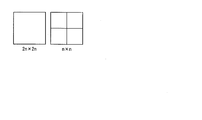
- the CU is a block having the same size as the LCU, or a square block obtained by equally dividing the LCU into four as shown in FIG. 11, or obtained by repeatedly applying this four-division processing to the LCU. It is a square block.
- the size of the LCU is (2 to the power of N) ⁇ (2 to the power of N)
- the size of the CU is (2 to the power of M) ⁇ (2 to the power of M) (3 ⁇ M ⁇ N, where N and M Is an integer).
- PU is a unit for setting the prediction direction in the CU.
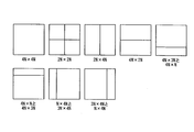
- 12A and 12B are diagrams illustrating examples of PU partition options (PU partition type). As shown in FIG. 12A, in the inter prediction, eight division methods can be selected. Also, as shown in FIG. 12B, in intra prediction, it is possible to select from two division methods only when the CU size is 8 ⁇ 8. Otherwise, PU is identical to CU. In order to improve the coding efficiency, it is necessary to appropriately divide each CU and set the prediction mode of each CU. In particular, as the size of the LCU increases, the degree of freedom in selecting a CU partitioning method and prediction mode increases, and an improvement in coding efficiency is expected by setting an appropriate CU partitioning and prediction mode. Since it is necessary to perform computation for all possible CUs, there is a problem that the amount of computation increases.
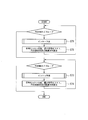
- FIG. 13 is a flowchart showing the processing operation of coding cost calculation for determining the shape of PU division within one CU.
- inter prediction is performed for each PU partition type (step S71). If the coding cost is minimized, the minimum coding cost, the shape of the PU partition that realizes the coding cost, and the inter prediction direction are stored (step S72).
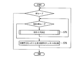
- FIG. 14 is a flowchart showing the processing operation of calculating the coding cost for selecting the CU partition size within one LCU. First, steps S71 to S74 shown in FIG. 13 are repeated in one CU, and the coding cost is calculated for all CUs to determine the CU size (step S75).
- the encoding cost when the CU is divided into four parts is compared with the encoding cost when the CU is not divided into four parts, and the CU division size that is the minimum encoding cost is selected, and the selected division size is stored (Step S76).
- FIG. 14 there is a description of a QP loop which is not described in the above description.
- a quantization parameter QP that determines a quantization step size can be set for each CU.
- the reference software includes a structure for calculating an optimal encoding cost while changing the value of the quantization parameter QP in order to realize this. For this reason, it is described as a QP loop in FIG.
- the process for selecting the optimum mode and the division shape and the division size for obtaining the minimum coding cost is referred to as an encoding optimization process.
- the expressions LCU and CU are used as the concept of the processing unit in HEVC, but more generally the equivalent to the LCU and CU including other encoding techniques are expressed as blocks and sub-blocks, respectively.
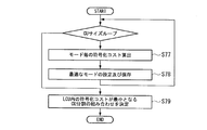
- FIG. 15 is a flowchart showing an encoding optimization processing operation.
- encoding costs for the inter prediction mode, the skip mode, and the intra prediction mode are calculated (step S77).
- an optimum mode is set and stored as a prediction mode of each CU size with the mode that minimizes the coding cost (step S78). This process is repeated for all CU sizes.
- a combination of CU divisions that minimizes the coding cost is determined (step S79).
- the encoding cost means an RD cost represented by the equation (1)
- RD cost D + ⁇ R (1)
- D is the sum of square errors of decoded pixels and original image pixels
- R is the amount of generated code
- ⁇ is a Lagrangian parameter.
- the pseudo RD cost in which D is replaced with the sum of absolute values D ′ of the prediction pixel and the original image pixel and R is replaced with the generated code amount R ′ other than the coefficient code amount
- the coding cost means a cost represented by an RD cost or a pseudo RD cost.
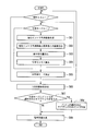
- FIG. 16 is a flowchart illustrating a processing operation for determining an optimal prediction direction for intra prediction. While selecting a certain prediction direction, the processes of steps S82 to S85 described below are repeated (step S81). First, an intra prediction image in the prediction direction is created using neighboring encoded pixels (step S82). Subsequently, an error between the pixel of the intra predicted image and the pixel of the original image is calculated (step S83).
- step S84 the generated code amount is calculated (step S84), and the coding cost is calculated from the error and the generated code amount (step S85). Then, steps S82 to S85 are repeated for each prediction direction. Finally, an optimal intra prediction direction is set by setting the direction in which the calculated coding cost is minimum as the intra prediction direction (step S86).
- a block having a certain size is divided into sub-blocks having an optimum sub-block size, and an optimum prediction mode is determined for each sub-block.
- an optimum prediction mode is determined for each sub-block.
- the encoding of the prediction error is not necessary for the calculation of R ′. Since a prediction image is used for the calculation, it is necessary to encode and decode neighboring pixels used for the calculation. Therefore, when calculating the optimal encoding cost for each sub-block size, the calculation processing is actually reduced only by the arithmetic encoding processing of the prediction error coefficient only by the acceleration using the pseudo RD cost, and the calculation amount It is necessary to perform a decoding process with many sub-block sizes.
- the generated code amount includes both the case where the generated code amount of the coefficient is included and the case where the generated code amount of the coefficient is not included.
- Non-Patent Document 1 As an example of speeding up by a conventional technique.
- Non-Patent Document 1 introduces a method of using pixels of an original image or pixels obtained by applying a filter to pixels of an original image as pixels of a pseudo intra prediction image. With this method, the reference pixels used for calculating the optimal intra prediction mode for each size of the sub-block are only the pixels of the original image or the pixels to which the filter is applied to the pixels of the original image. Can be reduced.
- a pixel of a pseudo intra prediction image is generated using a pixel of an original image or a pixel obtained by applying a fixed filter to a pixel of the original image as a pixel of a reference image for intra prediction.
- the quantization step size, the selected prediction mode, and the like that are considered to affect the original decoded image are not used only by using the pixels of the original image or the pixels obtained by applying the fixed filter to the pixels of the original image. Therefore, there is a problem that correct prediction and cost cannot be calculated.
- the present invention has been made in view of such circumstances, and provides an image encoding method, an image encoding device, and an image encoding program capable of reducing the amount of calculation in intra prediction of encoding optimization processing. For the purpose.
- a reference pixel generation unit that generates a reference pixel from a prediction pixel of a neighboring pixel and a pixel of an original image with respect to an intra prediction direction, and a pseudo intra prediction pixel is generated from the reference pixel and the intra prediction direction
- a pseudo intra prediction pixel generation unit that performs encoding that calculates an encoding cost for the intra prediction direction from an error between the pseudo intra prediction pixel and the pixel of the original image and a generated code amount when generating the pseudo intra prediction pixel It is an image coding apparatus provided with a cost calculation part and an intra prediction direction setting part which sets the intra prediction direction corresponding to the encoding cost which becomes the minimum among the said encoding costs as an optimal intra prediction direction.
- a skip mode determination unit that determines whether or not a prediction mode of a prediction pixel of a neighboring pixel with respect to an intra prediction direction is a skip mode, and a determination result of the skip mode determination unit is the skip mode
- the prediction pixel of the neighboring pixel is used as a reference pixel, an intra prediction pixel is generated from the reference pixel, and when the determination result is a mode other than the skip mode, the prediction pixel of the neighboring pixel and the original image
- An intra prediction pixel / pseudo intra prediction pixel generation unit that generates a reference pixel from the generated pixel and generates a pseudo intra prediction pixel from the generated reference pixel and the intra prediction direction, and the intra prediction pixel or the pseudo intra prediction pixel And pixel error of the original image and the intra prediction pixel or the pseudo intra prediction pixel
- An encoding cost calculation unit that calculates an encoding cost for the intra prediction direction from the generated code amount, and an intra that sets an intra prediction direction corresponding to a minimum encoding cost
- One aspect of the present invention includes a weighting coefficient generation unit that generates a weighting coefficient used when generating a pseudo intra prediction image from a quantization step size of a prediction pixel of a neighboring pixel with respect to an intra prediction direction, and prediction of the neighboring pixel Generating a reference pixel from the pixel and the pixel of the original image using the weighting coefficient, generating a pseudo intra prediction pixel from the reference pixel and the intra prediction direction, and the pseudo intra prediction pixel; An encoding cost calculation unit that calculates an encoding cost for the intra prediction direction from an error of the pixel of the original image and a generated code amount when generating the pseudo intra prediction pixel; and a code that is the smallest of the encoding costs And an intra prediction direction setting unit that sets an intra prediction direction corresponding to the cost of conversion as an optimal intra prediction direction.
- An image encoding device that generates a weighting coefficient used when generating a pseudo intra prediction image from a quantization step size of a prediction pixel of a neighbor
- the encoding cost for the intra prediction direction set in block units by the image encoding method is compared with the encoding cost for a mode other than the intra prediction mode, and the encoding cost for the optimal intra prediction direction is compared.
- intra prediction may be performed again using a neighboring decoded image.
- a reference pixel generation step that generates a reference pixel from a prediction pixel of a neighboring pixel and a pixel of an original image with respect to an intra prediction direction, and a pseudo intra prediction pixel is generated from the reference pixel and the intra prediction direction
- a pseudo-intra prediction pixel generation step and encoding for calculating an encoding cost for the intra-prediction direction from an error between the pseudo-intra prediction pixel and the pixel of the original image and a generated code amount when generating the pseudo-intra prediction pixel
- An image encoding method comprising: a cost calculating step; and an intra prediction direction setting step for setting an intra prediction direction corresponding to a minimum encoding cost among the encoding costs as an optimal intra prediction direction.
- One aspect of the present invention is an image encoding program for causing a computer to execute the image encoding method.
- the amount of encoding calculation can be reduced.
- FIG. 1 is a block diagram showing a configuration of an image encoding apparatus to which the present invention is applied.
- the image coding apparatus 100 includes an intra prediction processing unit 101, an inter prediction processing unit 102, a prediction residual signal generation unit (adding unit) 103, a transform processing unit 104, a quantization processing unit 105, an inverse quantization processing unit 106, and an inverse processing unit.
- a conversion processing unit 107, a decoded signal generation unit (adding unit) 108, a frame memory 109, a deblocking filter processing unit 110, an inter prediction information storage unit 111, an intra prediction information storage unit 112, and an entropy encoding processing unit 113 are provided.
- the configuration of the image encoding device 100 shown in FIG. 1 is equivalent to the HEVC video encoding processing block, and is a known configuration as described in Non-Patent Document 2, Non-Patent Document 3, and the like. Those contents are used as what constitutes a part of this specification, and detailed description thereof is omitted.
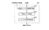
- FIG. 2 is a block diagram showing a detailed configuration of the intra prediction processing unit 101 shown in FIG.
- reference numeral 1011 denotes a pseudo intra prediction image generation unit that generates a pseudo intra prediction image.
- Reference numeral 1012 denotes an encoding cost calculation unit that calculates an encoding cost.
- Reference numeral 1013 denotes an intra prediction direction setting unit that sets an intra prediction direction.
- the intra prediction processing unit 101 uses, as reference pixels for intra prediction, pixels obtained using predicted pixels of neighboring pixels and pixels of the original image instead of decoded pixels.
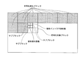
- FIG. 3 shows a case where the sub block in the upper left corner in the encoding target block has already calculated the encoding cost, and the encoding cost of the sub block adjacent to the right is the target of calculation. Show. The sub-block in the upper left corner has already been calculated for the coding cost, but the decoded image is not generated because the block shape has not yet been determined. For this reason, there is no decoded left adjacent pixel used for intra prediction.
- a pseudo-decoded image generated from the reference image (corresponding to the above-mentioned “predicted pixel of the neighboring pixel”) and the original image (“predicted pixel of the neighboring pixel and the original image described later”)
- the pseudo intra prediction image is generated from the pseudo decoded image and the intra prediction direction using the “reference pixel” in the “reference pixel obtained using the pixel”).
- the actual decoded image is generated at a timing after the block division shape of the entire decoding target block is determined (see, for example, FIGS. 6 and 10).
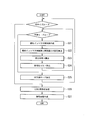
- FIG. 4 is a flowchart showing an intra prediction processing operation using a pseudo decoded image in the intra prediction processing unit 101 shown in FIG.
- the pseudo intra predicted image generation unit 1011 repeats the processes of steps S1 to S4 described below while selecting one intra prediction direction (step S0).
- the pseudo intra prediction image generation unit 1011 generates a pseudo intra prediction pixel from the reference pixel and the intra prediction direction obtained using the prediction pixel of the neighboring pixel and the pixel of the original image (step S1).
- the pseudo intra predicted image generation unit 1011 generates, as the pixel value of the reference pixel, the average value of the pixel values of the original image pixels at the same position as the pixel values of the predicted pixels of the neighboring pixels.
- the pseudo intra predicted image generation unit 1011 calculates an error from the pixel of the original image based on the generated pseudo intra predicted pixel (step S2). Then, the pseudo intra prediction image generation unit 1011 calculates the amount of generated code by the pseudo intra prediction pixel generation (step S3).
- the encoding cost calculation unit 1012 calculates the encoding cost for each intra prediction direction (step S4). After selecting all intra prediction directions, the intra prediction direction setting unit 1013 sets the intra prediction direction that minimizes the coding cost as the optimal intra prediction direction (step S5).
- pseudo intra prediction pixels are generated from reference pixels obtained by using neighboring prediction pixels and original image pixels instead of neighboring decoded pixels, and the cost for each prediction direction of intra prediction is reduced. calculate. This eliminates the need for the decoding process while deriving an appropriate prediction cost, and thus can reduce the amount of computation while suppressing a decrease in encoding efficiency in the encoding optimization process.
- FIG. 5 is a flowchart showing the operation of CU partitioning within 1 LCU and prediction mode determination processing in the conventional processing.
- an intra prediction image in each prediction mode is created using neighboring encoded pixels (step S11).
- an error between the pixel of the intra predicted image and the pixel of the original image is calculated (step S12).
- the generated code amount is calculated (step S13), and the encoding cost is calculated from the error and the generated code amount (step S14).
- Steps S11 to S14 are repeated for all prediction modes.
- the prediction mode that minimizes the coding cost is determined as the prediction mode for each CU size (step S15).
- a decoded image is generated according to the determined prediction mode (step S16). Steps S11 to S16 are repeated for all CU sizes.
- a combination of CU partitions that minimizes the coding cost is obtained, and an LCU partition shape is determined (step S17).
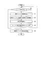
- FIG. 6 is a flowchart showing the operation of CU partitioning within 1 LCU and prediction mode determination processing according to this embodiment.
- a pseudo intra prediction pixel in each prediction mode is generated from the reference pixel obtained using the prediction pixel of the neighboring pixel and the pixel of the original image and the prediction mode (step S21).
- an error between the pixel of the generated pseudo intra prediction image and the pixel of the original image is calculated (step S22).
- the generated code amount is calculated (step S23), and the coding cost is calculated from the error and the generated code amount (step S24). Steps S21 to S24 are repeated for all prediction modes.
- the prediction mode that minimizes the coding cost is determined as the prediction mode for each CU size (step S25).
- Steps S21 to S25 are repeated for all CU sizes.
- a combination of CU divisions that minimizes the coding cost is obtained, and an LCU division shape is determined (step S26).
- a decoded image is generated according to the determined LCU division shape (step S27).
- step S16 of FIG. 6 it is necessary to generate a decoded pixel for each CU size as shown in step S16 of FIG.
- step S27 of FIG. 6 since it is not necessary to use a neighboring decoded pixel in each intra prediction, as shown in step S27 of FIG. 6, the generation of a decoded pixel needs to be performed only once for one LCU. As a result, the calculation amount is reduced.
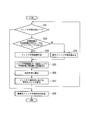
- FIG. 7 is a flowchart showing an intra prediction processing operation using a pseudo decoded image in the intra prediction processing unit 101 shown in FIG.
- a reference pixel is generated using a prediction pixel of a neighboring pixel and a pixel of an original image
- a pixel obtained in consideration of a prediction mode of the prediction pixel of the neighboring pixel is used.
- the pseudo intra predicted image generation unit 1011 repeats the processes of steps S32 to S37 described below while selecting one intra prediction direction (step S31).
- the pseudo intra prediction image generation unit 1011 determines whether or not the prediction mode of the prediction pixel of the neighboring pixels is the skip mode (step S32). As a result of this determination, “when the prediction mode of the prediction pixel of the neighboring pixels is the skip mode”, the pseudo intra prediction image generation unit 1011 generates an intra prediction pixel using the prediction pixel in the skip mode (step S33). .
- the pseudo intra prediction image generation unit 1011 uses the prediction pixel in the skip mode and the pixel in the original image.
- a pseudo intra prediction pixel is generated from the reference pixel obtained by using and the intra prediction direction (step S34).
- the pseudo intra predicted image generation unit 1011 generates, as the pixel value of the reference pixel, the average value of the pixel values of the original image pixels at the same position as the pixel values of the predicted pixels of the neighboring pixels.
- the pseudo intra prediction image generation unit 1011 calculates an error from the pixel of the original image based on the generated intra prediction pixel or pseudo intra prediction pixel (step S35). Then, the pseudo intra predicted image generation unit 1011 calculates a generated code amount by generating an intra prediction pixel or a pseudo intra prediction pixel (step S36).
- the encoding cost calculation unit 1012 calculates the encoding cost for each intra prediction direction (step S37). Then, the intra prediction direction setting unit 1013 sets the intra prediction direction that minimizes the coding cost as the optimal intra prediction direction (step S38).
- the neighboring decoded pixels are not used, but the prediction pixels of the neighboring pixels are switched according to the prediction mode of the neighboring pixels, and the switched pixels are used as the pseudo intra prediction pixels.
- step S33 when the prediction mode of the prediction pixel of the neighboring pixels is the skip mode, since the prediction pixel in the skip mode is a decoded pixel, it is expressed as “intra prediction image” instead of “pseudo intra prediction image”. Yes.
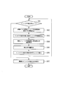
- FIG. 8 is a flowchart showing an intra prediction processing operation using a pseudo decoded image in the intra prediction processing unit 101 shown in FIG.
- the pseudo intra predicted image generation unit 1011 repeats the processes of steps S42 to S46 described below while selecting one intra prediction direction (step S41).
- the pseudo intra prediction image generation unit 1011 determines the weighting coefficient of the pseudo intra prediction pixel from the quantization step size of the neighboring pixels (step S42). For example, when the quantization step size is large, the weighting coefficient is determined by adjusting the weighting coefficient so that the weighting is larger for the predicted pixel of the neighboring pixel than the pixel of the original image. When the quantization step size is small, the weighting coefficient is determined by adjusting the weighting coefficient so that the weighting is larger for the pixels of the original image than the predicted pixels of the neighboring pixels.
- the pseudo intra prediction image generation unit 1011 generates a reference pixel from the prediction pixel of the neighboring pixel and the pixel of the original image by using a weighting coefficient, and performs pseudo prediction for each intra prediction direction from the generated reference pixel and the intra prediction direction. Intra prediction pixels are generated (step S43). Subsequently, the pseudo intra predicted image generation unit 1011 calculates an error from the pixel of the original image based on the generated pseudo intra predicted pixel (step S44). Then, the pseudo intra predicted image generation unit 1011 calculates the generated code amount by the pseudo intra predicted pixel generation (step S45).
- the encoding cost calculation unit 1012 calculates the encoding cost for each intra prediction direction (step S46). Then, the intra prediction direction setting unit 1013 sets the intra prediction direction that minimizes the coding cost as the optimal intra prediction direction (step S47).
- the reference pixel and the intra prediction direction obtained as a weighted sum of the neighboring prediction pixels based on the quantization step size and the pixels of the original image Pseudo intra prediction pixels are derived from and used.
- a decoding process is not necessary while deriving an appropriate encoding cost, so that it is possible to reduce the amount of computation while suppressing a decrease in encoding efficiency in the encoding optimization process.
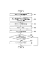
- FIG. 9 is a flowchart showing a processing operation for calculating the correct direction of intra prediction in the intra prediction direction setting unit 1013 shown in FIG.
- the process shown in FIG. 9 uses the pseudo intra prediction pixel calculated by the first to third embodiments and its encoding cost only for prediction mode determination, and when the optimal prediction mode of the sub-block is intra, After the sub-block size is determined, the correct direction of intra prediction is calculated again using the original decoded pixel as a reference pixel.
- the pseudo intra prediction image generation unit 1011 generates a pseudo intra prediction pixel from the reference pixel obtained using the prediction pixel of the neighboring pixel and the pixel of the original image and the intra prediction direction (step S51). Subsequently, the coding cost calculation unit 1012 calculates the coding cost in each intra prediction direction based on the generated pseudo intra prediction pixels (step S52).
- the intra prediction direction setting unit 1013 sets the direction that minimizes the coding cost as the provisional intra prediction direction (step S53).
- the intra prediction direction setting unit 1013 determines the prediction mode by comparing the coding costs for each prediction mode (step S54). And the intra prediction direction setting part 1013 determines the division
- the intra prediction direction setting unit 1013 determines whether or not there is a sub-block for which intra is selected in the prediction mode (step S56). When there is a sub-block for which intra is selected as the prediction mode, the intra-prediction direction setting unit 1013 calculates an actual decoded pixel for only the corresponding sub-block and performs intra-prediction, and the result is the intra-block of the sub-block. The prediction direction is saved (step S57).
- the sub-block size and the optimal prediction mode are determined based on the reference pixel obtained using the neighboring prediction pixel and the original image pixel instead of the neighboring decoded pixel and the intra prediction direction.
- Intra prediction pixels are derived and used. This eliminates the need for a decoding process while deriving an appropriate encoding cost.
- the calculation of the intra prediction direction is performed again only for the subblock for which the intra prediction is optimal. This makes it possible to perform more appropriate intra prediction without increasing unnecessary decoding processing. For this reason, the present embodiment can realize an improvement in encoding efficiency while suppressing an increase in the amount of encoding calculation with respect to the processes of the first to third embodiments.
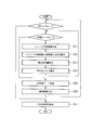
- FIG. 10 is a flowchart illustrating the operation of CU partitioning within 1 LCU and prediction mode determination processing in the fourth embodiment.
- the processes in steps S61 to S66 and S69 are the same as the processes in steps S21 to S27 shown in FIG.
- the optimal prediction mode and the intra prediction result for determining the division shape and the division size are used as they are, when the optimal prediction mode of the sub-block is intra, an appropriate intra prediction direction is selected. It may not be.
- step S67 after determining the division shape of the block, it is determined whether there is a sub-block for which intra is selected in the prediction mode (step S67), and only when the optimal prediction mode is intra, As in step S68 in FIG. 10, the intra prediction direction is obtained again using the decoded pixels. For this reason, in the fourth embodiment, it is possible to perform more appropriate intra prediction while suppressing an increase in the amount of coding calculation compared to the first to third embodiments.
- the input image is divided into 64 ⁇ 64 pixel LCUs (hereinafter, 64 ⁇ 64 LCUs) (processing 1).
- the encoding cost of each prediction mode of the inter prediction mode and the skip mode is calculated for the N ⁇ N size CU in the upper left corner of the upper left LCU using the encoded frame, and the encoding is performed.
- the mode that minimizes the cost and the encoding cost C1 are stored (processing 2).
- a reference pixel is generated according to the prediction mode of the neighboring pixels (processing 3). If the prediction mode of the neighboring pixel is the skip mode, an intra prediction pixel of the encoding target CU is generated by applying a filter according to the direction of intra prediction to the prediction pixel of the neighboring pixel (processing 3-1). On the other hand, when the prediction mode of the neighboring pixel is other than the skip mode, the average value of the prediction pixel of the neighboring pixel and the pixel of the original image at the same position is calculated as a reference pixel, and the pixel value corresponds to the direction of intra prediction. A filter is applied to generate a pseudo intra prediction pixel of the encoding target CU (processing 3-2).
- the process 3 is performed for each intra prediction direction, the encoding cost C2 that is the minimum is compared with the encoding cost C1, and if the encoding cost C2 is small, the intra prediction direction and the encoding cost are stored. If the coding cost C1 is small, the coding cost C1 is stored in the coding cost C2 as it is (processing 4). That is, the loop process is advanced so that the minimum value is stored in the encoding cost C2.
- Processes 2 to 4 are repeated for each CU size 8 ⁇ 8 to 64 ⁇ 64, and the optimal prediction mode and its encoding cost are calculated for all CU sizes in the LCU at the upper left (Process 5).
- the encoding cost of the 16 ⁇ 16 pixel CU (hereinafter referred to as 16 ⁇ 16 CU) in the upper left corner and the encoding cost of the four 8 ⁇ 8 pixel CUs (hereinafter referred to as 8 ⁇ 8 CU) in the inside thereof.
- the sums are compared, and the one with the smaller coding cost is selected as the optimum CU, and the CU partition information, the prediction mode of each CU, and the coding cost are stored (processing 6).
- the process 6 is repeated for each 16 ⁇ 16 CU (process 7).
- the sum of the coding cost of a 64 ⁇ 64 pixel CU (hereinafter referred to as 64 ⁇ 64 CU) and the four 32 ⁇ 32 CU coding costs inside the CU is compared.
- the coding cost of the optimum CU selected in the process 8 is used as the coding cost of 32 ⁇ 32 CU.
- the one with the smaller coding cost is selected as the optimum CU, and the CU partition information, the prediction mode of each CU, and the coding cost are stored (process 10 above).
- processes 2 to 10 are repeated for each LCU (process 11).
- the input image is divided into 64 ⁇ 64 LCUs (process 21).
- the encoding cost of each prediction mode of the inter prediction mode and the skip mode is calculated for the N ⁇ N size CU in the upper left corner of the upper left LCU using the encoded frame, and the encoding is performed.
- the mode with the lowest cost and the encoding cost C1 are stored (process 22).
- a reference pixel is generated according to the prediction mode of the neighboring pixels (processing 23).
- the prediction mode of the neighboring pixel is the skip mode
- an intra prediction pixel of the encoding target CU is generated by applying a filter according to the direction of intra prediction to the prediction pixel of the neighboring pixel (processing 23-1).
- the prediction mode of the neighboring pixel is other than the skip mode
- a weighted sum based on the quantization step size of the neighboring pixel is calculated for the pixel of the original image at the same position as the prediction pixel of the neighboring pixel and used as a reference pixel.
- a filter corresponding to the direction of intra prediction is applied to the pixel value to generate a pseudo intra prediction pixel of the encoding target CU (process 23-2).
- the calculation method of the weighted sum is as follows.
- Process 23 is performed for each intra prediction direction, and the minimum encoding cost C2 and the encoding cost C1 are compared. If the encoding cost C2 is small, the intra prediction direction and the encoding cost are stored, and the encoding is performed. If the cost C1 is small, the encoding cost C1 is stored as it is in the encoding cost C2 (process 24). The processes 22 to 24 are repeated for each CU size 8 ⁇ 8 to 64 ⁇ 64, and the optimal prediction mode and the encoding cost thereof are calculated for the CUs of all sizes in the upper left LCU (process 25).
- the encoding cost of 16 ⁇ 16 CU in the upper left corner is compared with the sum of the encoding costs of four 8 ⁇ 8 CUs in the upper left corner, and the one with the smaller encoding cost is selected as the optimal CU.
- the information, the prediction mode of each CU, and the encoding cost are stored (process 26).
- the process 26 is repeated for each 16 ⁇ 16 CU (process 27).
- the sum of the encoding cost of 32 ⁇ 32 CU in the upper left corner and the encoding costs of the four 16 ⁇ 16 CUs inside it is compared.
- the encoding cost of the optimal CU selected in the process 26 is used as the encoding cost of 16 ⁇ 16 CU.
- the one with the smaller coding cost is selected as the optimum CU, and the CU partition information, the prediction mode of each CU, and the coding cost are stored (step 28). Then, the process 28 is repeated for each 32 ⁇ 32 CU (process 29).
- the sum of the 64 ⁇ 64 CU encoding cost and the four 32 ⁇ 32 CU encoding costs inside it is compared.
- the encoding cost of the optimum CU selected in the process 28 is used as the encoding cost of 32 ⁇ 32 CU.
- the one with the smaller coding cost is selected as the optimum CU, and the CU partition information, the prediction mode of each CU, and the coding cost are stored (processing 30).
- the processes 22 to 30 are repeated for each LCU (process 31).
- the input image is divided into 64 ⁇ 64 LCUs (process 41).
- the encoding cost of each prediction mode of the inter prediction mode and the skip mode is calculated using the encoded frame for the N ⁇ N size CU in the upper left corner in the upper left LCU, and the encoding cost is calculated.
- the encoding cost C1 is stored (process 42).
- reference pixels are generated according to the prediction mode of the neighboring pixels (processing 43). If the prediction mode of the neighboring pixels is the skip mode, an intra prediction pixel of the coding target CU is generated by applying a filter according to the direction of intra prediction to the prediction pixels of the neighboring pixels (processing 43-1). On the other hand, if the prediction mode of the neighboring pixel is other than the skip mode, a weighted sum based on the quantization step size of the neighboring pixel is calculated for the pixel of the original image at the same position as the prediction pixel of the neighboring pixel and used as a reference pixel. Then, a filter corresponding to the direction of intra prediction is applied to the pixel value to generate a pseudo intra prediction pixel of the encoding target CU (processing 43-2).
- the calculation method of the weighted sum is as follows.
- the processing 43 is performed for each intra prediction direction, the encoding cost C2 that is the minimum is compared with the encoding cost C1, and if the encoding cost C2 is small, the intra prediction direction and the encoding cost are stored. If the coding cost C1 is small, the coding cost C1 is stored as it is in the coding cost C2 (process 44).
- the processes 42 to 44 are repeated for each CU size 8 ⁇ 8 to 64 ⁇ 64, and the optimum prediction mode and the encoding cost thereof are calculated for the CUs of all sizes in the upper left LCU (process 45).
- the encoding cost of 16 ⁇ 16 CU in the upper left corner is compared with the sum of the encoding costs of four 8 ⁇ 8 CUs in the upper left corner, and the one with the smaller encoding cost is selected as the optimal CU.
- Information, the prediction mode of each CU, and the coding cost are stored (process 46). Then, the process 46 is repeated for each 16 ⁇ 16 CU (process 47).
- the 32 ⁇ 32 CU encoding cost in the upper left corner is compared with the sum of the four 16 ⁇ 16 CU encoding costs inside.
- the encoding cost of the optimal CU selected in the process 46 is used as the encoding cost of 16 ⁇ 16 CU.
- the one with the smaller coding cost is selected as the optimum CU, and the CU partition information, the prediction mode of each CU, and the coding cost are stored (step 48).
- the process 48 is repeated for each 32 ⁇ 32 CU (process 49).
- the sum of the 64 ⁇ 64 CU encoding cost and the four 32 ⁇ 32 CU encoding costs inside it is compared.
- the encoding cost of the optimum CU selected in the process 48 is used as the encoding cost of 32 ⁇ 32 CU.
- the one with the smaller coding cost is selected as the optimum CU, and the CU partition information, the prediction mode of each CU, and the coding cost are stored (process 50 above).
- the peripheral pixels are sequentially decoded in the fixed CU division size and mode.
- the optimum intra prediction direction is obtained and stored only for the intra prediction location (process 51). Then, the processes 42 to 51 are repeated for each LCU.
- the encoding cost for the pseudo intra prediction image generated from the prediction pixel of the neighboring pixel and the reference pixel obtained using the pixel of the original image and the intra prediction direction instead of the neighboring decoded pixel is calculated, By determining the optimal prediction direction based on the coding cost, it is possible to reduce the amount of calculation required for intra prediction.
- the intra prediction processing unit 101 in the above-described embodiment may be realized by a computer.
- the intra prediction processing unit 101 is realized by recording a program for realizing this function in a computer-readable recording medium, causing the computer system to read and execute the program recorded in the recording medium.
- the “computer system” includes hardware such as an OS (Operating System) and peripheral devices.
- “Computer-readable recording medium” means a portable medium such as a flexible disk, a magneto-optical disk, a ROM (Read Only Memory), a CD (Compact Disk) -ROM, or a hard disk built in a computer system. Refers to the device.
- the “computer-readable recording medium” dynamically holds a program for a short time like a communication line when transmitting a program via a network such as the Internet or a communication line such as a telephone line.
- a volatile memory inside a computer system serving as a server or a client in that case may be included and a program held for a certain period of time.
- the program may be a program for realizing a part of the functions described above, and may be a program capable of realizing the functions described above in combination with a program already recorded in a computer system.
- the intra prediction processing unit 101 may be realized by using hardware such as PLD (Programmable Logic Device) and FPGA (Field Programmable Gate Array).
- the present invention calculates a coding cost for a pseudo intra prediction image generated from a reference pixel and an intra prediction direction obtained using a prediction pixel of a neighboring pixel and a pixel of an original image instead of a neighboring decoded pixel, and the encoding By determining the optimal prediction direction based on the cost, the present invention can be applied to a use for reducing the amount of calculation required for intra prediction.
- Intra prediction processing unit 1011 ... Pseudo intra prediction image generation unit, 1012 ... Coding cost calculation unit, 1013 ... Intra prediction direction setting unit
Landscapes
- Engineering & Computer Science (AREA)
- Multimedia (AREA)
- Signal Processing (AREA)
- Computing Systems (AREA)
- Theoretical Computer Science (AREA)
- Compression Or Coding Systems Of Tv Signals (AREA)
Abstract
符号化最適化処理のイントラ予測における演算量を削減することができる画像符号化装置を提供する。画像符号化装置は、イントラ予測方向に対して近傍画素の予測画素と原画像の画素から参照画素を生成する参照画素生成部と、参照画素とイントラ予測方向から疑似イントラ予測画素を生成する疑似イントラ予測画素生成部と、疑似イントラ予測画素と原画像の画素の誤差と疑似イントラ予測画素を生成する際の発生符号量からイントラ予測方向に対する符号化コストを算出する符号化コスト算出部と、符号化コストのうち最小となる符号化コストに対応するイントラ予測方向を最適なイントラ予測方向として設定するイントラ予測方向設定部とを備える。
Description
本発明は、画像符号化方法、画像符号化装置及び画像符号化プログラムに関する。
本願は、2013年7月25日に日本へ出願された特願2013-155034号に基づき優先権を主張し、その内容をここに援用する。
本願は、2013年7月25日に日本へ出願された特願2013-155034号に基づき優先権を主張し、その内容をここに援用する。
従来技術である規格H.264の次の映像符号化標準方式として策定されたHEVC(High Efficiency Video Coding)は、規格H.264を上回る符号化効率を実現する符号化方式である。しかし、HEVCは、処理が複雑であって演算量が莫大であるため、実際にHEVCを製品に利用するためにはその符号化演算コストを大幅に削減しなければならない、という問題を抱えている。特に、HEVCでは、符号化を行う単位であるブロックのサイズの選択肢が増加したため、最適なブロックサイズやモードの決定を行う符号化最適化に伴う処理が増大しており、この演算量を削減することが必要となっている。
映像符号化の際には、一般に画素をブロック単位で符号化している。HEVCではその符号化を行うブロックとしてLCU(Largest Coding Unit)及びCU(Coding Unit)という概念を導入し、また、予測の単位にPU(Prediction Unit)という概念を導入している。以下、LCU、CU及びPUについて説明する。HEVCでは、1枚のピクチャ(画像)は、図11に示すように一定サイズの正方形に均等に分割される。図11は、ピクチャの分割例を示す図である。図11に示す正方形ブロックをLCUと呼ぶ。LCUのサイズは、16×16画素、32×32画素、64×64画素から選択可能であるが、1枚のピクチャ内では全て同一である。
実際の符号化を行う単位であるCUは、ある一つのLCU内に存在する正方形ブロックであり、CUを単位として予測モードが決定される。CUは、LCUと同一サイズのブロック、あるいは、図11に示すように、LCUを均等に4分割して得られる正方形のブロック、または、この4分割処理をLCUに対して繰り返し適用して得られる正方形のブロックである。CUのサイズは、LCUのサイズが(2のN乗)×(2のN乗)であるとき、(2のM乗)×(2のM乗)(3≦M≦N、但しN及びMは整数)から選択可能である。
また、PUは、CU内の予測方向を設定するための単位である。図12A及び図12Bは、PU分割の選択肢(PU分割タイプ)の例を示す図である。図12Aに示すように、インター予測では8通りの分割方法から選択可能である。また、図12Bに示すように、イントラ予測ではCUサイズが8×8のときのみ2通りの分割方法から選択可能である。それ以外の場合は、PUはCUと同一である。符号化効率向上のためには、各LCUに対し適切なCU分割及び各CUの予測モード設定が必要となる。特にLCUのサイズが大きくなるほど、CUの分割方法及び予測モードの選択の自由度が増加し、適切なCU分割及び予測モードの設定を行うことで符号化効率の向上が期待される一方、選択肢となりうる全てのCUについて演算を行う必要があるため、その演算量が増加するという問題がある。
実際の1LCUにおけるCUサイズの選択に関する処理について、HEVCテストモデル(HM)を例にして説明する。初めに図13を参照して、1CU内でのPU分割の形状決定のための符号化コスト計算の処理動作について説明する。図13は、1CU内でのPU分割の形状決定のための符号化コスト計算の処理動作を示すフローチャートである。まず、各PU分割タイプについて、インター予測を行う(ステップS71)。そして、符号化コストが最小となる場合、最小符号化コスト、ならびに、それを実現するPU分割の形状及びインター予測方向を保存する(ステップS72)。
次に、各PU分割タイプのそれぞれについて、イントラ予測を行う(ステップS73)。そして、符号化コストが最小となる場合、最小符号化コスト、ならびに、それを実現するPU分割の形状、及びイントラ予測方向を保存する(ステップS74)。
次に、図14を参照して、1LCU内でのCU分割サイズ決定のための符号化コスト計算の処理動作について説明する。図14は、1LCU内でのCU分割サイズ選択のための符号化コスト計算の処理動作を示すフローチャートである。まず、1CU内において図13に示すステップS71~S74を繰り返し、すべてのサイズのCUについて、符号化コストを計算してCUサイズを決定する(ステップS75)。LCUについて、CUを4分割した場合の符号化コストとCUを4分割しない場合の符号化コストを比較して最小符号化コストとなるCUの分割サイズを選択し、選択された分割サイズを保存する(ステップS76)。
次に、図14を参照して、1LCU内でのCU分割サイズ決定のための符号化コスト計算の処理動作について説明する。図14は、1LCU内でのCU分割サイズ選択のための符号化コスト計算の処理動作を示すフローチャートである。まず、1CU内において図13に示すステップS71~S74を繰り返し、すべてのサイズのCUについて、符号化コストを計算してCUサイズを決定する(ステップS75)。LCUについて、CUを4分割した場合の符号化コストとCUを4分割しない場合の符号化コストを比較して最小符号化コストとなるCUの分割サイズを選択し、選択された分割サイズを保存する(ステップS76)。
なお、図14には前述の説明では説明していないQPループなる記載がある。HEVCでは、固定の量子化パラメータQPによるエンコードでない場合は、CUごとに、量子化ステップサイズを定める量子化パラメータQPを設定することが可能となっている。参照ソフトウェアには、それを実現するために量子化パラメータQPの値を変更しながら最適な符号化コストを算出する構造が入っている。このため、図14ではQPループと記載したものである。
最小符号化コストを得るため最適なモードならびに分割形状および分割サイズを選択するための処理を、符号化最適化処理と呼ぶ。なお、以下ではHEVCにおける処理単位の概念としてLCU、CUという表現を用いるが、その他の符号化技術を含め、より一般的にLCU、CUに相当するものを、それぞれブロック、サブブロックとして表現する。
次に、符号化最適化の処理動作を説明する。図15は、符号化最適化の処理動作を示すフローチャートである。まず、インター予測モード、スキップモード、及び、イントラ予測モードの符号化コストを算出する(ステップS77)。続いて、符号化コストが最小となるモードを各CUサイズの予測モードとして最適なモードの設定及び保存を行う(ステップS78)。この処理はすべてのCUサイズについて繰り返す。そして、符号化コストが最小となるCU分割の組み合わせを決定する(ステップS79)。
ここで、符号化コストとは、(1)式に代表されるようなRDコストを意味し、最適化とは符号化コストが最小となるような符号化を決定することを意味する。
RDコスト=D+λR ・・・(1)
(1)式において、Dは復号画素と原画像の画素の二乗誤差和、Rは発生符号量、λはラグランジアンパラメータである。また、符号化最適化処理の高速化のために、Dを予測画素と原画像の画素の絶対値和D’と置き換え、Rを係数符号量以外の発生符号量R’と置き換えた疑似RDコストを符号化コストとする手法も存在する。これ以降、符号化コストとはRDコストまたは疑似RDコストに代表されるようなコストを意味するものとする。
RDコスト=D+λR ・・・(1)
(1)式において、Dは復号画素と原画像の画素の二乗誤差和、Rは発生符号量、λはラグランジアンパラメータである。また、符号化最適化処理の高速化のために、Dを予測画素と原画像の画素の絶対値和D’と置き換え、Rを係数符号量以外の発生符号量R’と置き換えた疑似RDコストを符号化コストとする手法も存在する。これ以降、符号化コストとはRDコストまたは疑似RDコストに代表されるようなコストを意味するものとする。
次に、図16を参照して、イントラ予測の最適な予測方向を決定するための処理動作を説明する。図16は、イントラ予測の最適な予測方向を決定するための処理動作を示すフローチャートである。ある予測方向を選択しながら繰り返し以下に述べるステップS82~S85の処理を行う(ステップS81)。まず、近傍の符号化済み画素を用いて、予測方向におけるイントラ予測画像を作成する(ステップS82)。続いて、イントラ予測画像の画素と原画像の画素との誤差を算出する(ステップS83)。
次に、発生符号量を算出し(ステップS84)、誤差と発生符号量から符号化コストを算出する(ステップS85)。そして、ステップS82~S85を各予測方向について繰り返す。最後に、算出した符号化コストが最小となる方向をイントラ予測方向とすることにより、最適なイントラ予測方向の設定を行う(ステップS86)。
符号化最適化処理においては、ある一定サイズのブロックに対し、そのブロックを最適なサブブロックサイズのサブブロックに分割して、サブブロックごとに最適な予測モードを決定している。ブロック単位で上記の最適なサブブロックサイズ及び予測モードを決定するため、前述したように、サブブロックサイズごとに各予測モードにおける符号化コストを求める必要がある。特に最適なイントラ予測方向の決定には、各イントラ予測方向に対する予測画像作成に必要な近傍の符号化済み画素の復号が必要である。これらの処理は、最適なサイズではないサブブロックに対しても行われるが、その場合には、近傍画素の復号結果は上記符号化コストの比較以外に用いられることはない。
特に、符号化最適化処理の高速化を目的とする手法の一つである疑似RDコストを用いた判定の場合、R’の計算には予測誤差の符号化が不要であるが、D’の計算には予測画像を用いるため、その算出に用いる近傍画素について符号化及び復号が必要である。そのため、各サブブロックサイズの最適な符号化コストを求める際、疑似RDコストを用いた高速化のみでは、実際に演算処理が削減されるのは予測誤差係数の算術符号化処理のみとなり、演算量が多い復号処理については、各サブブロックサイズに対して行う必要が発生する。
なお、以下で発生符号量と記す場合は、係数の発生符号量を含む場合、係数の発生符号量を含まない場合のどちらの場合も含むものとする。
なお、以下で発生符号量と記す場合は、係数の発生符号量を含む場合、係数の発生符号量を含まない場合のどちらの場合も含むものとする。
従来技術による高速化を行う例として非特許文献1がある。非特許文献1では、原画像の画素、または原画像の画素にフィルタを適用した画素を疑似イントラ予測画像の画素として用いる手法が紹介されている。この手法により、サブブロックの各サイズの最適イントラ予測モードの算出に用いる参照画素は原画像の画素あるいは原画像の画素にフィルタを適用した画素のみとなるため、近傍画素の復号が不要となり演算量を削減できる。
Takafumi Bando, Naoyuki Hirai, Tian Song, and Takashi Shimamoto, "New Prediction Modes for Parallel Processing of H.264/AVC", Proceedings of International Conference on Multimedia and Signal Processing (CMSP'11), pp. 344-347, Guilin, China, May 2011.
大久保 榮,鈴木 輝彦,高村 誠之,中條 健,"インプレス標準教科書シリーズH.265/HEVC教科書",インプレスジャパン,2013/10/18
K. McCann, B. Bross, W.-J. Han, I. K. Kim, K. Sugimoto, G. J. Sullivan, "High Efficiency Video Coding (HEVC) Test Model 15 (HM 15) Encoder Description", Joint Collaborative Team on Video Coding (JCT-VC) document JCTVC-Q1002, Mar. 2014.
非特許文献1の手法では、イントラ予測の参照画像の画素に、原画像の画素または原画像の画素に固定フィルタを適用した画素を用いて疑似イントラ予測画像の画素を生成している。
しかしながら、原画像の画素のみ、または原画像の画素に固定フィルタを適用した画素を用いるのみでは、本来の復号画像に影響を与えると考えられる量子化ステップサイズや選択された予測モードなどが使用されないため、正しい予測やコストの算出ができないという問題がある。
本発明は、このような事情に鑑みてなされたもので、符号化最適化処理のイントラ予測における演算量を削減することができる画像符号化方法、画像符号化装置及び画像符号化プログラムを提供することを目的とする。
本発明の一態様は、イントラ予測方向に対して近傍画素の予測画素と原画像の画素から参照画素を生成する参照画素生成部と、前記参照画素と前記イントラ予測方向から疑似イントラ予測画素を生成する疑似イントラ予測画素生成部と、前記疑似イントラ予測画素と前記原画像の画素の誤差と前記疑似イントラ予測画素を生成する際の発生符号量から前記イントラ予測方向に対する符号化コストを算出する符号化コスト算出部と、前記符号化コストのうち最小となる符号化コストに対応するイントラ予測方向を最適なイントラ予測方向として設定するイントラ予測方向設定部とを備える画像符号化装置である。
本発明の一態様は、イントラ予測方向に対する近傍画素の予測画素の予測モードがスキップモードであるか否か判定するスキップモード判定部と、前記スキップモード判定部の判定結果が前記スキップモードである場合には、前記近傍画素の予測画素を参照画素とし、前記参照画素からイントラ予測画素を生成し、前記判定結果が前記スキップモード以外のモードである場合には、前記近傍画素の予測画素と原画像の画素から参照画素を生成し、生成された前記参照画素と前記イントラ予測方向から疑似イントラ予測画素を生成するイントラ予測画素・疑似イントラ予測画素生成部と、前記イントラ予測画素または前記疑似イントラ予測画素と前記原画像の画素の誤差と前記イントラ予測画素または前記疑似イントラ予測画素を生成する際の発生符号量から前記イントラ予測方向に対する符号化コストを算出する符号化コスト算出部と、前記符号化コストのうち最小となる符号化コストに対応するイントラ予測方向を最適なイントラ予測方向として設定するイントラ予測方向設定部とを備える画像符号化装置である。
本発明の一態様は、イントラ予測方向に対する近傍画素の予測画素の量子化ステップサイズから疑似イントラ予測画像を生成する際に用いる重みづけ係数を生成する重みづけ係数生成部と、前記近傍画素の予測画素と原画像の画素から前記重みづけ係数を用いて参照画素を生成し、前記参照画素と前記イントラ予測方向から疑似イントラ予測画素を生成する疑似イントラ予測画素生成部と、前記疑似イントラ予測画素と前記原画像の画素の誤差と前記疑似イントラ予測画素を生成する際の発生符号量から前記イントラ予測方向に対する符号化コストを算出する符号化コスト算出部と、前記符号化コストのうち最小となる符号化コストに対応するイントラ予測方向を最適なイントラ予測方向として設定するイントラ予測方向設定部とを備える画像符号化装置である。
上記画像符号化装置において、前記画像符号化方法によりブロック単位で設定したイントラ予測方向に対する符号化コストとイントラ予測モード以外のモードに対する符号化コストを比較し、前記最適なイントラ予測方向に対する符号化コストの方が小さいブロックについては、近傍の復号画像を用いてイントラ予測をやり直すようにしてもよい。
本発明の一態様は、イントラ予測方向に対して近傍画素の予測画素と原画像の画素から参照画素を生成する参照画素生成ステップと、前記参照画素と前記イントラ予測方向から疑似イントラ予測画素を生成する疑似イントラ予測画素生成ステップと、前記疑似イントラ予測画素と前記原画像の画素の誤差と前記疑似イントラ予測画素を生成する際の発生符号量から前記イントラ予測方向に対する符号化コストを算出する符号化コスト算出ステップと、前記符号化コストのうち最小となる符号化コストに対応するイントラ予測方向を最適なイントラ予測方向として設定するイントラ予測方向設定ステップとを有する画像符号化方法である。
本発明の一態様は、前記画像符号化方法をコンピュータに実行させるための画像符号化プログラムである。
本発明によれば、符号化演算量を削減することができる。特に、本発明によれば、符号化最適化処理のイントラ予測における演算量を削減することができるという効果が得られる。
以下、図面を参照して、本発明を適用する画像符号化装置を説明する。図1は本発明を適用する画像符号化装置の構成を示すブロック図である。画像符号化装置100は、イントラ予測処理部101、インター予測処理部102、予測残差信号生成部(加算部)103、変換処理部104、量子化処理部105、逆量子化処理部106、逆変換処理部107、復号信号生成部(加算部)108、フレームメモリ109、デブロッキングフィルタ処理部110、インター予測情報格納部111、イントラ予測情報格納部112及びエントロピー符号化処理部113を備えている。図1に示す画像符号化装置100の構成は、HEVCの映像符号化処理ブロックと同等であり、非特許文献2や非特許文献3などに記載があるように公知の構成であるため、ここに本明細書の一部を構成するものとしてそれらの内容を援用し、詳細な説明を省略する。
次に、図2を参照して、図1に示すイントラ予測処理部101の詳細な構成を説明する。図2は、図1に示すイントラ予測処理部101の詳細な構成を示すブロック図である。図2において、符号1011は、疑似イントラ予測画像を生成する疑似イントラ予測画像生成部である。符号1012は、符号化コストを算出する符号化コスト算出部である。符号1013は、イントラ予測方向を設定するイントラ予測方向設定部である。イントラ予測処理部101は、イントラ予測の参照画素に、復号済み画素の代わりに近傍画素の予測画素と原画像の画素を用いて求めた画素を用いる。
ここで、図3を参照して、疑似イントラ予測画像及び疑似復号画像について説明する。図3は、符号化対象ブロック内の左上隅にあるサブブロックが既に符号化コストを計算済みであり、かつ、その右隣にあるサブブロックの符号化コストが計算の対象となっている場合を示している。左上隅にあるサブブロックは符号化コストを計算済みであるが、ブロック形状が確定していないため、復号画像は生成されていない状態である。このため、イントラ予測に用いる復号済みの左隣接画素が存在しない。そこで、復号済みの左隣接画素の代わりに、参照画像(上述した「近傍画素の予測画素」に相当)と原画像から生成される疑似復号画像(後述する「近傍画素の予測画素と原画像の画素を用いて求めた参照画素」における「参照画素」に相当)を用い、疑似復号画像とイントラ予測方向から疑似イントラ予測画像を生成する。なお、実際の復号画像は、復号対象ブロック全体のブロック分割形状が決定された以降のタイミングで生成される(例えば、図6及び図10を参照)。
<第1実施形態>
次に、図4を参照して、本発明の第1実施形態による疑似復号画像を用いたイントラ予測の処理動作を説明する。図4は、図2に示すイントラ予測処理部101における疑似復号画像を用いたイントラ予測の処理動作を示すフローチャートである。疑似イントラ予測画像生成部1011は、1つのイントラ予測方向を選択しながら、以下に述べるステップS1~S4の処理を繰り返す(ステップS0)。まず、疑似イントラ予測画像生成部1011は、疑似イントラ予測画素を、近傍画素の予測画素と原画像の画素を用いて求めた参照画素とイントラ予測方向から生成する(ステップS1)。例えば、疑似イントラ予測画像生成部1011は、近傍画素の予測画素の画素値と同一位置にある原画像の画素の画素値との平均値を参照画素の画素値として生成する。
次に、図4を参照して、本発明の第1実施形態による疑似復号画像を用いたイントラ予測の処理動作を説明する。図4は、図2に示すイントラ予測処理部101における疑似復号画像を用いたイントラ予測の処理動作を示すフローチャートである。疑似イントラ予測画像生成部1011は、1つのイントラ予測方向を選択しながら、以下に述べるステップS1~S4の処理を繰り返す(ステップS0)。まず、疑似イントラ予測画像生成部1011は、疑似イントラ予測画素を、近傍画素の予測画素と原画像の画素を用いて求めた参照画素とイントラ予測方向から生成する(ステップS1)。例えば、疑似イントラ予測画像生成部1011は、近傍画素の予測画素の画素値と同一位置にある原画像の画素の画素値との平均値を参照画素の画素値として生成する。
次に、疑似イントラ予測画像生成部1011は、生成された疑似イントラ予測画素をもとに原画像の画素との誤差を算出する(ステップS2)。そして、疑似イントラ予測画像生成部1011は、疑似イントラ予測画素生成による発生符号量を算出する(ステップS3)。
次に、符号化コスト算出部1012は、各イントラ予測方向に対する符号化コストを算出する(ステップS4)。そして、すべてのイントラ予測方向を選択した後、イントラ予測方向設定部1013は、符号化コストが最小となるイントラ予測方向を最適なイントラ予測方向として設定する(ステップS5)。
符号化最適化処理の高速化時のイントラ予測では、符号化コスト算出に復号済み画素を用いるため、適切なサブブロックサイズ及び予測モードを決めるに当たり近傍画素の復号を逐次行う必要がある。これに対して、本実施形態では近傍の復号画素の代わりに近傍の予測画素と原画像の画素を用いて求めた参照画素から疑似イントラ予測画素を生成してイントラ予測の予測方向毎のコストを算出する。これにより、適切な予測コストを導出しつつ上記復号処理が不要となるため、符号化最適化処理における符号化効率の低下を抑制しつつ演算量削減を実現できる。
次に、図5及び図6を参照して、第1実施形態による演算削減対象について説明する。
図5は、従来処理における1LCU内のCU分割及び予測モードの決定処理の動作を示すフローチャートである。まず、近傍の符号化済み画素を用いて、各予測モードにおけるイントラ予測画像を作成する(ステップS11)。次に、イントラ予測画像の画素と原画像の画素との誤差を算出する(ステップS12)。次に、発生符号量を算出し(ステップS13)、誤差と発生符号量から符号化コストを算出する(ステップS14)。すべての予測モードについてステップS11~S14を繰り返す。次に、符号化コストが最小となる予測モードを各CUサイズの予測モードに決定する(ステップS15)。次いで、決定された予測モードにしたがって、復号画像を生成する(ステップS16)。すべてのCUサイズについてステップS11~S16を繰り返す。最後に、符号化コストが最小となるCU分割の組み合わせを求めて、LCU分割形状を決定する(ステップS17)。
図6は、本実施形態による1LCU内のCU分割及び予測モードの決定処理の動作を示すフローチャートである。まず、近傍画素の予測画素と原画像の画素を用いて求めた参照画素と予測モードから各予測モードにおける疑似イントラ予測画素を生成する(ステップS21)。次に、生成された疑似イントラ予測画像の画素と原画像の画素との誤差を算出する(ステップS22)。次に、発生符号量を算出し(ステップS23)、誤差と発生符号量から符号化コストを算出する(ステップS24)。すべての予測モードについてステップS21~S24を繰り返す。次に、符号化コストが最小となる予測モードを各CUサイズの予測モードに決定する(ステップS25)。すべてのCUサイズについてステップS21~S25を繰り返す。次いで、符号化コストが最小となるCU分割の組み合わせを求めて、LCU分割形状を決定する(ステップS26)。最後に、決定されたLCU分割形状にしたがって復号画像を生成する(ステップS27)。
従来処理では、図5のステップS16に示すように、CUサイズごとに復号画素を生成する必要がある。一方、本実施形態では、各イントラ予測において近傍の復号画素を用いなくてよいことから、図6のステップS27に示すように復号画素の生成は1LCUに対して一度のみ行えばよいこととなる。これにより演算量が削減されることとなる。
<第2実施形態>
次に、図7を参照して、本発明の第2実施形態による疑似復号画像を用いたイントラ予測の処理動作を説明する。図7は、図2に示すイントラ予測処理部101における疑似復号画像を用いたイントラ予測の処理動作を示すフローチャートである。図7に示す処理において、近傍画素の予測画素と原画像の画素を用いて参照画素を生成する際に近傍画素の予測画素の予測モードを考慮して求めた画素を用いる。疑似イントラ予測画像生成部1011は、1つのイントラ予測方向を選択しながら、以下に述べるステップS32~S37の処理を繰り返す(ステップS31)。まず、疑似イントラ予測画像生成部1011は、近傍画素の予測画素の予測モードが、スキップモードであるか否かの判定を行う(ステップS32)。この判定の結果、『近傍画素の予測画素の予測モードがスキップモードである場合』、疑似イントラ予測画像生成部1011は、スキップモードの予測画素を用いて、イントラ予測画素を生成する(ステップS33)。
次に、図7を参照して、本発明の第2実施形態による疑似復号画像を用いたイントラ予測の処理動作を説明する。図7は、図2に示すイントラ予測処理部101における疑似復号画像を用いたイントラ予測の処理動作を示すフローチャートである。図7に示す処理において、近傍画素の予測画素と原画像の画素を用いて参照画素を生成する際に近傍画素の予測画素の予測モードを考慮して求めた画素を用いる。疑似イントラ予測画像生成部1011は、1つのイントラ予測方向を選択しながら、以下に述べるステップS32~S37の処理を繰り返す(ステップS31)。まず、疑似イントラ予測画像生成部1011は、近傍画素の予測画素の予測モードが、スキップモードであるか否かの判定を行う(ステップS32)。この判定の結果、『近傍画素の予測画素の予測モードがスキップモードである場合』、疑似イントラ予測画像生成部1011は、スキップモードの予測画素を用いて、イントラ予測画素を生成する(ステップS33)。
一方、『近傍画素の予測画素の予測モードがスキップモード以外のモード(イントラ予測モードまたはインター予測モード)である場合』、疑似イントラ予測画像生成部1011は、スキップモードの予測画素と原画像の画素を用いて求めた参照画素とイントラ予測方向から疑似イントラ予測画素を生成する(ステップS34)。例えば、疑似イントラ予測画像生成部1011は、近傍画素の予測画素の画素値と同一位置にある原画像の画素の画素値との平均値を参照画素の画素値として生成する。
次に、疑似イントラ予測画像生成部1011は、生成されたイントラ予測画素または疑似イントラ予測画素をもとに原画像の画素との誤差を算出する(ステップS35)。そして、疑似イントラ予測画像生成部1011は、イントラ予測画素または疑似イントラ予測画素生成による発生符号量を算出する(ステップS36)。
次に、符号化コスト算出部1012は、各イントラ予測方向に対する符号化コストを算出する(ステップS37)。そして、イントラ予測方向設定部1013は、符号化コストが最小となるイントラ予測方向を最適なイントラ予測方向として設定する(ステップS38)。
符号化最適化処理の高速化時のイントラ予測では、符号化コスト算出に復号済み画素を用いるため、適切なサブブロックサイズ及び予測モードを決めるに当たり近傍画素の復号を逐次行う必要がある。これに対して、本実施形態では、近傍の復号画素を用いるのではなく、近傍画素の予測画素を近傍画素の予測モードに応じて切り替え、切り替えられた画素を疑似イントラ予測画素として用いる。これにより、適切な予測コストを導出しつつ復号処理が不要となるため、符号化最適化処理における符号化効率の低下を抑制しつつ演算量削減を実現できる。
なお、ステップS33(近傍画素の予測画素の予測モードがスキップモードの場合)では、スキップモードの予測画素が復号画素であるため、「疑似イントラ予測画像」ではなく「イントラ予測画像」と表記している。
<第3実施形態>
次に、図8を参照して、本発明の第3実施形態による疑似復号画像を用いたイントラ予測の処理動作を説明する。図8は、図2に示すイントラ予測処理部101における疑似復号画像を用いたイントラ予測の処理動作を示すフローチャートである。図8に示す処理において、近傍画素の予測画素と原画像の画素を用いる際に近傍画素の量子化ステップサイズを考慮して求めた画素を用いる。疑似イントラ予測画像生成部1011は、1つのイントラ予測方向を選択しながら、以下に述べるステップS42~S46の処理を繰り返す(ステップS41)。まず、疑似イントラ予測画像生成部1011は、近傍画素の量子化ステップサイズから疑似イントラ予測画素の重みづけ係数を決定する(ステップS42)。例えば、量子化ステップサイズが大きい場合は原画像の画素よりも近傍画素の予測画素に対して重みづけが大きくなるように重みづけ係数を調整することで重みづけ係数を決定する。また、量子化ステップサイズが小さい場合は近傍画素の予測画素よりも原画像の画素に対して重みづけが大きくなるように重みづけ係数を調整することで重みづけ係数を決定する。
次に、図8を参照して、本発明の第3実施形態による疑似復号画像を用いたイントラ予測の処理動作を説明する。図8は、図2に示すイントラ予測処理部101における疑似復号画像を用いたイントラ予測の処理動作を示すフローチャートである。図8に示す処理において、近傍画素の予測画素と原画像の画素を用いる際に近傍画素の量子化ステップサイズを考慮して求めた画素を用いる。疑似イントラ予測画像生成部1011は、1つのイントラ予測方向を選択しながら、以下に述べるステップS42~S46の処理を繰り返す(ステップS41)。まず、疑似イントラ予測画像生成部1011は、近傍画素の量子化ステップサイズから疑似イントラ予測画素の重みづけ係数を決定する(ステップS42)。例えば、量子化ステップサイズが大きい場合は原画像の画素よりも近傍画素の予測画素に対して重みづけが大きくなるように重みづけ係数を調整することで重みづけ係数を決定する。また、量子化ステップサイズが小さい場合は近傍画素の予測画素よりも原画像の画素に対して重みづけが大きくなるように重みづけ係数を調整することで重みづけ係数を決定する。
次に、疑似イントラ予測画像生成部1011は、近傍画素の予測画素と原画像の画素から重みづけ係数により参照画素を生成し、生成された参照画素とイントラ予測方向から、イントラ予測方向毎に疑似イントラ予測画素を生成する(ステップS43)。続いて、疑似イントラ予測画像生成部1011は、生成された疑似イントラ予測画素をもとに原画像の画素との誤差を算出する(ステップS44)。そして、疑似イントラ予測画像生成部1011は、疑似イントラ予測画素生成による発生符号量を算出する(ステップS45)。
次に、符号化コスト算出部1012は、各イントラ予測方向に対する符号化コストを算出する(ステップS46)。そして、イントラ予測方向設定部1013は、符号化コストが最小となるイントラ予測方向を最適なイントラ予測方向として設定する(ステップS47)。
符号化最適化処理の高速化時のイントラ予測では、符号化コスト算出に復号済み画素を用いるため、適切なサブブロックサイズ及び予測モードを決めるに当たり近傍画素の復号を逐次行う必要がある。これに対して、本実施形態では、近傍の復号画素の代わりに、その量子化ステップサイズをもとにした近傍の予測画素と原画像の画素の重みづけ和として求めた参照画素とイントラ予測方向から疑似イントラ予測画素を導出して用いる。これにより、適切な符号化コストを導出しつつ、復号処理が不要となるため、符号化最適化処理における符号化効率の低下を抑制しつつ演算量削減を実現できる。
<第4実施形態>
次に、図9を参照して、本発明の第4実施形態によるイントラ予測の正しい方向を算出する処理動作を説明する。図9は、図2に示すイントラ予測方向設定部1013におけるイントラ予測の正しい方向を算出する処理動作を示すフローチャートである。図9に示す処理は、第1~第3実施形態により算出される疑似イントラ予測画素とその符号化コストを予測モード判定にのみ用い、そのサブブロックの最適な予測モードがイントラの場合には、サブブロックサイズ確定後に再度本来の復号画素を参照画素としてイントラ予測の正しい方向を算出する。まず、疑似イントラ予測画像生成部1011は、疑似イントラ予測画素を、近傍画素の予測画素と原画像の画素を用いて求めた参照画素とイントラ予測方向から生成する(ステップS51)。続いて、符号化コスト算出部1012は、生成された疑似イントラ予測画素をもとに各イントラ予測方向における符号化コストを算出する(ステップS52)。
次に、図9を参照して、本発明の第4実施形態によるイントラ予測の正しい方向を算出する処理動作を説明する。図9は、図2に示すイントラ予測方向設定部1013におけるイントラ予測の正しい方向を算出する処理動作を示すフローチャートである。図9に示す処理は、第1~第3実施形態により算出される疑似イントラ予測画素とその符号化コストを予測モード判定にのみ用い、そのサブブロックの最適な予測モードがイントラの場合には、サブブロックサイズ確定後に再度本来の復号画素を参照画素としてイントラ予測の正しい方向を算出する。まず、疑似イントラ予測画像生成部1011は、疑似イントラ予測画素を、近傍画素の予測画素と原画像の画素を用いて求めた参照画素とイントラ予測方向から生成する(ステップS51)。続いて、符号化コスト算出部1012は、生成された疑似イントラ予測画素をもとに各イントラ予測方向における符号化コストを算出する(ステップS52)。
次に、イントラ予測方向設定部1013は、符号化コストが最小となる方向を、仮のイントラ予測方向として設定する(ステップS53)。イントラ予測方向設定部1013は、各予測モードに対する符号化コストの比較を行って、予測モードを決定する(ステップS54)。そして、イントラ予測方向設定部1013は、ブロックの分割形状を決定する(ステップS55)。
次に、イントラ予測方向設定部1013は、予測モードにイントラが選択されたサブブロックがあるか否かを判定する(ステップS56)。予測モードとしてイントラが選択されたサブブロックがある場合、イントラ予測方向設定部1013は、該当するサブブロックのみについて、実際の復号画素を算出してイントラ予測をやり直し、その結果をそのサブブロックのイントラ予測方向として保存する(ステップS57)。
符号化最適化処理の高速化時のイントラ予測では、符号化コスト算出に復号済み画素を用いるため、適切なサブブロックサイズ及び予測モードを決めるに当たり近傍画素の復号を逐次行う必要がある。これに対して、本実施形態ではサブブロックサイズ及び最適な予測モードの決定には近傍の復号画素の代わりに近傍の予測画素と原画像の画素を用いて求めた参照画素とイントラ予測方向から疑似イントラ予測画素を導出して用いる。これにより、適切な符号化コストを導出しつつ、復号処理が不要となる。また、本実施形態では、サブブロックサイズ決定後に、イントラ予測が最適であるとされるサブブロックのみについてイントラ予測方向の計算を再度行う。これにより、不要な復号処理を増やすことなくより適切なイントラ予測が可能になる。このため、本実施形態は、第1~第3実施形態の処理に対し、符号化演算量の増加を抑制しつつ符号化効率向上を実現できる。
第4実施形態と第1~第3実施形態の違いについて、図6と図10を参照して説明する。図10は、第4実施形態における1LCU内のCU分割及び予測モードの決定処理の動作を示すフローチャートである。なお、ステップS61~S66,S69の処理は、図6に示すステップS21~S27の処理と同じである。第1~第3実施形態では最適な予測モードならびに分割形状および分割サイズ決定のためのイントラ予測結果をそのまま用いるため、サブブロックの最適な予測モードがイントラである場合、適切なイントラ予測方向が選択されない可能性がある。しかし、第4実施形態では、ブロックの分割形状決定の後、予測モードにイントラが選択されたサブブロックがあるか否かを判定し(ステップS67)、最適な予測モードがイントラである場合のみ、図10のステップS68のように再度復号画素を用いてイントラ予測方向を求め直す。このため、第4実施形態では、第1~第3実施形態に対し、符号化演算量の増加を抑制しつつより適切なイントラ予測を行うことが可能となる。
次に、第1実施形態及び第2実施形態の組み合わせを図13に示す処理動作に適用した場合の例を説明する。まず、入力画像を64×64画素のLCU(以下、64×64LCU)に分割する(処理1)。次に、左上にあるLCU内の左上隅にあるN×NサイズのCUに対して、符号化済フレームを用いてインター予測モード及びスキップモードの各予測モードの符号化コストを算出し、符号化コストが最小となるモードとその符号化コストC1を保存する(処理2)。
次に、N×NサイズのCUのイントラ予測における符号化コストを求めるため、その近傍画素の予測モードに応じて参照画素を生成する(処理3)。そして、近傍画素の予測モードがスキップモードの場合、近傍画素の予測画素にイントラ予測の方向に応じたフィルタを適用して符号化対象CUのイントラ予測画素を生成する(処理3-1)。一方、近傍画素の予測モードがスキップモード以外の場合、近傍画素の予測画素と同一位置の原画像の画素との平均値を算出して参照画素とし、その画素値にイントラ予測の方向に応じたフィルタを適用して符号化対象CUの疑似イントラ予測画素を生成する(処理3-2)。
次に、処理3を各イントラ予測方向に対して行い、最小となる符号化コストC2と符号化コストC1を比較し、符号化コストC2が小さい場合はそのイントラ予測方向と符号化コストを保存し、符号化コストC1が小さい場合はそのまま符号化コストC1を符号化コストC2に保存する(処理4)。つまり、符号化コストC2に最小値が格納されるようにループ処理を進めることになる。
処理2~4を各CUサイズ8×8~64×64に対して繰り返し行い、左上にあるLCU内の全サイズのCUに対して最適予測モードとその符号化コストを算出する(処理5)。次に、左上隅にある16×16画素のCU(以下、16×16CU)の符号化コストと、その内部にある4つの8×8画素のCU(以下、8×8CU)の符号化コストの和を比較し、符号化コストが小さくなるほうを最適CUとして選択し、CU分割情報と各CUの予測モードと符号化コストを保存する(処理6)。そして、各16×16CUに対して処理6を繰り返す(処理7)。
次に、左上隅にある32×32画素のCU(以下、32×32CU)の符号化コストとその内部にある4つの16×16CUの符号化コストの和を比較する。このとき、16×16CUの符号化コストには、処理6で選択された最適CUの符号化コストをそれぞれ用いる。比較の結果、符号化コストが小さくなるほうを最適CUとして選択し、CU分割情報と各CUの予測モードと符号化コストを保存する(以上、処理8)。そして、各32×32CUに対して処理8を繰り返す(処理9)。
次に、64×64画素のCU(以下、64×64CU)の符号化コストと、その内部にある4つの32×32CUの符号化コストの和を比較する。このとき、32×32CUの符号化コストには、処理8で選択された最適CUの符号化コストをそれぞれ用いる。比較の結果、符号化コストが小さくなるほうを最適CUとして選択し、CU分割情報と各CUの予測モードと符号化コストを保存する(以上、処理10)。そして、各LCUに対して処理2~10を繰り返す(処理11)。
次に、第2実施形態及び第3実施形態の組み合わせを図13に示す処理動作に適用した場合の例を説明する。まず、入力画像を64×64LCUに分割する(処理21)。次に、左上にあるLCU内の左上隅にあるN×NサイズのCUに対して、符号化済フレームを用いてインター予測モード及びスキップモードの各予測モードの符号化コストを算出し、符号化コストが最小となるモードとその符号化コストC1を保存する(処理22)。
次に、N×NサイズのCUのイントラ予測における符号化コストを求めるため、その近傍画素の予測モードに応じて参照画素を生成する(処理23)。近傍画素の予測モードがスキップモードの場合、近傍画素の予測画素にイントラ予測の方向に応じたフィルタを適用して符号化対象CUのイントラ予測画素を生成する(処理23-1)。一方、近傍画素の予測モードがスキップモード以外の場合、近傍画素の予測画素と同一位置の原画像の画素に対して、近傍画素の量子化ステップサイズに基づく重みづけ和を算出して参照画素とし、その画素値にイントラ予測の方向に応じたフィルタを適用して符号化対象CUの疑似イントラ予測画素を生成する(処理23-2)。重みづけ和の算出方法は次の通りとする。
近傍画素の予測モードがイントラ予測モードの場合
P(x,y)=(1-(α-1)/(N-1)×1/2)O(x,y)+((α-1)/(N-1)×1/2)×R(x,y)
近傍画素の予測モードがインター予測モードの場合
P(x,y)=(1-(α-1)/(N-1)×2/3)O(x,y)+((α-1)/(N-1)×2/3)×R(x,y)
ここで、
O(x,y):原画像の画素
R(x,y):参照画素
P(x,y):疑似イントラ予測画素
α:量子化ステップサイズ(=1,・・・,N)
N:量子化ステップサイズの最大値
である。
P(x,y)=(1-(α-1)/(N-1)×1/2)O(x,y)+((α-1)/(N-1)×1/2)×R(x,y)
近傍画素の予測モードがインター予測モードの場合
P(x,y)=(1-(α-1)/(N-1)×2/3)O(x,y)+((α-1)/(N-1)×2/3)×R(x,y)
ここで、
O(x,y):原画像の画素
R(x,y):参照画素
P(x,y):疑似イントラ予測画素
α:量子化ステップサイズ(=1,・・・,N)
N:量子化ステップサイズの最大値
である。
処理23を各イントラ予測方向に対して行い、最小となる符号化コストC2と符号化コストC1を比較し、符号化コストC2が小さい場合はそのイントラ予測方向と符号化コストを保存し、符号化コストC1が小さい場合はそのまま符号化コストC1を符号化コストC2に保存する(処理24)。処理22~24を各CUサイズ8×8~64×64に対して繰り返し行い、左上にあるLCU内の全サイズのCUに対して最適予測モードとその符号化コストを算出する(処理25)。
次に、左上隅の16×16CUの符号化コストと、その内部にある4つの8×8CUの符号化コストの和を比較し、符号化コストが小さくなるほうを最適CUとして選択し、CU分割情報と各CUの予測モードと符号化コストを保存する(処理26)。そして、各16×16CUに対して処理26を繰り返す(処理27)。次に、左上隅の32×32CUの符号化コストとその内部にある4つの16×16CUの符号化コストの和を比較する。このとき、16×16CUの符号化コストには、処理26で選択された最適CUの符号化コストをそれぞれ用いる。比較の結果、符号化コストが小さくなるほうを最適CUとして選択し、CU分割情報と各CUの予測モードと符号化コストを保存する(以上、処理28)。そして、各32×32CUに対して処理28を繰り返す(処理29)。
次に、64×64CUの符号化コストとその内部にある4つの32×32CUの符号化コストの和を比較する。このとき、32×32CUの符号化コストには、処理28で選択された最適CUの符号化コストをそれぞれ用いる。比較の結果、符号化コストが小さくなるほうを最適CUとして選択し、CU分割情報と各CUの予測モードと符号化コストを保存する(以上、処理30)。そして、各LCUに対して処理22~30を繰り返す(処理31)。
次に、第2実施形態、第3実施形態、及び、第4実施形態の組み合わせを図13に示す処理動作に適用した場合の例を説明する。まず、入力画像を64×64LCUに分割する(処理41)。次に、左上のLCU内の左上隅にあるN×NサイズのCUに対して、符号化済フレームを用いてインター予測モード及びスキップモードの各予測モードの符号化コストを算出し、符号化コストが最小となるモードとその符号化コストC1を保存する(処理42)。
次に、N×NサイズのCUのイントラ予測における符号化コストを求めるため、その近傍画素の予測モードに応じて参照画素を生成する(処理43)。近傍画素の予測モードがスキップモードの場合、近傍画素の予測画素にイントラ予測の方向に応じたフィルタを適用して符号化対象CUのイントラ予測画素を生成する(処理43-1)。一方、近傍画素の予測モードがスキップモード以外の場合、近傍画素の予測画素と同一位置の原画像の画素に対して、近傍画素の量子化ステップサイズに基づく重みづけ和を算出して参照画素とし、その画素値にイントラ予測の方向に応じたフィルタを適用して符号化対象CUの疑似イントラ予測画素を生成する(処理43-2)。重みづけ和の算出方法は次の通りとする。
近傍画素の予測モードがイントラ予測モードの場合
P(x,y)=(1-(α-1)/(N-1)×1/2)O(x,y)+((α-1)/(N-1)×1/2)×R(x,y)
近傍画素の予測モードがインター予測モードの場合
P(x,y)=(1-(α-1)/(N-1)×2/3)O(x,y)+((α-1)/(N-1)×2/3)×R(x,y)
ここで、
O(x,y):原画像の画素
R(x,y):参照画素
P(x,y):疑似イントラ予測画素
α:量子化ステップサイズ(=1,・・・,N)
N:量子化ステップサイズの最大値
である。
P(x,y)=(1-(α-1)/(N-1)×1/2)O(x,y)+((α-1)/(N-1)×1/2)×R(x,y)
近傍画素の予測モードがインター予測モードの場合
P(x,y)=(1-(α-1)/(N-1)×2/3)O(x,y)+((α-1)/(N-1)×2/3)×R(x,y)
ここで、
O(x,y):原画像の画素
R(x,y):参照画素
P(x,y):疑似イントラ予測画素
α:量子化ステップサイズ(=1,・・・,N)
N:量子化ステップサイズの最大値
である。
次に、処理43を各イントラ予測方向に対して行い、最小となる符号化コストC2と符号化コストC1を比較し、符号化コストC2が小さい場合はそのイントラ予測方向と符号化コストを保存し、符号化コストC1が小さい場合はそのまま符号化コストC1を符号化コストC2に保存する(処理44)。処理42~44を各CUサイズ8×8~64×64に対して繰り返し行い、左上にあるLCU内の全サイズのCUに対して最適予測モードとその符号化コストを算出する(処理45)。
次に、左上隅の16×16CUの符号化コストと、その内部にある4つの8×8CUの符号化コストの和を比較し、符号化コストが小さくなるほうを最適CUとして選択し、CU分割情報と各CUの予測モードと符号化コストを保存する(処理46)。そして、各16×16CUに対して処理46を繰り返す(処理47)。
次に、左上隅の32×32CUの符号化コストとその内部にある4つの16×16CUの符号化コストの和を比較する。このとき、16×16CUの符号化コストには、処理46で選択された最適CUの符号化コストをそれぞれ用いる。比較の結果、符号化コストが小さくなるほうを最適CUとして選択し、CU分割情報と各CUの予測モードと符号化コストを保存する(以上、処理48)。そして、各32×32CUに対して処理48を繰り返す(処理49)。
次に、64×64CUの符号化コストとその内部にある4つの32×32CUの符号化コストの和を比較する。このとき、32×32CUの符号化コストには、処理48で選択された最適CUの符号化コストをそれぞれ用いる。比較の結果、符号化コストが小さくなるほうを最適CUとして選択し、CU分割情報と各CUの予測モードと符号化コストを保存する(以上、処理50)。
次に、LCU内で最終的に保存されたCUの中にイントラ予測モードを最適な予測モードとするCUがある場合は、固定されたCUの分割サイズ及びモードで周辺画素の復号を順に行い、イントラ予測の箇所についてのみ最適なイントラ予測方向を求めなおして保存する(処理51)。そして、各LCUに対して処理42~51を繰り返す。
以上説明したように、近傍の復号画素の代わりに近傍画素の予測画素と原画像の画素を用いて求めた参照画素とイントラ予測方向から生成した疑似イントラ予測画像に対する符号化コストを算出し、当該符号化コストを基準に最適な予測方向を決定することにより、イントラ予測に必要な演算量を削減することが可能になる。
前述した実施形態におけるイントラ予測処理部101をコンピュータで実現するようにしてもよい。その場合、この機能を実現するためのプログラムをコンピュータ読み取り可能な記録媒体に記録して、この記録媒体に記録されたプログラムをコンピュータシステムに読み込ませ、実行することによって、イントラ予測処理部101を実現してもよい。なお、ここでいう「コンピュータシステム」とは、OS(Operating System)や周辺機器等のハードウェアを含むものとする。また、「コンピュータ読み取り可能な記録媒体」とは、フレキシブルディスク、光磁気ディスク、ROM(Read Only Memory)、CD(Compact Disc)-ROM等の可搬媒体、コンピュータシステムに内蔵されるハードディスク等の記憶装置のことをいう。さらに「コンピュータ読み取り可能な記録媒体」とは、インターネット等のネットワークや電話回線等の通信回線を介してプログラムを送信する場合の通信線のように、短時間の間、動的にプログラムを保持するもの、その場合のサーバやクライアントとなるコンピュータシステム内部の揮発性メモリのように、一定時間プログラムを保持しているものも含んでもよい。また上記プログラムは、前述した機能の一部を実現するためのものであっても良く、さらに前述した機能をコンピュータシステムにすでに記録されているプログラムとの組み合わせで実現できるものであってもよい。また、イントラ予測処理部101は、PLD(Programmable Logic Device)やFPGA(Field Programmable Gate Array)等のハードウェアを用いて実現されるものであってもよい。
以上、図面を参照して本発明の実施形態を説明してきたが、上記実施形態は本発明の例示に過ぎず、本発明が上記実施形態に限定されるものではないことは明らかである。したがって、本発明の技術思想及び範囲を逸脱しない範囲で構成要素の追加、省略、置換、その他の変更を行ってもよい。
本発明は、近傍の復号画素の代わりに近傍画素の予測画素と原画像の画素を用いて求めた参照画素とイントラ予測方向から生成した疑似イントラ予測画像に対する符号化コストを算出し、当該符号化コストを基準に最適な予測方向を決定することにより、イントラ予測に必要な演算量を削減する用途に適用できる。
101・・・イントラ予測処理部、1011・・・疑似イントラ予測画像生成部、1012・・・符号化コスト算出部、1013・・・イントラ予測方向設定部
Claims (6)
- イントラ予測方向に対して近傍画素の予測画素と原画像の画素から参照画素を生成する参照画素生成部と、
前記参照画素と前記イントラ予測方向から疑似イントラ予測画素を生成する疑似イントラ予測画素生成部と、
前記疑似イントラ予測画素と前記原画像の画素の誤差と前記疑似イントラ予測画素を生成する際の発生符号量から前記イントラ予測方向に対する符号化コストを算出する符号化コスト算出部と、
前記符号化コストのうち最小となる符号化コストに対応するイントラ予測方向を最適なイントラ予測方向として設定するイントラ予測方向設定部と
を備える画像符号化装置。 - イントラ予測方向に対する近傍画素の予測画素の予測モードがスキップモードであるか否か判定するスキップモード判定部と、
前記スキップモード判定部の判定結果が前記スキップモードである場合には、前記近傍画素の予測画素を参照画素とし、前記参照画素からイントラ予測画素を生成し、前記判定結果が前記スキップモード以外のモードである場合には、前記近傍画素の予測画素と原画像の画素から参照画素を生成し、生成された前記参照画素と前記イントラ予測方向から疑似イントラ予測画素を生成するイントラ予測画素・疑似イントラ予測画素生成部と、
前記イントラ予測画素または前記疑似イントラ予測画素と前記原画像の画素の誤差と前記イントラ予測画素または前記疑似イントラ予測画素を生成する際の発生符号量から前記イントラ予測方向に対する符号化コストを算出する符号化コスト算出部と、
前記符号化コストのうち最小となる符号化コストに対応するイントラ予測方向を最適なイントラ予測方向として設定するイントラ予測方向設定部と
を備える画像符号化装置。 - イントラ予測方向に対する近傍画素の予測画素の量子化ステップサイズから疑似イントラ予測画像を生成する際に用いる重みづけ係数を生成する重みづけ係数生成部と、
前記近傍画素の予測画素と原画像の画素から前記重みづけ係数を用いて参照画素を生成し、前記参照画素と前記イントラ予測方向から疑似イントラ予測画素を生成する疑似イントラ予測画素生成部と、
前記疑似イントラ予測画素と前記原画像の画素の誤差と前記疑似イントラ予測画素を生成する際の発生符号量から前記イントラ予測方向に対する符号化コストを算出する符号化コスト算出部と、
前記符号化コストのうち最小となる符号化コストに対応するイントラ予測方向を最適なイントラ予測方向として設定するイントラ予測方向設定部と
を備える画像符号化装置。 - 請求項1から請求項3のいずれか1項に記載の画像符号化装置において、ブロック単位で設定したイントラ予測方向に対する符号化コストとイントラ予測モード以外のモードに対する符号化コストを比較し、前記最適なイントラ予測方向に対する符号化コストの方が小さいブロックについては、近傍の復号画像を用いてイントラ予測をやり直す画像符号化装置。
- イントラ予測方向に対して近傍画素の予測画素と原画像の画素から参照画素を生成する参照画素生成ステップと、
前記参照画素と前記イントラ予測方向から疑似イントラ予測画素を生成する疑似イントラ予測画素生成ステップと、
前記疑似イントラ予測画素と前記原画像の画素の誤差と前記疑似イントラ予測画素を生成する際の発生符号量から前記イントラ予測方向に対する符号化コストを算出する符号化コスト算出ステップと、
前記符号化コストのうち最小となる符号化コストに対応するイントラ予測方向を最適なイントラ予測方向として設定するイントラ予測方向設定ステップと
を有する画像符号化方法。 - 請求項5に記載の画像符号化方法をコンピュータに実行させるための画像符号化プログラム。
Priority Applications (3)
| Application Number | Priority Date | Filing Date | Title |
|---|---|---|---|
| ES14829177T ES2717476T3 (es) | 2013-07-25 | 2014-07-22 | Método de codificación de imágenes, dispositivo de codificación de imágenes y programa de codificación de imágenes |
| EP14829177.6A EP3026915B1 (en) | 2013-07-25 | 2014-07-22 | Image encoding method, image encoding device, and image encoding program |
| US14/906,407 US10085018B2 (en) | 2013-07-25 | 2014-07-22 | Image encoding method, image encoding apparatus, and image encoding program |
Applications Claiming Priority (2)
| Application Number | Priority Date | Filing Date | Title |
|---|---|---|---|
| JP2013155034A JP5711789B2 (ja) | 2013-07-25 | 2013-07-25 | 画像符号化方法、画像符号化装置及び画像符号化プログラム |
| JP2013-155034 | 2013-07-25 |
Publications (1)
| Publication Number | Publication Date |
|---|---|
| WO2015012256A1 true WO2015012256A1 (ja) | 2015-01-29 |
Family
ID=52393291
Family Applications (1)
| Application Number | Title | Priority Date | Filing Date |
|---|---|---|---|
| PCT/JP2014/069296 Ceased WO2015012256A1 (ja) | 2013-07-25 | 2014-07-22 | 画像符号化方法、画像符号化装置及び画像符号化プログラム |
Country Status (5)
| Country | Link |
|---|---|
| US (1) | US10085018B2 (ja) |
| EP (1) | EP3026915B1 (ja) |
| JP (1) | JP5711789B2 (ja) |
| ES (1) | ES2717476T3 (ja) |
| WO (1) | WO2015012256A1 (ja) |
Cited By (4)
| Publication number | Priority date | Publication date | Assignee | Title |
|---|---|---|---|---|
| CN114286108A (zh) * | 2021-12-31 | 2022-04-05 | 展讯通信(上海)有限公司 | 确定帧内编码模式的方法、装置、电子设备及存储介质 |
| CN114598890A (zh) * | 2019-12-10 | 2022-06-07 | Oppo广东移动通信有限公司 | 用于对图像进行编码和解码的方法以及相关装置和系统 |
| CN114615493A (zh) * | 2016-03-24 | 2022-06-10 | 英迪股份有限公司 | 视频解码方法、视频编码方法和可读记录介质 |
| JP7516793B2 (ja) | 2020-03-24 | 2024-07-17 | 日本電気株式会社 | 動画像符号化システムおよび動画像符号化方法 |
Families Citing this family (3)
| Publication number | Priority date | Publication date | Assignee | Title |
|---|---|---|---|---|
| JP7027044B2 (ja) * | 2017-04-27 | 2022-03-01 | キヤノン株式会社 | 画像符号化装置、画像符号化方法及びプログラム |
| KR102445899B1 (ko) * | 2017-12-29 | 2022-09-21 | 인텔렉추얼디스커버리 주식회사 | 서브-블록 단위 화면 내 예측을 사용하는 비디오 코딩 방법 및 장치 |
| CN113573066B (zh) * | 2021-07-07 | 2024-07-02 | 网宿科技股份有限公司 | 一种视频编码的方法及装置 |
Citations (4)
| Publication number | Priority date | Publication date | Assignee | Title |
|---|---|---|---|---|
| JP2008166916A (ja) * | 2006-12-27 | 2008-07-17 | Victor Co Of Japan Ltd | イントラ予測符号化装置およびイントラ予測符号化方法 |
| JP2008252346A (ja) * | 2007-03-29 | 2008-10-16 | Canon Inc | 画像符号化装置及び画像符号化方法 |
| JP2009290498A (ja) * | 2008-05-29 | 2009-12-10 | Renesas Technology Corp | 画像符号化装置及び画像符号化方法 |
| JP2013524670A (ja) * | 2010-04-09 | 2013-06-17 | シャープ株式会社 | イントラ予測方法およびイントラ予測システム |
Family Cites Families (3)
| Publication number | Priority date | Publication date | Assignee | Title |
|---|---|---|---|---|
| JP2005348280A (ja) * | 2004-06-07 | 2005-12-15 | Nippon Telegr & Teleph Corp <Ntt> | 画像符号化方法、画像符号化装置、画像符号化プログラム及びそのプログラムを記録したコンピュータ読み取り可能な記録媒体 |
| KR20100027384A (ko) * | 2008-09-02 | 2010-03-11 | 삼성전자주식회사 | 예측 모드 결정 방법 및 장치 |
| JP5713719B2 (ja) * | 2011-02-17 | 2015-05-07 | 株式会社日立国際電気 | 動画像符号化装置 |
-
2013
- 2013-07-25 JP JP2013155034A patent/JP5711789B2/ja active Active
-
2014
- 2014-07-22 ES ES14829177T patent/ES2717476T3/es active Active
- 2014-07-22 EP EP14829177.6A patent/EP3026915B1/en active Active
- 2014-07-22 US US14/906,407 patent/US10085018B2/en active Active
- 2014-07-22 WO PCT/JP2014/069296 patent/WO2015012256A1/ja not_active Ceased
Patent Citations (4)
| Publication number | Priority date | Publication date | Assignee | Title |
|---|---|---|---|---|
| JP2008166916A (ja) * | 2006-12-27 | 2008-07-17 | Victor Co Of Japan Ltd | イントラ予測符号化装置およびイントラ予測符号化方法 |
| JP2008252346A (ja) * | 2007-03-29 | 2008-10-16 | Canon Inc | 画像符号化装置及び画像符号化方法 |
| JP2009290498A (ja) * | 2008-05-29 | 2009-12-10 | Renesas Technology Corp | 画像符号化装置及び画像符号化方法 |
| JP2013524670A (ja) * | 2010-04-09 | 2013-06-17 | シャープ株式会社 | イントラ予測方法およびイントラ予測システム |
Non-Patent Citations (3)
| Title |
|---|
| K. MCCANN; B. BROSS; W.-J. HAN; 1. K. KIM; K. SUGIMOTO; G. J. SULLIVAN: "High Efficiency Video Coding (HEVC) Test Model 15 (HM 15) Encoder Description", JOINT COLLABORATIVE TEAM ON VIDEO CODING (JCT-VC) DOCUMENT JCTVC-Q1002, March 2014 (2014-03-01) |
| SAKAE OKUBO; TERUHIKO SUZUKI; SEISHI TAKAMURA; TAKESHI CHUJO: "Impress standard textbook series H.265/HEVC textbook", 18 October 2013 |
| TAKAFUMI BANDO; NAOYUKI HIRAI; TIAN SONG; TAKASHI SHIMAMOTO: "New Prediction Modes for Parallel Processing of H.264/AVC", PROCEEDINGS OF INTERNATIONAL CONFERENCE ON MULTIMEDIA AND SIGNAL PROCESSING (CMSP' 11, May 2011 (2011-05-01), pages 344 - 347, XP002767512, DOI: doi:10.1109/CMSP.2011.76 |
Cited By (5)
| Publication number | Priority date | Publication date | Assignee | Title |
|---|---|---|---|---|
| CN114615493A (zh) * | 2016-03-24 | 2022-06-10 | 英迪股份有限公司 | 视频解码方法、视频编码方法和可读记录介质 |
| CN114598890A (zh) * | 2019-12-10 | 2022-06-07 | Oppo广东移动通信有限公司 | 用于对图像进行编码和解码的方法以及相关装置和系统 |
| US12382023B2 (en) | 2019-12-10 | 2025-08-05 | Guangdong Oppo Mobile Telecommunications Corp., Ltd. | Methods for encoding and decoding pictures and associated apparatus |
| JP7516793B2 (ja) | 2020-03-24 | 2024-07-17 | 日本電気株式会社 | 動画像符号化システムおよび動画像符号化方法 |
| CN114286108A (zh) * | 2021-12-31 | 2022-04-05 | 展讯通信(上海)有限公司 | 确定帧内编码模式的方法、装置、电子设备及存储介质 |
Also Published As
| Publication number | Publication date |
|---|---|
| JP2015026963A (ja) | 2015-02-05 |
| ES2717476T3 (es) | 2019-06-21 |
| EP3026915A1 (en) | 2016-06-01 |
| EP3026915B1 (en) | 2018-12-26 |
| US10085018B2 (en) | 2018-09-25 |
| US20160182904A1 (en) | 2016-06-23 |
| EP3026915A4 (en) | 2017-04-05 |
| JP5711789B2 (ja) | 2015-05-07 |
Similar Documents
| Publication | Publication Date | Title |
|---|---|---|
| KR102165288B1 (ko) | 인루프 필터링을 적용한 예측 방법을 이용한 영상 부호화/복호화 방법 및 장치 | |
| KR102435393B1 (ko) | 참조 유닛 결정 방법 및 장치 | |
| WO2015012256A1 (ja) | 画像符号化方法、画像符号化装置及び画像符号化プログラム | |
| JP2020205627A (ja) | インタ予測方法及びその装置 | |
| JP7428405B2 (ja) | インタ予測における融合モード候補のための大域的運動 | |
| CN102845060A (zh) | 用于视频的数据压缩 | |
| CN110870316A (zh) | 视频编码和解码中低复杂度双向帧内预测的方法和装置 | |
| WO2014087861A1 (ja) | 画像処理装置、画像処理方法、およびプログラム | |
| WO2019217122A1 (en) | Method and apparatus for blended intra prediction | |
| WO2017010073A1 (ja) | 動画像符号化装置、動画像符号化方法および動画像符号化プログラムを記憶する記録媒体 | |
| JP4957780B2 (ja) | 動き補償予測符号化装置、動き補償予測符号化方法及びプログラム | |
| JP5339300B2 (ja) | 画像符号化方法、画像復号方法、画像符号化装置、画像復号装置、及びプログラム | |
| JP2025501981A (ja) | ブロックベースの映像コーディングのための符号予測 | |
| JP4438949B2 (ja) | 動き補償予測符号化装置、動き補償予測符号化方法及びプログラム | |
| JP6253564B2 (ja) | 画像符号化装置,画像復号装置,画像符号化方法,画像復号方法,画像符号化プログラムおよび画像復号プログラム | |
| CN119135891A (zh) | 视频编码方法、硬件编码器及视频编解码芯片 | |
| JP6130267B2 (ja) | 画像符号化方法、画像復号方法、画像符号化装置、画像復号装置、画像符号化プログラム及び画像復号プログラム | |
| JP2015179943A (ja) | 予測モードコスト計算方法及び予測モードコスト計算プログラム | |
| CN114302138A (zh) | 视频编解码中组合预测值确定 | |
| Chen et al. | Intra-frame prediction algorithm based on the H. 264/AVC research and improvement |
Legal Events
| Date | Code | Title | Description |
|---|---|---|---|
| 121 | Ep: the epo has been informed by wipo that ep was designated in this application |
Ref document number: 14829177 Country of ref document: EP Kind code of ref document: A1 |
|
| WWE | Wipo information: entry into national phase |
Ref document number: 14906407 Country of ref document: US |
|
| WWE | Wipo information: entry into national phase |
Ref document number: 2014829177 Country of ref document: EP |
|
| NENP | Non-entry into the national phase |
Ref country code: DE |