WO2015012256A1 - Procédé de codage d'image, dispositif de codage d'image et programme de codage d'image - Google Patents
Procédé de codage d'image, dispositif de codage d'image et programme de codage d'image Download PDFInfo
- Publication number
- WO2015012256A1 WO2015012256A1 PCT/JP2014/069296 JP2014069296W WO2015012256A1 WO 2015012256 A1 WO2015012256 A1 WO 2015012256A1 JP 2014069296 W JP2014069296 W JP 2014069296W WO 2015012256 A1 WO2015012256 A1 WO 2015012256A1
- Authority
- WO
- WIPO (PCT)
- Prior art keywords
- pixel
- intra prediction
- encoding
- pseudo
- prediction direction
- Prior art date
- Legal status (The legal status is an assumption and is not a legal conclusion. Google has not performed a legal analysis and makes no representation as to the accuracy of the status listed.)
- Ceased
Links
Images



Classifications
-
- H—ELECTRICITY
- H04—ELECTRIC COMMUNICATION TECHNIQUE
- H04N—PICTORIAL COMMUNICATION, e.g. TELEVISION
- H04N19/00—Methods or arrangements for coding, decoding, compressing or decompressing digital video signals
- H04N19/10—Methods or arrangements for coding, decoding, compressing or decompressing digital video signals using adaptive coding
- H04N19/102—Methods or arrangements for coding, decoding, compressing or decompressing digital video signals using adaptive coding characterised by the element, parameter or selection affected or controlled by the adaptive coding
- H04N19/103—Selection of coding mode or of prediction mode
- H04N19/11—Selection of coding mode or of prediction mode among a plurality of spatial predictive coding modes
-
- H—ELECTRICITY
- H04—ELECTRIC COMMUNICATION TECHNIQUE
- H04N—PICTORIAL COMMUNICATION, e.g. TELEVISION
- H04N19/00—Methods or arrangements for coding, decoding, compressing or decompressing digital video signals
- H04N19/10—Methods or arrangements for coding, decoding, compressing or decompressing digital video signals using adaptive coding
- H04N19/102—Methods or arrangements for coding, decoding, compressing or decompressing digital video signals using adaptive coding characterised by the element, parameter or selection affected or controlled by the adaptive coding
- H04N19/132—Sampling, masking or truncation of coding units, e.g. adaptive resampling, frame skipping, frame interpolation or high-frequency transform coefficient masking
-
- H—ELECTRICITY
- H04—ELECTRIC COMMUNICATION TECHNIQUE
- H04N—PICTORIAL COMMUNICATION, e.g. TELEVISION
- H04N19/00—Methods or arrangements for coding, decoding, compressing or decompressing digital video signals
- H04N19/10—Methods or arrangements for coding, decoding, compressing or decompressing digital video signals using adaptive coding
- H04N19/134—Methods or arrangements for coding, decoding, compressing or decompressing digital video signals using adaptive coding characterised by the element, parameter or criterion affecting or controlling the adaptive coding
- H04N19/146—Data rate or code amount at the encoder output
- H04N19/147—Data rate or code amount at the encoder output according to rate distortion criteria
-
- H—ELECTRICITY
- H04—ELECTRIC COMMUNICATION TECHNIQUE
- H04N—PICTORIAL COMMUNICATION, e.g. TELEVISION
- H04N19/00—Methods or arrangements for coding, decoding, compressing or decompressing digital video signals
- H04N19/10—Methods or arrangements for coding, decoding, compressing or decompressing digital video signals using adaptive coding
- H04N19/169—Methods or arrangements for coding, decoding, compressing or decompressing digital video signals using adaptive coding characterised by the coding unit, i.e. the structural portion or semantic portion of the video signal being the object or the subject of the adaptive coding
- H04N19/17—Methods or arrangements for coding, decoding, compressing or decompressing digital video signals using adaptive coding characterised by the coding unit, i.e. the structural portion or semantic portion of the video signal being the object or the subject of the adaptive coding the unit being an image region, e.g. an object
- H04N19/176—Methods or arrangements for coding, decoding, compressing or decompressing digital video signals using adaptive coding characterised by the coding unit, i.e. the structural portion or semantic portion of the video signal being the object or the subject of the adaptive coding the unit being an image region, e.g. an object the region being a block, e.g. a macroblock
-
- H—ELECTRICITY
- H04—ELECTRIC COMMUNICATION TECHNIQUE
- H04N—PICTORIAL COMMUNICATION, e.g. TELEVISION
- H04N19/00—Methods or arrangements for coding, decoding, compressing or decompressing digital video signals
- H04N19/42—Methods or arrangements for coding, decoding, compressing or decompressing digital video signals characterised by implementation details or hardware specially adapted for video compression or decompression, e.g. dedicated software implementation
- H04N19/436—Methods or arrangements for coding, decoding, compressing or decompressing digital video signals characterised by implementation details or hardware specially adapted for video compression or decompression, e.g. dedicated software implementation using parallelised computational arrangements
-
- H—ELECTRICITY
- H04—ELECTRIC COMMUNICATION TECHNIQUE
- H04N—PICTORIAL COMMUNICATION, e.g. TELEVISION
- H04N19/00—Methods or arrangements for coding, decoding, compressing or decompressing digital video signals
- H04N19/10—Methods or arrangements for coding, decoding, compressing or decompressing digital video signals using adaptive coding
- H04N19/102—Methods or arrangements for coding, decoding, compressing or decompressing digital video signals using adaptive coding characterised by the element, parameter or selection affected or controlled by the adaptive coding
- H04N19/119—Adaptive subdivision aspects, e.g. subdivision of a picture into rectangular or non-rectangular coding blocks
Definitions
- the present invention relates to an image encoding method, an image encoding device, and an image encoding program.
- This application claims priority based on Japanese Patent Application No. 2013-155034 for which it applied to Japan on July 25, 2013, and uses the content here.
- HEVC High Efficiency Video Coding
- H.264 High Efficiency Video Coding
- This is an encoding scheme that realizes encoding efficiency exceeding H.264.
- HEVC has a problem in that the processing is complicated and the amount of calculation is enormous, so that the encoding calculation cost must be greatly reduced in order to actually use HEVC in a product. .
- the processing associated with encoding optimization for determining the optimal block size and mode has increased, and this amount of computation has been reduced. It is necessary.
- pixels are generally encoded in units of blocks.
- LCU Large Coding Unit
- CU Coding Unit
- PU Prediction Unit
- LCU Large Coding Unit
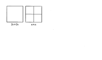
- FIG. 11 is a diagram illustrating an example of picture division.
- the square block shown in FIG. 11 is called LCU.
- the size of the LCU can be selected from 16 ⁇ 16 pixels, 32 ⁇ 32 pixels, and 64 ⁇ 64 pixels, but they are all the same in one picture.
- CU which is a unit for performing actual encoding, is a square block existing in a certain LCU, and a prediction mode is determined in units of CU.
- the CU is a block having the same size as the LCU, or a square block obtained by equally dividing the LCU into four as shown in FIG. 11, or obtained by repeatedly applying this four-division processing to the LCU. It is a square block.
- the size of the LCU is (2 to the power of N) ⁇ (2 to the power of N)
- the size of the CU is (2 to the power of M) ⁇ (2 to the power of M) (3 ⁇ M ⁇ N, where N and M Is an integer).
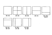
- PU is a unit for setting the prediction direction in the CU.
- 12A and 12B are diagrams illustrating examples of PU partition options (PU partition type). As shown in FIG. 12A, in the inter prediction, eight division methods can be selected. Also, as shown in FIG. 12B, in intra prediction, it is possible to select from two division methods only when the CU size is 8 ⁇ 8. Otherwise, PU is identical to CU. In order to improve the coding efficiency, it is necessary to appropriately divide each CU and set the prediction mode of each CU. In particular, as the size of the LCU increases, the degree of freedom in selecting a CU partitioning method and prediction mode increases, and an improvement in coding efficiency is expected by setting an appropriate CU partitioning and prediction mode. Since it is necessary to perform computation for all possible CUs, there is a problem that the amount of computation increases.
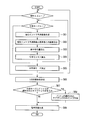
- FIG. 13 is a flowchart showing the processing operation of coding cost calculation for determining the shape of PU division within one CU.
- inter prediction is performed for each PU partition type (step S71). If the coding cost is minimized, the minimum coding cost, the shape of the PU partition that realizes the coding cost, and the inter prediction direction are stored (step S72).
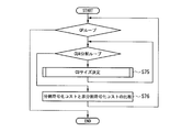
- FIG. 14 is a flowchart showing the processing operation of calculating the coding cost for selecting the CU partition size within one LCU. First, steps S71 to S74 shown in FIG. 13 are repeated in one CU, and the coding cost is calculated for all CUs to determine the CU size (step S75).
- the encoding cost when the CU is divided into four parts is compared with the encoding cost when the CU is not divided into four parts, and the CU division size that is the minimum encoding cost is selected, and the selected division size is stored (Step S76).
- FIG. 14 there is a description of a QP loop which is not described in the above description.
- a quantization parameter QP that determines a quantization step size can be set for each CU.
- the reference software includes a structure for calculating an optimal encoding cost while changing the value of the quantization parameter QP in order to realize this. For this reason, it is described as a QP loop in FIG.
- the process for selecting the optimum mode and the division shape and the division size for obtaining the minimum coding cost is referred to as an encoding optimization process.
- the expressions LCU and CU are used as the concept of the processing unit in HEVC, but more generally the equivalent to the LCU and CU including other encoding techniques are expressed as blocks and sub-blocks, respectively.
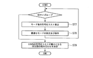
- FIG. 15 is a flowchart showing an encoding optimization processing operation.
- encoding costs for the inter prediction mode, the skip mode, and the intra prediction mode are calculated (step S77).
- an optimum mode is set and stored as a prediction mode of each CU size with the mode that minimizes the coding cost (step S78). This process is repeated for all CU sizes.
- a combination of CU divisions that minimizes the coding cost is determined (step S79).
- the encoding cost means an RD cost represented by the equation (1)
- RD cost D + ⁇ R (1)
- D is the sum of square errors of decoded pixels and original image pixels
- R is the amount of generated code
- ⁇ is a Lagrangian parameter.
- the pseudo RD cost in which D is replaced with the sum of absolute values D ′ of the prediction pixel and the original image pixel and R is replaced with the generated code amount R ′ other than the coefficient code amount
- the coding cost means a cost represented by an RD cost or a pseudo RD cost.
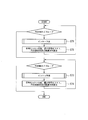
- FIG. 16 is a flowchart illustrating a processing operation for determining an optimal prediction direction for intra prediction. While selecting a certain prediction direction, the processes of steps S82 to S85 described below are repeated (step S81). First, an intra prediction image in the prediction direction is created using neighboring encoded pixels (step S82). Subsequently, an error between the pixel of the intra predicted image and the pixel of the original image is calculated (step S83).
- step S84 the generated code amount is calculated (step S84), and the coding cost is calculated from the error and the generated code amount (step S85). Then, steps S82 to S85 are repeated for each prediction direction. Finally, an optimal intra prediction direction is set by setting the direction in which the calculated coding cost is minimum as the intra prediction direction (step S86).
- a block having a certain size is divided into sub-blocks having an optimum sub-block size, and an optimum prediction mode is determined for each sub-block.
- an optimum prediction mode is determined for each sub-block.
- the encoding of the prediction error is not necessary for the calculation of R ′. Since a prediction image is used for the calculation, it is necessary to encode and decode neighboring pixels used for the calculation. Therefore, when calculating the optimal encoding cost for each sub-block size, the calculation processing is actually reduced only by the arithmetic encoding processing of the prediction error coefficient only by the acceleration using the pseudo RD cost, and the calculation amount It is necessary to perform a decoding process with many sub-block sizes.
- the generated code amount includes both the case where the generated code amount of the coefficient is included and the case where the generated code amount of the coefficient is not included.
- Non-Patent Document 1 As an example of speeding up by a conventional technique.
- Non-Patent Document 1 introduces a method of using pixels of an original image or pixels obtained by applying a filter to pixels of an original image as pixels of a pseudo intra prediction image. With this method, the reference pixels used for calculating the optimal intra prediction mode for each size of the sub-block are only the pixels of the original image or the pixels to which the filter is applied to the pixels of the original image. Can be reduced.
- a pixel of a pseudo intra prediction image is generated using a pixel of an original image or a pixel obtained by applying a fixed filter to a pixel of the original image as a pixel of a reference image for intra prediction.
- the quantization step size, the selected prediction mode, and the like that are considered to affect the original decoded image are not used only by using the pixels of the original image or the pixels obtained by applying the fixed filter to the pixels of the original image. Therefore, there is a problem that correct prediction and cost cannot be calculated.
- the present invention has been made in view of such circumstances, and provides an image encoding method, an image encoding device, and an image encoding program capable of reducing the amount of calculation in intra prediction of encoding optimization processing. For the purpose.
- a reference pixel generation unit that generates a reference pixel from a prediction pixel of a neighboring pixel and a pixel of an original image with respect to an intra prediction direction, and a pseudo intra prediction pixel is generated from the reference pixel and the intra prediction direction
- a pseudo intra prediction pixel generation unit that performs encoding that calculates an encoding cost for the intra prediction direction from an error between the pseudo intra prediction pixel and the pixel of the original image and a generated code amount when generating the pseudo intra prediction pixel It is an image coding apparatus provided with a cost calculation part and an intra prediction direction setting part which sets the intra prediction direction corresponding to the encoding cost which becomes the minimum among the said encoding costs as an optimal intra prediction direction.
- a skip mode determination unit that determines whether or not a prediction mode of a prediction pixel of a neighboring pixel with respect to an intra prediction direction is a skip mode, and a determination result of the skip mode determination unit is the skip mode
- the prediction pixel of the neighboring pixel is used as a reference pixel, an intra prediction pixel is generated from the reference pixel, and when the determination result is a mode other than the skip mode, the prediction pixel of the neighboring pixel and the original image
- An intra prediction pixel / pseudo intra prediction pixel generation unit that generates a reference pixel from the generated pixel and generates a pseudo intra prediction pixel from the generated reference pixel and the intra prediction direction, and the intra prediction pixel or the pseudo intra prediction pixel And pixel error of the original image and the intra prediction pixel or the pseudo intra prediction pixel
- An encoding cost calculation unit that calculates an encoding cost for the intra prediction direction from the generated code amount, and an intra that sets an intra prediction direction corresponding to a minimum encoding cost
- One aspect of the present invention includes a weighting coefficient generation unit that generates a weighting coefficient used when generating a pseudo intra prediction image from a quantization step size of a prediction pixel of a neighboring pixel with respect to an intra prediction direction, and prediction of the neighboring pixel Generating a reference pixel from the pixel and the pixel of the original image using the weighting coefficient, generating a pseudo intra prediction pixel from the reference pixel and the intra prediction direction, and the pseudo intra prediction pixel; An encoding cost calculation unit that calculates an encoding cost for the intra prediction direction from an error of the pixel of the original image and a generated code amount when generating the pseudo intra prediction pixel; and a code that is the smallest of the encoding costs And an intra prediction direction setting unit that sets an intra prediction direction corresponding to the cost of conversion as an optimal intra prediction direction.
- An image encoding device that generates a weighting coefficient used when generating a pseudo intra prediction image from a quantization step size of a prediction pixel of a neighbor
- the encoding cost for the intra prediction direction set in block units by the image encoding method is compared with the encoding cost for a mode other than the intra prediction mode, and the encoding cost for the optimal intra prediction direction is compared.
- intra prediction may be performed again using a neighboring decoded image.
- a reference pixel generation step that generates a reference pixel from a prediction pixel of a neighboring pixel and a pixel of an original image with respect to an intra prediction direction, and a pseudo intra prediction pixel is generated from the reference pixel and the intra prediction direction
- a pseudo-intra prediction pixel generation step and encoding for calculating an encoding cost for the intra-prediction direction from an error between the pseudo-intra prediction pixel and the pixel of the original image and a generated code amount when generating the pseudo-intra prediction pixel
- An image encoding method comprising: a cost calculating step; and an intra prediction direction setting step for setting an intra prediction direction corresponding to a minimum encoding cost among the encoding costs as an optimal intra prediction direction.
- One aspect of the present invention is an image encoding program for causing a computer to execute the image encoding method.
- the amount of encoding calculation can be reduced.
- FIG. 1 is a block diagram showing a configuration of an image encoding apparatus to which the present invention is applied.
- the image coding apparatus 100 includes an intra prediction processing unit 101, an inter prediction processing unit 102, a prediction residual signal generation unit (adding unit) 103, a transform processing unit 104, a quantization processing unit 105, an inverse quantization processing unit 106, and an inverse processing unit.
- a conversion processing unit 107, a decoded signal generation unit (adding unit) 108, a frame memory 109, a deblocking filter processing unit 110, an inter prediction information storage unit 111, an intra prediction information storage unit 112, and an entropy encoding processing unit 113 are provided.
- the configuration of the image encoding device 100 shown in FIG. 1 is equivalent to the HEVC video encoding processing block, and is a known configuration as described in Non-Patent Document 2, Non-Patent Document 3, and the like. Those contents are used as what constitutes a part of this specification, and detailed description thereof is omitted.
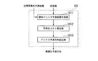
- FIG. 2 is a block diagram showing a detailed configuration of the intra prediction processing unit 101 shown in FIG.
- reference numeral 1011 denotes a pseudo intra prediction image generation unit that generates a pseudo intra prediction image.
- Reference numeral 1012 denotes an encoding cost calculation unit that calculates an encoding cost.
- Reference numeral 1013 denotes an intra prediction direction setting unit that sets an intra prediction direction.
- the intra prediction processing unit 101 uses, as reference pixels for intra prediction, pixels obtained using predicted pixels of neighboring pixels and pixels of the original image instead of decoded pixels.
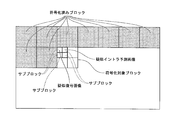
- FIG. 3 shows a case where the sub block in the upper left corner in the encoding target block has already calculated the encoding cost, and the encoding cost of the sub block adjacent to the right is the target of calculation. Show. The sub-block in the upper left corner has already been calculated for the coding cost, but the decoded image is not generated because the block shape has not yet been determined. For this reason, there is no decoded left adjacent pixel used for intra prediction.
- a pseudo-decoded image generated from the reference image (corresponding to the above-mentioned “predicted pixel of the neighboring pixel”) and the original image (“predicted pixel of the neighboring pixel and the original image described later”)
- the pseudo intra prediction image is generated from the pseudo decoded image and the intra prediction direction using the “reference pixel” in the “reference pixel obtained using the pixel”).
- the actual decoded image is generated at a timing after the block division shape of the entire decoding target block is determined (see, for example, FIGS. 6 and 10).
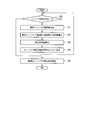
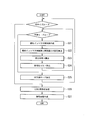
- FIG. 4 is a flowchart showing an intra prediction processing operation using a pseudo decoded image in the intra prediction processing unit 101 shown in FIG.
- the pseudo intra predicted image generation unit 1011 repeats the processes of steps S1 to S4 described below while selecting one intra prediction direction (step S0).
- the pseudo intra prediction image generation unit 1011 generates a pseudo intra prediction pixel from the reference pixel and the intra prediction direction obtained using the prediction pixel of the neighboring pixel and the pixel of the original image (step S1).
- the pseudo intra predicted image generation unit 1011 generates, as the pixel value of the reference pixel, the average value of the pixel values of the original image pixels at the same position as the pixel values of the predicted pixels of the neighboring pixels.
- the pseudo intra predicted image generation unit 1011 calculates an error from the pixel of the original image based on the generated pseudo intra predicted pixel (step S2). Then, the pseudo intra prediction image generation unit 1011 calculates the amount of generated code by the pseudo intra prediction pixel generation (step S3).
- the encoding cost calculation unit 1012 calculates the encoding cost for each intra prediction direction (step S4). After selecting all intra prediction directions, the intra prediction direction setting unit 1013 sets the intra prediction direction that minimizes the coding cost as the optimal intra prediction direction (step S5).
- pseudo intra prediction pixels are generated from reference pixels obtained by using neighboring prediction pixels and original image pixels instead of neighboring decoded pixels, and the cost for each prediction direction of intra prediction is reduced. calculate. This eliminates the need for the decoding process while deriving an appropriate prediction cost, and thus can reduce the amount of computation while suppressing a decrease in encoding efficiency in the encoding optimization process.
- FIG. 5 is a flowchart showing the operation of CU partitioning within 1 LCU and prediction mode determination processing in the conventional processing.
- an intra prediction image in each prediction mode is created using neighboring encoded pixels (step S11).
- an error between the pixel of the intra predicted image and the pixel of the original image is calculated (step S12).
- the generated code amount is calculated (step S13), and the encoding cost is calculated from the error and the generated code amount (step S14).
- Steps S11 to S14 are repeated for all prediction modes.
- the prediction mode that minimizes the coding cost is determined as the prediction mode for each CU size (step S15).
- a decoded image is generated according to the determined prediction mode (step S16). Steps S11 to S16 are repeated for all CU sizes.
- a combination of CU partitions that minimizes the coding cost is obtained, and an LCU partition shape is determined (step S17).
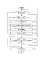
- FIG. 6 is a flowchart showing the operation of CU partitioning within 1 LCU and prediction mode determination processing according to this embodiment.
- a pseudo intra prediction pixel in each prediction mode is generated from the reference pixel obtained using the prediction pixel of the neighboring pixel and the pixel of the original image and the prediction mode (step S21).
- an error between the pixel of the generated pseudo intra prediction image and the pixel of the original image is calculated (step S22).
- the generated code amount is calculated (step S23), and the coding cost is calculated from the error and the generated code amount (step S24). Steps S21 to S24 are repeated for all prediction modes.
- the prediction mode that minimizes the coding cost is determined as the prediction mode for each CU size (step S25).
- Steps S21 to S25 are repeated for all CU sizes.
- a combination of CU divisions that minimizes the coding cost is obtained, and an LCU division shape is determined (step S26).
- a decoded image is generated according to the determined LCU division shape (step S27).
- step S16 of FIG. 6 it is necessary to generate a decoded pixel for each CU size as shown in step S16 of FIG.
- step S27 of FIG. 6 since it is not necessary to use a neighboring decoded pixel in each intra prediction, as shown in step S27 of FIG. 6, the generation of a decoded pixel needs to be performed only once for one LCU. As a result, the calculation amount is reduced.
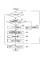
- FIG. 7 is a flowchart showing an intra prediction processing operation using a pseudo decoded image in the intra prediction processing unit 101 shown in FIG.
- a reference pixel is generated using a prediction pixel of a neighboring pixel and a pixel of an original image
- a pixel obtained in consideration of a prediction mode of the prediction pixel of the neighboring pixel is used.
- the pseudo intra predicted image generation unit 1011 repeats the processes of steps S32 to S37 described below while selecting one intra prediction direction (step S31).
- the pseudo intra prediction image generation unit 1011 determines whether or not the prediction mode of the prediction pixel of the neighboring pixels is the skip mode (step S32). As a result of this determination, “when the prediction mode of the prediction pixel of the neighboring pixels is the skip mode”, the pseudo intra prediction image generation unit 1011 generates an intra prediction pixel using the prediction pixel in the skip mode (step S33). .
- the pseudo intra prediction image generation unit 1011 uses the prediction pixel in the skip mode and the pixel in the original image.
- a pseudo intra prediction pixel is generated from the reference pixel obtained by using and the intra prediction direction (step S34).
- the pseudo intra predicted image generation unit 1011 generates, as the pixel value of the reference pixel, the average value of the pixel values of the original image pixels at the same position as the pixel values of the predicted pixels of the neighboring pixels.
- the pseudo intra prediction image generation unit 1011 calculates an error from the pixel of the original image based on the generated intra prediction pixel or pseudo intra prediction pixel (step S35). Then, the pseudo intra predicted image generation unit 1011 calculates a generated code amount by generating an intra prediction pixel or a pseudo intra prediction pixel (step S36).
- the encoding cost calculation unit 1012 calculates the encoding cost for each intra prediction direction (step S37). Then, the intra prediction direction setting unit 1013 sets the intra prediction direction that minimizes the coding cost as the optimal intra prediction direction (step S38).
- the neighboring decoded pixels are not used, but the prediction pixels of the neighboring pixels are switched according to the prediction mode of the neighboring pixels, and the switched pixels are used as the pseudo intra prediction pixels.
- step S33 when the prediction mode of the prediction pixel of the neighboring pixels is the skip mode, since the prediction pixel in the skip mode is a decoded pixel, it is expressed as “intra prediction image” instead of “pseudo intra prediction image”. Yes.
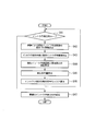
- FIG. 8 is a flowchart showing an intra prediction processing operation using a pseudo decoded image in the intra prediction processing unit 101 shown in FIG.
- the pseudo intra predicted image generation unit 1011 repeats the processes of steps S42 to S46 described below while selecting one intra prediction direction (step S41).
- the pseudo intra prediction image generation unit 1011 determines the weighting coefficient of the pseudo intra prediction pixel from the quantization step size of the neighboring pixels (step S42). For example, when the quantization step size is large, the weighting coefficient is determined by adjusting the weighting coefficient so that the weighting is larger for the predicted pixel of the neighboring pixel than the pixel of the original image. When the quantization step size is small, the weighting coefficient is determined by adjusting the weighting coefficient so that the weighting is larger for the pixels of the original image than the predicted pixels of the neighboring pixels.
- the pseudo intra prediction image generation unit 1011 generates a reference pixel from the prediction pixel of the neighboring pixel and the pixel of the original image by using a weighting coefficient, and performs pseudo prediction for each intra prediction direction from the generated reference pixel and the intra prediction direction. Intra prediction pixels are generated (step S43). Subsequently, the pseudo intra predicted image generation unit 1011 calculates an error from the pixel of the original image based on the generated pseudo intra predicted pixel (step S44). Then, the pseudo intra predicted image generation unit 1011 calculates the generated code amount by the pseudo intra predicted pixel generation (step S45).
- the encoding cost calculation unit 1012 calculates the encoding cost for each intra prediction direction (step S46). Then, the intra prediction direction setting unit 1013 sets the intra prediction direction that minimizes the coding cost as the optimal intra prediction direction (step S47).
- the reference pixel and the intra prediction direction obtained as a weighted sum of the neighboring prediction pixels based on the quantization step size and the pixels of the original image Pseudo intra prediction pixels are derived from and used.
- a decoding process is not necessary while deriving an appropriate encoding cost, so that it is possible to reduce the amount of computation while suppressing a decrease in encoding efficiency in the encoding optimization process.
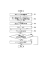
- FIG. 9 is a flowchart showing a processing operation for calculating the correct direction of intra prediction in the intra prediction direction setting unit 1013 shown in FIG.
- the process shown in FIG. 9 uses the pseudo intra prediction pixel calculated by the first to third embodiments and its encoding cost only for prediction mode determination, and when the optimal prediction mode of the sub-block is intra, After the sub-block size is determined, the correct direction of intra prediction is calculated again using the original decoded pixel as a reference pixel.
- the pseudo intra prediction image generation unit 1011 generates a pseudo intra prediction pixel from the reference pixel obtained using the prediction pixel of the neighboring pixel and the pixel of the original image and the intra prediction direction (step S51). Subsequently, the coding cost calculation unit 1012 calculates the coding cost in each intra prediction direction based on the generated pseudo intra prediction pixels (step S52).
- the intra prediction direction setting unit 1013 sets the direction that minimizes the coding cost as the provisional intra prediction direction (step S53).
- the intra prediction direction setting unit 1013 determines the prediction mode by comparing the coding costs for each prediction mode (step S54). And the intra prediction direction setting part 1013 determines the division
- the intra prediction direction setting unit 1013 determines whether or not there is a sub-block for which intra is selected in the prediction mode (step S56). When there is a sub-block for which intra is selected as the prediction mode, the intra-prediction direction setting unit 1013 calculates an actual decoded pixel for only the corresponding sub-block and performs intra-prediction, and the result is the intra-block of the sub-block. The prediction direction is saved (step S57).
- the sub-block size and the optimal prediction mode are determined based on the reference pixel obtained using the neighboring prediction pixel and the original image pixel instead of the neighboring decoded pixel and the intra prediction direction.
- Intra prediction pixels are derived and used. This eliminates the need for a decoding process while deriving an appropriate encoding cost.
- the calculation of the intra prediction direction is performed again only for the subblock for which the intra prediction is optimal. This makes it possible to perform more appropriate intra prediction without increasing unnecessary decoding processing. For this reason, the present embodiment can realize an improvement in encoding efficiency while suppressing an increase in the amount of encoding calculation with respect to the processes of the first to third embodiments.
- FIG. 10 is a flowchart illustrating the operation of CU partitioning within 1 LCU and prediction mode determination processing in the fourth embodiment.
- the processes in steps S61 to S66 and S69 are the same as the processes in steps S21 to S27 shown in FIG.
- the optimal prediction mode and the intra prediction result for determining the division shape and the division size are used as they are, when the optimal prediction mode of the sub-block is intra, an appropriate intra prediction direction is selected. It may not be.
- step S67 after determining the division shape of the block, it is determined whether there is a sub-block for which intra is selected in the prediction mode (step S67), and only when the optimal prediction mode is intra, As in step S68 in FIG. 10, the intra prediction direction is obtained again using the decoded pixels. For this reason, in the fourth embodiment, it is possible to perform more appropriate intra prediction while suppressing an increase in the amount of coding calculation compared to the first to third embodiments.
- the input image is divided into 64 ⁇ 64 pixel LCUs (hereinafter, 64 ⁇ 64 LCUs) (processing 1).
- the encoding cost of each prediction mode of the inter prediction mode and the skip mode is calculated for the N ⁇ N size CU in the upper left corner of the upper left LCU using the encoded frame, and the encoding is performed.
- the mode that minimizes the cost and the encoding cost C1 are stored (processing 2).
- a reference pixel is generated according to the prediction mode of the neighboring pixels (processing 3). If the prediction mode of the neighboring pixel is the skip mode, an intra prediction pixel of the encoding target CU is generated by applying a filter according to the direction of intra prediction to the prediction pixel of the neighboring pixel (processing 3-1). On the other hand, when the prediction mode of the neighboring pixel is other than the skip mode, the average value of the prediction pixel of the neighboring pixel and the pixel of the original image at the same position is calculated as a reference pixel, and the pixel value corresponds to the direction of intra prediction. A filter is applied to generate a pseudo intra prediction pixel of the encoding target CU (processing 3-2).
- the process 3 is performed for each intra prediction direction, the encoding cost C2 that is the minimum is compared with the encoding cost C1, and if the encoding cost C2 is small, the intra prediction direction and the encoding cost are stored. If the coding cost C1 is small, the coding cost C1 is stored in the coding cost C2 as it is (processing 4). That is, the loop process is advanced so that the minimum value is stored in the encoding cost C2.
- Processes 2 to 4 are repeated for each CU size 8 ⁇ 8 to 64 ⁇ 64, and the optimal prediction mode and its encoding cost are calculated for all CU sizes in the LCU at the upper left (Process 5).
- the encoding cost of the 16 ⁇ 16 pixel CU (hereinafter referred to as 16 ⁇ 16 CU) in the upper left corner and the encoding cost of the four 8 ⁇ 8 pixel CUs (hereinafter referred to as 8 ⁇ 8 CU) in the inside thereof.
- the sums are compared, and the one with the smaller coding cost is selected as the optimum CU, and the CU partition information, the prediction mode of each CU, and the coding cost are stored (processing 6).
- the process 6 is repeated for each 16 ⁇ 16 CU (process 7).
- the sum of the coding cost of a 64 ⁇ 64 pixel CU (hereinafter referred to as 64 ⁇ 64 CU) and the four 32 ⁇ 32 CU coding costs inside the CU is compared.
- the coding cost of the optimum CU selected in the process 8 is used as the coding cost of 32 ⁇ 32 CU.
- the one with the smaller coding cost is selected as the optimum CU, and the CU partition information, the prediction mode of each CU, and the coding cost are stored (process 10 above).
- processes 2 to 10 are repeated for each LCU (process 11).
- the input image is divided into 64 ⁇ 64 LCUs (process 21).
- the encoding cost of each prediction mode of the inter prediction mode and the skip mode is calculated for the N ⁇ N size CU in the upper left corner of the upper left LCU using the encoded frame, and the encoding is performed.
- the mode with the lowest cost and the encoding cost C1 are stored (process 22).
- a reference pixel is generated according to the prediction mode of the neighboring pixels (processing 23).
- the prediction mode of the neighboring pixel is the skip mode
- an intra prediction pixel of the encoding target CU is generated by applying a filter according to the direction of intra prediction to the prediction pixel of the neighboring pixel (processing 23-1).
- the prediction mode of the neighboring pixel is other than the skip mode
- a weighted sum based on the quantization step size of the neighboring pixel is calculated for the pixel of the original image at the same position as the prediction pixel of the neighboring pixel and used as a reference pixel.
- a filter corresponding to the direction of intra prediction is applied to the pixel value to generate a pseudo intra prediction pixel of the encoding target CU (process 23-2).
- the calculation method of the weighted sum is as follows.
- Process 23 is performed for each intra prediction direction, and the minimum encoding cost C2 and the encoding cost C1 are compared. If the encoding cost C2 is small, the intra prediction direction and the encoding cost are stored, and the encoding is performed. If the cost C1 is small, the encoding cost C1 is stored as it is in the encoding cost C2 (process 24). The processes 22 to 24 are repeated for each CU size 8 ⁇ 8 to 64 ⁇ 64, and the optimal prediction mode and the encoding cost thereof are calculated for the CUs of all sizes in the upper left LCU (process 25).
- the encoding cost of 16 ⁇ 16 CU in the upper left corner is compared with the sum of the encoding costs of four 8 ⁇ 8 CUs in the upper left corner, and the one with the smaller encoding cost is selected as the optimal CU.
- the information, the prediction mode of each CU, and the encoding cost are stored (process 26).
- the process 26 is repeated for each 16 ⁇ 16 CU (process 27).
- the sum of the encoding cost of 32 ⁇ 32 CU in the upper left corner and the encoding costs of the four 16 ⁇ 16 CUs inside it is compared.
- the encoding cost of the optimal CU selected in the process 26 is used as the encoding cost of 16 ⁇ 16 CU.
- the one with the smaller coding cost is selected as the optimum CU, and the CU partition information, the prediction mode of each CU, and the coding cost are stored (step 28). Then, the process 28 is repeated for each 32 ⁇ 32 CU (process 29).
- the sum of the 64 ⁇ 64 CU encoding cost and the four 32 ⁇ 32 CU encoding costs inside it is compared.
- the encoding cost of the optimum CU selected in the process 28 is used as the encoding cost of 32 ⁇ 32 CU.
- the one with the smaller coding cost is selected as the optimum CU, and the CU partition information, the prediction mode of each CU, and the coding cost are stored (processing 30).
- the processes 22 to 30 are repeated for each LCU (process 31).
- the input image is divided into 64 ⁇ 64 LCUs (process 41).
- the encoding cost of each prediction mode of the inter prediction mode and the skip mode is calculated using the encoded frame for the N ⁇ N size CU in the upper left corner in the upper left LCU, and the encoding cost is calculated.
- the encoding cost C1 is stored (process 42).
- reference pixels are generated according to the prediction mode of the neighboring pixels (processing 43). If the prediction mode of the neighboring pixels is the skip mode, an intra prediction pixel of the coding target CU is generated by applying a filter according to the direction of intra prediction to the prediction pixels of the neighboring pixels (processing 43-1). On the other hand, if the prediction mode of the neighboring pixel is other than the skip mode, a weighted sum based on the quantization step size of the neighboring pixel is calculated for the pixel of the original image at the same position as the prediction pixel of the neighboring pixel and used as a reference pixel. Then, a filter corresponding to the direction of intra prediction is applied to the pixel value to generate a pseudo intra prediction pixel of the encoding target CU (processing 43-2).
- the calculation method of the weighted sum is as follows.
- the processing 43 is performed for each intra prediction direction, the encoding cost C2 that is the minimum is compared with the encoding cost C1, and if the encoding cost C2 is small, the intra prediction direction and the encoding cost are stored. If the coding cost C1 is small, the coding cost C1 is stored as it is in the coding cost C2 (process 44).
- the processes 42 to 44 are repeated for each CU size 8 ⁇ 8 to 64 ⁇ 64, and the optimum prediction mode and the encoding cost thereof are calculated for the CUs of all sizes in the upper left LCU (process 45).
- the encoding cost of 16 ⁇ 16 CU in the upper left corner is compared with the sum of the encoding costs of four 8 ⁇ 8 CUs in the upper left corner, and the one with the smaller encoding cost is selected as the optimal CU.
- Information, the prediction mode of each CU, and the coding cost are stored (process 46). Then, the process 46 is repeated for each 16 ⁇ 16 CU (process 47).
- the 32 ⁇ 32 CU encoding cost in the upper left corner is compared with the sum of the four 16 ⁇ 16 CU encoding costs inside.
- the encoding cost of the optimal CU selected in the process 46 is used as the encoding cost of 16 ⁇ 16 CU.
- the one with the smaller coding cost is selected as the optimum CU, and the CU partition information, the prediction mode of each CU, and the coding cost are stored (step 48).
- the process 48 is repeated for each 32 ⁇ 32 CU (process 49).
- the sum of the 64 ⁇ 64 CU encoding cost and the four 32 ⁇ 32 CU encoding costs inside it is compared.
- the encoding cost of the optimum CU selected in the process 48 is used as the encoding cost of 32 ⁇ 32 CU.
- the one with the smaller coding cost is selected as the optimum CU, and the CU partition information, the prediction mode of each CU, and the coding cost are stored (process 50 above).
- the peripheral pixels are sequentially decoded in the fixed CU division size and mode.
- the optimum intra prediction direction is obtained and stored only for the intra prediction location (process 51). Then, the processes 42 to 51 are repeated for each LCU.
- the encoding cost for the pseudo intra prediction image generated from the prediction pixel of the neighboring pixel and the reference pixel obtained using the pixel of the original image and the intra prediction direction instead of the neighboring decoded pixel is calculated, By determining the optimal prediction direction based on the coding cost, it is possible to reduce the amount of calculation required for intra prediction.
- the intra prediction processing unit 101 in the above-described embodiment may be realized by a computer.
- the intra prediction processing unit 101 is realized by recording a program for realizing this function in a computer-readable recording medium, causing the computer system to read and execute the program recorded in the recording medium.
- the “computer system” includes hardware such as an OS (Operating System) and peripheral devices.
- “Computer-readable recording medium” means a portable medium such as a flexible disk, a magneto-optical disk, a ROM (Read Only Memory), a CD (Compact Disk) -ROM, or a hard disk built in a computer system. Refers to the device.
- the “computer-readable recording medium” dynamically holds a program for a short time like a communication line when transmitting a program via a network such as the Internet or a communication line such as a telephone line.
- a volatile memory inside a computer system serving as a server or a client in that case may be included and a program held for a certain period of time.
- the program may be a program for realizing a part of the functions described above, and may be a program capable of realizing the functions described above in combination with a program already recorded in a computer system.
- the intra prediction processing unit 101 may be realized by using hardware such as PLD (Programmable Logic Device) and FPGA (Field Programmable Gate Array).
- the present invention calculates a coding cost for a pseudo intra prediction image generated from a reference pixel and an intra prediction direction obtained using a prediction pixel of a neighboring pixel and a pixel of an original image instead of a neighboring decoded pixel, and the encoding By determining the optimal prediction direction based on the cost, the present invention can be applied to a use for reducing the amount of calculation required for intra prediction.
- Intra prediction processing unit 1011 ... Pseudo intra prediction image generation unit, 1012 ... Coding cost calculation unit, 1013 ... Intra prediction direction setting unit
Landscapes
- Engineering & Computer Science (AREA)
- Multimedia (AREA)
- Signal Processing (AREA)
- Computing Systems (AREA)
- Theoretical Computer Science (AREA)
- Compression Or Coding Systems Of Tv Signals (AREA)
Abstract
La présente invention porte sur un dispositif de codage d'image qui peut réduire la quantité de calcul imposée en prédiction interne dans un processus d'optimisation de codage. Le dispositif de codage d'image comporte : une unité de génération de pixels de référence pour générer des pixels de référence à partir de pixels d'une image originale et de pixels de prédiction de pixels proches, relativement à la direction de prédiction interne ; une unité de génération de pixels de pseudo-prédiction interne pour générer des pixels de référence et des pixels de pseudo-prédiction interne à partir de la direction de prédiction interne ; une unité de calcul de coût de codage pour calculer un coût de codage relativement à la direction de prédiction interne, à partir d'erreurs entre les pixels de pseudo-prédiction interne et les pixels de l'image originale, et de la quantité de symboles générés durant la génération des pixels de pseudo-prédiction interne ; et une unité de réglage de direction de prédiction interne pour régler, à tire de direction de prédiction interne optimale, la direction de prédiction interne qui correspond au coût de codage le plus bas parmi les coûts de codage.
Priority Applications (3)
| Application Number | Priority Date | Filing Date | Title |
|---|---|---|---|
| ES14829177T ES2717476T3 (es) | 2013-07-25 | 2014-07-22 | Método de codificación de imágenes, dispositivo de codificación de imágenes y programa de codificación de imágenes |
| EP14829177.6A EP3026915B1 (fr) | 2013-07-25 | 2014-07-22 | Procédé de codage d'image, dispositif de codage d'image et programme de codage d'image |
| US14/906,407 US10085018B2 (en) | 2013-07-25 | 2014-07-22 | Image encoding method, image encoding apparatus, and image encoding program |
Applications Claiming Priority (2)
| Application Number | Priority Date | Filing Date | Title |
|---|---|---|---|
| JP2013155034A JP5711789B2 (ja) | 2013-07-25 | 2013-07-25 | 画像符号化方法、画像符号化装置及び画像符号化プログラム |
| JP2013-155034 | 2013-07-25 |
Publications (1)
| Publication Number | Publication Date |
|---|---|
| WO2015012256A1 true WO2015012256A1 (fr) | 2015-01-29 |
Family
ID=52393291
Family Applications (1)
| Application Number | Title | Priority Date | Filing Date |
|---|---|---|---|
| PCT/JP2014/069296 Ceased WO2015012256A1 (fr) | 2013-07-25 | 2014-07-22 | Procédé de codage d'image, dispositif de codage d'image et programme de codage d'image |
Country Status (5)
| Country | Link |
|---|---|
| US (1) | US10085018B2 (fr) |
| EP (1) | EP3026915B1 (fr) |
| JP (1) | JP5711789B2 (fr) |
| ES (1) | ES2717476T3 (fr) |
| WO (1) | WO2015012256A1 (fr) |
Cited By (4)
| Publication number | Priority date | Publication date | Assignee | Title |
|---|---|---|---|---|
| CN114286108A (zh) * | 2021-12-31 | 2022-04-05 | 展讯通信(上海)有限公司 | 确定帧内编码模式的方法、装置、电子设备及存储介质 |
| CN114598890A (zh) * | 2019-12-10 | 2022-06-07 | Oppo广东移动通信有限公司 | 用于对图像进行编码和解码的方法以及相关装置和系统 |
| CN114615493A (zh) * | 2016-03-24 | 2022-06-10 | 英迪股份有限公司 | 视频解码方法、视频编码方法和可读记录介质 |
| JP7516793B2 (ja) | 2020-03-24 | 2024-07-17 | 日本電気株式会社 | 動画像符号化システムおよび動画像符号化方法 |
Families Citing this family (3)
| Publication number | Priority date | Publication date | Assignee | Title |
|---|---|---|---|---|
| JP7027044B2 (ja) * | 2017-04-27 | 2022-03-01 | キヤノン株式会社 | 画像符号化装置、画像符号化方法及びプログラム |
| KR102445899B1 (ko) * | 2017-12-29 | 2022-09-21 | 인텔렉추얼디스커버리 주식회사 | 서브-블록 단위 화면 내 예측을 사용하는 비디오 코딩 방법 및 장치 |
| CN113573066B (zh) * | 2021-07-07 | 2024-07-02 | 网宿科技股份有限公司 | 一种视频编码的方法及装置 |
Citations (4)
| Publication number | Priority date | Publication date | Assignee | Title |
|---|---|---|---|---|
| JP2008166916A (ja) * | 2006-12-27 | 2008-07-17 | Victor Co Of Japan Ltd | イントラ予測符号化装置およびイントラ予測符号化方法 |
| JP2008252346A (ja) * | 2007-03-29 | 2008-10-16 | Canon Inc | 画像符号化装置及び画像符号化方法 |
| JP2009290498A (ja) * | 2008-05-29 | 2009-12-10 | Renesas Technology Corp | 画像符号化装置及び画像符号化方法 |
| JP2013524670A (ja) * | 2010-04-09 | 2013-06-17 | シャープ株式会社 | イントラ予測方法およびイントラ予測システム |
Family Cites Families (3)
| Publication number | Priority date | Publication date | Assignee | Title |
|---|---|---|---|---|
| JP2005348280A (ja) * | 2004-06-07 | 2005-12-15 | Nippon Telegr & Teleph Corp <Ntt> | 画像符号化方法、画像符号化装置、画像符号化プログラム及びそのプログラムを記録したコンピュータ読み取り可能な記録媒体 |
| KR20100027384A (ko) * | 2008-09-02 | 2010-03-11 | 삼성전자주식회사 | 예측 모드 결정 방법 및 장치 |
| JP5713719B2 (ja) * | 2011-02-17 | 2015-05-07 | 株式会社日立国際電気 | 動画像符号化装置 |
-
2013
- 2013-07-25 JP JP2013155034A patent/JP5711789B2/ja active Active
-
2014
- 2014-07-22 ES ES14829177T patent/ES2717476T3/es active Active
- 2014-07-22 EP EP14829177.6A patent/EP3026915B1/fr active Active
- 2014-07-22 US US14/906,407 patent/US10085018B2/en active Active
- 2014-07-22 WO PCT/JP2014/069296 patent/WO2015012256A1/fr not_active Ceased
Patent Citations (4)
| Publication number | Priority date | Publication date | Assignee | Title |
|---|---|---|---|---|
| JP2008166916A (ja) * | 2006-12-27 | 2008-07-17 | Victor Co Of Japan Ltd | イントラ予測符号化装置およびイントラ予測符号化方法 |
| JP2008252346A (ja) * | 2007-03-29 | 2008-10-16 | Canon Inc | 画像符号化装置及び画像符号化方法 |
| JP2009290498A (ja) * | 2008-05-29 | 2009-12-10 | Renesas Technology Corp | 画像符号化装置及び画像符号化方法 |
| JP2013524670A (ja) * | 2010-04-09 | 2013-06-17 | シャープ株式会社 | イントラ予測方法およびイントラ予測システム |
Non-Patent Citations (3)
| Title |
|---|
| K. MCCANN; B. BROSS; W.-J. HAN; 1. K. KIM; K. SUGIMOTO; G. J. SULLIVAN: "High Efficiency Video Coding (HEVC) Test Model 15 (HM 15) Encoder Description", JOINT COLLABORATIVE TEAM ON VIDEO CODING (JCT-VC) DOCUMENT JCTVC-Q1002, March 2014 (2014-03-01) |
| SAKAE OKUBO; TERUHIKO SUZUKI; SEISHI TAKAMURA; TAKESHI CHUJO: "Impress standard textbook series H.265/HEVC textbook", 18 October 2013 |
| TAKAFUMI BANDO; NAOYUKI HIRAI; TIAN SONG; TAKASHI SHIMAMOTO: "New Prediction Modes for Parallel Processing of H.264/AVC", PROCEEDINGS OF INTERNATIONAL CONFERENCE ON MULTIMEDIA AND SIGNAL PROCESSING (CMSP' 11, May 2011 (2011-05-01), pages 344 - 347, XP002767512, DOI: doi:10.1109/CMSP.2011.76 |
Cited By (5)
| Publication number | Priority date | Publication date | Assignee | Title |
|---|---|---|---|---|
| CN114615493A (zh) * | 2016-03-24 | 2022-06-10 | 英迪股份有限公司 | 视频解码方法、视频编码方法和可读记录介质 |
| CN114598890A (zh) * | 2019-12-10 | 2022-06-07 | Oppo广东移动通信有限公司 | 用于对图像进行编码和解码的方法以及相关装置和系统 |
| US12382023B2 (en) | 2019-12-10 | 2025-08-05 | Guangdong Oppo Mobile Telecommunications Corp., Ltd. | Methods for encoding and decoding pictures and associated apparatus |
| JP7516793B2 (ja) | 2020-03-24 | 2024-07-17 | 日本電気株式会社 | 動画像符号化システムおよび動画像符号化方法 |
| CN114286108A (zh) * | 2021-12-31 | 2022-04-05 | 展讯通信(上海)有限公司 | 确定帧内编码模式的方法、装置、电子设备及存储介质 |
Also Published As
| Publication number | Publication date |
|---|---|
| JP2015026963A (ja) | 2015-02-05 |
| ES2717476T3 (es) | 2019-06-21 |
| EP3026915A1 (fr) | 2016-06-01 |
| EP3026915B1 (fr) | 2018-12-26 |
| US10085018B2 (en) | 2018-09-25 |
| US20160182904A1 (en) | 2016-06-23 |
| EP3026915A4 (fr) | 2017-04-05 |
| JP5711789B2 (ja) | 2015-05-07 |
Similar Documents
| Publication | Publication Date | Title |
|---|---|---|
| KR102165288B1 (ko) | 인루프 필터링을 적용한 예측 방법을 이용한 영상 부호화/복호화 방법 및 장치 | |
| KR102435393B1 (ko) | 참조 유닛 결정 방법 및 장치 | |
| WO2015012256A1 (fr) | Procédé de codage d'image, dispositif de codage d'image et programme de codage d'image | |
| JP2020205627A (ja) | インタ予測方法及びその装置 | |
| JP7428405B2 (ja) | インタ予測における融合モード候補のための大域的運動 | |
| CN102845060A (zh) | 用于视频的数据压缩 | |
| CN110870316A (zh) | 视频编码和解码中低复杂度双向帧内预测的方法和装置 | |
| WO2014087861A1 (fr) | Dispositif de traitement d'image, procédé de traitement d'image, et programme | |
| WO2019217122A1 (fr) | Procédé et appareil pour prédiction intra mélangée | |
| WO2017010073A1 (fr) | Dispositif de codage de film cinématographique, procédé de codage de film cinématographique, et support de stockage pour le stockage de programme de codage de film cinématographique | |
| JP4957780B2 (ja) | 動き補償予測符号化装置、動き補償予測符号化方法及びプログラム | |
| JP5339300B2 (ja) | 画像符号化方法、画像復号方法、画像符号化装置、画像復号装置、及びプログラム | |
| JP2025501981A (ja) | ブロックベースの映像コーディングのための符号予測 | |
| JP4438949B2 (ja) | 動き補償予測符号化装置、動き補償予測符号化方法及びプログラム | |
| JP6253564B2 (ja) | 画像符号化装置,画像復号装置,画像符号化方法,画像復号方法,画像符号化プログラムおよび画像復号プログラム | |
| CN119135891A (zh) | 视频编码方法、硬件编码器及视频编解码芯片 | |
| JP6130267B2 (ja) | 画像符号化方法、画像復号方法、画像符号化装置、画像復号装置、画像符号化プログラム及び画像復号プログラム | |
| JP2015179943A (ja) | 予測モードコスト計算方法及び予測モードコスト計算プログラム | |
| CN114302138A (zh) | 视频编解码中组合预测值确定 | |
| Chen et al. | Intra-frame prediction algorithm based on the H. 264/AVC research and improvement |
Legal Events
| Date | Code | Title | Description |
|---|---|---|---|
| 121 | Ep: the epo has been informed by wipo that ep was designated in this application |
Ref document number: 14829177 Country of ref document: EP Kind code of ref document: A1 |
|
| WWE | Wipo information: entry into national phase |
Ref document number: 14906407 Country of ref document: US |
|
| WWE | Wipo information: entry into national phase |
Ref document number: 2014829177 Country of ref document: EP |
|
| NENP | Non-entry into the national phase |
Ref country code: DE |