WO2015012402A1 - 空気入りラジアルタイヤ - Google Patents
空気入りラジアルタイヤ Download PDFInfo
- Publication number
- WO2015012402A1 WO2015012402A1 PCT/JP2014/069751 JP2014069751W WO2015012402A1 WO 2015012402 A1 WO2015012402 A1 WO 2015012402A1 JP 2014069751 W JP2014069751 W JP 2014069751W WO 2015012402 A1 WO2015012402 A1 WO 2015012402A1
- Authority
- WO
- WIPO (PCT)
- Prior art keywords
- tire
- center
- sipe
- land portion
- main groove
- Prior art date
- Legal status (The legal status is an assumption and is not a legal conclusion. Google has not performed a legal analysis and makes no representation as to the accuracy of the status listed.)
- Ceased
Links
Images


Classifications
-
- B—PERFORMING OPERATIONS; TRANSPORTING
- B60—VEHICLES IN GENERAL
- B60C—VEHICLE TYRES; TYRE INFLATION; TYRE CHANGING; CONNECTING VALVES TO INFLATABLE ELASTIC BODIES IN GENERAL; DEVICES OR ARRANGEMENTS RELATED TO TYRES
- B60C11/00—Tyre tread bands; Tread patterns; Anti-skid inserts
- B60C11/03—Tread patterns
- B60C11/04—Tread patterns in which the raised area of the pattern consists only of continuous circumferential ribs, e.g. zig-zag
-
- B—PERFORMING OPERATIONS; TRANSPORTING
- B60—VEHICLES IN GENERAL
- B60C—VEHICLE TYRES; TYRE INFLATION; TYRE CHANGING; CONNECTING VALVES TO INFLATABLE ELASTIC BODIES IN GENERAL; DEVICES OR ARRANGEMENTS RELATED TO TYRES
- B60C11/00—Tyre tread bands; Tread patterns; Anti-skid inserts
- B60C11/03—Tread patterns
- B60C11/12—Tread patterns characterised by the use of narrow slits or incisions, e.g. sipes
- B60C11/1272—Width of the sipe
-
- B—PERFORMING OPERATIONS; TRANSPORTING
- B60—VEHICLES IN GENERAL
- B60C—VEHICLE TYRES; TYRE INFLATION; TYRE CHANGING; CONNECTING VALVES TO INFLATABLE ELASTIC BODIES IN GENERAL; DEVICES OR ARRANGEMENTS RELATED TO TYRES
- B60C11/00—Tyre tread bands; Tread patterns; Anti-skid inserts
- B60C11/03—Tread patterns
- B60C2011/0337—Tread patterns characterised by particular design features of the pattern
- B60C2011/0339—Grooves
- B60C2011/0341—Circumferential grooves
- B60C2011/0344—Circumferential grooves provided at the equatorial plane
-
- B—PERFORMING OPERATIONS; TRANSPORTING
- B60—VEHICLES IN GENERAL
- B60C—VEHICLE TYRES; TYRE INFLATION; TYRE CHANGING; CONNECTING VALVES TO INFLATABLE ELASTIC BODIES IN GENERAL; DEVICES OR ARRANGEMENTS RELATED TO TYRES
- B60C11/00—Tyre tread bands; Tread patterns; Anti-skid inserts
- B60C11/03—Tread patterns
- B60C2011/0337—Tread patterns characterised by particular design features of the pattern
- B60C2011/0339—Grooves
- B60C2011/0341—Circumferential grooves
- B60C2011/0346—Circumferential grooves with zigzag shape
-
- B—PERFORMING OPERATIONS; TRANSPORTING
- B60—VEHICLES IN GENERAL
- B60C—VEHICLE TYRES; TYRE INFLATION; TYRE CHANGING; CONNECTING VALVES TO INFLATABLE ELASTIC BODIES IN GENERAL; DEVICES OR ARRANGEMENTS RELATED TO TYRES
- B60C11/00—Tyre tread bands; Tread patterns; Anti-skid inserts
- B60C11/03—Tread patterns
- B60C2011/0337—Tread patterns characterised by particular design features of the pattern
- B60C2011/0339—Grooves
- B60C2011/0341—Circumferential grooves
- B60C2011/0353—Circumferential grooves characterised by width
-
- B—PERFORMING OPERATIONS; TRANSPORTING
- B60—VEHICLES IN GENERAL
- B60C—VEHICLE TYRES; TYRE INFLATION; TYRE CHANGING; CONNECTING VALVES TO INFLATABLE ELASTIC BODIES IN GENERAL; DEVICES OR ARRANGEMENTS RELATED TO TYRES
- B60C11/00—Tyre tread bands; Tread patterns; Anti-skid inserts
- B60C11/03—Tread patterns
- B60C2011/0337—Tread patterns characterised by particular design features of the pattern
- B60C2011/0339—Grooves
- B60C2011/0381—Blind or isolated grooves
-
- B—PERFORMING OPERATIONS; TRANSPORTING
- B60—VEHICLES IN GENERAL
- B60C—VEHICLE TYRES; TYRE INFLATION; TYRE CHANGING; CONNECTING VALVES TO INFLATABLE ELASTIC BODIES IN GENERAL; DEVICES OR ARRANGEMENTS RELATED TO TYRES
- B60C11/00—Tyre tread bands; Tread patterns; Anti-skid inserts
- B60C11/03—Tread patterns
- B60C11/12—Tread patterns characterised by the use of narrow slits or incisions, e.g. sipes
- B60C11/1204—Tread patterns characterised by the use of narrow slits or incisions, e.g. sipes with special shape of the sipe
- B60C2011/1209—Tread patterns characterised by the use of narrow slits or incisions, e.g. sipes with special shape of the sipe straight at the tread surface
-
- B—PERFORMING OPERATIONS; TRANSPORTING
- B60—VEHICLES IN GENERAL
- B60C—VEHICLE TYRES; TYRE INFLATION; TYRE CHANGING; CONNECTING VALVES TO INFLATABLE ELASTIC BODIES IN GENERAL; DEVICES OR ARRANGEMENTS RELATED TO TYRES
- B60C11/00—Tyre tread bands; Tread patterns; Anti-skid inserts
- B60C11/03—Tread patterns
- B60C11/12—Tread patterns characterised by the use of narrow slits or incisions, e.g. sipes
- B60C11/1272—Width of the sipe
- B60C2011/1286—Width of the sipe being different from sipe to sipe
-
- B—PERFORMING OPERATIONS; TRANSPORTING
- B60—VEHICLES IN GENERAL
- B60C—VEHICLE TYRES; TYRE INFLATION; TYRE CHANGING; CONNECTING VALVES TO INFLATABLE ELASTIC BODIES IN GENERAL; DEVICES OR ARRANGEMENTS RELATED TO TYRES
- B60C2200/00—Tyres specially adapted for particular applications
- B60C2200/06—Tyres specially adapted for particular applications for heavy duty vehicles
Definitions
- the present invention relates to a pneumatic radial tire (hereinafter, also simply referred to as “tire”), and more particularly, to a pneumatic radial tire having improved stone biting resistance of a sipe provided in a tread portion.
- a tread pattern is formed on a tread portion of a pneumatic radial tire for the purpose of improving so-called wet performance such as drainage and steering stability when the vehicle travels on a wet road surface.
- wet performance there are a plurality of main grooves extending in the tire circumferential direction in the tread portion of the tire, and a plurality of lug grooves and sipes extending in the tire width direction in the land portion defined by the main grooves. It is generally performed.
- the main groove means a wide groove in the tread portion, and has a tread wear indicator that is a protrusion that can visually distinguish the degree of wear of the tread.
- an object of the present invention is to provide a pneumatic radial tire with improved stone biting resistance of a sipe provided in a tread portion, and preferably maintains stone performance in a main groove while maintaining wet performance. Improves biting ability.
- the present inventor assumes that the relationship between the circumferential sipe provided in the contact area of the tread portion and the inclined sipe that is inclined with respect to the tire circumferential direction is predetermined.
- the present inventors have found that the above-described problems can be solved by satisfying a predetermined relationship between the main groove extending in the tire circumferential direction and the lug groove extending incline in the tire circumferential direction, thereby completing the present invention. It was.
- the pneumatic radial tire of the present invention is a pneumatic radial tire having a land portion defined by at least three main grooves continuously extending in the tire circumferential direction in a contact area of a tread portion formed in an annular shape.
- a main groove on both outer sides in the tire width direction is a shoulder main groove
- a main groove on the inner side in the tire width direction from the shoulder main groove is a center main groove
- Shoulder land portion when the land portion formed on the inner side in the tire width direction than the shoulder land portion is a center land portion, a circumferential sipe extending in the tire circumferential direction on the shoulder land portion and the center land portion, and a tire
- An inclined sipe extending obliquely with respect to the circumferential direction, and a width Wa of the circumferential sipe and a width Wb of the inclined sipe are expressed by the following formula (1), Wa ⁇ Wb (1)
- the ground contact area means that the tire is mounted on a standard rim specified in JATMA YEAR BOOK (2008 edition, Japan Automobile Tire Association Standard), and the maximum load capacity (internal pressure) in the applicable size / ply rating in JATMA YEAR BOOK.
- -Contact surface of the tire when the internal pressure of 100% of the air pressure (maximum air pressure) corresponding to the load capacity correspondence table (bold load) is filled and 80% of the maximum load capacity is loaded.
- a plurality of lug grooves extending from the center main groove in an inclined direction with respect to the tire circumferential direction are provided, and the lug groove is substantially centered in the tire width direction of the center land portion.
- the circumferential sipe and the inclined sipe provided in a portion, and the depth of the lug groove in the communicating portion between the lug groove and the circumferential sipe, and the communicating portion between the inclined sipe It is preferable that the depth of the circumferential sipe and the inclined sipe is shallower.
- the depth of the circumferential sipe provided in the said center land part is deepest in the approximate center between the said lug grooves.
- the depth at the deepest portion of the circumferential sipe provided in the center land portion is the same as the depth at the deepest portion of the circumferential sipe provided in the shoulder land portion.
- a circumferential sipe provided on the shoulder land portion extends continuously in the tire circumferential direction.
- the width Wc of the center main groove and the width Ws of the shoulder main groove are expressed by the following formula (2), Wc ⁇ Ws (2) Satisfying the relationship represented by
- the center land portion has a plurality of lug grooves extending obliquely with respect to the tire circumferential direction from the center main groove, and an angle formed with the tire circumferential direction as the lug groove is separated from the center main groove. It is preferable that the lug groove becomes smaller and the depth of the lug groove becomes shallower as it goes away from the center main groove.
- the lug groove communicates with the circumferential sipe and the inclined sipe provided in the center land portion at approximately the center in the tire width direction of the center land portion. Furthermore, in the tire according to the present invention, it is preferable that the lug groove terminates at the center of the center land portion in the tire width direction. Moreover, in the tire of this invention, it is preferable that the said main groove has a linear part which has a width
- the present invention it is possible to provide a pneumatic radial tire with improved stone biting resistance of a sipe provided in a tread portion.
- the stone biting resistance of the main groove can be improved while maintaining the wet performance.
- FIG. 1 is a tire width direction sectional view of a pneumatic radial tire according to a preferred embodiment of the present invention.
- FIG. 1 is a developed plan view of a tread portion of a pneumatic radial tire according to a preferred embodiment of the present invention.
- the illustrated tire has at least three (three in the illustrated example) main grooves 1 continuously extending in the tire circumferential direction in the contact area W of the annularly formed tread portion 10 and the tire circumferential direction. And a lug groove 2 extending in an inclined manner.
- the main groove 1 has a zigzag shape extending in the circumferential direction.
- it may have a wave shape or a linear shape.
- the main grooves 1 on both outer sides in the tire width direction are the shoulder main grooves 1a and the tire main grooves 1a in the tire width direction.
- the main groove 1 on the inner side is the center main groove 1b, and the land portion 3 formed on the outer side in the tire width direction from the shoulder main groove 1a is formed on the shoulder land portion 3a and on the inner side in the tire width direction from the shoulder land portion 3a.
- the shoulder land portion 3a and the center land portion 3b are inclined with respect to the circumferential direction sipe 4 (4a, 4b in the illustrated example) extending in the tire circumferential direction and the tire circumferential direction.
- an inclined sipe 5 (in the illustrated example, 5a, 5b, 5c).
- the width Wa of the circumferential sipes 4a and 4b and the width Wb of the inclined sipes 5a, 5b and 5c are expressed by the following formula (1), Wa ⁇ Wb (1)
- the circumferential sipe 4 is shallower than the inclined sipe 5.
- the sipe opens and closes with the deformation of the stepping and kicking-out during the rolling of the tire in the inclined sipe 5 that inclines in the tire circumferential direction. Even if a stone is caught, it is easy to be discharged and it does not become a big problem. However, since the sipe 4 that extends in the circumferential direction does not open and close when the tire rolls, the stones sandwiched between the circumferential sipe 4 are not easily discharged.
- the circumferential sipe 4 is designed to be thinner and shallower than the inclined sipe 5 so that stones are not easily caught in the circumferential sipe 4 and the rigidity of the land portion 3 is increased. Reduced to prevent wear.
- Wa is 0.5 to 0.75 times Wb, and the depth of the circumferential sipe 4 is 0.7 to 0.9 times the depth of the inclined sipe 5.
- the lug groove 2 is provided in the land portion 3 as illustrated.
- a plurality of lug grooves 2a extending from the center main groove 1b in an inclined manner with respect to the tire circumferential direction are provided at equal intervals.
- the lug grooves 2a are formed on the center land portion 3b. It is preferable to terminate at approximately the center in the tire width direction.
- the lug grooves 2a are provided at substantially equal intervals.
- the lug grooves 2a are not limited to this, and the intervals between the lug grooves 2a may be arbitrary.
- a circumferential shear force acts on the center land portion 3b of the tread portion 10 in the traveling direction (driving direction), and the center land portion 3b is worn (center wear).
- the center land portion 3b is worn (center wear).
- the contact pressure tends to be released in the vicinity of the shoulder main groove 1a of the tread portion 10, so that a force in the braking direction works and the opening end of the shoulder main groove 1a wears preferentially. Riverware is likely to occur. Therefore, by terminating the lug groove 2a at the approximate center in the tire width direction of the center land portion 3b, the center wear and the river wear are suppressed at the same time without lowering the rigidity of the center land portion 3b more than necessary. This improves the wear appearance.
- the width of the lug groove 2a may be appropriately designed according to the use of the tire, and may be, for example, 3 mm to 6 mm.
- the approximate center in the tire width direction of the center land portion 3b refers to a region of 20% of the entire width in the width direction of the center land portion 3b with the center in the tire width direction of the center land portion 3b as the center.
- the lug groove 2a communicates with the circumferential sipe 4a and the inclined sipe 5a at the approximate center of the center land portion 3b, and in the communicating portion 6a between the lag groove 2a and the circumferential sipe 4a.
- the depth of the lug groove 2a and the depth of the lug groove 2a in the communication part 6b between the lug groove 2a and the inclined sipe 5a are shallower than the depths of the circumferential sipe 4a and the inclined sipe 5a in the communication parts 6a and 6b. preferable.
- the depth of the circumferential sipe 4a provided in the center land portion 3b is preferably deepest at the approximate center between the lug grooves 2a.
- the edge effect can be obtained while maintaining the rigidity of the center land portion 3b, and the wear resistance and the wet road surface can be improved.
- the approximate center between the lug grooves 2a refers to a region in the circumferential direction 20% of the distance L between the lug grooves 2a, with the center of the distance L between the lug grooves 2a as the center.
- the depth at the deepest portion of the circumferential sipe 4a provided in the center land portion 3b and the depth at the deepest portion of the circumferential sipe 4b provided in the shoulder land portion 3a are: Preferably they are the same. Thereby, traction balance can be maintained until the end of wear.
- the circumferential sipe 4b provided in the shoulder land portion 3a is a circumferential sipe that continuously extends in the tire circumferential direction.
- the shoulder land portion 3a of the tread portion 10 is likely to be worn. Therefore, in the tire of the present invention, the circumferential sipe provided on the shoulder land portion 3a is a circumferential sipe 4b that extends continuously in the circumferential direction, so that the wear that progresses from the shoulder progresses to the center region. It is preventing.
- the width Wc of the center main groove 1b and the width Ws of the shoulder main groove 1a are expressed by the following formula (2), Wc ⁇ Ws (2) It is preferable to satisfy the relationship represented by these.
- the lug groove 2 extending inclined with respect to the tire circumferential direction opens and closes with the deformation of the stepping and kicking out when the tire rolls. Even if it gets caught, it is easy to be discharged and it does not become a big problem.
- the main grooves 1a and 1b extending in the circumferential direction do not open and close when the tire rolls, stones caught in the grooves are not easily discharged.
- the center main groove 1b is less deformed in the tread portion during rolling of the tire than the shoulder main groove 1a, and it is difficult to discharge the bited stone.
- the center main groove 1b is designed to be thinner than the shoulder main groove 1a, so that stones are not easily caught.
- Wc is 0.75 to 0.9 times Ws.
- the depth of the main grooves 1a and 1b may be appropriately designed according to the use of the tire, and may be, for example, 7.5 to 11 mm.
- the tire of the present invention preferably has a structure in which the lug groove 2a formed in the center land portion 3b is inclined so that an angle formed with the tire circumferential direction decreases as the distance from the communicating center main groove 1b increases. .
- the lug groove 2a since the vicinity of the center main groove 1b of the lug groove 2a faces in the direction close to the tire width direction, the stones sandwiched in the vicinity of the center main groove 1b of the lug groove 2a are relatively easily discharged by rolling of the tire.
- the lug groove 2a faces a direction close to the tire circumferential direction, so that the pinched stone is difficult to be discharged.
- the depth of the lug groove 2a formed in the center land portion 3b is designed so as to become shallower as it goes away from the center main groove 1b, and the structure can be easily discharged even if a stone is caught in the tip of the lug 2a groove. It is said.
- the depth of the lug groove 2a is 6 to 11 mm at the point where it intersects with the center main groove 1b, and may be about 1.5 to 3 mm at the tip of the lug groove 2a.
- the width of the see-through portion S may be 0.3 to 0.6 times the width Wc of the center main groove 1b. It is generally known that when the main groove is provided at the center in the width direction of the tire, the steering stability is lowered. However, in the tire of the present invention, the width Wc of the center main groove 1b is the same as that of the shoulder main groove 1a. Since it is as narrow as 0.75 to 0.9 times the width Ws, the steering stability is not deteriorated.
- the tire according to the present invention relates to the improvement of the tread portion, and other than that, if the circumferential sipe 4a and the inclined sipe 5a provided in the center land portion 3b of the tread portion 10 satisfy the above relationship.
- an inclined sipe 5c that is inclined from the center main groove 1b and is not communicated with the lug groove 2a is provided, and the center main groove 1b and the lug groove 2a intersect. You may make it easier to discharge the stones between the points.
- the effect which raises an edge effect is acquired by providing the inclination sipes 5b and 5c.
- the shoulder main groove 1a may be provided with a lug groove 2b having an inclination with respect to the tire circumferential direction.
- This lug groove 2b can also enhance the edge effect in the circumferential direction.
- the inclined sipe 5b provided in the shoulder land portion 3a may be a sipe extending substantially outward in the tire width direction from the tip of the lug groove 2b.
- the shoulder land portion 3a may be appropriately provided with a groove 7 and an inclined sipe 5d according to the purpose.
- the negative rate which is the ratio of the total groove area to the entire surface of the tread portion 10
- the total area of the main groove 1 occupying the negative rate may be about 60 to 70%.
- the structure other than the tread portion 10 is not particularly limited, and a known member or a known material can be used.
- FIG. 3 is a cross-sectional view in the tire width direction of a pneumatic radial tire according to one preferred embodiment of the present invention.
- the illustrated tire 20 has a pair of left and right bead portions 12 and a pair of sidewall portions 13 in which the bead cores 11 are embedded, and a tread portion 10 connected to both sidewall portions 13, and spans between the pair of left and right bead cores 11.
- the carcass ply 14 extends in a toroidal shape and reinforces each part.
- three belt layers 15 a, 15 b, 15 c composed of rubberized layers of reinforcing cords arranged to be inclined with respect to the tire circumferential direction. Is arranged.
- the number of carcass plies 14 is one, but in the tire 20 of the present invention, the number of carcass plies 14 is not limited to this and may be two or more. Further, the structure is not particularly limited.
- the locking structure of the carcass ply 14 in the bead portion 12 is not limited to the structure in which the carcass ply 14 is wound around and locked around the bead core 11 as shown in the drawing, and may be a structure in which the end portion of the carcass ply is sandwiched between two layers of bead cores ( Not shown).
- the belt layers 15a, 15b and 15c are made of a rubberized layer of cord, preferably a steel corded rubberized layer extending with an inclination of ⁇ 15 to ⁇ 40 ° with respect to the tire circumferential direction, for example.
- the belt layers 15a, 15b, and 15c of the three layers are laminated so that the cords constituting each belt layer intersect with each other across the tire equatorial plane, thereby forming a crossing layer. It is not restricted to the example to do.
- an inner liner is usually disposed in the innermost layer of the tire 20.
- an inert gas such as nitrogen can be used as the gas filled in the tire 20 as the gas filled in the tire 20.
- Examples 1-1 and 1-2 and Conventional Example 1> A tread pattern tire having three zigzag main grooves as shown in FIG. 1 was produced with a tire size of 195 / 70R15.
- the width of the center main groove was 7 mm, and the width of the shoulder main groove was 7 mm.
- the center main groove 1b was disposed on the tire equator, and the shoulder main groove 1a was disposed at a position of 47% of the full width in the tire width direction centered on the center of the tread portion 10.
- the depth (mm) of the lug groove 2a is as shown in Table 1.
- the depth of the main groove was 9.5 mm
- the depth of the lug groove was 7 mm
- the end position of the lug groove was the center of the center land portion in the tire width direction.
- the deepest part of the circumferential sipe 4a was provided in the approximate center between lug grooves.
- Each tire obtained was incorporated into a rim (rim width: 6J), filled with an internal pressure of 450 kPa, mounted on a vehicle, and applied with a load of 6.0 kPa, with respect to stone biting resistance, wetness and wear resistance. Evaluation was performed according to the following procedure.
- the depth of the lug groove 2a gradually decreases so that the depth at the communication portion 6a between the main groove 1b and the lug groove 2a is 7 mm, and the depth is 2 mm at the approximate center of the center land portion 3b.
- Table 1 shows that the pneumatic radial tire of the present invention has improved stone biting resistance of the sipe provided in the tread portion.
- Example 2 A tread pattern tire having three zigzag main grooves as shown in FIG. 1 was produced with a tire size of 195 / 70R15.
- the center main groove 1b is disposed on the tire equator, and the shoulder main groove 1a is disposed at a position of 47% in width with the center in the width direction of the tread portion 10 as the center.
- Table 2 shows the width of the center main groove Wc, the width of the shoulder main groove Ws, the end position of the lug groove, the circumferential sipe, the inclined sipe, and the width of the see-through portion.
- the depth of the main groove was 9.5 mm.
- Each tire obtained was assembled into a rim (rim width: 6J), filled with an internal pressure of 450 kPa, mounted on the vehicle, and applied with a load of 6.00 kPa. Evaluation was performed according to the following procedure.
Landscapes
- Engineering & Computer Science (AREA)
- Mechanical Engineering (AREA)
- Tires In General (AREA)
Abstract
トレッド部に設けられたサイプの耐石噛み性を向上させた空気入りラジアルタイヤを提供する。 環状に形成されたトレッド部10の接地領域Wに、タイヤ周方向に連続して延びる少なくとも3本の主溝1により区画された陸部3を有し、タイヤ幅方向両外側の主溝をショルダー主溝1a、ショルダー主溝1aよりもタイヤ幅方向内側にある主溝をセンター主溝1bとし、ショルダー主溝1aよりもタイヤ幅方向外側に形成された陸部をショルダー陸部3a、ショルダー陸部3aよりもタイヤ幅方向内側に形成された陸部をセンター陸部3bとしたとき、ショルダー陸部3aおよびセンター陸部3bに、タイヤ周方向に延びる周方向サイプ4と、タイヤ周方向に対して傾斜して延びる傾斜サイプ5と、が設けられ、周方向サイプ4の幅Waと、傾斜サイプ5の幅Wbとが、Wa<Wbで表される関係を満足し、かつ、周方向サイプ4が傾斜サイプ5よりも浅い。
Description
本発明は、空気入りラジアルタイヤ(以下、単に「タイヤ」とも称する)に関し、詳しくは、トレッド部に設けられたサイプの耐石噛み性を向上させた空気入りラジアルタイヤに関する。
一般に、空気入りラジアルタイヤのトレッド部には、車両が湿潤路面を走行する際における排水性や操縦安定性等のいわゆるウェット性能を高める目的で、トレッドパターンが形成されている。ウェット性能を向上させる手法としては、タイヤのトレッド部にタイヤ周方向に延びる複数本の主溝と、この主溝により区画された陸部にタイヤ幅方向に延びる複数本のラグ溝やサイプ等を設けることが一般的に行われている。ここで主溝とは、トレッド部にある幅広い溝をいい、その内部にトレッドの摩耗の度合いが目視により判別できる突起物であるトレッドウェアインジケーターを有するものをいう。
このようなタイヤ周方向の主溝やタイヤ幅方向のラグ溝、サイプ等を有するタイヤにおいては、これらの溝やサイプに石が挟まること(石噛み)がある。石噛みが生じると、石の食い込み摩耗の進展とともに、石により溝底に亀裂が入る、いわゆるストーンドリリングが発生することがある。ストーンドリリングにより主溝の溝底がカットされると、ベルト層が破損し、トレッド部とベルト層のセパレーションに至る場合がある。そのため、従来は、溝底にストーンリジェクターと呼ばれる突起部を設けて、溝への石の噛み込みの防止を図っていた(例えば、特許文献1)。
従来、リブパターンを基調とするライトトラック用タイヤ等においては、トレッド部の溝や、タイヤ周方向に延びるサイプ、タイヤ幅方向に延びるサイプ等を活用して、ウェット性能や耐石噛み性等の改善を図ってきた。しかしながら、トレッド部に設けられたサイプの耐石噛み性に関する検討は十分になされていないのが現状であり、また、ウェット性能と溝の耐石噛み性とを同時に改善することは困難であった。例えば、タイヤ周方向に延びる主溝の耐石噛み性の改善を狙って、主溝にストーンリジェクターを設けると、排水性が悪化してしまうといった問題が生じてしまう。このように、従来のタイヤにおいては、耐石噛み性とウェット性能とを両立させることは困難であり、さらなる検討の余地が残されていた。
そこで、本発明の目的は、トレッド部に設けられたサイプの耐石噛み性を向上させた空気入りラジアルタイヤを提供することにあり、好ましくは、ウェット性能を維持しつつ、主溝の耐石噛み性を向上させる。
本発明者は、上記課題を解消するために鋭意検討した結果、トレッド部の接地領域に設けられた周方向サイプとタイヤ周方向に対して傾斜する傾斜サイプとの関係を所定のものとすることにより、また、タイヤ周方向に延びる主溝およびタイヤ周方向に傾斜して延びるラグ溝が所定の関係を満足することにより、上記課題を解消することができることを見出し、本発明を完成するに至った。
すなわち、本発明の空気入りラジアルタイヤは、環状に形成されたトレッド部の接地領域に、タイヤ周方向に連続して延びる少なくとも3本の主溝により区画された陸部を有する空気入りラジアルタイヤにおいて、
タイヤ幅方向両外側の主溝をショルダー主溝、該ショルダー主溝よりもタイヤ幅方向内側にある主溝をセンター主溝とし、前記ショルダー主溝よりもタイヤ幅方向外側に形成された陸部をショルダー陸部、該ショルダー陸部よりもタイヤ幅方向内側に形成された陸部をセンター陸部としたとき、前記ショルダー陸部および前記センター陸部に、タイヤ周方向に延びる周方向サイプと、タイヤ周方向に対して傾斜して延びる傾斜サイプと、が設けられ、前記周方向サイプの幅Waと、前記傾斜サイプの幅Wbとが、下記式(1)、
Wa<Wb (1)
で表される関係を満足し、かつ、前記周方向サイプが前記傾斜サイプよりも浅いことを特徴とするものである。
タイヤ幅方向両外側の主溝をショルダー主溝、該ショルダー主溝よりもタイヤ幅方向内側にある主溝をセンター主溝とし、前記ショルダー主溝よりもタイヤ幅方向外側に形成された陸部をショルダー陸部、該ショルダー陸部よりもタイヤ幅方向内側に形成された陸部をセンター陸部としたとき、前記ショルダー陸部および前記センター陸部に、タイヤ周方向に延びる周方向サイプと、タイヤ周方向に対して傾斜して延びる傾斜サイプと、が設けられ、前記周方向サイプの幅Waと、前記傾斜サイプの幅Wbとが、下記式(1)、
Wa<Wb (1)
で表される関係を満足し、かつ、前記周方向サイプが前記傾斜サイプよりも浅いことを特徴とするものである。
ここで接地領域とは、タイヤをJATMA YEAR BOOK(2008年度版、日本自動車タイヤ協会規格)に規定されている標準リムに装着し、JATMA YEAR BOOKでの適用サイズ・プライレーティングにおける最大負荷能力(内圧-負荷能力対応表の太字荷重)に対応する空気圧(最大空気圧)の100%の内圧を充填し、最大負荷能力の80%を負荷したときのタイヤの接触面をいう。
本発明のタイヤにおいては、前記センター主溝からタイヤ周方向に対して傾斜して延びる複数本のラグ溝が設けられ、前記ラグ溝が、前記センター陸部のタイヤ幅方向略中央で前記センター陸部に設けられた前記周方向サイプおよび前記傾斜サイプと連通してなり、かつ、前記ラグ溝と前記周方向サイプとの連通部、および前記傾斜サイプとの連通部におけるラグ溝の深さが、前記周方向サイプおよび前記傾斜サイプの深さよりも浅いことが好ましい。また、本発明のタイヤにおいては、前記センター陸部に設けられた周方向サイプの深さが、前記ラグ溝間の略中央で最も深いことが好ましい。さらに、本発明のタイヤにおいては、前記センター陸部に設けられた周方向サイプの最も深い部分における深さと、前記ショルダー陸部に設けられた周方向サイプの最も深い部分における深さと、が同じであることが好ましい。さらにまた、本発明のタイヤにおいては、前記ショルダー陸部に設けられた周方向サイプが、タイヤ周方向に向かって連続して延びることが好ましい。
また、本発明のタイヤにおいては、前記センター主溝の幅Wcと、前記ショルダー主溝の幅Wsとが、下記式(2)、
Wc<Ws (2)
で表される関係を満足し、
前記センター陸部が、前記センター主溝からタイヤ周方向に対して傾斜して延びる複数本のラグ溝を有し、該ラグ溝が、前記センター主溝から離れるにつれてタイヤ周方向とのなす角度が小さくなり、かつ、前記ラグ溝の深さが、前記センター主溝から離れるにつれて浅くなることが好ましい。
Wc<Ws (2)
で表される関係を満足し、
前記センター陸部が、前記センター主溝からタイヤ周方向に対して傾斜して延びる複数本のラグ溝を有し、該ラグ溝が、前記センター主溝から離れるにつれてタイヤ周方向とのなす角度が小さくなり、かつ、前記ラグ溝の深さが、前記センター主溝から離れるにつれて浅くなることが好ましい。
さらに、本発明のタイヤにおいては、前記ラグ溝が、前記センター陸部のタイヤ幅方向略中央で前記センター陸部に設けられた前記周方向サイプおよび前記傾斜サイプと連通してなることが好ましい。さらにまた、本発明のタイヤは、前記ラグ溝が前記センター陸部のタイヤ幅方向略中央で終端していることが好ましい。また、本発明のタイヤにおいては、前記主溝が周方向に幅を有する直線部を有することが好ましい。
本発明によれば、トレッド部に設けられたサイプの耐石噛み性を向上させた空気入りラジアルタイヤを提供することができる。また、好ましくは、ウェット性能を維持しつつ、主溝の耐石噛み性を向上させることができる。
以下、本発明の実施の形態を図面を用いて詳細に説明する。
図1は、本発明の一好適な実施の形態に係る空気入りラジアルタイヤのトレッド部の展開平面図である。図示するタイヤは、環状に形成されたトレッド部10の接地領域Wに、タイヤ周方向に連続して延びる少なくとも3本(図示例においては3本)の主溝1と、タイヤ周方向に対して傾斜して延びるラグ溝2と、を有する。図示例においては、主溝1は、周方向に延びるジグザグ形状であるが、本発明のタイヤにおいては、波型形状であってもよいし、直線形状であってもよい。
図1は、本発明の一好適な実施の形態に係る空気入りラジアルタイヤのトレッド部の展開平面図である。図示するタイヤは、環状に形成されたトレッド部10の接地領域Wに、タイヤ周方向に連続して延びる少なくとも3本(図示例においては3本)の主溝1と、タイヤ周方向に対して傾斜して延びるラグ溝2と、を有する。図示例においては、主溝1は、周方向に延びるジグザグ形状であるが、本発明のタイヤにおいては、波型形状であってもよいし、直線形状であってもよい。
本発明のタイヤにおいては、トレッド部10の接地領域W内の少なくとも3本の主溝1のうち、タイヤ幅方向両外側の主溝1をショルダー主溝1a、ショルダー主溝1aよりもタイヤ幅方向内側にある主溝1をセンター主溝1bとし、ショルダー主溝1aよりもタイヤ幅方向外側に形成された陸部3をショルダー陸部3a、ショルダー陸部3aよりもタイヤ幅方向内側に形成された陸部3をセンター陸部3bとしたとき、ショルダー陸部3aおよびセンター陸部3bに、タイヤ周方向に延びる周方向サイプ4(図示例においては4a、4b)と、タイヤ周方向に対して傾斜して延びる傾斜サイプ5(図示例においては5a、5b、5c)と、が設けられている。本発明のタイヤにおいては、周方向サイプ4a、4bの幅Waと、傾斜サイプ5a、5b、5cの幅Wbとが、下記式(1)、
Wa<Wb (1)
で表される関係を満足し、かつ、周方向サイプ4は傾斜サイプ5よりも浅い。
Wa<Wb (1)
で表される関係を満足し、かつ、周方向サイプ4は傾斜サイプ5よりも浅い。
トレッド部10の接地領域Wに設けられたサイプにおける石噛みについては、タイヤ周方向に傾斜して延びる傾斜サイプ5は、タイヤ転動時の踏み込みと蹴り出しの変形に伴い、サイプが開閉するため、石が挟まっても排出されやすく、大きな問題になることはない。しかしながら、周方向に延びる周方向サイプ4は、タイヤ転動時にサイプが開閉することはないため、周方向サイプ4に挟まった石は排出されにくい。そこで、本発明のタイヤにおいては、周方向サイプ4を傾斜サイプ5と比較して細く、かつ、浅く設計することで、周方向サイプ4に石が挟まりにくくし、また、陸部3の剛性を低下させて摩耗を防止している。好適にはWaはWbの0.5~0.75倍であり、周方向サイプ4の深さは、傾斜サイプ5の深さの0.7~0.9倍である。
本発明のタイヤにおいては、図示するように、陸部3にラグ溝2が設けられていることが好ましい。例えば、図示例では、センター主溝1bからタイヤ周方向に対して傾斜して延びる複数本のラグ溝2aが等間隔で設けられているが、この場合、ラグ溝2aは、センター陸部3bのタイヤ幅方向略中央で終端していることが好ましい。センター陸部3bにラグ溝2aを設けると、センター陸部3bの剛性が低下するため、溝に挟まった石が排出されやすくなり、耐石噛み性が向上するという効果が得られる。また、同時に、ラグ溝2aによりエッジ効果が生じて、トラクション性能も向上する。なお、図示例ではラグ溝2aは略等間隔で設けられているが、本発明においては、これに限られるものではなく、ラグ溝2aの間隔は任意の間隔でよい。
一般に、ライトトラックにおいては、トレッド部10のセンター陸部3bには周方向せん断力が進行方向(ドライビング方向)に働き、センター陸部3bが摩耗(センター摩耗)することになるが、センター陸部3bにラグ溝2aを設けることで、センター陸部のゴムの変形により、周方向せん断力を進行方向と逆の方向(ブレーキング方向)にし、センター摩耗を防止することができる。
一方、ライトトラックにおいては、トレッド部10のショルダー主溝1a付近では接地圧が抜ける傾向にあるため、ブレーキング方向の力が働き、ショルダー主溝1aの開口端部が優先的に摩耗する、いわゆるリバーウェアが生じやすくなる。そこで、ラグ溝2aをセンター陸部3bのタイヤ幅方向略中央で終端させることで、センター陸部3bの剛性を必要以上に低下させず、センター摩耗とリバーウェアとを同時に抑制している。これにより摩耗外観が向上する。本発明のタイヤにおいては、ラグ溝2aの幅は、タイヤの用途に合わせて適宜設計すればよく、例えば、3mm~6mmとすることができる。ここで、センター陸部3bのタイヤ幅方向略中央とは、センター陸部3bのタイヤ幅方向中央を中心とした、センター陸部3bの幅方向全幅の20%の領域をいう。
本発明のタイヤにおいては、ラグ溝2aが、センター陸部3bの略中央で周方向サイプ4aおよび傾斜サイプ5aと連通してなり、かつ、ラグ溝2aと周方向サイプ4aとの連通部6aにおけるラグ溝2aの深さ、およびラグ溝2aと傾斜サイプ5aとの連通部6bにおけるラグ溝2aの深さが、連通部6a、6bにおける周方向サイプ4aおよび傾斜サイプ5aの深さよりも浅いことが好ましい。連通部6a、6bにおけるラグ溝2aの深さを浅くすることで、連通部6a、6bにおける剛性を確保することができ、耐摩耗性を良好に確保することができる。また、ラグ溝2aを浅くすることで、連通部6a、6b近傍においてラグ溝2aの耐石噛み性も向上させることができる。
また、本発明のタイヤおいては、センター陸部3bに設けられた周方向サイプ4aの深さは、ラグ溝2a間の略中央で最も深いことが好ましい。ラグ溝2a同士の間隔Lの略中央で周方向サイプ4aを最も深くすることで、センター陸部3bの剛性を維持しつつ、エッジ効果を得ることができ、耐摩耗性と湿潤路面走行時の操縦安定性を向上させることができる。ここで、ラグ溝2a間の略中央とは、ラグ溝2a同士の間隔Lの中央を中心とした、ラグ溝2a同士の間隔Lの周方向20%の領域をいう。
さらに、本発明のタイヤにおいては、センター陸部3bに設けられた周方向サイプ4aの最も深い部分における深さと、ショルダー陸部3aに設けられた周方向サイプ4bの最も深い部分における深さと、が同じであることが好ましい。これにより、摩耗末期までトラクションバランスを保つことができる。
さらにまた、本発明のタイヤにおいては、ショルダー陸部3aに設けられた周方向サイプ4bは、タイヤ周方向に向かって連続して延びる周方向サイプとするのが好ましい。本発明のタイヤをライトトラック等のフロントタイヤに用いた場合、一般的にトレッド部10のショルダー陸部3aに摩耗が発生しやすい。そこで、本発明のタイヤにおいて、ショルダー陸部3aに設けられた周方向サイプを周方向に連続して延びる周方向サイプ4bとすることで、ショルダーから進展する摩耗が、センター領域に進展することを防止している。
また、本発明のタイヤにおいては、センター主溝1bの幅Wcと、ショルダー主溝1aの幅Wsとが、下記式(2)、
Wc<Ws (2)
で表される関係を満足することが好ましい。
Wc<Ws (2)
で表される関係を満足することが好ましい。
トレッド部10に設けられた溝における石噛みについては、タイヤ周方向に対して傾斜して延びるラグ溝2は、タイヤ転動時の踏み込みと蹴り出しの変形に伴い、溝が開閉するため、石が挟まっても排出されやすく、大きな問題になることない。しかしながら、周方向に延びる主溝1a、1bは、タイヤ転動時に溝が開閉することはないため、溝に挟まった石は排出されにくい。また、センター主溝1bは、ショルダー主溝1aと比較して、タイヤ転動時にトレッド部の変形が少なく、噛み込んだ石を排出しにくい。そこで、本発明のタイヤにおいては、センター主溝1bをショルダー主溝1aと比較して細く設計することで、石が挟まりにくくしている。好適にはWcはWsの0.75~0.9倍である。なお、主溝1a、1bの深さについては、タイヤの用途に合わせて適宜設計すればよく、例えば、7.5~11mmとすることができる。
さらに、本発明のタイヤは、センター陸部3bに形成されたラグ溝2aは、連通するセンター主溝1bから離れるにつれてタイヤ周方向とのなす角が小さくなるように傾斜する構造とするのが好ましい。この場合、ラグ溝2aのセンター主溝1b近傍はタイヤ幅方向に近い方向に向いているため、ラグ溝2aのセンター主溝1b近傍に挟まった石はタイヤの転動により比較的容易に排出される。しかしながら、ラグ溝2aの先端近傍においては、ラグ溝2aはタイヤ周方向に近い方向を向いているため、挟まれた石は排出されにくい。そこで、センター陸部3bに形成されたラグ溝2aの深さを、センター主溝1bから離れるにつれて浅くなるように設計し、ラグ2a溝の先端部に石が挟まっても容易に排出される構造としている。かかる効果を良好に得るためにはラグ溝2aの深さは、センター主溝1bと交わる点において6~11mmであり、ラグ溝2aの先端で1.5~3mm程度とすればよい。
また、タイヤにおいては湿潤路面におけるウェット性能を考えると、排水性も考慮に入れなければならない。そこで、本発明のタイヤにおいては、湿潤路面走行時における排水性を十分に確保するために、センター主溝1bにはタイヤ周方向に直線状に水が通過する、いわゆるシースルー部Sを設けることが好ましい(図1参照)。本発明のタイヤにおいては、シースルー部Sの幅は、センター主溝1bの幅Wcの0.3~0.6倍とすればよい。なお、タイヤの幅方向中央に主溝を設けた場合、操縦安定性が低下することが一般に知られているが、本発明のタイヤにおいては、センター主溝1bの幅Wcはショルダー主溝1aの幅Wsの0.75~0.9倍と細いため、操縦安定性を悪化させることはない。
本発明のタイヤは、トレッド部の改良に係るものであり、トレッド部10のセンター陸部3bに設けられた周方向サイプ4aと傾斜サイプ5aとが上記関係を満足するものであれば、それ以外に、特に制限はない。本発明のタイヤにおいては、図示するように、センター主溝1bから、タイヤ周方向に対して傾斜した、ラグ溝2aと連通しない傾斜サイプ5cを設けて、センター主溝1bとラグ溝2aの交差する点に挟まった石を排出しやすくしてもよい。また、傾斜サイプ5b、5cを設けることで、エッジ効果を高める効果が得られる。さらに、本発明のタイヤにおいては、ショルダー主溝1aに、タイヤ周方向に対して傾斜を有するラグ溝2bを設けてもよい。このラグ溝2bによっても、周方向のエッジ効果を高めることができる。さらにまた、図示するように、ショルダー陸部3aに設けられた傾斜サイプ5bは、ラグ溝2bの先端から、略タイヤ幅方向外側に延びるサイプとしてもよい。また、ショルダー陸部3aには、図示するように、その目的に応じて、適宜溝7や傾斜サイプ5dを設けてもよい。
また、本発明のタイヤにおいては、トレッド部10の全表面に対する全溝面積の比率であるネガティブ率は、20~30%程度とすればよく、また、ネガティブ率に占める主溝1の全面積の割合は60~70%程度とすればよい。なお、本発明のタイヤにおいては、トレッド部10以外の構造についても特に制限はなく、既知の部材、既知の材料を用いることができる。
図3は、本発明の一好適な実施の形態の空気入りラジアルタイヤのタイヤ幅方向断面図である。図示するタイヤ20は、ビードコア11が埋設された左右一対のビード部12および一対のサイドウォール部13と、両サイドウォール部13に連なるトレッド部10とを有し、左右一対のビードコア11間にまたがってトロイド状に延在して、これら各部を補強する1枚のカーカスプライ14を備えている。また、図示例においては、カーカスプライ14のクラウン部のタイヤ径方向外側には、タイヤ周方向に対し傾斜して配列された補強コードのゴム引き層よりなる3層のベルト層15a、15b、15cが配置されている。
図3に示す例では、カーカスプライ14は、1枚であるが、本発明のタイヤ20においては、カーカスプライ14の枚数はこれに限られるものではなく、2枚以上であってもよい。また、その構造も特に限定されるものではない。ビード部12におけるカーカスプライ14の係止構造についても、図示するようにビードコア11の周りに巻き上げて係止した構造に限られず、カーカスプライの端部を2層のビードコアで挟み込んだ構造でもよい(図示せず)。
また、ベルト層15a、15b、15cは、タイヤ周方向に対し、例えば、±15~±40°で傾斜して延びるコードのゴム引き層、好ましくは、スチールコードのゴム引き層からなる。図示する例では、3層のベルト層15a、15b、15cが、各ベルト層を構成するコード同士がタイヤ赤道面を挟んで互いに交差するように積層されて交錯層を構成しているが、図示する例に限られるものではない。
さらに、本発明の空気入りラジアルタイヤにおいては、図示はしないが、タイヤ20の最内層には通常インナーライナーが配置される。さらにまた、本発明の空気入りタイヤにおいては、タイヤ20内に充填する気体としては、通常のまたは酸素分圧を変えた空気、または、窒素等の不活性ガスを用いることができる。
以下、本発明を、実施例を用いてより詳細に説明する。
<実施例1-1、1-2および従来例1>
図1に示す、3本のジグザグ形状の主溝を有するタイプのトレッドパターンのタイヤを、タイヤサイズ:195/70R15にて作製した。センター主溝の幅は7mm、ショルダー主溝の幅は7mmとした。センター主溝1bはタイヤ赤道上に配置し、ショルダー主溝1aはトレッド部10の中央を中心としたタイヤ幅方向全幅の47%の位置に配置した。周方向サイプ4a、4bの幅Wa(mm)、傾斜サイプ5a、5bの幅Wb(mm)、周方向サイプ4a、4bの深さ(mm)、傾斜サイプ5a、5bの深さ(mm)、ラグ溝2aの深さ(mm)は表1に示すとおりである。なお、主溝の深さは9.5mm、ラグ溝の深さは7mmとし、ラグ溝の終端の位置は、センター陸部のタイヤ幅方向中央とした。また、周方向サイプ4aの最深部は、ラグ溝間の略中央に設けた。
<実施例1-1、1-2および従来例1>
図1に示す、3本のジグザグ形状の主溝を有するタイプのトレッドパターンのタイヤを、タイヤサイズ:195/70R15にて作製した。センター主溝の幅は7mm、ショルダー主溝の幅は7mmとした。センター主溝1bはタイヤ赤道上に配置し、ショルダー主溝1aはトレッド部10の中央を中心としたタイヤ幅方向全幅の47%の位置に配置した。周方向サイプ4a、4bの幅Wa(mm)、傾斜サイプ5a、5bの幅Wb(mm)、周方向サイプ4a、4bの深さ(mm)、傾斜サイプ5a、5bの深さ(mm)、ラグ溝2aの深さ(mm)は表1に示すとおりである。なお、主溝の深さは9.5mm、ラグ溝の深さは7mmとし、ラグ溝の終端の位置は、センター陸部のタイヤ幅方向中央とした。また、周方向サイプ4aの最深部は、ラグ溝間の略中央に設けた。
得られた各タイヤをリム(リム幅:6J)に組み込み、内圧450kPaを充填した後、車両に装着し、荷重6.0kNを与えた条件で、耐石噛み性、ウェット性、耐摩耗性について、下記の手順に従って評価した。
<耐石噛み性>
各タイヤを装着した車両を、直径1~10mm程度の小石を敷き詰めた20mの砂利道を、60km/hで10回繰り返し走行させ、サイプに挟まっている石の数を数えた。得られた結果は従来例1の結果を100とする指数にて表した。得られた結果を表1に併記する。なお、この値は小さいほど、溝に挟まっていた石の数が少なく、結果が良好であることを示す。
各タイヤを装着した車両を、直径1~10mm程度の小石を敷き詰めた20mの砂利道を、60km/hで10回繰り返し走行させ、サイプに挟まっている石の数を数えた。得られた結果は従来例1の結果を100とする指数にて表した。得られた結果を表1に併記する。なお、この値は小さいほど、溝に挟まっていた石の数が少なく、結果が良好であることを示す。
<ウェット性能>
各タイヤを装着した車両にて、実車走行を行い、湿潤路面での制動性を評価した。得られた結果は従来例1の結果を100とする指数にて表した。結果を表1に併記する。この値が大きいほど、結果が良好であることを示す。
各タイヤを装着した車両にて、実車走行を行い、湿潤路面での制動性を評価した。得られた結果は従来例1の結果を100とする指数にて表した。結果を表1に併記する。この値が大きいほど、結果が良好であることを示す。
<耐摩耗性>
残溝を測定し、トレッド部のセンター領域が1mm摩耗するのに要する走行距離を計測した。得られた結果は従来例1の結果を100とする指数にて表した。結果を表1に併記する。この値が大きいほど、結果が良好であることを示す。
残溝を測定し、トレッド部のセンター領域が1mm摩耗するのに要する走行距離を計測した。得られた結果は従来例1の結果を100とする指数にて表した。結果を表1に併記する。この値が大きいほど、結果が良好であることを示す。

表1より、本発明の空気入りラジアルタイヤは、トレッド部に設けられたサイプの耐石噛み性が向上していることがわかる。
<実施例2-1~2-4、従来例2>
図1に示す、3本のジグザグ形状の主溝を有するタイプのトレッドパターンのタイヤを、タイヤサイズ:195/70R15にて作製した。センター主溝1bはタイヤ赤道上に配置し、ショルダー主溝1aはトレッド部10の幅方向中央を中心とした幅47%の位置に配置した。センター主溝の幅Wc、ショルダー主溝の幅をWs、ラグ溝の終端位置、周方向サイプ、傾斜サイプ、シースルー部の幅は表2に示すとおりである。なお、主溝の深さは9.5mmとした。
図1に示す、3本のジグザグ形状の主溝を有するタイプのトレッドパターンのタイヤを、タイヤサイズ:195/70R15にて作製した。センター主溝1bはタイヤ赤道上に配置し、ショルダー主溝1aはトレッド部10の幅方向中央を中心とした幅47%の位置に配置した。センター主溝の幅Wc、ショルダー主溝の幅をWs、ラグ溝の終端位置、周方向サイプ、傾斜サイプ、シースルー部の幅は表2に示すとおりである。なお、主溝の深さは9.5mmとした。
得られた各タイヤをリム(リム幅:6J)に組み込み、内圧450kPaを充填した後、車両に装着し、荷重6.00kNを与えた条件で、耐石噛み性、ウェット性、耐摩耗性について、下記の手順に従って評価した。
<耐石噛み性>
各タイヤを装着した車両を、直径1~10mm程度の小石を敷き詰めた20mの砂利道を、60km/hで10回繰り返し走行させ、サイプおよび溝に挟まっている石を数えた。得られた結果は従来例2の結果を100とする指数にて表した。結果を表2に併記する。なお、この値は小さいほど、溝に挟まっていた石の数が少なく、結果が良好であることを示す。
各タイヤを装着した車両を、直径1~10mm程度の小石を敷き詰めた20mの砂利道を、60km/hで10回繰り返し走行させ、サイプおよび溝に挟まっている石を数えた。得られた結果は従来例2の結果を100とする指数にて表した。結果を表2に併記する。なお、この値は小さいほど、溝に挟まっていた石の数が少なく、結果が良好であることを示す。
<ウェット性能>
各タイヤを装着した車両にて、実車走行を行い、湿潤路面での制動性を評価した。得られた結果は従来例2の結果を100とする指数にて表した。結果を表2に併記する。この値が大きいほど、結果が良好であることを示す。
各タイヤを装着した車両にて、実車走行を行い、湿潤路面での制動性を評価した。得られた結果は従来例2の結果を100とする指数にて表した。結果を表2に併記する。この値が大きいほど、結果が良好であることを示す。
<耐摩耗性>
残溝を測定し、トレッド部のセンター領域が1mm摩耗するのに要する走行距離を計測した。得られた結果は従来例2の結果を100とする指数にて表した。結果を表2に併記する。この値が大きいほど、結果が良好であることを示す。
残溝を測定し、トレッド部のセンター領域が1mm摩耗するのに要する走行距離を計測した。得られた結果は従来例2の結果を100とする指数にて表した。結果を表2に併記する。この値が大きいほど、結果が良好であることを示す。
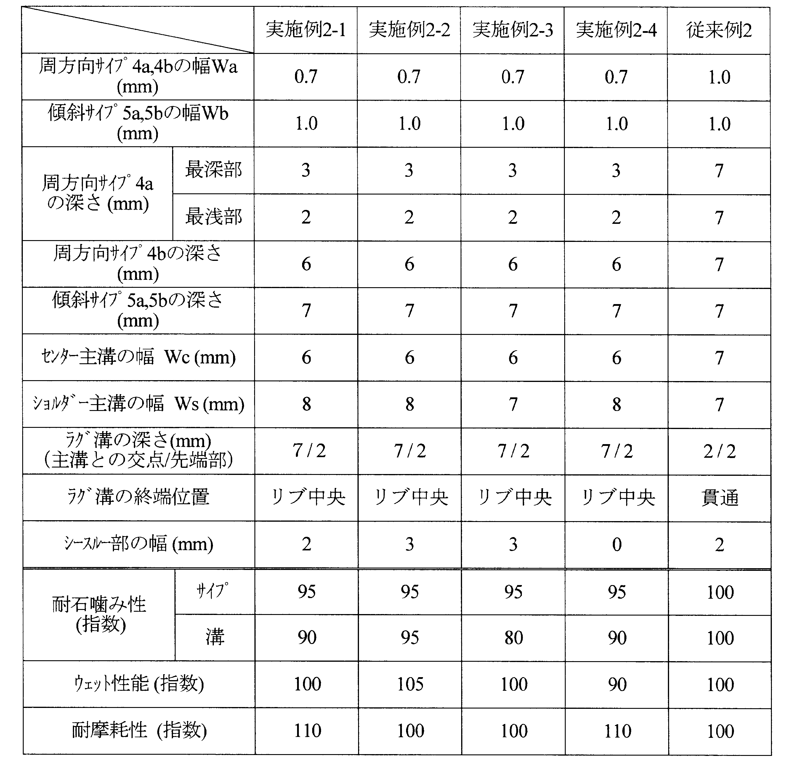
表2より、WcをWsよりも小さくすることで、ウェット性能を悪化させることなく、耐石噛み性が向上していることがわかる。
1 主溝
2 ラグ溝
3 陸部
4 周方向サイプ
5 傾斜サイプ
6 連通部
7 溝
10 トレッド部
11 ビードコア
12 ビード部
13 サイドウォール部
14 カーカスプライ
15 ベルト層
2 ラグ溝
3 陸部
4 周方向サイプ
5 傾斜サイプ
6 連通部
7 溝
10 トレッド部
11 ビードコア
12 ビード部
13 サイドウォール部
14 カーカスプライ
15 ベルト層
Claims (9)
- 環状に形成されたトレッド部の接地領域に、タイヤ周方向に連続して延びる少なくとも3本の主溝により区画された陸部を有する空気入りラジアルタイヤにおいて、
タイヤ幅方向両外側の主溝をショルダー主溝、該ショルダー主溝よりもタイヤ幅方向内側にある主溝をセンター主溝とし、前記ショルダー主溝よりもタイヤ幅方向外側に形成された陸部をショルダー陸部、該ショルダー陸部よりもタイヤ幅方向内側に形成された陸部をセンター陸部としたとき、前記ショルダー陸部および前記センター陸部に、タイヤ周方向に延びる周方向サイプと、タイヤ周方向に対して傾斜して延びる傾斜サイプと、が設けられ、前記周方向サイプの幅Waと、前記傾斜サイプの幅Wbとが、下記式(1)、
Wa<Wb (1)
で表される関係を満足し、かつ、前記周方向サイプが前記傾斜サイプよりも浅いことを特徴とする空気入りラジアルタイヤ。 - 前記センター主溝からタイヤ周方向に対して傾斜して延びる複数本のラグ溝が設けられ、前記ラグ溝が、前記センター陸部のタイヤ幅方向略中央で前記センター陸部に設けられた前記周方向サイプおよび前記傾斜サイプと連通してなり、かつ、前記ラグ溝と前記周方向サイプとの連通部、および前記傾斜サイプとの連通部におけるラグ溝の深さが、前記周方向サイプおよび前記傾斜サイプの深さよりも浅い請求項1記載の空気入りラジアルタイヤ。
- 前記センター陸部に設けられた周方向サイプの深さが、前記ラグ溝間の略中央で最も深い請求項1または2記載の空気入りラジアルタイヤ。
- 前記センター陸部に設けられた周方向サイプの最も深い部分における深さと、前記ショルダー陸部に設けられた周方向サイプの最も深い部分における深さと、が同じである請求項1~3のうちいずれか一項記載の空気入りラジアルタイヤ。
- 前記ショルダー陸部に設けられた周方向サイプが、タイヤ周方向に向かって連続して延びる請求項1~4のうちいずれか一項記載の空気入りラジアルタイヤ。
- 前記センター主溝の幅Wcと、前記ショルダー主溝の幅Wsとが、下記式(2)、
Wc<Ws (2)
で表される関係を満足し、
前記センター陸部が、前記センター主溝からタイヤ周方向に対して傾斜して延びる複数本のラグ溝を有し、該ラグ溝が、前記センター主溝から離れるにつれてタイヤ周方向とのなす角度が小さくなり、かつ、前記ラグ溝の深さが、前記センター主溝から離れるにつれて浅くなる請求項1~5のうちいずれか一項記載の空気入りラジアルタイヤ。 - 前記ラグ溝が、前記センター陸部のタイヤ幅方向略中央で前記センター陸部に設けられた前記周方向サイプおよび前記傾斜サイプと連通してなる請求項6記載の空気入りラジアルタイヤ。
- 前記ラグ溝が前記センター陸部のタイヤ幅方向略中央で終端している請求項6または7記載の空気入りラジアルタイヤ。
- 前記主溝が周方向に幅を有する直線部を有する求項6~8のうちいずれか一項記載の空気入りラジアルタイヤ。
Applications Claiming Priority (4)
| Application Number | Priority Date | Filing Date | Title |
|---|---|---|---|
| JP2013155977A JP5890353B2 (ja) | 2013-07-26 | 2013-07-26 | 空気入りラジアルタイヤ |
| JP2013155978A JP5890354B2 (ja) | 2013-07-26 | 2013-07-26 | 空気入りラジアルタイヤ |
| JP2013-155978 | 2013-07-26 | ||
| JP2013-155977 | 2013-07-26 |
Publications (1)
| Publication Number | Publication Date |
|---|---|
| WO2015012402A1 true WO2015012402A1 (ja) | 2015-01-29 |
Family
ID=52263871
Family Applications (1)
| Application Number | Title | Priority Date | Filing Date |
|---|---|---|---|
| PCT/JP2014/069751 Ceased WO2015012402A1 (ja) | 2013-07-26 | 2014-07-25 | 空気入りラジアルタイヤ |
Country Status (2)
| Country | Link |
|---|---|
| CN (2) | CN204095410U (ja) |
| WO (1) | WO2015012402A1 (ja) |
Cited By (1)
| Publication number | Priority date | Publication date | Assignee | Title |
|---|---|---|---|---|
| CN114734757A (zh) * | 2017-08-30 | 2022-07-12 | 住友橡胶工业株式会社 | 充气子午线轮胎 |
Families Citing this family (5)
| Publication number | Priority date | Publication date | Assignee | Title |
|---|---|---|---|---|
| FI127150B (en) * | 2017-01-18 | 2017-12-15 | Nokian Renkaat Oyj | Pattern block arrangement for pneumatic tire or tread band |
| JP2019111845A (ja) * | 2017-12-20 | 2019-07-11 | 株式会社ブリヂストン | 空気入りタイヤ |
| JP7102893B2 (ja) * | 2018-04-17 | 2022-07-20 | 住友ゴム工業株式会社 | タイヤ |
| CN111323245A (zh) * | 2020-03-13 | 2020-06-23 | 安徽德技汽车检测中心有限公司 | 一种检测轮胎行驶中夹带石子的试验方法 |
| JP7680904B2 (ja) * | 2021-08-04 | 2025-05-21 | 株式会社ブリヂストン | タイヤ |
Citations (9)
| Publication number | Priority date | Publication date | Assignee | Title |
|---|---|---|---|---|
| JPH0253617A (ja) * | 1988-08-15 | 1990-02-22 | Toyo Tire & Rubber Co Ltd | 石咬みを防止した空気入りタイヤ |
| JPH07290909A (ja) * | 1994-04-26 | 1995-11-07 | Bridgestone Corp | 方向性傾斜溝を有する空気入りタイヤ |
| WO2000006398A1 (fr) * | 1998-07-29 | 2000-02-10 | Bridgestone Corporation | Pneumatique |
| JP2006131097A (ja) * | 2004-11-05 | 2006-05-25 | Yokohama Rubber Co Ltd:The | 冬用空気入りタイヤ |
| JP2007182145A (ja) * | 2006-01-06 | 2007-07-19 | Toyo Tire & Rubber Co Ltd | 空気入りタイヤ |
| JP2009078654A (ja) * | 2007-09-26 | 2009-04-16 | Bridgestone Corp | 空気入りタイヤ |
| JP2012056513A (ja) * | 2010-09-10 | 2012-03-22 | Sumitomo Rubber Ind Ltd | 重荷重用タイヤ |
| JP2012076664A (ja) * | 2010-10-05 | 2012-04-19 | Yokohama Rubber Co Ltd:The | 空気入りタイヤ |
| JP2013018450A (ja) * | 2011-07-13 | 2013-01-31 | Bridgestone Corp | 空気入りタイヤ |
-
2014
- 2014-07-25 WO PCT/JP2014/069751 patent/WO2015012402A1/ja not_active Ceased
- 2014-07-28 CN CN201420420931.2U patent/CN204095410U/zh not_active Expired - Fee Related
- 2014-07-28 CN CN201410364775.7A patent/CN104339986B/zh not_active Expired - Fee Related
Patent Citations (9)
| Publication number | Priority date | Publication date | Assignee | Title |
|---|---|---|---|---|
| JPH0253617A (ja) * | 1988-08-15 | 1990-02-22 | Toyo Tire & Rubber Co Ltd | 石咬みを防止した空気入りタイヤ |
| JPH07290909A (ja) * | 1994-04-26 | 1995-11-07 | Bridgestone Corp | 方向性傾斜溝を有する空気入りタイヤ |
| WO2000006398A1 (fr) * | 1998-07-29 | 2000-02-10 | Bridgestone Corporation | Pneumatique |
| JP2006131097A (ja) * | 2004-11-05 | 2006-05-25 | Yokohama Rubber Co Ltd:The | 冬用空気入りタイヤ |
| JP2007182145A (ja) * | 2006-01-06 | 2007-07-19 | Toyo Tire & Rubber Co Ltd | 空気入りタイヤ |
| JP2009078654A (ja) * | 2007-09-26 | 2009-04-16 | Bridgestone Corp | 空気入りタイヤ |
| JP2012056513A (ja) * | 2010-09-10 | 2012-03-22 | Sumitomo Rubber Ind Ltd | 重荷重用タイヤ |
| JP2012076664A (ja) * | 2010-10-05 | 2012-04-19 | Yokohama Rubber Co Ltd:The | 空気入りタイヤ |
| JP2013018450A (ja) * | 2011-07-13 | 2013-01-31 | Bridgestone Corp | 空気入りタイヤ |
Cited By (2)
| Publication number | Priority date | Publication date | Assignee | Title |
|---|---|---|---|---|
| CN114734757A (zh) * | 2017-08-30 | 2022-07-12 | 住友橡胶工业株式会社 | 充气子午线轮胎 |
| CN114734757B (zh) * | 2017-08-30 | 2024-02-06 | 住友橡胶工业株式会社 | 充气子午线轮胎 |
Also Published As
| Publication number | Publication date |
|---|---|
| CN204095410U (zh) | 2015-01-14 |
| CN104339986A (zh) | 2015-02-11 |
| CN104339986B (zh) | 2017-10-10 |
Similar Documents
| Publication | Publication Date | Title |
|---|---|---|
| JP6652507B2 (ja) | 空気入りタイヤ | |
| JP5452388B2 (ja) | 空気入りタイヤ | |
| JP4516342B2 (ja) | 重荷重用タイヤ | |
| JPWO2014091789A1 (ja) | 空気入りタイヤ | |
| JP2016150603A (ja) | 空気入りタイヤ | |
| US10994574B2 (en) | Pneumatic tire | |
| US11724549B2 (en) | Pneumatic tire | |
| JP2014213639A (ja) | 空気入りタイヤ | |
| US8517071B2 (en) | Pneumatic tire | |
| JP5403077B2 (ja) | 空気入りタイヤ | |
| JPWO2019171554A1 (ja) | 空気入りタイヤ | |
| JP2016112926A (ja) | 空気入りタイヤ | |
| JP2020108989A (ja) | 空気入りタイヤ | |
| JP5109823B2 (ja) | 空気入りタイヤ | |
| EP3845397B1 (en) | Pneumatic tire | |
| JP5109481B2 (ja) | 重荷重用空気入りタイヤ | |
| JP5890354B2 (ja) | 空気入りラジアルタイヤ | |
| JP5890353B2 (ja) | 空気入りラジアルタイヤ | |
| US20220258543A1 (en) | Pneumatic tire | |
| US20200298627A1 (en) | Pneumatic tire | |
| WO2017043227A1 (ja) | 空気入りタイヤ | |
| JP6848413B2 (ja) | 空気入りタイヤ | |
| JP2017140858A (ja) | 空気入りタイヤ | |
| JP2010120479A (ja) | 空気入りタイヤ | |
| CN113453914A (zh) | 充气轮胎 |
Legal Events
| Date | Code | Title | Description |
|---|---|---|---|
| 121 | Ep: the epo has been informed by wipo that ep was designated in this application |
Ref document number: 14830048 Country of ref document: EP Kind code of ref document: A1 |
|
| NENP | Non-entry into the national phase |
Ref country code: DE |
|
| 122 | Ep: pct application non-entry in european phase |
Ref document number: 14830048 Country of ref document: EP Kind code of ref document: A1 |