WO2015015618A1 - Procédé de production de récipient en résine synthétique, et récipient en résine synthétique - Google Patents
Procédé de production de récipient en résine synthétique, et récipient en résine synthétique Download PDFInfo
- Publication number
- WO2015015618A1 WO2015015618A1 PCT/JP2013/070891 JP2013070891W WO2015015618A1 WO 2015015618 A1 WO2015015618 A1 WO 2015015618A1 JP 2013070891 W JP2013070891 W JP 2013070891W WO 2015015618 A1 WO2015015618 A1 WO 2015015618A1
- Authority
- WO
- WIPO (PCT)
- Prior art keywords
- synthetic resin
- resin container
- insert
- parison
- base
- Prior art date
- Legal status (The legal status is an assumption and is not a legal conclusion. Google has not performed a legal analysis and makes no representation as to the accuracy of the status listed.)
- Ceased
Links
Images







Classifications
-
- B—PERFORMING OPERATIONS; TRANSPORTING
- B29—WORKING OF PLASTICS; WORKING OF SUBSTANCES IN A PLASTIC STATE IN GENERAL
- B29C—SHAPING OR JOINING OF PLASTICS; SHAPING OF MATERIAL IN A PLASTIC STATE, NOT OTHERWISE PROVIDED FOR; AFTER-TREATMENT OF THE SHAPED PRODUCTS, e.g. REPAIRING
- B29C49/00—Blow-moulding, i.e. blowing a preform or parison to a desired shape within a mould; Apparatus therefor
- B29C49/20—Blow-moulding, i.e. blowing a preform or parison to a desired shape within a mould; Apparatus therefor of articles having inserts or reinforcements ; Handling of inserts or reinforcements
-
- B—PERFORMING OPERATIONS; TRANSPORTING
- B29—WORKING OF PLASTICS; WORKING OF SUBSTANCES IN A PLASTIC STATE IN GENERAL
- B29D—PRODUCING PARTICULAR ARTICLES FROM PLASTICS OR FROM SUBSTANCES IN A PLASTIC STATE
- B29D22/00—Producing hollow articles
- B29D22/003—Containers for packaging, storing or transporting, e.g. bottles, jars, cans, barrels, tanks
-
- B—PERFORMING OPERATIONS; TRANSPORTING
- B65—CONVEYING; PACKING; STORING; HANDLING THIN OR FILAMENTARY MATERIAL
- B65D—CONTAINERS FOR STORAGE OR TRANSPORT OF ARTICLES OR MATERIALS, e.g. BAGS, BARRELS, BOTTLES, BOXES, CANS, CARTONS, CRATES, DRUMS, JARS, TANKS, HOPPERS, FORWARDING CONTAINERS; ACCESSORIES, CLOSURES, OR FITTINGS THEREFOR; PACKAGING ELEMENTS; PACKAGES
- B65D1/00—Rigid or semi-rigid containers having bodies formed in one piece, e.g. by casting metallic material, by moulding plastics, by blowing vitreous material, by throwing ceramic material, by moulding pulped fibrous material or by deep-drawing operations performed on sheet material
- B65D1/12—Cans, casks, barrels, or drums
- B65D1/14—Cans, casks, barrels, or drums characterised by shape
- B65D1/18—Cans, casks, barrels, or drums characterised by shape of polygonal cross-section
-
- B—PERFORMING OPERATIONS; TRANSPORTING
- B65—CONVEYING; PACKING; STORING; HANDLING THIN OR FILAMENTARY MATERIAL
- B65D—CONTAINERS FOR STORAGE OR TRANSPORT OF ARTICLES OR MATERIALS, e.g. BAGS, BARRELS, BOTTLES, BOXES, CANS, CARTONS, CRATES, DRUMS, JARS, TANKS, HOPPERS, FORWARDING CONTAINERS; ACCESSORIES, CLOSURES, OR FITTINGS THEREFOR; PACKAGING ELEMENTS; PACKAGES
- B65D25/00—Details of other kinds or types of rigid or semi-rigid containers
- B65D25/28—Handles
- B65D25/2882—Integral handles
- B65D25/2894—Integral handles provided on the top or upper wall
-
- B—PERFORMING OPERATIONS; TRANSPORTING
- B65—CONVEYING; PACKING; STORING; HANDLING THIN OR FILAMENTARY MATERIAL
- B65D—CONTAINERS FOR STORAGE OR TRANSPORT OF ARTICLES OR MATERIALS, e.g. BAGS, BARRELS, BOTTLES, BOXES, CANS, CARTONS, CRATES, DRUMS, JARS, TANKS, HOPPERS, FORWARDING CONTAINERS; ACCESSORIES, CLOSURES, OR FITTINGS THEREFOR; PACKAGING ELEMENTS; PACKAGES
- B65D25/00—Details of other kinds or types of rigid or semi-rigid containers
- B65D25/28—Handles
- B65D25/2882—Integral handles
- B65D25/2897—Integral handles formed in the wall(s), e.g. roughenings, cavities or projections
-
- B—PERFORMING OPERATIONS; TRANSPORTING
- B65—CONVEYING; PACKING; STORING; HANDLING THIN OR FILAMENTARY MATERIAL
- B65D—CONTAINERS FOR STORAGE OR TRANSPORT OF ARTICLES OR MATERIALS, e.g. BAGS, BARRELS, BOTTLES, BOXES, CANS, CARTONS, CRATES, DRUMS, JARS, TANKS, HOPPERS, FORWARDING CONTAINERS; ACCESSORIES, CLOSURES, OR FITTINGS THEREFOR; PACKAGING ELEMENTS; PACKAGES
- B65D25/00—Details of other kinds or types of rigid or semi-rigid containers
- B65D25/28—Handles
- B65D25/30—Hand holes
-
- B—PERFORMING OPERATIONS; TRANSPORTING
- B65—CONVEYING; PACKING; STORING; HANDLING THIN OR FILAMENTARY MATERIAL
- B65D—CONTAINERS FOR STORAGE OR TRANSPORT OF ARTICLES OR MATERIALS, e.g. BAGS, BARRELS, BOTTLES, BOXES, CANS, CARTONS, CRATES, DRUMS, JARS, TANKS, HOPPERS, FORWARDING CONTAINERS; ACCESSORIES, CLOSURES, OR FITTINGS THEREFOR; PACKAGING ELEMENTS; PACKAGES
- B65D25/00—Details of other kinds or types of rigid or semi-rigid containers
- B65D25/38—Devices for discharging contents
- B65D25/40—Nozzles or spouts
-
- B—PERFORMING OPERATIONS; TRANSPORTING
- B65—CONVEYING; PACKING; STORING; HANDLING THIN OR FILAMENTARY MATERIAL
- B65D—CONTAINERS FOR STORAGE OR TRANSPORT OF ARTICLES OR MATERIALS, e.g. BAGS, BARRELS, BOTTLES, BOXES, CANS, CARTONS, CRATES, DRUMS, JARS, TANKS, HOPPERS, FORWARDING CONTAINERS; ACCESSORIES, CLOSURES, OR FITTINGS THEREFOR; PACKAGING ELEMENTS; PACKAGES
- B65D25/00—Details of other kinds or types of rigid or semi-rigid containers
- B65D25/38—Devices for discharging contents
- B65D25/40—Nozzles or spouts
- B65D25/48—Separable nozzles or spouts
-
- B—PERFORMING OPERATIONS; TRANSPORTING
- B29—WORKING OF PLASTICS; WORKING OF SUBSTANCES IN A PLASTIC STATE IN GENERAL
- B29C—SHAPING OR JOINING OF PLASTICS; SHAPING OF MATERIAL IN A PLASTIC STATE, NOT OTHERWISE PROVIDED FOR; AFTER-TREATMENT OF THE SHAPED PRODUCTS, e.g. REPAIRING
- B29C49/00—Blow-moulding, i.e. blowing a preform or parison to a desired shape within a mould; Apparatus therefor
- B29C49/20—Blow-moulding, i.e. blowing a preform or parison to a desired shape within a mould; Apparatus therefor of articles having inserts or reinforcements ; Handling of inserts or reinforcements
- B29C2049/2017—Blow-moulding, i.e. blowing a preform or parison to a desired shape within a mould; Apparatus therefor of articles having inserts or reinforcements ; Handling of inserts or reinforcements outside the article
-
- B—PERFORMING OPERATIONS; TRANSPORTING
- B29—WORKING OF PLASTICS; WORKING OF SUBSTANCES IN A PLASTIC STATE IN GENERAL
- B29C—SHAPING OR JOINING OF PLASTICS; SHAPING OF MATERIAL IN A PLASTIC STATE, NOT OTHERWISE PROVIDED FOR; AFTER-TREATMENT OF THE SHAPED PRODUCTS, e.g. REPAIRING
- B29C49/00—Blow-moulding, i.e. blowing a preform or parison to a desired shape within a mould; Apparatus therefor
- B29C49/20—Blow-moulding, i.e. blowing a preform or parison to a desired shape within a mould; Apparatus therefor of articles having inserts or reinforcements ; Handling of inserts or reinforcements
- B29C2049/2021—Inserts characterised by the material or type
- B29C2049/2034—Attachments, e.g. hooks to hold or hang the blown article
- B29C2049/2039—Handles, e.g. handles or grips on bottles
-
- B—PERFORMING OPERATIONS; TRANSPORTING
- B29—WORKING OF PLASTICS; WORKING OF SUBSTANCES IN A PLASTIC STATE IN GENERAL
- B29C—SHAPING OR JOINING OF PLASTICS; SHAPING OF MATERIAL IN A PLASTIC STATE, NOT OTHERWISE PROVIDED FOR; AFTER-TREATMENT OF THE SHAPED PRODUCTS, e.g. REPAIRING
- B29C49/00—Blow-moulding, i.e. blowing a preform or parison to a desired shape within a mould; Apparatus therefor
- B29C49/20—Blow-moulding, i.e. blowing a preform or parison to a desired shape within a mould; Apparatus therefor of articles having inserts or reinforcements ; Handling of inserts or reinforcements
- B29C2049/2021—Inserts characterised by the material or type
- B29C2049/2043—Inserts characterised by the material or type comprising threads, e.g. screws or nuts
-
- B—PERFORMING OPERATIONS; TRANSPORTING
- B29—WORKING OF PLASTICS; WORKING OF SUBSTANCES IN A PLASTIC STATE IN GENERAL
- B29C—SHAPING OR JOINING OF PLASTICS; SHAPING OF MATERIAL IN A PLASTIC STATE, NOT OTHERWISE PROVIDED FOR; AFTER-TREATMENT OF THE SHAPED PRODUCTS, e.g. REPAIRING
- B29C49/00—Blow-moulding, i.e. blowing a preform or parison to a desired shape within a mould; Apparatus therefor
- B29C49/20—Blow-moulding, i.e. blowing a preform or parison to a desired shape within a mould; Apparatus therefor of articles having inserts or reinforcements ; Handling of inserts or reinforcements
- B29C2049/2073—Means for feeding the inserts into the mould, preform or parison, e.g. grippers
-
- B—PERFORMING OPERATIONS; TRANSPORTING
- B29—WORKING OF PLASTICS; WORKING OF SUBSTANCES IN A PLASTIC STATE IN GENERAL
- B29K—INDEXING SCHEME ASSOCIATED WITH SUBCLASSES B29B, B29C OR B29D, RELATING TO MOULDING MATERIALS OR TO MATERIALS FOR MOULDS, REINFORCEMENTS, FILLERS OR PREFORMED PARTS, e.g. INSERTS
- B29K2023/00—Use of polyalkenes or derivatives thereof as moulding material
- B29K2023/04—Polymers of ethylene
- B29K2023/06—PE, i.e. polyethylene
-
- B—PERFORMING OPERATIONS; TRANSPORTING
- B29—WORKING OF PLASTICS; WORKING OF SUBSTANCES IN A PLASTIC STATE IN GENERAL
- B29K—INDEXING SCHEME ASSOCIATED WITH SUBCLASSES B29B, B29C OR B29D, RELATING TO MOULDING MATERIALS OR TO MATERIALS FOR MOULDS, REINFORCEMENTS, FILLERS OR PREFORMED PARTS, e.g. INSERTS
- B29K2105/00—Condition, form or state of moulded material or of the material to be shaped
- B29K2105/25—Solid
- B29K2105/253—Preform
-
- B—PERFORMING OPERATIONS; TRANSPORTING
- B29—WORKING OF PLASTICS; WORKING OF SUBSTANCES IN A PLASTIC STATE IN GENERAL
- B29K—INDEXING SCHEME ASSOCIATED WITH SUBCLASSES B29B, B29C OR B29D, RELATING TO MOULDING MATERIALS OR TO MATERIALS FOR MOULDS, REINFORCEMENTS, FILLERS OR PREFORMED PARTS, e.g. INSERTS
- B29K2623/00—Use of polyalkenes or derivatives thereof for preformed parts, e.g. for inserts
- B29K2623/04—Polymers of ethylene
- B29K2623/06—PE, i.e. polyethylene
-
- B—PERFORMING OPERATIONS; TRANSPORTING
- B29—WORKING OF PLASTICS; WORKING OF SUBSTANCES IN A PLASTIC STATE IN GENERAL
- B29L—INDEXING SCHEME ASSOCIATED WITH SUBCLASS B29C, RELATING TO PARTICULAR ARTICLES
- B29L2031/00—Other particular articles
- B29L2031/712—Containers; Packaging elements or accessories, Packages
-
- B—PERFORMING OPERATIONS; TRANSPORTING
- B29—WORKING OF PLASTICS; WORKING OF SUBSTANCES IN A PLASTIC STATE IN GENERAL
- B29L—INDEXING SCHEME ASSOCIATED WITH SUBCLASS B29C, RELATING TO PARTICULAR ARTICLES
- B29L2031/00—Other particular articles
- B29L2031/712—Containers; Packaging elements or accessories, Packages
- B29L2031/7172—Fuel tanks, jerry cans
Definitions
- the present invention relates to a synthetic resin container manufacturing method and a synthetic resin container.
- Patent Document 1 and Patent Document 2 a container made of synthetic resin having a rectangular parallelepiped shape, having a base at least at one end of the top surface, and having three handles juxtaposed along the long side of the top surface. It is disclosed. When two containers are adjacent to each other so that their handles are parallel to each other, the outermost handles of each container are close to each other, so that both of these handles can be gripped simultaneously. That is, by placing fingers on both handles and carrying two containers simultaneously with one hand, a maximum of four containers can be carried with both hands.
- the handles arranged on both sides of the container top surface are held by two persons from both sides of the container, and two persons cooperate to hold one container. It can also be carried around.
- Patent Document 1 and Patent Document 2 do not disclose the above-described container manufacturing method
- Patent Document 3 is conventionally known as a container manufacturing method having one handle.
- Patent Document 3 a parison is supplied into a pair of molds having a cavity for molding a container main body including a base and a cavity for molding a handle part, and the parison is clamped after the pair of molds are clamped.
- a manufacturing method for manufacturing a container by blowing is disclosed. That is, a method is disclosed in which the container body portion and the handle portion are simultaneously molded by a single mold by blow molding.
- the parison in the mold is blown to form the container body and the handle at the same time with one mold, then the pair of molds are opened, and the molded product is separated from the mold.
- Shape and manufacture the container In order to release the handle part of the container from the mold, if the handle part is not arranged on the die mating surfaces (part surfaces) of the pair of molds, the handle part is released from the opened mold. I can't shape it. Therefore, in the manufacturing method of Patent Document 3, it is inevitably possible to manufacture only a container having one handle. That is, the containers of Patent Documents 1 and 2 cannot be manufactured by the manufacturing method of Patent Document 3.
- the base part of the container is also formed at the same time as the container main body part and the handle part.
- a screw cap for sealing the inside of the container is attached to the base, it is necessary to form a male screw that is screwed with the screw cap over the entire circumference of the base.
- the present invention has been made in view of such points, and an object of the present invention is to provide a synthetic resin container having a plurality of handles on the top surface and a method for manufacturing the same.
- the present invention is configured as follows.
- the synthetic resin container manufacturing method is a synthetic resin container manufacturing method for manufacturing, by blow molding, a synthetic resin container having a base on at least one end of the top surface and a plurality of handles juxtaposed on the top surface. Then, the base and the plurality of handles are formed in advance as insert parts, respectively, and an insert part heating step of heating the fusion part of the insert parts at a fusion temperature of these insert parts, and after the insert part heating step
- a container forming step of fusing the serial insert part characterized in that it comprises a.
- the insert parts are individually molded in advance, the insert parts can be molded by a molding method in which the parting line is not conspicuous, unlike the prior art.
- the screw cap which seals a nozzle
- the adhesiveness between the base and the screw cap is high, the packing conventionally used to supplement the adhesiveness can be eliminated.
- an auxiliary handle is further formed in advance as the insert part, and the auxiliary handle is positioned at the bottom of the synthetic resin container and at a position diagonal to the position of the base. It is set as the structure to arrange.
- a gripping concave portion into which a finger fits is formed in either or either of the handle and the auxiliary handle in the insert part.
- the synthetic resin container according to the present invention is manufactured by the above synthetic resin container manufacturing method.
- the synthetic resin container according to the present invention is characterized in that a plurality of handles are fused to the top surface of the container body formed by blow molding and having a base on the top surface.
- an auxiliary handle is provided on the bottom surface of the container body and at a position diagonal to the position of the base.
- two containers can cooperate to carry one container.
- two synthetic resin containers of this invention are mutually parallel. If they are adjacent to each other, the outermost handles of the containers are close to each other, so that both of these handles can be held simultaneously. That is, by placing fingers on both handles and carrying two containers simultaneously with one hand, a maximum of four containers can be carried with both hands.
- the handles arranged on both sides of the top surface of the container can be gripped by two persons from both sides of the container.
- a synthetic resin container having a plurality of handles on the top surface and a method for manufacturing the same can be provided.
- FIG. It is a figure which shows the insert component used for manufacture of the synthetic resin container of this invention, Comprising: (a) is a perspective view of a nozzle
- FIG. It is a figure which shows the 1st component holder used for manufacture of the synthetic resin container of this invention, Comprising: (a) is a perspective view of a 1st component holder, (b) is a bottom view of (a).
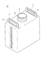
- FIG. 1A is a perspective view of a synthetic resin container according to the present invention
- FIG. 1B is a perspective view of a modified example of the synthetic resin container according to the present invention
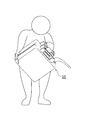
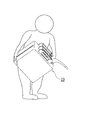
- FIGS. 2A to 3B show usage modes of the synthetic resin container of the present invention.
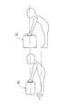
- FIG. 4 is an explanatory diagram for explaining the operational effects of the synthetic resin container shown in FIG. 1B.
- the synthetic resin container 10 is substantially rectangular, has a base 2 at least at one end of the top surface, and has three handles 3 juxtaposed along the longitudinal direction of the top surface.
- auxiliary handles 4 are provided at the base 2 and diagonal positions (see FIG. 1A).
- a gripping recess 31 into which a finger is fitted is formed on the side surface of each handle 3 arranged on the top surface, and through holes 33 (FIG. 5 described later) are formed at both ends in the longitudinal direction of each handle 3. (B) is formed.
- a gripping member 32 that connects each handle 3 is inserted into each through-hole 33, and each handle 3 is connected by the gripping member 32.
- a male screw 21 that is screwed with a screw cap (not shown) that seals the inside of the synthetic resin container 10 is formed over the entire circumference of the base 2 disposed at one end of the top surface.
- the auxiliary handle 4 disposed on the bottom surface is formed with a holding recess 41 into which a finger can be fitted.
- the corner portion of the synthetic resin container 10 provided with the auxiliary handle 4 is formed on a slope, and the width dimension of the auxiliary handle 4 is set shorter than the width dimension of the bottom surface of the synthetic resin container 10,
- gaps 50 are formed on both sides of the auxiliary handle 4. Therefore, when the synthetic resin container 10 is placed on the ground, the synthetic resin container 10 can be easily grasped by inserting a hand into the gap 50.
- the base 2 is formed at the center of the top surface, and the handle 3 is formed on the top surface along the short side direction of the top surface. It is good also as the synthetic resin container 10 formed in both ends.
- the synthetic resin container 10 is not provided with the auxiliary handle 4 described above, but the auxiliary handle 4 may be provided.
- the synthetic resin container 10 according to the present invention shown in FIG. 1A has three handles 3 arranged in parallel along the longitudinal direction of the top surface. If the two synthetic resin containers 10 are adjacent to each other so that the handles 3 are parallel to each other, the outermost handles 3 of the synthetic resin containers 10 are close to each other. It can be gripped. That is, two synthetic resin containers 10 can be carried simultaneously with one hand by putting fingers on both handles 3 and a maximum of four synthetic resin containers 10 can be carried with both hands (see FIG. 2A).
- the synthetic resin container 10 according to the present invention is provided with the auxiliary handle 4 on the bottom surface and at the diagonal position with respect to the base 2 position, the contents accommodated in the synthetic resin container 10 are discharged from the base 2. In doing so, by holding the handle 3 and holding the auxiliary handle 4 and tilting the synthetic resin container 10, the contents can be easily discharged from the base 2 (see FIG. 3A). Furthermore, it is possible to grasp both the gripping member 32 connecting each handle 3 and the auxiliary handle 4 and discharge the contents from the base 2 (see FIG. 3B).
- the number of the top handles 3 of the synthetic resin container 10 is not limited to three, and may be two or four or more.
- the handle 3 is arranged along the short direction, so that the user can see in FIG. 1A as shown in FIG. Hold both handles 3 in a state where the body is closer to the center of gravity of the synthetic resin container 10 than the synthetic resin container 10 (in FIG. 4, the center of gravity of the synthetic resin container 10 can be approached by a distance L).
- the synthetic resin container 10 can be carried around. 1B, when the synthetic resin container 10 shown in FIG. 1B is lifted, the synthetic resin container 10 does not have to bend forward as compared with the case where the synthetic resin container 10 shown in FIG. 1A is lifted. Can be lifted.
- the synthetic resin container manufacturing method according to the present embodiment is a synthetic resin container manufacturing method for manufacturing a synthetic resin container by blow molding, and includes an insert component heating step, an insert component placement step, and a container molding step. It is characterized by.
- FIG. 5 is a view showing an insert part used for manufacturing the synthetic resin container of the present invention, in which (a) is a perspective view of a cap part, (b) is a perspective view of a handle part, and (c) is a perspective view. It is a perspective view of an auxiliary handle part.
- FIG. 6 is a view showing a first component holder used for manufacturing the synthetic resin container of the present invention, wherein (a) is a perspective view of the first component holder, and (b) is a bottom surface of (a).
- FIG. 7 is a view showing an example of a first component holder used in the production of the synthetic resin container of the present invention shown in FIG. 1B, wherein (a) is a perspective view of the first component holder, and (b) is a perspective view of the first component holder. It is a bottom view of (a).
- FIG. 8 is a perspective view of a second component holder used for manufacturing the synthetic resin container of the present invention.
- the insert component heating step is a step of heating a pre-molded insert component at the fusion temperature of the insert component.
- the insert parts of this embodiment correspond to a base part 20 corresponding to the base 2 of the synthetic resin container 10, a handle part 30 corresponding to the handle 3 of the synthetic resin container 10, and an auxiliary handle 4 of the synthetic resin container 10.
- Auxiliary handle parts 40 are used, both of which are made of polyethylene.
- the base part 20 is a cylindrical member having a male screw 21 formed on the outer peripheral surface, and a flange-shaped fusion surface 24 that is fused to a parison P described later is provided at the lower end thereof (FIG. 5). (See (a)).
- the grip part 30 is formed with a gripping recess 31 on the side surface of which the finger fits (see FIG. 5B). At both ends of the handle part 30 in the longitudinal direction, through holes 33 are formed through which the gripping member 32 (see FIG. 1A) is inserted.
- the bottom surface of the handle part 30 is a fusion surface 34 to be fused with a parison P described later.
- the auxiliary handle part 40 includes a substantially rectangular flat plate auxiliary handle body 42, and holding members 43 that are provided on both sides of the auxiliary handle body 42 and hold the auxiliary handle body 42 perpendicular to the bottom surface of the synthetic resin container 10. (See FIG. 5C).
- the auxiliary handle main body 42 is formed with a holding recess 41 into which a finger is fitted along the longitudinal direction.
- the holding member 43 is fitted to the second holding base 222 of the second component holder 212 described later. And let the upper surface of the auxiliary handle main body 42 and the inclined surface of the holding member 43 be a fusion surface 44 to be fused with a parison P described later.
- insert parts are individually molded in advance by a known resin molding method in which the parting line is not noticeable.
- the base part 20 has a parting line that is not conspicuous, and a male screw 21 having a specified shape can be easily formed on the outer peripheral surface thereof.
- each insert part is attached to the component holder.
- the component holder is accommodated in molds 310 and 320 (to be described later) together with the insert component while holding the insert component.
- the component holder of the present embodiment includes a first component holder 211 that holds insert components (a cap part 20 and a handle part 30) provided on the top surface of the synthetic resin container 10 and a bottom surface of the synthetic resin container 10. And a second part holder 212 for holding the insert part (auxiliary handle part 40) to be used.
- a first component holder 211 that holds insert components (a cap part 20 and a handle part 30) provided on the top surface of the synthetic resin container 10 and a bottom surface of the synthetic resin container 10.
- a second part holder 212 for holding the insert part (auxiliary handle part 40) to be used.
- only the 1st component holder 211 may be sufficient.
- the first component holder 211 includes a first holding base 221 that holds an insert part, a support leg 241 that supports the first holding base 221, and a first support leg 241 that is placed on the molds 310 and 320. It is comprised from the one mold mounting base 231 (refer Fig.6 (a)).
- the first holding table 221 is formed with holding grooves 251 for holding a plurality of handle parts 30 side by side along the longitudinal direction, and a holding cylinder 252 for holding the base part 20 is formed at one end.
- the height of the holding cylinder 252 is the same as the height of a support leg 241 described later.
- the opening diameter of the holding cylinder 252 is substantially the same as the outer diameter of the base part 20.
- the support legs 241 support the four corners of the first holding base 221 and are erected from the first mold mounting base 231.
- the height of the support leg 241 is designed to be lower than the height of the handle part 30 held in the holding groove 251 of the first holding base 221.
- the first mold mounting base 231 is a substantially rectangular flat plate having an area larger than the area of the first holding base 221 described above, and both ends of the long sides thereof are a pair of molds 310 and 320 described later. It is accommodated in each of the first accommodation grooves 330.
- An insertion hole 260 for attaching an air supply pipe 22 to be described later is formed at a position where the holding cylinder 252 abuts on the first mold mounting base 231 (see FIG. 6B).
- the 1st holding stand 221 shown to FIG. 7 (a) and FIG.7 (b) is used. That is, the holding cylinder 252 is formed at the center of the first holding table 221, and the holding grooves 251 are formed at both ends of the first holding table 221 along the short direction.
- the second component holder 212 includes a second holding base 222 and a second mold mounting base 232 (see FIG. 8).
- the second mold mounting base 232 is a substantially rectangular flat plate, and both ends of the short sides thereof are respectively accommodated in second accommodation grooves 340 of a pair of molds 310 and 320 described later.
- the second holding base 222 has a substantially right triangular prism shape, and is designed to be shorter than the long side of the auxiliary handle main body 42, so that the auxiliary handle main body 42 can be fitted, and the auxiliary handle part 40 is attached to the synthetic resin container 10. It is held perpendicular to the bottom surface.
- the insert parts (the base part 20, the handle part 30, and the auxiliary handle part 40) are attached to the first part holder 211 and the second part holder 212 described above.
- the base part 20 is inserted into the holding cylinder 252 of the first holding base 221 from the upper surface side of the base part 20, and the plurality of handle parts 30 are first held from the upper surface side of the handle part 30.
- Each is inserted into the holding groove 251 of the base 221. Since the height of the support leg 241 of the first holding base 221 is set lower than the height of the handle part 30, the fusion surface 34 of the handle part 30 can be held out of the first holding base 221. . Further, since the flange portion of the base part 20 comes into contact with the first holding base 221, the fusion surface 24 can also be held out of the first holding base 221 for the base part 20.
- the auxiliary handle part 40 is fitted to the second holding base 222. Thereby, the auxiliary handle part 40 can be held so that the auxiliary handle body 42 is perpendicular to the bottom surface of the synthetic resin container 10.
- each insert part is attached to the first part holder 211 and the second part holder 212, the fusion surfaces 24, 34, and 44 of each insert part are placed on a hot plate and heated. Since the insert part of this embodiment is made of polyethylene, the heating temperature is set to 160 ° C. to 180 ° C., and the fusion surfaces 24, 34, and 44 of each insert part are melted by about 3 mm to 4 mm. Thereby, when the parison P and the fusion surfaces 24, 34, 44 are brought into contact with each other in the container forming step described later, the parison P and the fusion surfaces 24, 34, 44 can be fused.
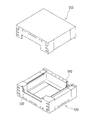
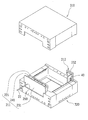
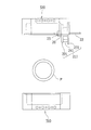
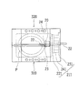
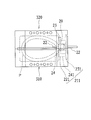
- FIG. 9 is a perspective view of a mold used in the production of the synthetic resin container of the present invention
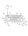
- FIG. 10A is a schematic diagram showing an insert component placement step of the synthetic resin container of the present invention
- FIG. 10B is a synthetic resin of the present invention.
- FIG. 10C is an explanatory diagram for explaining the process of inserting the air supply pipe into the cap part in the insert part placement process of the container
- FIG. 10C shows the insert part placement process seen from the side of the mold in the manufacturing process of the synthetic resin container of the present invention. It is a schematic diagram shown.
- the insert part placement process is performed after the insert part heating process, and is a process of placing the insert parts (the cap part 20, the handle part 30, and the auxiliary handle part 40) in the molds 310 and 320 in parallel with the supply direction of the parison P. is there.
- the first component holder 211 and the second component holder 212 that have been subjected to the insert component heating step are stored in the molds 310 and 320 in parallel with the parison P supply direction.
- the parison supply device (not shown) for supplying the parison P is disposed above the molds 310 and 320, and the parison P can be suspended vertically from the parison supply device.
- the molds 310 and 320 are composed of a pair of opposed split molds, and can be opened and clamped based on the parison supply device (see FIG. 9). Inside the molds 310 and 320, a cavity that matches the shape of the synthetic resin container 10 is provided. In addition, a first accommodation groove 330 that accommodates the first component holder 211 is formed in one of the mold matching surfaces that are parallel to the supply direction of the parison P and in which the molds 310 and 320 are mated. . The length of the first accommodation groove 330 is designed to be the length of the long side of the first mold mounting base 231 described above.
- a second receiving groove 340 for receiving the second component holder 212 is formed at a position facing the surface where the first component holder 211 is stored and at a position opposite to the position where the base component 20 is disposed.
- the length of the second receiving groove 340 is designed to be the length of the short side of the second mold mounting base 232 described above.
- the close contact member 23 prevents the parison P from entering the opening of the base part 20 when the parison P, which will be described later, is blown and expanded. For this reason, the outer diameter of the contact member 23 is the same as the opening diameter of the base part 20, and the contact member 23 is in close contact with the opening of the base part 20. At the center of the contact member 23, an air supply pipe 22 having a smaller diameter than the diameter of the contact member 23 is inserted and fixed.
- the air supply pipe 22 supplies air to the parison P from the outside.
- the tip of the air supply pipe 22 is sharpened to such an extent that it can break through the parison P.
- the close contact member 23 is inserted into the opening of the base part 20, when the air supply pipe 22 inserted into the close contact member 23 is slid with reference to the first component holder 211, the close contact member The base part 20 in close contact with the base 23 slides in the molds 310 and 320 (see FIG. 10C).
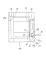
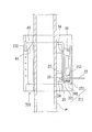
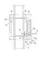
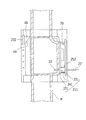
- FIG. 11A to FIG. 11A to FIG. 15 are schematic views showing a container molding step in the method for producing a synthetic resin container of the present invention.
- the container molding process is performed after the insert part placement process described above. After the parison P is supplied into the molds 310 and 320 and the molds 310 and 320 are clamped, the parison P is blown to insert the parison P and the insert parts. Is a step of fusing the two.
- the parison P is suspended from above the molds 310 and 320 opened by the parison supply device to supply the parison P into the cavities of the molds 310 and 320 (see FIGS. 11A and 11B).
- the air supply pipe 22 is slid to bring the base part 20 close to the parison P in advance. That is, the base part 20 is moved in a direction away from the first part holder 211.
- the handle part 30 may be brought close to the parison P in advance (that is, the handle part 30 may be moved away from the first part holder 211).
- the parison P is sandwiched between the pair of molds 310 and 320 and the mold is clamped.
- the air supply pipe 22 is further slid to break through the parison P at the tip of the air supply pipe 22 (see FIGS. 12A and 12B).
- the base part 20 and the contact member 23 come into contact with the parison P.
- the parison P on the side where the base part 20 and the handle part 30 are arranged is inflated, the parison P on the side where the auxiliary handle is arranged is inflated, and the auxiliary handle part 40 held by the second part holder 212 is Parison P contacts. Since the handle part 30, the auxiliary handle part 40, and the base part 20 are respectively melted in the fusing surfaces 24, 34, and 44 by the insert part heating process, the handle part 30, the auxiliary handle part 40, and the base part 20 are parisons. It is fused and integrated with P. At the same time, the parison P is formed into a shape along the cavity shape in the molds 310 and 320 (see FIGS. 14A and 14B).
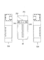
- the molds 310 and 320 are opened (see FIG. 15), and the molded product is released from the molds 310 and 320. Thereafter, the first component holder 211 and the second component holder 212 are removed from the molded product. Thereafter, the gripping member 32 that connects the handles 3 is inserted into the through hole 33 of each handle 3, and the gripping member 32 and the handle 3 are fused. Thereby, the synthetic resin container 10 provided with the some handle 3 on the top
- the above-described insert component heating step insert
- the component placement process and the container forming process can be performed in series. That is, by preparing at least two sets of the first component holder 211 and the second component holder 212, the first component holder 211 and the second component holder 212 of the first set are molds 310 and 320. Since the insert component heating process can be performed on the first component holder 211 and the second component holder 212 of the second set while being placed in the blow molding process, the synthetic resin container 10 can be efficiently used. Can be manufactured.
- the present invention is applicable to a synthetic resin container having a plurality of handles on the top surface and a manufacturing method thereof.
Landscapes
- Engineering & Computer Science (AREA)
- Mechanical Engineering (AREA)
- Manufacturing & Machinery (AREA)
- Ceramic Engineering (AREA)
- Details Of Rigid Or Semi-Rigid Containers (AREA)
- Blow-Moulding Or Thermoforming Of Plastics Or The Like (AREA)
- Containers Having Bodies Formed In One Piece (AREA)
Abstract
Priority Applications (5)
| Application Number | Priority Date | Filing Date | Title |
|---|---|---|---|
| PCT/JP2013/070891 WO2015015618A1 (fr) | 2013-08-01 | 2013-08-01 | Procédé de production de récipient en résine synthétique, et récipient en résine synthétique |
| JP2014509397A JP5734510B1 (ja) | 2013-08-01 | 2013-08-01 | 合成樹脂容器製造方法 |
| CN201380078248.3A CN105408085B (zh) | 2013-08-01 | 2013-08-01 | 合成树脂容器制造方法及合成树脂容器 |
| US14/360,062 US9550320B2 (en) | 2013-08-01 | 2013-08-01 | Synthetic resin container manufacturing method and synthetic resin container |
| US15/376,781 US20170197758A1 (en) | 2013-08-01 | 2016-12-13 | Synthetic resin container manufacturing method and synthetic resin container |
Applications Claiming Priority (1)
| Application Number | Priority Date | Filing Date | Title |
|---|---|---|---|
| PCT/JP2013/070891 WO2015015618A1 (fr) | 2013-08-01 | 2013-08-01 | Procédé de production de récipient en résine synthétique, et récipient en résine synthétique |
Related Child Applications (2)
| Application Number | Title | Priority Date | Filing Date |
|---|---|---|---|
| US14/360,062 A-371-Of-International US9550320B2 (en) | 2013-08-01 | 2013-08-01 | Synthetic resin container manufacturing method and synthetic resin container |
| US15/376,781 Division US20170197758A1 (en) | 2013-08-01 | 2016-12-13 | Synthetic resin container manufacturing method and synthetic resin container |
Publications (1)
| Publication Number | Publication Date |
|---|---|
| WO2015015618A1 true WO2015015618A1 (fr) | 2015-02-05 |
Family
ID=52431190
Family Applications (1)
| Application Number | Title | Priority Date | Filing Date |
|---|---|---|---|
| PCT/JP2013/070891 Ceased WO2015015618A1 (fr) | 2013-08-01 | 2013-08-01 | Procédé de production de récipient en résine synthétique, et récipient en résine synthétique |
Country Status (4)
| Country | Link |
|---|---|
| US (2) | US9550320B2 (fr) |
| JP (1) | JP5734510B1 (fr) |
| CN (1) | CN105408085B (fr) |
| WO (1) | WO2015015618A1 (fr) |
Cited By (1)
| Publication number | Priority date | Publication date | Assignee | Title |
|---|---|---|---|---|
| JP2018075806A (ja) * | 2016-11-11 | 2018-05-17 | 株式会社トシプラ | 合成樹脂容器製造方法及び合成樹脂容器 |
Citations (10)
| Publication number | Priority date | Publication date | Assignee | Title |
|---|---|---|---|---|
| JPH0163529U (fr) * | 1987-10-20 | 1989-04-24 | ||
| JPH0542116U (ja) * | 1991-10-29 | 1993-06-08 | 戸田建設株式会社 | 補助取つ手付ポリタンク |
| JPH06199350A (ja) * | 1992-12-29 | 1994-07-19 | Koji Enomoto | 液体容器 |
| JPH0719141U (ja) * | 1993-09-10 | 1995-04-07 | 好孝 杉本 | 横下取手つき合成樹脂小型タンク |
| JPH09295341A (ja) * | 1996-05-07 | 1997-11-18 | Sekisui Seikei Kogyo Kk | プラスチック容器 |
| JPH11254511A (ja) * | 1998-03-06 | 1999-09-21 | Canon Inc | ブロー成形による中空容器製造方法、及び該製法により製造される中空容器 |
| JP2003236920A (ja) * | 2002-02-13 | 2003-08-26 | Yazaki:Kk | ブロー成形体へのインサート部品溶着成形方法 |
| JP2007302156A (ja) * | 2006-05-12 | 2007-11-22 | Yanmar Co Ltd | エンジン用燃料タンク |
| JP2008284746A (ja) * | 2007-05-16 | 2008-11-27 | Honda Motor Co Ltd | ブロー成形装置 |
| JP2009274429A (ja) * | 2008-04-16 | 2009-11-26 | Honda Motor Co Ltd | インサート部品溶着成形方法 |
Family Cites Families (11)
| Publication number | Priority date | Publication date | Assignee | Title |
|---|---|---|---|---|
| DE2056247C3 (de) | 1970-11-16 | 1982-02-25 | Wolfram Dr. 7140 Ludwigsburg Schiemann | Gewindestutzen eines im Schlauchextrudierverfahren aus einem elastischen Kunststoff einstückig hergestellten Behälters |
| JPS5253417A (en) | 1975-10-27 | 1977-04-30 | Fuji Photo Film Co Ltd | Photographic film aggregate |
| US4351454A (en) * | 1980-07-16 | 1982-09-28 | Maynard Jr Walter P | Liquid container having stacking feature |
| JPH0273132A (ja) | 1988-09-08 | 1990-03-13 | Nec Corp | 冷却器評価用真空容器 |
| JPH0542116A (ja) | 1991-08-13 | 1993-02-23 | Hitachi Ltd | 生体表面電位分布から生体内電流分布を推定する信号処理方法 |
| US5333786A (en) | 1993-06-03 | 1994-08-02 | Cummins Engine Company, Inc. | Fuel injection device for an internal combustion engine |
| JP3955089B2 (ja) | 1998-03-31 | 2007-08-08 | キョーラク株式会社 | 取手付容器およびその製造方法 |
| JP4936614B2 (ja) * | 2001-06-08 | 2012-05-23 | 日精エー・エス・ビー機械株式会社 | 把手付容器及びその成形方法 |
| JP4973013B2 (ja) | 2006-05-31 | 2012-07-11 | ぺんてる株式会社 | 出没式筆記具 |
| CN100588533C (zh) * | 2008-01-16 | 2010-02-10 | 李志彬 | 一种塑料瓶制造设备 |
| US7959044B1 (en) * | 2010-05-17 | 2011-06-14 | Alharr Technologies, Inc | Dual air vent bypass (DAVB) container |
-
2013
- 2013-08-01 WO PCT/JP2013/070891 patent/WO2015015618A1/fr not_active Ceased
- 2013-08-01 JP JP2014509397A patent/JP5734510B1/ja active Active
- 2013-08-01 US US14/360,062 patent/US9550320B2/en not_active Expired - Fee Related
- 2013-08-01 CN CN201380078248.3A patent/CN105408085B/zh active Active
-
2016
- 2016-12-13 US US15/376,781 patent/US20170197758A1/en not_active Abandoned
Patent Citations (10)
| Publication number | Priority date | Publication date | Assignee | Title |
|---|---|---|---|---|
| JPH0163529U (fr) * | 1987-10-20 | 1989-04-24 | ||
| JPH0542116U (ja) * | 1991-10-29 | 1993-06-08 | 戸田建設株式会社 | 補助取つ手付ポリタンク |
| JPH06199350A (ja) * | 1992-12-29 | 1994-07-19 | Koji Enomoto | 液体容器 |
| JPH0719141U (ja) * | 1993-09-10 | 1995-04-07 | 好孝 杉本 | 横下取手つき合成樹脂小型タンク |
| JPH09295341A (ja) * | 1996-05-07 | 1997-11-18 | Sekisui Seikei Kogyo Kk | プラスチック容器 |
| JPH11254511A (ja) * | 1998-03-06 | 1999-09-21 | Canon Inc | ブロー成形による中空容器製造方法、及び該製法により製造される中空容器 |
| JP2003236920A (ja) * | 2002-02-13 | 2003-08-26 | Yazaki:Kk | ブロー成形体へのインサート部品溶着成形方法 |
| JP2007302156A (ja) * | 2006-05-12 | 2007-11-22 | Yanmar Co Ltd | エンジン用燃料タンク |
| JP2008284746A (ja) * | 2007-05-16 | 2008-11-27 | Honda Motor Co Ltd | ブロー成形装置 |
| JP2009274429A (ja) * | 2008-04-16 | 2009-11-26 | Honda Motor Co Ltd | インサート部品溶着成形方法 |
Cited By (1)
| Publication number | Priority date | Publication date | Assignee | Title |
|---|---|---|---|---|
| JP2018075806A (ja) * | 2016-11-11 | 2018-05-17 | 株式会社トシプラ | 合成樹脂容器製造方法及び合成樹脂容器 |
Also Published As
| Publication number | Publication date |
|---|---|
| CN105408085A (zh) | 2016-03-16 |
| US20170197758A1 (en) | 2017-07-13 |
| US20150231813A1 (en) | 2015-08-20 |
| US9550320B2 (en) | 2017-01-24 |
| JPWO2015015618A1 (ja) | 2017-03-02 |
| JP5734510B1 (ja) | 2015-06-17 |
| CN105408085B (zh) | 2018-01-05 |
Similar Documents
| Publication | Publication Date | Title |
|---|---|---|
| CN105451965B (zh) | 制造带把手容器的方法、制造带把手容器的装置及带把手容器 | |
| CN103459119B (zh) | 用于预成形件的模具叠层 | |
| US20110042855A1 (en) | Receiving System | |
| CN101115607A (zh) | 用于吹塑包括柄部的容器的方法 | |
| WO2008021751A3 (fr) | Appareil et procédé pour former un récipient possédant un réservoir et un bouchon intégré et produit formé correspondant | |
| WO2013060231A1 (fr) | Procédé de fabrication de bouteilles en plastique | |
| CN107073796A (zh) | 中空容器制造装置 | |
| CN108349148B (zh) | 模具、吹塑成形装置及吹塑成形方法 | |
| WO2016027732A1 (fr) | Procédé de fabrication de récipient à double paroi | |
| JP2018008399A (ja) | 中空成形品の成形方法および中空成形品の成形装置 | |
| IN2012DN01408A (fr) | ||
| JP5734510B1 (ja) | 合成樹脂容器製造方法 | |
| CN106457649B (zh) | 带把手的容器的成形用金属模单元及制造装置 | |
| CN108136655A (zh) | 多室容器的制造装置及其制造方法 | |
| CN102380946A (zh) | 在容器吹瓶模组中分别将把手与瓶胚植入模具的方法 | |
| KR101406300B1 (ko) | 페트 용기의 손잡이 성형장치 | |
| JPWO2012161150A1 (ja) | プリフォーム、合成樹脂製の吊り具付容器、及び吊り具付容器の成形方法 | |
| US20120025431A1 (en) | High-pressure bottle-blowing process and apparatus | |
| JP6544022B2 (ja) | 熱可塑性樹脂製ボトルのブロー成形金型及び製造方法 | |
| JP7208481B2 (ja) | 積層剥離容器の製造方法 | |
| JP2005059240A (ja) | 合成樹脂供給装置 | |
| JP2005186532A (ja) | 底面に吊り具を有するプリフォームの射出金型及びプリフォームと容器 | |
| JP3650435B2 (ja) | ブローボトル | |
| KR102485438B1 (ko) | 용기 뚜껑 제조시스템 및 이를 이용한 제조방법 | |
| CN213357322U (zh) | 一种制玻璃瓶模具用口托 |
Legal Events
| Date | Code | Title | Description |
|---|---|---|---|
| WWE | Wipo information: entry into national phase |
Ref document number: 201380078248.3 Country of ref document: CN |
|
| ENP | Entry into the national phase |
Ref document number: 2014509397 Country of ref document: JP Kind code of ref document: A |
|
| WWE | Wipo information: entry into national phase |
Ref document number: 14360062 Country of ref document: US |
|
| 121 | Ep: the epo has been informed by wipo that ep was designated in this application |
Ref document number: 13890575 Country of ref document: EP Kind code of ref document: A1 |
|
| NENP | Non-entry into the national phase |
Ref country code: DE |
|
| 122 | Ep: pct application non-entry in european phase |
Ref document number: 13890575 Country of ref document: EP Kind code of ref document: A1 |