WO2015015794A1 - 電源機器判定装置、電源機器判定方法及び電力変換装置 - Google Patents
電源機器判定装置、電源機器判定方法及び電力変換装置 Download PDFInfo
- Publication number
- WO2015015794A1 WO2015015794A1 PCT/JP2014/003960 JP2014003960W WO2015015794A1 WO 2015015794 A1 WO2015015794 A1 WO 2015015794A1 JP 2014003960 W JP2014003960 W JP 2014003960W WO 2015015794 A1 WO2015015794 A1 WO 2015015794A1
- Authority
- WO
- WIPO (PCT)
- Prior art keywords
- power supply
- voltage
- power
- determination
- control unit
- Prior art date
- Legal status (The legal status is an assumption and is not a legal conclusion. Google has not performed a legal analysis and makes no representation as to the accuracy of the status listed.)
- Ceased
Links
Images


Classifications
-
- H—ELECTRICITY
- H02—GENERATION; CONVERSION OR DISTRIBUTION OF ELECTRIC POWER
- H02J—ELECTRIC POWER NETWORKS; CIRCUIT ARRANGEMENTS OR SYSTEMS FOR SUPPLYING OR DISTRIBUTING ELECTRIC POWER; SYSTEMS FOR STORING ELECTRIC ENERGY
- H02J1/00—Circuit arrangements for DC mains or DC distribution networks
- H02J1/10—Parallel operation of DC sources
- H02J1/12—Parallel operation of DC sources having power converters with further DC sources without power converters
-
- G—PHYSICS
- G01—MEASURING; TESTING
- G01R—MEASURING ELECTRIC VARIABLES; MEASURING MAGNETIC VARIABLES
- G01R21/00—Arrangements for measuring electric power or power factor
-
- H—ELECTRICITY
- H02—GENERATION; CONVERSION OR DISTRIBUTION OF ELECTRIC POWER
- H02J—ELECTRIC POWER NETWORKS; CIRCUIT ARRANGEMENTS OR SYSTEMS FOR SUPPLYING OR DISTRIBUTING ELECTRIC POWER; SYSTEMS FOR STORING ELECTRIC ENERGY
- H02J3/00—Circuit arrangements for AC mains or AC distribution networks
- H02J3/38—Arrangements for feeding a single network from two or more generators or sources in parallel; Arrangements for feeding already energised networks from additional generators or sources in parallel
-
- H—ELECTRICITY
- H02—GENERATION; CONVERSION OR DISTRIBUTION OF ELECTRIC POWER
- H02J—ELECTRIC POWER NETWORKS; CIRCUIT ARRANGEMENTS OR SYSTEMS FOR SUPPLYING OR DISTRIBUTING ELECTRIC POWER; SYSTEMS FOR STORING ELECTRIC ENERGY
- H02J7/00—Circuit arrangements for charging or discharging batteries or for supplying loads from batteries
- H02J7/34—Parallel operation in networks using both storage and other DC sources, e.g. providing buffering
- H02J7/35—Parallel operation in networks using both storage and other DC sources, e.g. providing buffering with light sensitive cells
-
- H—ELECTRICITY
- H02—GENERATION; CONVERSION OR DISTRIBUTION OF ELECTRIC POWER
- H02M—APPARATUS FOR CONVERSION BETWEEN AC AND AC, BETWEEN AC AND DC, OR BETWEEN DC AND DC, AND FOR USE WITH MAINS OR SIMILAR POWER SUPPLY SYSTEMS; CONVERSION OF DC OR AC INPUT POWER INTO SURGE OUTPUT POWER; CONTROL OR REGULATION THEREOF
- H02M7/00—Conversion of AC power input into DC power output; Conversion of DC power input into AC power output
- H02M7/42—Conversion of DC power input into AC power output without possibility of reversal
- H02M7/44—Conversion of DC power input into AC power output without possibility of reversal by static converters
-
- H—ELECTRICITY
- H02—GENERATION; CONVERSION OR DISTRIBUTION OF ELECTRIC POWER
- H02J—ELECTRIC POWER NETWORKS; CIRCUIT ARRANGEMENTS OR SYSTEMS FOR SUPPLYING OR DISTRIBUTING ELECTRIC POWER; SYSTEMS FOR STORING ELECTRIC ENERGY
- H02J2101/00—Supply or distribution of decentralised, dispersed or local electric power generation
- H02J2101/40—Hybrid power plants, i.e. a plurality of different generation technologies being operated at one power plant
-
- Y—GENERAL TAGGING OF NEW TECHNOLOGICAL DEVELOPMENTS; GENERAL TAGGING OF CROSS-SECTIONAL TECHNOLOGIES SPANNING OVER SEVERAL SECTIONS OF THE IPC; TECHNICAL SUBJECTS COVERED BY FORMER USPC CROSS-REFERENCE ART COLLECTIONS [XRACs] AND DIGESTS
- Y02—TECHNOLOGIES OR APPLICATIONS FOR MITIGATION OR ADAPTATION AGAINST CLIMATE CHANGE
- Y02E—REDUCTION OF GREENHOUSE GAS [GHG] EMISSIONS, RELATED TO ENERGY GENERATION, TRANSMISSION OR DISTRIBUTION
- Y02E10/00—Energy generation through renewable energy sources
- Y02E10/50—Photovoltaic [PV] energy
- Y02E10/56—Power conversion systems, e.g. maximum power point trackers
Definitions
- the present invention relates to a power supply device determination device for determining the type of power supply device, a power supply device determination method, and a power conversion device including them.
- a power control system it is required to centrally manage and operate a plurality of power supply devices such as solar cells, storage batteries, fuel cells, wind power generators and hydroelectric power generators.
- a DC link system has been proposed in which each power supply device is connected as it is with direct current power from the viewpoint of easy control, improved efficiency, cost reduction, and the like.
- This is a system in which power from a solar cell, a fuel cell, or the like is linked as it is DC power, charged directly into a storage battery, converted into AC power using one inverter, and supplied to a load.
- this DC link system since it is not necessary to convert the output for each power supply device with an inverter as in the prior art, there is little conversion loss and an improvement in efficiency can be expected. Further, according to the DC link system, the system is simplified and the cost can be reduced. Furthermore, since the DC link system links DC power, there is an advantage that power control becomes easy.
- the output voltage of a plurality of power supply devices connected to this DC link system is usually different for each device. Therefore, in order to configure the DC link system by connecting the outputs of these devices with direct current power, the outputs from the plurality of power supply devices must be boosted to the same voltage.
- the user individually checks the type of the connected power supply device and sets the DC / DC converter so as to boost the output voltage at a boost ratio corresponding to the type of the device. Had to do.
- An object of the present invention made in view of the above points is to provide a determination device for automatically determining a connected power supply device in a power conversion device employing a DC link.
- a determination device for a power supply device includes: A power device determination apparatus capable of connecting a plurality of power devices, A plurality of connection portions to which the plurality of power supply devices can be connected; A plurality of voltage converters connected in series to the plurality of connections; A voltage measurement unit for measuring each output voltage value after passing through the plurality of voltage conversion units; A control unit having means for determining the plurality of power supply devices based on a voltage measurement result by the voltage measurement unit when the voltage boosting ratios of the plurality of voltage conversion units are the same.
- control unit is configured to determine the plurality of power supply devices based on the voltage measurement result by the voltage measurement unit when the step-up ratios of the plurality of voltage conversion units are the same. It is preferable to switch between a steady operation mode for individually controlling the boost ratio of the voltage converter.
- control unit individually controls the boost ratios of the plurality of voltage conversion units based on the determination results of the plurality of power supply devices in the device determination mode.
- control unit individually controls the boost ratios of the plurality of voltage conversion units so that output voltages of the plurality of voltage conversion units in the steady operation mode are the same.
- control unit sets the connection switch to an OFF state in the device determination mode and sets the connection switch to an ON state in the steady operation mode.
- the determination of the plurality of power supply devices is identification of types of the plurality of power supply devices.
- the determination of the plurality of power supply devices is determination of an optimum step-up ratio of the plurality of power supply devices.
- a power conversion device includes: A power conversion device capable of connecting a plurality of power supply devices, A plurality of connection portions to which the plurality of power supply devices can be connected; A plurality of voltage converters connected in series to the plurality of connections; A voltage measurement unit for measuring each output voltage value after passing through the plurality of voltage conversion units; The device determination mode for determining the plurality of power supply devices and the step-up ratios of the plurality of voltage conversion units are individually determined based on the voltage measurement result by the voltage measurement unit when the step-up ratios of the plurality of voltage conversion units are the same. And a control unit that controls to switch the steady operation mode to be controlled.
- a method for determining a power supply device includes: A method for determining a power supply device capable of connecting a plurality of power supply devices, A first voltage conversion step of converting the output power of the plurality of power supply devices at the same step-up ratio; A voltage measurement step of measuring each output voltage value after passing through the voltage conversion unit converted into a voltage by the first voltage conversion step; And a determination step of determining the plurality of power supply devices based on each output voltage value measured in the voltage measurement step.
- a second voltage conversion step of individually controlling the boosting ratios of the plurality of voltage conversion units based on the determination information of the power supply device in the determination step.
- a power conversion device employing a DC link it is possible to automatically determine a plurality of connected power supply devices and control the output voltages after DC / DC conversion to be the same.
- FIG. 1 is a block diagram showing a configuration of a power conversion device 105 including a power device determination device 100 according to the first embodiment of the present invention.
- a power device determining apparatus 100 includes a power device connecting unit 101 for connecting a plurality of power devices, a voltage measuring unit 102 for measuring an output voltage from each power device, and each component. And a control unit 103 for controlling.
- the power converter device 105 is further provided with the load connection part 104 for connecting with load.
- the power supply device connection unit 101 includes power supply device connection terminals 2a to 2e for connecting the power supply devices 1a to 1e.
- the power supply device connection unit 101 further includes voltage converters 3a to 3e for performing DC / DC conversion on the electric power input from each power supply device. The electric power boosted or lowered by the voltage converter is output to the voltage measuring devices 4a to 4e in the voltage measuring unit 102.
- the power supply device connection terminals 2a to 2e are power terminals for inputting / outputting power between each power supply device and the power conversion device of the present invention, as well as control for the control unit 103 to control each power supply device.
- a signal terminal can be provided.
- power supply devices 1a to 1c solar cells
- a power supply device 1d fuel cell
- a power supply device 1e storage battery
- Solar cells convert solar energy into DC power.
- a solar cell is configured, for example, so that a large number of photoelectric conversion cells are connected in series, and a predetermined current is output when sunlight is irradiated.
- a silicon-based polycrystalline solar battery can be used as the solar battery connected to the power supply device connection terminals 2a to 2c.
- the solar cell is not limited to this, and any silicon-based single crystal solar cell or thin-film solar cell such as CIGS may be used as long as it is capable of photoelectric conversion, and the type of solar cell is not limited. Absent.
- a fuel cell uses hydrogen as a fuel to generate DC power through a chemical reaction with oxygen in the air.
- the fuel cell is classified into a solid oxide fuel cell (Solid Oxide Fuel Cell), a polymer electrolyte fuel cell (Polymer Electrolyte Fuel Cell) and the like depending on the substance used for the electrolyte.
- the type of the fuel cell is not particularly limited.
- a lithium ion battery can be used as the storage battery used in the present embodiment.
- Other types of storage batteries such as nickel metal hydride batteries can also be used.
- a single storage battery it is also possible to charge a storage battery mounted on an electric vehicle (EV) or a plug-in hybrid vehicle (PHV).
- EV electric vehicle
- PSV plug-in hybrid vehicle
- the power supply devices connected to the power supply device connection terminals 2a to 2e include solar cells, fuel cells, and storage batteries, and may include devices that rectify and output AC power, such as wind power generators and small hydraulic power generators. .
- the voltage converters 3a to 3e perform DC / DC conversion with respect to the output voltage of each power supply device at a predetermined step-up ratio based on the control signal 11 from the control unit 103.
- the step-up ratio refers to the ratio of the DC output voltage value to the DC input voltage value in each of the voltage converters 3a to 3e.
- the voltage measuring unit 102 includes voltage measuring devices 4a to 4e for measuring the voltage of the DC power output from the voltage converters 3a to 3e.
- the output voltages of the voltage converters 3a to 3e are measured by the individual voltage measuring devices 4a to 4e.
- the control unit 103 uses a control signal 11 shown in FIG. 1 to supply power devices 1a to 1e, voltage converters 3a to 3e, voltage measuring devices 4a to 4e, an inverter 6 in a load connection unit 104, which will be described later, switches 7a and 7b, It is comprised so that communication with the load 9 is possible, and various control of these components is possible.
- control unit 103 controls the ON / OFF of the power supply devices 1a to 1e, sets the step-up ratio of the voltage converters 3a to 3e, controls the voltage measuring devices 4a to 4e and reads the measured values, Setting, control of the switches 7a and 7b, ON / OFF control of the load 9, and the like are possible.
- control signal 11 for the control unit 103 to control each component is shown by a solid line in FIG. 1, but the transmission of the control signal may use wired communication. Wireless communication can also be used.
- the load connection unit 104 is not included in the power device determination apparatus 100 of the present invention, but is included in the power conversion apparatus 105 of the present invention.
- the load connection unit 104 includes an inverter 6 that converts DC power supplied from the voltage measurement unit 102, and a load connection terminal 8 a that connects the output of the inverter 6 to the load 9.
- the inverter 6 converts the electric power from the voltage measuring unit 102 into a single-phase three-wire AC 200V corresponding to the load 9.
- the electric power converted into AC 200V is supplied to the load 9 connected to the load connection terminal 8a.
- the inverter 6 Based on the control signal 11 from the control unit 103, the inverter 6 performs conversion to the optimum power corresponding to the load connected as described above.
- the load connection terminal 8 a can include a control signal terminal so that the control unit 103 can control the load 9 in addition to a power terminal for inputting and outputting power to and from the load 9.
- a load 9 that operates with single-phase three-wire AC 200V is connected to the load connection terminal 8a.
- the load 9 is an AC 100V drive load that draws and supplies two wires including a neutral phase among single-phase three wires of AC 200V.
- Examples of the load 9 include household appliances such as a dryer, a home game machine, or an audio system for listening to music, as well as electrical appliances such as a refrigerator, an emergency light, a hot water supply system, or a home network server that should avoid power outages as much as possible. For example, load.
- the power supply to the load 9 can be switched between the supply from the commercial power supply system 10 connected to the load connection terminal 8b and the supply from the inverter 6 by switching the switches 7a and 7b. Configure. This switching is performed based on the output voltage of the commercial power supply system 10 and the inverter 6 monitored by the control unit 103.
- the device determination mode for determining the type of the power supply device and the subsequent steady operation mode in the first embodiment will be individually described below.
- the voltage converters 3a to 3e in the power device connection unit 101 boost the output power of the power devices 1a to 1e with the same boost ratio.
- the output power of the power supply devices 1a to 1e is boosted sequentially at the same boost ratio 1.2, and the output power is input to the voltage measuring devices 4a to 4e.
- the boost ratio in this device determination mode can be set to any value between 1 and 2.
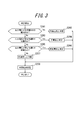
- FIG. 2 is a flowchart showing the procedure for determining the power supply device in the first embodiment.
- the control unit 103 of the power device determination apparatus 100 turns on the power supply devices 1a to 1e (step S101).
- the control unit 103 boosts only the output power of the power supply device 1a by the voltage converter 3a (step S102).
- the voltage converters 3b to 3e are not operated, and the input side of the inverter 6 of the voltage converters 3b to 3e is open. Accordingly, the outputs of the voltage converters 3b to 3e do not affect the output voltage of the voltage converter 3a and the measurement result of the voltage measuring device 4a.
- control unit 103 After boosting in step S102, the control unit 103 measures the boosted output voltage of the power supply device 1a by the voltage measuring device 4a (step S103). The control unit 103 determines the power supply device 1a based on the measurement result of the output voltage (step S104).
- FIG. 3 shows in detail a flowchart of the determination procedure of the power supply devices 1a to 1e in step S104.
- the control unit 103 determines whether the output voltage measurement result of the voltage converter 3a by the voltage measuring device 4a is within the predetermined range A shown in Table 1 (step S201). When the control unit 103 determines that the power source device 1a is within the predetermined range A, the power supply device 1a is determined to be a “solar cell” (step S202). The control unit 103 stores the determination result of the power supply device 1a in the storage unit 12 in the control unit 103 (step S208), and the determination ends.
- step S105 the control unit 103 boosts only the output power of the power supply device 1b by the voltage converter 3b (step S105).
- step S102 the voltage converters 3a and 3c to 3e are not operated, and the inverter 6 input side of the voltage converters 3a and 3c to 3e is open. Accordingly, the outputs of the voltage converters 3a and 3c to 3e do not affect the output voltage of the voltage converter 3b and the measurement result of the voltage measuring device 4b.
- the control unit 103 measures the boosted output voltage of the power supply device 1b by the voltage measuring device 4b (step S106), and determines the power supply device 1b based on the result (step S106). Step S107).
- the control unit 103 determines whether or not the output voltage measurement result of the voltage converter 3b by the voltage measuring device 4b is within the predetermined range A shown in Table 1 (step S201). When the control unit 103 determines that the power supply device 1b is within the predetermined range A, the power supply device 1b is determined to be a “solar cell” (step S202), and the determination result of the power supply device 1b is stored in the storage unit 12 in the control unit 103. Store (step S208), and the determination ends. The power supply device 1c is also determined to be a “solar cell” by the same procedure as described above.
- step S111 the control unit 103 boosts only the output power of the power supply device 1d by the voltage converter 3d (step S111).
- step S102 the voltage converters 3a to 3c and 3e are not operated, and the inverter 6 input side of the voltage converters 3a to 3c and 3e is open. Therefore, the outputs of the voltage converters 3a to 3c and 3e do not affect the output voltage of the voltage converter 3d and the measurement result of the voltage measuring device 4d.
- step S112 the control unit 103 measures the output voltage after boosting the power supply device 1d by the voltage measuring device 4d (step S112), and determines the power supply device 1d based on the result (step S112). Step S113).
- the control unit 103 determines whether or not the output voltage measurement result of the voltage converter 3d by the voltage measuring device 4d is within the predetermined range A shown in Table 1 (step S201), and is not within the predetermined range A. If it judges, it will be judged whether it is in the range of the predetermined range B next (step S203). If the controller 103 determines that it is not within the range of the predetermined range B, it is next determined whether or not it is within the range of the predetermined range C (step S205).
- the control unit 103 determines that the power supply device 1d is within the predetermined range C
- the power supply device 1d is determined to be a “fuel cell” (step S206), and the determination result of the power supply device 1d is stored in the storage unit 12 in the control unit 103.
- Store step S208
- the determination ends. If it is determined in step S205 that it is not within the range of the predetermined range C, it is determined that the assumed power supply device is not connected (step S207), and the determination result is stored in the storage unit 12 in the control unit 103 ( Step S208), the determination is terminated.
- step S114 the control unit 103 boosts only the output power of the power supply device 1e by the voltage converter 3e (step S114).
- step S102 the voltage converters 3a to 3d are not operated, the inverter 6 input side of the voltage converters 3a to 3d is open, and the outputs of the voltage converters 3a to 3d are output from the voltage converter 3e.
- the output voltage and the measurement result of the voltage measuring device 4e are configured so as not to have any influence.
- the control unit 103 measures the boosted output voltage of the power supply device 1e by the voltage measuring device 4e (step S115), and determines the power supply device 1e based on the result (step S115). Step S116).
- the control unit 103 determines whether or not the output voltage measurement result of the voltage converter 3e by the voltage measuring device 4e is within the predetermined range A shown in Table 1 (step S201). If the control unit 103 determines that it is not within the range of the predetermined range A, it next determines whether it is within the range of the predetermined range B (step S203). When the control unit 103 determines that the power source device 1e is within the predetermined range B, the power source device 1e is determined to be a “storage battery” (step S204), and the determination result of the power source device 1e is stored in the storage unit 103. 12 (step S208), and the determination ends.
- the control unit 103 ends the device determination mode after determining all the power supply devices.
- Table 1 the range of the predetermined range A corresponding to the output voltage of the solar cell is set wider than the predetermined range B corresponding to the storage battery and the range of the predetermined range C corresponding to the fuel cell. This is because the output of a solar cell is likely to fluctuate depending on fluctuations in the amount of sunlight.
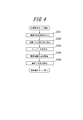
- FIG. 4 is a flowchart showing an operation procedure in the steady operation mode in the first embodiment.
- the control unit 103 reads the device determination result obtained through the device determination mode from the storage unit 12 in the control unit 103 (step S301). Based on the read device determination result, the control unit 103 sets the boost ratio shown in Table 2 for the voltage converters 3a to 3e (step S302). For example, since the determination results of the power supply devices 1a to 1c read in step S302 are all “solar cells”, the control unit 103 converts the voltage conversion corresponding to the power supply devices 1a to 1c based on the correspondence table of Table 2. 1.25 is set as the step-up ratio of the devices 3a to 3c.
- the control unit 103 determines the boost ratio of the voltage converter 3d corresponding to the power supply device 1d based on the correspondence table of Table 2. Set 1.88. Further, since the determination result of the power supply device 1e read in step S301 is “storage battery”, the control unit 103 sets the boost ratio of the voltage converter 3e corresponding to the power supply device 1e as 1. based on the correspondence table of Table 2. 58 is set. By setting these step-up ratios, the output voltage of each power supply device from the voltage converters 3a to 3e is theoretically DC 300V, which is a DC link voltage.
- the control unit 103 sets the inverter 6 so that the inverter 6 converts DC 300V input power into single-phase AC 200V power (step S303).
- the inverter 6, the switches 7a and 7b, and the load connection terminals 8a and 8b are not included in the power supply device determination device of the present invention, but are described as included in the power conversion device.
- the power device determination apparatus may be configured to include these.
- control unit 103 starts output from the power supply devices 1a to 1e (step S304) and confirms that the output power from the voltage converters 3a to 3e is about DC 300V.
- Output power from the voltage converters 3 a to 3 e is DC-linked and input to the inverter 6.
- the control unit 103 also monitors the voltage after passing through the inverter 6, confirms that a predetermined AC voltage of 200V is obtained, and then turns on the switch 7a to start supplying power to the load 9 (Step S103). S305).
- control unit 103 may be configured by hardware, or a function may be realized by causing a CPU to execute a program.
- the output voltages of the voltage converters 3a to 3e are measured by the individual voltage measuring devices 4a to 4e.
- the present invention is not limited to this, and for example, a single voltage measurement is performed. Only the vessel 4 may be provided. That is, at the timing of steps S103, S106, S109, S112, and S115 in FIG. 2, the control unit 103 switches the input to the voltage measuring device 4 with a multiplexer, and the voltage measuring device 4 changes the output voltages of the voltage converters 3a to 3e. You may comprise so that it can measure sequentially.
- inverter 6 in this embodiment described having controlled the output voltage by the control part 103, this invention is not limited to this, You may set up so that it may become a predetermined output voltage.
- a single-phase three-wire AC 200V is output from the load connection terminal 8a as an AC power output.
- an inverter 6 ′ for converting to three-phase 200 V may be arranged in place of the inverter 6 in order to cope with a commercial refrigerator, air conditioner, motor drive in a factory, and the like.
- the description has been made on the assumption that an electric device that can be used in Japan as a load to be connected.
- the load can be appropriately changed in consideration of the use of an electric device that can be used outside of Japan.
- the control unit 103 may control the inverter 6 so as to output AC 220 to 240V, or an inverter 6 ′′ that can output AC 220 to 240V may be arranged instead of the inverter 6.
- Electrical devices that can be used in Asia, Oceania and Europe can also be configured to be connectable.
- the type of the connected power supply device is automatically determined in the device determination mode, and the output power of each power supply device is boosted in the steady operation mode based on the determination result. It was configured to set the ratio automatically. As a result, the user can individually check the type of the connected power supply device or manually set the DC / DC converter so as to boost the output voltage at the boost ratio corresponding to the type of the device. It becomes unnecessary.
- the voltage monitoring of the power supply device is always performed even during steady operation, and the type of the power supply device can be determined using the voltage measuring devices 4a to 4e used for the voltage monitoring. Therefore, the power supply device can be determined without adding any special circuit.
- FIG. 5 is a block diagram showing a configuration of the power conversion device 113 including the power supply device determination device 110 according to the second embodiment of the present invention.
- the power supply device determination apparatus 110 includes a power supply device connection unit 101 for connecting a plurality of power supply devices, a voltage measurement unit 111 for measuring an output voltage from each power supply device, and each component. And a control unit 112 for controlling.
- the power converter device 113 is further provided with the load connection part 104 for connecting with a load.
- the configurations of the power supply device connection unit 101 and the load connection unit 104 are the same as those of the first embodiment of the present invention, and thus detailed description thereof is omitted.
- voltage measurement is different from the configuration of the first embodiment.
- the unit 111 and the control unit 112 will be described.
- the voltage measuring unit 111 includes voltage measuring devices 4a to 4e for measuring the voltage of the DC power output from the voltage converters 3a to 3e.
- the connection switches 5a to 5e are further provided in the subsequent stage of the voltage converters 3a to 3e and in the previous stage of the inverter 6.
- the connection switches 5a to 5e are controlled by the control unit 112 and are turned off in the device determination mode so that the voltage of the power supply device output after boosting can be individually monitored.
- the connection switches 5 a to 5 e are turned on, and the outputs of the respective power supply devices are DC-linked at the previous stage of the inverter 6 and controlled to be input to the inverter 6.
- the control unit 112 controls the power supply devices 1a to 1e, the voltage converters 3a to 3e, the voltage measuring devices 4a to 4e, the connection switches 5a to 5e, the inverter 6, the switches 7a and 7b, and the load 9 according to the control signal 11 shown in FIG. These components can be controlled in various ways. Specifically, the control unit 112 controls the ON / OFF of the power supply devices 1a to 1e, sets the step-up ratio of the voltage converters 3a to 3e, controls the voltage measuring devices 4a to 4e and reads the measured values, and connects the switch 5a. Control of 5 to 5e, setting of the inverter 6, control of the switches 7a and 7b, ON / OFF control of the load 9, etc. are possible.
- the device determination mode for determining the type of the power supply device and the subsequent steady operation mode in the second embodiment will be individually described below.
- the voltage converters 3a to 3e in the power device connection unit 101 boost the output power of the power devices 1a to 1e with the same boost ratio.
- the output power of the power supply devices 1a to 1e is boosted at the same boost ratio 1.2, and the output power is input to the voltage measuring devices 4a to 4e.
- an arbitrary value of 1 or more and 2 or less can be set as the step-up ratio in this device determination mode.
- FIG. 6 is a flowchart showing the procedure for determining the power supply device in the second embodiment.
- the control unit 112 of the power supply device determination device 110 first turns off the connection switches 5a to 5e and cancels the DC link of the output power from the voltage converters 3a to 3e (step S401).
- the control unit 112 turns on the outputs of the power supply devices 1a to 1e all at once (step S402), and boosts the output power of the power supply devices 1a to 1e by the voltage converters 3a to 3e (step S403).
- control unit 112 After boosting at step S403, the control unit 112 measures the boosted output voltage of the power supply devices 1a to 1e by the voltage measuring devices 4a to 4e (step S404), and the measurement result is stored in the control unit 112. Store in the storage unit 12 (step S405). The control unit 112 determines the power supply devices 1a to 1e based on the stored output voltage measurement result (steps S406 to S410), and ends the device determination mode.
- FIG. 7 shows in detail a flowchart of the determination procedure of the power supply devices 1a to 1e in steps S406 to S410.
- the control unit 112 reads the corresponding output voltage measurement result stored in the storage unit 12 (step S501). Next, it is determined whether or not the read output voltage measurement result is within the range of the predetermined range A shown in Table 1 (step S502). It is determined that there is (step S503).
- the control unit 112 stores the determination result of the power supply device 1a in the storage unit 12 in the control unit 112 (step S509), and the determination ends.
- the control unit 112 next determines whether or not the read output voltage measurement result is within the predetermined range B shown in Table 1 (step S504).
- the control unit 112 determines that it is within the range of the predetermined range B, it is determined that the power supply device is a “storage battery” (step S505), and the determination result of the power supply device is stored in the storage unit 12 in the control unit 112 ( In step S509), the determination ends. If it is determined that it is not within the range of the predetermined range B, then the control unit 112 determines whether or not the read output voltage measurement result is within the range of the predetermined range C shown in Table 1 (step S506).
- the control unit 112 determines that the power supply device is within the predetermined range C
- the power supply device is determined to be a “fuel cell” (step S507), and the determination result of the power supply device is stored in the storage unit 12 in the control unit 112.
- the determination ends When the read output voltage measurement result does not correspond to any of the predetermined ranges A to C, it is determined that there is no connection (step S508), and the determination result of the power supply device is stored in the storage unit 12 in the control unit 112. (Step S509), the determination ends.
- the control unit 112 ends the device determination mode after determining all the power supply devices.
- FIG. 8 is a flowchart showing an operation procedure in the steady operation mode in the second embodiment.
- the control unit 112 reads the device determination result obtained through the device determination mode from the storage unit in the control unit 112 (step S601). Based on the read device determination result, the control unit 112 sets the step-up ratio described in Table 2 for the voltage converters 3a to 3e (step S602). For example, since the determination results of the power supply devices 1a to 1c read out in step S601 are all “solar cells”, the control unit 112 performs voltage conversion corresponding to the power supply devices 1a to 1c based on the correspondence table of Table 2. 1.25 is set as the step-up ratio of the devices 3a to 3c.
- the control unit 112 determines the boost ratio of the voltage converter 3d corresponding to the power supply device 1d based on the correspondence table of Table 2. Set 1.88. Further, since the determination result of the power supply device 1e read out in step S601 is “storage battery”, the control unit 112 sets the boost ratio of the voltage converter 3e corresponding to the power supply device 1e as 1. based on the correspondence table of Table 2. 58 is set. By setting these step-up ratios, the output voltage of each power supply device from the voltage converters 3a to 3e is theoretically about 300V.
- the control unit 112 starts outputting power from the power supply device (step S603).
- the power from the power supply device 1a will be described as an example.
- the control unit calculates a ratio between the DC link voltage Vd (300 V in this embodiment) and the boosted output voltage Vac of the power supply device 1a to obtain a predetermined threshold value. It is confirmed that the expression (1) is satisfied for ⁇ (step S604). If the expression (1) is not satisfied, the step-up ratio preset in step S602 is corrected (step S605). Specifically, the boost ratio is changed so that the boost ratio Rad represented by Expression (2) is obtained when the corrected boost ratio is Rad and the uncorrected boost ratio is Rac.
- the above procedure is continued until the boosted output voltages Vac to Vec of all power supply devices satisfy the expression (1).
- the subscript a in the expressions (1) and (2) indicates that the relational expression is related to the power supply device 1a, and the subscripts b to e are replaced with the subscripts b to e, respectively. Shall.
- control unit 112 sets the inverter 6 so as to convert DC 300V input power to the inverter 6 into single-phase AC 200V power (step S606).
- the inverter 6, the switches 7a and 7b, and the load connection terminals 8a and 8b are not included in the power supply device determination device of the present invention, but are included in the power conversion device of the present invention.
- the power supply device determination apparatus may be configured to include these.
- control unit 112 turns on the connection switches 5a to 5e and monitors the voltage after passing through the inverter 6. Then, after confirming that the predetermined AC 200V is obtained, the control unit 112 turns on the switch 7a and starts supplying power to the load 9 (step S608).
- connection switches 5a to 5e are provided at the subsequent stage of the voltage converters 3a to 3e, and the connection switches are turned off in the device determination mode. .
- the boosting ratio is corrected from the ratio of the boosted output voltage of the power supply device and the DC link voltage.
- the third embodiment of the present invention has the same hardware configuration as that of the second embodiment, although the operation of the control unit 112 is different from that of the first and second embodiments. Therefore, in the following description, the block diagram of FIG. 5 is referred for the configuration of the present embodiment.
- the device determination mode for determining the type of power supply device and the subsequent steady operation mode in the third embodiment will be individually described below.
- the voltage converters 3a to 3e in the power device connection unit 101 boost the output power of the power devices 1a to 1e with the same boost ratio.
- the output power of the power supply devices 1a to 1e is boosted at the same boost ratio 1.2, and the output power is input to the voltage measuring devices 4a to 4e.
- an arbitrary value of 1 or more and 2 or less can be set as the step-up ratio in this device determination mode.
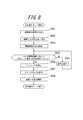
- FIG. 9 is a flowchart showing the procedure for determining the power supply device in the third embodiment.
- the control unit 112 of the power supply device determination device 110 first turns off the connection switches 5a to 5e and cancels the DC link of the output power from the voltage converters 3a to 3e (step S701).
- the control unit 112 turns on the outputs of the power supply devices 1a to 1e all at once (step S702), and boosts the output power of the power supply devices 1a to 1e by the voltage converters 3a to 3e (step S703).
- the control unit 112 measures the boosted output voltage of the power supply devices 1a to 1e using the voltage measuring devices 4a to 4e (step S704).
- the control unit 112 stores the output voltage measurement result in the storage unit 12 in the control unit 112 (step S705).
- the control unit 112 calculates the optimum boost ratio for each power supply device 1a to 1e based on the stored output voltage measurement result. More specifically, for example, in step S703 of the power supply device 1a, when the output voltage after boosting with the boost ratio Rf is Vaf, the control unit 112 uses the DC link voltage Vd as the optimum boost ratio Rad of the power supply device 1a. It is calculated by the following equation (3). Note that the subscript a in the expression (3) indicates that the relational expression is related to the power supply device 1a, and the subscripts b to e are replaced with the subscripts b to e to indicate the relational expressions regarding the power supply devices 1b to 1e, respectively.
- the control unit 112 calculates the optimum boost ratios Rad to Red for all the power supply devices 1a to 1e (step S706), and stores the calculation results in the storage unit 12 in the control unit 112 (step S707). Thereafter, the device determination mode ends.
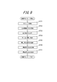
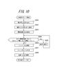
- FIG. 10 is a flowchart showing an operation procedure in the steady operation mode in the third embodiment.
- the control unit 112 reads the calculation result of the optimum boost ratio for each device obtained through the device determination mode from the storage unit 12 in the control unit 112 (step S801). Based on the read calculation result, the control unit 112 sets an optimum step-up ratio for the voltage converters 3a to 3e (step S802). By setting these optimum boost ratios, the output voltages of the power supply devices from the voltage converters 3a to 3e theoretically become DC link voltages.
- the control unit 112 starts outputting power from the power supply device (step S803).
- the control unit calculates a ratio between the DC link voltage Vd (300 V in the present embodiment) and the output voltage Vac after boosting the power supply device, and sets the predetermined threshold value ⁇ .
- the expression (1) is satisfied (step S804).
- the boost ratio is corrected (step S805). Specifically, the boost ratio is changed so that the boost ratio expressed by the equation (2) is obtained when the corrected boost ratio is Rad and the uncorrected boost ratio is Rac. The above operation is continued until the boosted output voltages Vac to Vec satisfy the expression (1) for all the power supply devices 1a to 1e.
- control unit 112 sets the inverter 6 so as to convert DC 300V input power to the inverter 6 into single-phase AC 200V power (step S806).
- the inverter 6, the switches 7a and 7b, and the load connection terminals 8a and 8b are not included in the power supply device determination device of the present invention, but are included in the power conversion device of the present invention.
- the power supply device determination apparatus may be configured to include these.
- control unit 112 turns on the connection switches 5a to 5e (step S807) and monitors the voltage after passing through the inverter 6. Then, after confirming that a predetermined AC voltage of 200 V is obtained, the control unit 112 turns on the switch 7a and starts supplying power to the load 9 (step S808).
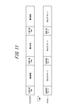
- the device determination mode and the steady operation mode shown in FIGS. 9 and 10 can be repeatedly executed. Specifically, as shown in FIG. 11, even after shifting from the device determination mode to the steady operation mode, the device determination mode is periodically executed, and the boost ratio is always determined based on the latest output voltage of the power supply device. It can be constituted as follows. Note that when the device determination mode is executed, the switch 7a is turned off and the switch 7b is turned on to supply power to the load from the commercial power supply system 10 as shown in FIG. .
- the optimum boost ratio is calculated from the ratio of the output voltage and the DC link voltage with the fixed boost ratio, an unknown power supply device is connected.
- the switch 7b may be appropriately turned on according to the excess or deficiency of power supply from the power supply device, and connected to the commercial power supply system.
- Computer systems and other hardware include, for example, general-purpose computers, PCs (personal computers), dedicated computers, workstations, PCS (Personal Communications System, personal mobile communication systems), RFID receivers, electronic notepads, laptop computers, A GPS (Global Positioning System) receiver or other programmable data processing device is included.
- the various operations are performed by dedicated circuitry implemented with program instructions (software) (eg, individual logic gates interconnected to perform a specific function) or one or more processors. Note that it is executed by a logic block, a program module, or the like.
- microprocessors include, for example, one or more microprocessors, CPU (Central Processing Unit), ASIC (Application Specific Integrated Circuit), DSP (Digital Signal Processor), PLD (Programmable Logic (Device), FPGA (Field Programmable Gate Array), processor, controller, microcontroller, microprocessor, electronics, other devices designed to perform the functions described here, and / or any combination of these It is.
- the embodiments shown here are implemented, for example, by hardware, software, firmware, middleware, microcode, or any combination thereof.
- the instructions may be program code or code segments for performing the necessary tasks.
- the instructions can then be stored on a machine-readable non-transitory storage medium or other medium.
- a code segment may represent any combination of procedures, functions, subprograms, programs, routines, subroutines, modules, software packages, classes or instructions, data structures or program statements.
- a code segment transmits and / or receives information, data arguments, variables or stored contents with other code segments or hardware circuits, thereby connecting the code segments with other code segments or hardware circuits .
- the network used here is the Internet, ad hoc network, LAN (Local Area Network), cellular network, WPAN (Wireless Personal Area Network) or other network, or any combination of these. Is included.
- Examples of the components of the wireless network include an access point (for example, a Wi-Fi access point), a femto cell, and the like.
- wireless communication devices include Wi-Fi, Bluetooth (registered trademark), cellular communication technology (for example, CDMA (Code Division Multiple Access), TDMA (Time Division Multiple Access), FDMA (Frequency Division Multiple Access), OFDMA (Orthogonal Frequency Frequency). Division (Multiple Access), SC-FDMA (Single-Carrier Frequency Division Multiple Access), or other wireless technologies and / or wireless standards using technology standards.
- the machine-readable non-transitory storage medium used herein can be further configured as a computer readable tangible carrier (medium) comprised of solid state memory, magnetic disk and optical disk categories, and so on.
- the medium stores an appropriate set of computer instructions such as a program module for causing a processor to execute the technology disclosed herein, and a data structure.
- Computer readable media include electrical connections with one or more wires, magnetic disk storage media, magnetic cassettes, magnetic tape, and other magnetic and optical storage devices (eg CD (Compact Disk), laser disks ( Registered trademark), DVD (registered trademark) (Digital Versatile Disc), floppy (registered trademark) disk and Blu-ray Disc (registered trademark)), portable computer disk, RAM (Random Access Memory), ROM (Read-Only Memory), It includes a rewritable and programmable ROM such as EPROM, EEPROM or flash memory or other tangible storage medium capable of storing information or any combination thereof.
- the memory can be provided inside and / or outside the processor / processing unit.
- the term “memory” means any type of long-term storage, short-term storage, volatile, non-volatile, or other memory in which a particular type or number of memories or storage is stored. The type of medium is not limited.
Landscapes
- Engineering & Computer Science (AREA)
- Power Engineering (AREA)
- Physics & Mathematics (AREA)
- General Physics & Mathematics (AREA)
- Dc-Dc Converters (AREA)
- Direct Current Feeding And Distribution (AREA)
- Control Of Electrical Variables (AREA)
- Inverter Devices (AREA)
Priority Applications (3)
| Application Number | Priority Date | Filing Date | Title |
|---|---|---|---|
| CN201480042632.2A CN105409081B (zh) | 2013-07-29 | 2014-07-28 | 电源设备判断装置、电源设备判断方法以及电力转换装置 |
| US14/908,409 US10164438B2 (en) | 2013-07-29 | 2014-07-28 | Power-supply device determination apparatus, power-supply device determination method, and power conversion apparatus |
| EP14832635.8A EP3029794B1 (de) | 2013-07-29 | 2014-07-28 | Vorrichtung zur identifikation einer stromversorgungsvorrichtung, verfahren zur identifikation einer stromversorgungsvorrichtung sowie stromwandlervorrichtung |
Applications Claiming Priority (2)
| Application Number | Priority Date | Filing Date | Title |
|---|---|---|---|
| JP2013157085A JP6158628B2 (ja) | 2013-07-29 | 2013-07-29 | 電源機器判定装置、電源機器判定方法及び電力変換装置 |
| JP2013-157085 | 2013-07-29 |
Publications (1)
| Publication Number | Publication Date |
|---|---|
| WO2015015794A1 true WO2015015794A1 (ja) | 2015-02-05 |
Family
ID=52431350
Family Applications (1)
| Application Number | Title | Priority Date | Filing Date |
|---|---|---|---|
| PCT/JP2014/003960 Ceased WO2015015794A1 (ja) | 2013-07-29 | 2014-07-28 | 電源機器判定装置、電源機器判定方法及び電力変換装置 |
Country Status (5)
| Country | Link |
|---|---|
| US (1) | US10164438B2 (de) |
| EP (1) | EP3029794B1 (de) |
| JP (1) | JP6158628B2 (de) |
| CN (1) | CN105409081B (de) |
| WO (1) | WO2015015794A1 (de) |
Families Citing this family (9)
| Publication number | Priority date | Publication date | Assignee | Title |
|---|---|---|---|---|
| CN105409080B (zh) * | 2013-07-29 | 2019-06-11 | 京瓷株式会社 | 电力转换装置、控制电力转换装置的方法以及电力转换系统 |
| EP3232529A1 (de) * | 2016-04-14 | 2017-10-18 | DET International Holding Limited | Stromversorgungsanordnung |
| CN106288610B (zh) * | 2016-08-09 | 2019-01-08 | 江苏欧莱特新能源科技有限公司 | 一种大中型冷库专用制冷系统 |
| KR102356691B1 (ko) * | 2018-09-27 | 2022-01-27 | 한국전자기술연구원 | 다중의 주변 에너지원을 이용한 에너지 하베스팅 시스템 |
| WO2021107198A1 (ko) | 2019-11-28 | 2021-06-03 | 전자부품연구원 | 다중의 주변 에너지원을 이용한 에너지 하베스팅 시스템 |
| DE202021102361U1 (de) * | 2021-04-30 | 2021-05-11 | Tesvolt Gmbh | Monitoring-Einrichtung und Monitoring-System zur Kontrolle und/ oder Steuerung wenigstens eines elektrischen Parameters in einem elektrischen Versorgungssystem und Computerprogramm |
| AU2023376548A1 (en) * | 2022-11-07 | 2025-04-17 | Fronius International Gmbh | Inverter system and method for operating said inverter system |
| US12395075B2 (en) * | 2023-02-21 | 2025-08-19 | Canon Kabushiki Kaisha | Electronic apparatus and control method |
| CN116404724B (zh) * | 2023-05-29 | 2023-08-25 | 深圳市驰普科达科技有限公司 | 户外电源及其控制方法、并联连接线和户外电源组件 |
Citations (3)
| Publication number | Priority date | Publication date | Assignee | Title |
|---|---|---|---|---|
| JP2002218654A (ja) | 2001-01-24 | 2002-08-02 | Furukawa Electric Co Ltd:The | 太陽光発電システム |
| JP2012100504A (ja) * | 2010-11-05 | 2012-05-24 | Creative Techno Solution Co Ltd | 電力供給システム |
| WO2012132948A1 (ja) * | 2011-03-30 | 2012-10-04 | 三洋電機株式会社 | 電力変換システム |
Family Cites Families (7)
| Publication number | Priority date | Publication date | Assignee | Title |
|---|---|---|---|---|
| JP2776105B2 (ja) * | 1992-01-07 | 1998-07-16 | 三菱電機株式会社 | 電子機器及び電子機器への電力供給方法 |
| US6633802B2 (en) * | 2001-03-06 | 2003-10-14 | Sikorsky Aircraft Corporation | Power management under limited power conditions |
| US8193661B2 (en) | 2009-02-17 | 2012-06-05 | Lineage Power Corporation | DC plant controller and method for selecting among multiple power sources and DC plant employing the same |
| CA2708001A1 (en) * | 2009-07-13 | 2011-01-13 | Lineage Power Corporation | System and method for combining the outputs of multiple, disparate types of power sources |
| US9240687B2 (en) * | 2010-10-04 | 2016-01-19 | The Boeing Company | Smart microgrid |
| US8648496B2 (en) * | 2010-11-11 | 2014-02-11 | The Boeing Company | Reconfigurable microgrid direct current interface |
| WO2014039088A1 (en) * | 2012-09-07 | 2014-03-13 | Access Business Group International Llc | System and method for bidirectional wireless power transfer |
-
2013
- 2013-07-29 JP JP2013157085A patent/JP6158628B2/ja active Active
-
2014
- 2014-07-28 WO PCT/JP2014/003960 patent/WO2015015794A1/ja not_active Ceased
- 2014-07-28 EP EP14832635.8A patent/EP3029794B1/de active Active
- 2014-07-28 US US14/908,409 patent/US10164438B2/en active Active
- 2014-07-28 CN CN201480042632.2A patent/CN105409081B/zh active Active
Patent Citations (3)
| Publication number | Priority date | Publication date | Assignee | Title |
|---|---|---|---|---|
| JP2002218654A (ja) | 2001-01-24 | 2002-08-02 | Furukawa Electric Co Ltd:The | 太陽光発電システム |
| JP2012100504A (ja) * | 2010-11-05 | 2012-05-24 | Creative Techno Solution Co Ltd | 電力供給システム |
| WO2012132948A1 (ja) * | 2011-03-30 | 2012-10-04 | 三洋電機株式会社 | 電力変換システム |
Also Published As
| Publication number | Publication date |
|---|---|
| JP6158628B2 (ja) | 2017-07-05 |
| EP3029794A1 (de) | 2016-06-08 |
| EP3029794B1 (de) | 2020-11-11 |
| EP3029794A4 (de) | 2017-03-15 |
| US10164438B2 (en) | 2018-12-25 |
| US20160197481A1 (en) | 2016-07-07 |
| CN105409081B (zh) | 2018-07-17 |
| CN105409081A (zh) | 2016-03-16 |
| JP2015027238A (ja) | 2015-02-05 |
Similar Documents
| Publication | Publication Date | Title |
|---|---|---|
| JP6334037B2 (ja) | 電力変換装置、電力変換装置の制御方法、及び電力変換システム | |
| WO2015015794A1 (ja) | 電源機器判定装置、電源機器判定方法及び電力変換装置 | |
| JP6289661B2 (ja) | 電力供給機器、電力供給システム及び電力供給機器の制御方法 | |
| US10211635B2 (en) | Power control system and control method of power control system | |
| US10243367B2 (en) | Power supply system, control method of power supply system, and power supply apparatus | |
| JP6205077B2 (ja) | 電力供給機器、電力供給システム、および電力供給方法 | |
| WO2016006256A1 (ja) | 発電システムの制御方法、発電システム、及び発電装置 | |
| JP5938679B2 (ja) | 双方向コンバータ | |
| JP6251288B2 (ja) | 電力制御システム、電力制御装置及び電力制御システムの制御方法 | |
| JPWO2016121389A1 (ja) | 電力供給装置、電力供給システム、および電力供給方法 | |
| JP6216066B2 (ja) | 電力制御システムの制御方法、電力制御システム、及び電力制御装置 | |
| US10523015B2 (en) | Power generation apparatus, power generation system, and power generation method |
Legal Events
| Date | Code | Title | Description |
|---|---|---|---|
| WWE | Wipo information: entry into national phase |
Ref document number: 201480042632.2 Country of ref document: CN |
|
| 121 | Ep: the epo has been informed by wipo that ep was designated in this application |
Ref document number: 14832635 Country of ref document: EP Kind code of ref document: A1 |
|
| WWE | Wipo information: entry into national phase |
Ref document number: 2014832635 Country of ref document: EP |
|
| WWE | Wipo information: entry into national phase |
Ref document number: 14908409 Country of ref document: US |
|
| NENP | Non-entry into the national phase |
Ref country code: DE |