WO2015015887A1 - Cathéter - Google Patents
Cathéter Download PDFInfo
- Publication number
- WO2015015887A1 WO2015015887A1 PCT/JP2014/064298 JP2014064298W WO2015015887A1 WO 2015015887 A1 WO2015015887 A1 WO 2015015887A1 JP 2014064298 W JP2014064298 W JP 2014064298W WO 2015015887 A1 WO2015015887 A1 WO 2015015887A1
- Authority
- WO
- WIPO (PCT)
- Prior art keywords
- guide wire
- shaft member
- catheter
- long
- long shaft
- Prior art date
- Legal status (The legal status is an assumption and is not a legal conclusion. Google has not performed a legal analysis and makes no representation as to the accuracy of the status listed.)
- Ceased
Links
Images




Classifications
-
- A—HUMAN NECESSITIES
- A61—MEDICAL OR VETERINARY SCIENCE; HYGIENE
- A61M—DEVICES FOR INTRODUCING MEDIA INTO, OR ONTO, THE BODY; DEVICES FOR TRANSDUCING BODY MEDIA OR FOR TAKING MEDIA FROM THE BODY; DEVICES FOR PRODUCING OR ENDING SLEEP OR STUPOR
- A61M25/00—Catheters; Hollow probes
- A61M25/01—Introducing, guiding, advancing, emplacing or holding catheters
- A61M25/09—Guide wires
- A61M25/09041—Mechanisms for insertion of guide wires
-
- A—HUMAN NECESSITIES
- A61—MEDICAL OR VETERINARY SCIENCE; HYGIENE
- A61L—METHODS OR APPARATUS FOR STERILISING MATERIALS OR OBJECTS IN GENERAL; DISINFECTION, STERILISATION OR DEODORISATION OF AIR; CHEMICAL ASPECTS OF BANDAGES, DRESSINGS, ABSORBENT PADS OR SURGICAL ARTICLES; MATERIALS FOR BANDAGES, DRESSINGS, ABSORBENT PADS OR SURGICAL ARTICLES
- A61L29/00—Materials for catheters, medical tubing, cannulae, or endoscopes or for coating catheters
- A61L29/04—Macromolecular materials
-
- A—HUMAN NECESSITIES
- A61—MEDICAL OR VETERINARY SCIENCE; HYGIENE
- A61L—METHODS OR APPARATUS FOR STERILISING MATERIALS OR OBJECTS IN GENERAL; DISINFECTION, STERILISATION OR DEODORISATION OF AIR; CHEMICAL ASPECTS OF BANDAGES, DRESSINGS, ABSORBENT PADS OR SURGICAL ARTICLES; MATERIALS FOR BANDAGES, DRESSINGS, ABSORBENT PADS OR SURGICAL ARTICLES
- A61L29/00—Materials for catheters, medical tubing, cannulae, or endoscopes or for coating catheters
- A61L29/14—Materials characterised by their function or physical properties, e.g. lubricating compositions
-
- A—HUMAN NECESSITIES
- A61—MEDICAL OR VETERINARY SCIENCE; HYGIENE
- A61M—DEVICES FOR INTRODUCING MEDIA INTO, OR ONTO, THE BODY; DEVICES FOR TRANSDUCING BODY MEDIA OR FOR TAKING MEDIA FROM THE BODY; DEVICES FOR PRODUCING OR ENDING SLEEP OR STUPOR
- A61M25/00—Catheters; Hollow probes
- A61M25/0021—Catheters; Hollow probes characterised by the form of the tubing
- A61M25/0023—Catheters; Hollow probes characterised by the form of the tubing by the form of the lumen, e.g. cross-section, variable diameter
- A61M25/0026—Multi-lumen catheters with stationary elements
-
- A—HUMAN NECESSITIES
- A61—MEDICAL OR VETERINARY SCIENCE; HYGIENE
- A61M—DEVICES FOR INTRODUCING MEDIA INTO, OR ONTO, THE BODY; DEVICES FOR TRANSDUCING BODY MEDIA OR FOR TAKING MEDIA FROM THE BODY; DEVICES FOR PRODUCING OR ENDING SLEEP OR STUPOR
- A61M25/00—Catheters; Hollow probes
- A61M25/0043—Catheters; Hollow probes characterised by structural features
-
- A—HUMAN NECESSITIES
- A61—MEDICAL OR VETERINARY SCIENCE; HYGIENE
- A61M—DEVICES FOR INTRODUCING MEDIA INTO, OR ONTO, THE BODY; DEVICES FOR TRANSDUCING BODY MEDIA OR FOR TAKING MEDIA FROM THE BODY; DEVICES FOR PRODUCING OR ENDING SLEEP OR STUPOR
- A61M25/00—Catheters; Hollow probes
- A61M25/01—Introducing, guiding, advancing, emplacing or holding catheters
- A61M25/09—Guide wires
- A61M2025/09116—Design of handles or shafts or gripping surfaces thereof for manipulating guide wires
Definitions
- the present invention relates to a medical catheter.
- This application claims priority based on provisional application 61 / 860,383 filed in the United States on July 31, 2013, the contents of which are incorporated herein by reference.
- Patent Document 1 discloses a catheter having a guide wire lumen in the longitudinal axis direction of the catheter and an opening on the outer wall of the catheter.
- the guide wire is inserted into the bile duct and pancreatic duct from the duodenal papilla via the endoscope channel.
- the proximal end of the guide wire is inserted into the guide wire port at the distal end of the catheter.
- the guide wire can be taken out of the catheter through the opening by bending the catheter.
- the catheter is inserted into the endoscope channel and guided to the bile duct and pancreatic duct by the guide wire.
- a catheter is inserted into an endoscope channel without using a guide wire, and is inserted into a bile duct or pancreatic duct via a duodenal papilla.
- the guide wire is inserted into the guide wire lumen from the proximal port of the catheter, protrudes from the distal end of the catheter, and is placed in the bile duct or pancreatic duct. After that, when the catheter is pulled out with the guide wire in place, the guide wire is grasped from the guide wire port provided in the operation unit of the catheter protruding from the endoscope channel port near the endoscope operation unit. The guide wire is pulled out of the catheter from the opening provided in the catheter.
- the guide wire In the state where the guide wire is pulled out to the vicinity of the operation section of the endoscope, the guide wire can be fixed near the operation section of the endoscope with a hand or a fixing tool. In this state, when the catheter is pulled out from the endoscope channel, the guide wire inserted into the catheter is automatically pulled out from the opening.
- the catheter can be pulled out in a state where the guide wire is placed in a desired position of the bile duct or pancreatic duct by performing a cooperative operation of pulling out the catheter while pushing the guide wire.
- the present invention has been made in view of such circumstances, and an object thereof is to provide a catheter that is not easily broken while improving exchangeability and ease of pushing.
- a long catheter formed of a thermoplastic resin and having flexibility includes a long shaft member having a longitudinal axis, and a guide to the long shaft member at a distal end portion of the long shaft member.
- a guide wire lumen formed along the longitudinal axis so as to insert a wire; and a guide wire lumen that communicates with the guide wire lumen and is disposed at a proximal end of the guide wire lumen.
- a slit-shaped opening is formed along the longitudinal axis, and the edge is protruded in a direction approaching each other from a position facing the edge of the opening.
- the width of the opening is equal to or less than the diameter of the guide wire in a state where no external force is applied to the edge, and passively changes due to elastic deformation of the thermoplastic resin at the edge.
- the degree of crosslinking of the thermoplastic resin is greater than the degree of crosslinking of the edge.
- the cross-linking agent is cross-linked in the vicinity of the boundary between the guide wire lumen and the slit portion in the longitudinal direction of the long-axis member. Therefore, a protective part having a higher hardness than that when the crosslinking agent is not crosslinked may be provided.
- the protection portion is located from the boundary from a position closer to the distal end side of the long shaft member than the boundary between the guide wire lumen and the slit portion. May be provided so as to be connected to the position of the base end side of the long shaft member.
- the edge portion in a range from the proximal end of the guide wire lumen to a proximal end side of the long shaft member by a predetermined length is Along the longitudinal axis direction, the portion having a relatively high degree of crosslinking and the portion having a relatively low degree of crosslinking may be alternately arranged.
- the diameter of the long shaft member is orthogonal to a straight line connecting the opening and the opposite side of the opening.
- the projected area of the crosslinked portion of the thermoplastic resin at the edge is provided by the edge in the longitudinal-axis direction of the long-axis member.
- the projected area of the crosslinked portion of the thermoplastic resin other than the edge portion may be smaller.
- the distal end portion of the long shaft member within the range in which the slit portion is provided along the longitudinal axis direction of the long shaft member.
- the long axis member has a length in the longitudinal axis direction of the long axis member over the entire circumference, and the long axis member is uncrosslinked. Cross-linked regions may be provided alternately in the longitudinal axis direction of the long shaft member.
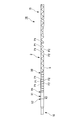
- FIG. 1 is a side view showing a catheter according to a first embodiment of the present invention.
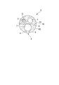
- FIG. 2 is a cross-sectional view taken along line AA in FIG.
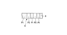
- FIG. 3 is a cross-sectional view taken along line BB in FIG. 2. It is a bottom view which shows a part of catheter which concerns on 1st Embodiment of this invention. It is a side view which shows the catheter which concerns on 2nd Embodiment of this invention.
- FIG. 6 is a cross-sectional view taken along the line CC of FIG.
- FIG. 6 is a cross-sectional view taken along the line DD of FIG.
- FIG. 6 is a cross-sectional view taken along line EE in FIG. 5.
- FIG. 1 is a side view showing a catheter 1 according to the first embodiment of the present invention.
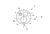
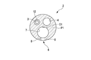
- FIG. 2 is a cross-sectional view taken along line AA in FIG. 3 is a cross-sectional view taken along line BB in FIG.
- FIG. 4 is a bottom view showing a part of the catheter 1 according to the first embodiment of the present invention.
- a catheter 1 according to this embodiment shown in FIG. 1 is a catheter used in combination with a known endoscope and a known medical guide catheter in order to incise the duodenal papilla.
- the catheter 1 includes a long shaft member 2, a distal end portion 10 disposed at the distal end of the long shaft member 2, and a proximal portion 15 disposed at the proximal end of the long shaft member 2.
- the long shaft member 2 shown in FIGS. 1 and 2 is made of a thermoplastic resin.
- the thermoplastic resin applied to the long shaft member 2 can be increased in hardness (rigidity) by being crosslinked.
- the long shaft member 2 is a long member formed of a thermoplastic resin containing a crosslinking agent that can be crosslinked by ionizing radiation.
- the long shaft member 2 may be a long member formed of a thermoplastic resin containing a crosslinking agent that can be cross-linked by heat.
- the long shaft member 2 has a long axis O1. Inside the long shaft member 2, a knife wire lumen 3, a liquid feeding lumen 4, a guide wire lumen 5, and a slit portion 6 are formed so as to extend in parallel with the longitudinal axis O1, respectively.
- the distal end of the knife wire lumen 3 extends from the distal end of the long shaft member 2 to the distal end portion of the distal end portion 10.
- the distal end of the knife wire lumen 3 opens at the outer peripheral surface of the distal end portion 10 at an incision portion 11 to be described later.
- the proximal end of the knife wire lumen 3 extends to the hand portion 15.
- the tip of the liquid feeding lumen 4 extends from the tip of the long shaft member 2 to the tip of the tip portion 10.
- the tip of the liquid feeding lumen 4 is open at the tip of the tip portion 10.
- the proximal end of the liquid feeding lumen 4 extends to the hand portion 15.
- the guide wire lumen 5 is opened at the tip of the tip portion 10 through a part of the tip portion of the long shaft member 2 and the inside of the tip portion 10.
- the guide wire lumen 5 has a cavity having a size that allows the guide wire to advance and retract in the direction of the central axis.
- the slit portion 6 includes a guide wire holding portion 7 and an edge portion 8.
- the guide wire holding part 7 has a cavity in which the guide wire can advance and retreat in the direction of its central axis.
- the edge portion 8 forms an opening for attaching / detaching the guide wire to / from the slit portion 6.
- the edge 8 is a region corresponding to the edge of the opening of the slit 6 in the cross section orthogonal to the longitudinal axis O1 of the long shaft member 2. In the cross section perpendicular to the longitudinal axis O1 of the long shaft member 2, the edge 8 has a first edge 8a and a second edge 8b.
- the first edge portion 8a and the second edge portion 8b are spaced apart from each other so as to have the opening of the slit 6 therebetween. Both the first edge portion 8a and the second edge portion 8b extend along the direction in which the longitudinal axis O1 of the long-axis member 2 extends.
- the distal end portion 10 shown in FIGS. 1 and 3 is a portion located in the distal end portion of the catheter 1 further than the distal end position of the slit portion 6.
- the distal end portion 10 includes a distal end portion of the knife wire lumen 3, a distal end portion of the liquid feeding lumen 4, a distal end portion of the guide wire lumen 5, and an incision portion 11 for incising the duodenal papilla.
- the incision 11 shown in FIG. 1 has a knife wire 12.
- the knife wire 12 is energized with a high frequency current to incise the duodenal papilla.
- the knife wire 12 is provided at the distal end portion of the distal end portion 10 so as to extend in the direction of the longitudinal axis O1 of the distal end portion 10.
- the distal end of the knife wire 12 is fixed to the distal end portion 10 in the knife wire lumen 3 at a part of the distal end portion of the distal end portion 10.
- the proximal end of the knife wire 12 is disposed so as to extend to the proximal portion 15 through the knife wire lumen 3.
- the knife wire 12 can be moved back and forth in the direction of its central axis.
- the portion exposed to the outside of the distal end portion 10 on the distal end side of the knife wire 12 is a portion in contact with the duodenal papilla in order to incise the duodenal papilla.
- the conductor is exposed so that a high-frequency current can be passed.
- a portion that is drawn into the knife wire lumen 3 when the distal end portion 10 is in a curved state and a portion that is located on the proximal side with respect to this portion are covered with an insulator.
- the hand portion 15 has a proximal end opening 16 of the slit portion 6.
- An operation unit 17 and a proximal connector 20 of the liquid feeding lumen 4 are attached to the hand portion 15.
- the operation unit 17 is provided for moving the knife wire 12 forward and backward.
- the base end opening portion 16 of the slit portion 6 has a shape in which the edge portion 8 is cut off so that the guide wire holding portion 7 is exposed.
- the 1 has a slider 18 and a plug 19.
- the slider 18 advances and retracts the knife wire 12 relative to the knife wire lumen 3.
- the plug 19 is provided to pass a high-frequency current through the knife wire 12.
- the catheter 1 of the present embodiment has a hardness for efficiently transmitting a pressing force from the hand portion 15 to the distal end portion 10, a flexibility for easily attaching and detaching the guide wire to and from the slit portion 6, and from the slit portion 6. It is configured in consideration of satisfying all of the durability against rough operation when removing the guide wire.
- the catheter 1 of the present embodiment has a predetermined cross-linking pattern having a cross-linked portion P1 and an uncross-linked portion P2 in the long shaft member 2, the distal end portion 10, and the proximal portion 15.
- the distal end portion 10 is bridged in a range from the boundary X1 between the guide wire lumen 5 and the slit portion 6 to a position X2 on the distal end side by a predetermined distance. Specifically, in the distal end portion 10, at least a portion X3 adjacent to the distal end side of the opening of the slit portion 6 in the longitudinal axis O1 direction of the long shaft member 2 is bridged.
- a portion X3 adjacent to the distal end side of the opening of the slit portion 6 is a substantially disc-shaped or substantially cylindrical region having a thickness in the direction of the longitudinal axis O1 of the long-axis member 2.
- the thickness dimension in the direction of the longitudinal axis O1 in the portion X3 adjacent to the distal end side of the opening of the slit portion 6 is large, the amount of tearing of the distal end portion 10 when the guide wire bites into the distal end portion 10 is reduced. Further, the thickness dimension in the direction of the longitudinal axis O1 in the portion X3 adjacent to the distal end side of the opening of the slit portion 6 may be set in consideration of the flexibility required for the portion X3.
- the bridge extends over the entire circumference of the distal end portion 10 in a range on the distal end side by a predetermined distance from the boundary X1 between the guide wire lumen 5 and the slit portion 6 and also includes the inside of the distal end portion 10 in the range. Has been.
- the long shaft member 2 is bridged from the boundary X1 between the guide wire lumen 5 and the slit portion 6 to a position X4 on the proximal end side by a predetermined distance.
- the entire length of the long shaft member 2 is extended in a range from the boundary X1 between the guide wire lumen 5 and the slit portion 6 to a position X4 on the proximal end side by a predetermined distance, and The inside of the long shaft member 2 within the range is also cross-linked.
- the inside of the long-axis member 2 is an outer peripheral surface of the long-axis member 2 and a region located on the inner side of the outer peripheral surface in a cross section orthogonal to the long-axis O1 of the long-axis member 2. 2 is a region excluding the cavity generated in FIG.
- the entire region from the position X2 on the distal end side from the boundary X1 to the position X4 on the proximal end side from the boundary X1 is bridged so as to include the boundary X1 between the guide wire lumen 5 and the slit portion 6.
- a portion X5 located on the opposite side of the opening of the slit portion 6 across the longitudinal axis O1 in the radial direction of the long shaft member 2 is cross-linked.
- This portion X5 is cross-linked, so that the force of forward / backward movement along the longitudinal axis O1 of the long shaft member 2 or the force of rotation operation around the longitudinal axis O1 of the long shaft member 2 is transferred from the hand portion 15 to the tip portion 10. It has a hardness that can be transmitted efficiently.
- the hardness of the long-axis member 2 is an elastic restoring force against a bending force such that the long-axis axis O1 of the long-axis member 2 is curved, and the long-axis member centering on the long-axis axis O1 of the long-axis member 2
- the long shaft member 2 has a rigidity capable of suitably transmitting the operation force amount while having a certain degree of flexibility.
- the long shaft member 2 is preferably plastically deformable, for example, following the curved shape of the treatment instrument channel of the endoscope, rather than being brittle with high hardness.
- the proximal portion 15 is cross-linked in the entire region from the proximal end of the proximal end opening 16 of the slit portion 6 to the proximal end side.
- the above is the bridge portion P1 in the present embodiment.
- the entire region on the distal end side of the long shaft member 2 is further uncrosslinked from the position X2 on the distal end side by a predetermined distance from the boundary X1 between the guide wire lumen 5 and the slit portion 6.
- the edge 8 is in an uncrosslinked state.
- the above is the uncrosslinked portion P2 in the present embodiment.
- the edge 8 contains a cross-linking agent but is not actively cross-linked. That is, the portion X5 located on the opposite side of the opening of the slit portion 6 across the longitudinal axis O1 in the radial direction of the long shaft member 2 has a higher degree of cross-linking than the edge portion 8, and therefore has a higher hardness than the edge portion 8. . Thereby, the part located on the opposite side to the opening of the slit portion 6 in the radial direction of the long shaft member 2 prevents buckling of the long shaft member 2 against the pressing force from the proximal portion 15 toward the distal end portion 10, and efficiently. Can transmit the pressing force.
- the edge 8 can be elastically deformed flexibly, and the guide wire can be easily attached and detached. Instead of having the uncrosslinked portion P2, it may have a low crosslinked portion having a relatively low degree of crosslinking as compared with the crosslinked portion P1.
- the catheter 1 according to this embodiment is continuously cross-linked in the range from the proximal end of the proximal portion 15 to the distal end of the long shaft member 2. For this reason, even if the pressing force for pushing the catheter 1 of the present embodiment into the treatment instrument channel of the endoscope is applied to the hand portion 15 and the long shaft member 2, the hand portion 15 and the long shaft member 2 are unlikely to buckle.
- the entire region on the distal end side of the long-axis member 2 and the edge portion 8 are further separated from the position X2 on the distal end side by a predetermined distance from the boundary X1 between the guide wire lumen 5 and the slit portion 6. It is in an uncrosslinked state.
- the distal end side of the long-axis member 2 is further easily bent by the pulling operation of the knife wire 12 than the position X 2 on the distal end side by a predetermined distance from the boundary X 1 between the guide wire lumen 5 and the slit portion 6. Deform to shape.
- edge portion 8 since the edge portion 8 is in an uncrosslinked state, the edge portion 8 is flexibly elastically deformed when the guide wire is inserted into the slit portion 6 through the opening or the guide wire is removed from the slit portion 6. For this reason, it is easy to attach and detach the guide wire.
- the guide wire may be attached to and detached from the catheter 1 during the treatment for the patient.
- the operation of separating the catheter 1 and the guide wire may be roughed for the purpose of shortening the treatment time.
- the tip of the slit portion 6 (the portion X3 adjacent to the tip side of the opening of the slit portion 6) is strongly pressed against the guide wire.
- the distal end of the slit portion 6 is reinforced by bridging, and the distal end of the slit portion 6 is difficult to tear.
- the entire region from the position X2 on the distal end side from the boundary X1 to the position X4 on the proximal end side from the boundary X1 is included so as to include the boundary X1 between the guide wire lumen 5 and the slit portion 6. It is cross-linked. Cross-linking in the region on the distal end side from the boundary X1 is such that when the guide wire is pressed against the boundary X1 from the boundary X1 toward the distal end side in order to separate the catheter 1 and the guide wire, the longitudinal axis of the long shaft member 2 is increased. The catheter 1 is prevented from tearing toward the distal end side in the direction of the axis O1.
- a force is not always applied only from the boundary X1 toward the distal end side along the longitudinal axis O1, and a force is obliquely forward from the boundary X1. It may take such a case.
- the entire region from the position X2 on the distal end side from the boundary X1 to the position X4 on the proximal end side from the boundary X1 is bridged. Thereby, the bridge
- the long shaft member 2 and the distal end portion 10 are caused by the force applied to the guide wire and the long shaft member 2. It is possible to prevent the catheter 1 from tearing from the boundary portion.
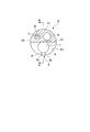
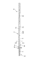
- FIG. 5 is a side view showing a catheter 1A according to a second embodiment of the present invention.
- 6 is a cross-sectional view taken along the line CC of FIG.
- FIG. 7 is a cross-sectional view taken along the line DD in FIG. 8 is a cross-sectional view taken along line EE in FIG.
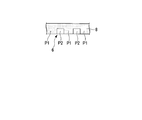
- FIG. 9 is a bottom view showing a part of the catheter 1A.
- the catheter 1 ⁇ / b> A of the present embodiment has a part of the edge 8 cross-linked. That is, in the present embodiment, the edge portion 8 is provided with a bridge portion P1 and an uncrosslinked portion P2.
- the catheter 1 ⁇ / b> A in the radial direction of the long shaft member 2, the catheter 1 ⁇ / b> A is orthogonal to a straight line L connecting the opening of the slit portion 6 and the opposite side thereof.
- the projected area of the portion where the thermoplastic resin is cross-linked in the edge 8 is the edge in the direction of the long axis O1 of the long axis member 2.
- it is smaller than the projected area of the portion where the thermoplastic resin other than the edge 8 is crosslinked. Even if it is such a structure, there exists an effect similar to 1st Embodiment.
- the portion that is cross-linked at the edge 8 has a relatively high hardness and thus the opening is difficult to open, but the portion that is in an uncrosslinked state at the edge 8 is relatively flexible. Opening is easy to open. For this reason, it becomes easy to attach / detach the guide wire to / from the slit portion 6 by starting attachment / detachment of the guide wire to / from the slit portion 6 at the uncrosslinked portion of the edge portion 8.
- the catheter 1A is manufactured so that the magnitude of the force required to attach / detach the guide wire to / from the slit 6 can be easily adjusted. can do.
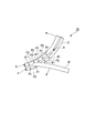
- FIG. 10 is a side view showing a catheter 1B of the third embodiment of the present invention.
- FIG. 11 is a side view showing a modification of the catheter 1B.
- FIG. 12 is a side view showing a further modification of the catheter 1B.
- FIG. 13 is a view for explaining the operation of the catheter 1B.
- the catheter 1B of the present embodiment has means for transmitting the positional relationship between the catheter 1B and the guide wire when the guide wire is removed from the catheter 1B to an operator who operates the catheter 1B.
- the catheter 1B of the present embodiment indicates that the guide wire has reached the vicinity of the distal end of the long shaft member 2 through the guide wire in the process of removing the guide wire from the slit portion 6 from the proximal end to the distal end of the long shaft member 2.
- the operator is made aware of the vibration transmitted.
- the edge portion 8 is provided in the catheter 1B.
- the edge portion 8 has a pattern in which the bridging portions P1 and the uncrosslinked portions P2 are alternately arranged in the direction of the longitudinal axis O1 of the long shaft member 2.
- the long axis along the linear direction D1 that is orthogonal to the straight line L that connects the opening of the slit portion 6 and the opposite side in the radial direction of the long shaft member 2 and extends in the radial direction of the long shaft member 2.
- the bridging portion P1 When the member 2 is viewed, in the region from the base X side position X4 to the base end side position X6 by a predetermined distance from the boundary X1 between the guide wire lumen 5 and the slit part 6, the bridging portion P1 is opened. It is formed in a wedge shape that gradually decreases toward the front.
- the bridging portion P1 has a first pattern that is provided side by side in the direction of the longitudinal axis O1 of the long shaft member 2 with a gap.
- the long axis is along the linear direction D1 that is orthogonal to the straight line L that connects the opening of the slit portion 6 and the opposite side in the radial direction of the long shaft member 2 and extends in the radial direction of the long shaft member 2.
- the bridging portion P1 is provided with a wedge shape that gradually decreases toward the opening in the longitudinal axis O1 direction of the long shaft member 2.
- the second pattern is provided.
- the distance between the bridging portions P1 in the region from the position X4 on the base end side by a predetermined distance from the boundary X1 between the guide wire lumen 5 and the slit portion 6 to the position X6 on the base end side by a predetermined length is, for example, about 20 mm.
- the edge 8 has a long region with a high degree of crosslinking and a region with a low degree of crosslinking.
- the shaft member 2 may have a pattern alternately arranged in the direction of the longitudinal axis O1.
- the bridging state of other portions may be appropriately set in this embodiment. .
- the bridging portion P1 and the uncrosslinked portion P2 at the edge 8 there is a difference in the amount of force required to remove the guide wire through the opening according to the difference in hardness.
- the bridging portions P1 and uncrosslinked portions P2 at the edge 8 are alternately provided in the direction of the longitudinal axis O1 of the long shaft member 2. Therefore, the amount of force required to remove the guide wire through the opening of the slit portion 6 is relatively large when passing through the bridging portion P1 in the process of removing the guide wire toward the distal end side of the long axis member 2 in the direction of the longitudinal axis O1. Large and relatively small when passing through the uncrosslinked portion P2. That is, as shown in FIG.
- the guide wire W alternately passes through the bridging portion P ⁇ b> 1 and the non-bridging portion P ⁇ b> 2 at the edge portion 8, so that the amount of force required to take out the guide wire W from the slit portion 6 is alternated. fluctuate.
- the fluctuation of the force required for taking out the guide wire from the slit portion 6 is perceived as vibration of the guide wire by the operator who takes out the guide wire.
- the fact that the guide wire has approached the tip of the slit 6 before the guide wire reaches the tip of the slit 6 can be transmitted to the operator as vibration of the guide wire and the catheter 1B. For this reason, it is possible to provide an opportunity for the operator to relax the force before the guide wire bites into the tip of the slit portion 6 and to prevent the tip of the slit portion 6 from tearing.
- Each of the above embodiments can provide a catheter that has high catheter exchangeability, is easy to push, and is not easily broken.
Landscapes
- Health & Medical Sciences (AREA)
- Life Sciences & Earth Sciences (AREA)
- Animal Behavior & Ethology (AREA)
- Veterinary Medicine (AREA)
- Public Health (AREA)
- General Health & Medical Sciences (AREA)
- Pulmonology (AREA)
- Heart & Thoracic Surgery (AREA)
- Hematology (AREA)
- Biomedical Technology (AREA)
- Anesthesiology (AREA)
- Engineering & Computer Science (AREA)
- Biophysics (AREA)
- Epidemiology (AREA)
- Media Introduction/Drainage Providing Device (AREA)
Abstract
L'invention concerne un cathéter comprenant : un élément allongé de tige, doté d'une longue tige ; une lumière pour fil guide formée dans la partie de pointe de l'élément allongé de tige le long de la longue tige de manière telle qu'un fil guide peut être inséré dans l'élément allongé de tige ; et des bords qui forment une ouverture en forme de fente, qui communique avec la lumière pour fil guide et qui est disposée en l'extrémité de base de la lumière pour fil guide, le long de la longue tige sur la surface circonférentielle externe de l'élément allongé de tige, et qui sont continus le long de la longue tige et qui font saillie l'un vers l'autre à partir de positions opposées sur le bord de l'ouverture. La largeur de l'ouverture n'est pas supérieure au diamètre du fil guide lorsqu'aucune force externe n'agit sur les bords et change de manière passive avec la déformation élastique de la résine thermoplastique des bords. Le degré de réticulation de la résine thermoplastique dans la partie de l'élément allongé de tige qui est située sur le côté opposé à l'ouverture dans la direction radiale est supérieur au degré de réticulation des bords.
Priority Applications (4)
| Application Number | Priority Date | Filing Date | Title |
|---|---|---|---|
| JP2014561209A JP5750621B1 (ja) | 2013-07-31 | 2014-05-29 | カテーテル |
| CN201480004211.0A CN104902951B (zh) | 2013-07-31 | 2014-05-29 | 导管 |
| EP14832019.5A EP3028733A4 (fr) | 2013-07-31 | 2014-05-29 | Cathéter |
| US14/789,387 US9561349B2 (en) | 2013-07-31 | 2015-07-01 | Catheter |
Applications Claiming Priority (2)
| Application Number | Priority Date | Filing Date | Title |
|---|---|---|---|
| US201361860383P | 2013-07-31 | 2013-07-31 | |
| US61/860,383 | 2013-07-31 |
Related Child Applications (1)
| Application Number | Title | Priority Date | Filing Date |
|---|---|---|---|
| US14/789,387 Continuation US9561349B2 (en) | 2013-07-31 | 2015-07-01 | Catheter |
Publications (1)
| Publication Number | Publication Date |
|---|---|
| WO2015015887A1 true WO2015015887A1 (fr) | 2015-02-05 |
Family
ID=52431432
Family Applications (1)
| Application Number | Title | Priority Date | Filing Date |
|---|---|---|---|
| PCT/JP2014/064298 Ceased WO2015015887A1 (fr) | 2013-07-31 | 2014-05-29 | Cathéter |
Country Status (5)
| Country | Link |
|---|---|
| US (1) | US9561349B2 (fr) |
| EP (1) | EP3028733A4 (fr) |
| JP (1) | JP5750621B1 (fr) |
| CN (1) | CN104902951B (fr) |
| WO (1) | WO2015015887A1 (fr) |
Cited By (2)
| Publication number | Priority date | Publication date | Assignee | Title |
|---|---|---|---|---|
| WO2016151935A1 (fr) * | 2015-03-25 | 2016-09-29 | オリンパス株式会社 | Instrument de traitement |
| WO2018167968A1 (fr) * | 2017-03-17 | 2018-09-20 | オリンパス株式会社 | Dispositif optique pour vaisseau sanguin et système optique pour vaisseau sanguin |
Families Citing this family (4)
| Publication number | Priority date | Publication date | Assignee | Title |
|---|---|---|---|---|
| US8961491B2 (en) * | 2006-04-21 | 2015-02-24 | Bayer Medical Care Inc | Catheters and related equipment |
| US10588642B2 (en) * | 2014-05-15 | 2020-03-17 | Gauthier Biomedical, Inc. | Molding process and products formed thereby |
| WO2018229925A1 (fr) * | 2017-06-15 | 2018-12-20 | オリンパス株式会社 | Cathéter |
| WO2019207706A1 (fr) * | 2018-04-26 | 2019-10-31 | オリンパス株式会社 | Système de traitement |
Citations (5)
| Publication number | Priority date | Publication date | Assignee | Title |
|---|---|---|---|---|
| JPS6284768A (ja) * | 1985-10-11 | 1987-04-18 | 川澄化学工業株式会社 | 医療用樹脂成形物 |
| JPH08317969A (ja) * | 1995-05-25 | 1996-12-03 | Terumo Corp | 拡張体付カテーテル |
| JPH10286309A (ja) * | 1997-04-15 | 1998-10-27 | Terumo Corp | 医療用チューブ |
| JP4443631B2 (ja) | 1996-09-13 | 2010-03-31 | ボストン サイエンティフィック コーポレイション | 一人の手術者により交換可能な胆管カテーテル |
| JP4624483B2 (ja) * | 2008-12-22 | 2011-02-02 | オリンパスメディカルシステムズ株式会社 | 処置具 |
Family Cites Families (12)
| Publication number | Priority date | Publication date | Assignee | Title |
|---|---|---|---|---|
| JPS5886129A (ja) * | 1981-11-17 | 1983-05-23 | 旭光学工業株式会社 | 内視鏡の可撓管及びその製造方法 |
| JP2528011B2 (ja) * | 1989-12-20 | 1996-08-28 | テルモ株式会社 | カテ―テル |
| US5222949A (en) * | 1991-07-23 | 1993-06-29 | Intermed, Inc. | Flexible, noncollapsible catheter tube with hard and soft regions |
| US5533985A (en) * | 1994-04-20 | 1996-07-09 | Wang; James C. | Tubing |
| JP3573800B2 (ja) * | 1994-08-24 | 2004-10-06 | テルモ株式会社 | カテーテルチューブおよびその製造方法 |
| US6261260B1 (en) * | 1997-04-15 | 2001-07-17 | Terumo Kabushiki Kaisha | Balloon for medical tube and medical tube equipped with the same |
| US6875197B1 (en) * | 2000-11-14 | 2005-04-05 | Advanced Cardiovascular Systems, Inc. | Dimensionally stable and growth controlled inflatable member for a catheter |
| US6945970B2 (en) * | 2001-12-27 | 2005-09-20 | Scimed Life Systems, Inc. | Catheter incorporating a curable polymer layer to control flexibility and method of manufacture |
| ATE540606T1 (de) | 2002-01-22 | 2012-01-15 | Surgrx Inc | Elektrochirurgisches instrument und anwendungsverfahren |
| US20050070880A1 (en) * | 2003-09-26 | 2005-03-31 | Medtronic Vascular, Inc. | Transition section for a catheter |
| US7963942B2 (en) * | 2006-09-20 | 2011-06-21 | Boston Scientific Scimed, Inc. | Medical balloons with modified surfaces |
| EP2407199A4 (fr) * | 2009-03-09 | 2014-08-13 | Sumitomo Bakelite Co | Cathéter et son procédé de fabrication |
-
2014
- 2014-05-29 WO PCT/JP2014/064298 patent/WO2015015887A1/fr not_active Ceased
- 2014-05-29 CN CN201480004211.0A patent/CN104902951B/zh active Active
- 2014-05-29 EP EP14832019.5A patent/EP3028733A4/fr not_active Withdrawn
- 2014-05-29 JP JP2014561209A patent/JP5750621B1/ja active Active
-
2015
- 2015-07-01 US US14/789,387 patent/US9561349B2/en active Active
Patent Citations (5)
| Publication number | Priority date | Publication date | Assignee | Title |
|---|---|---|---|---|
| JPS6284768A (ja) * | 1985-10-11 | 1987-04-18 | 川澄化学工業株式会社 | 医療用樹脂成形物 |
| JPH08317969A (ja) * | 1995-05-25 | 1996-12-03 | Terumo Corp | 拡張体付カテーテル |
| JP4443631B2 (ja) | 1996-09-13 | 2010-03-31 | ボストン サイエンティフィック コーポレイション | 一人の手術者により交換可能な胆管カテーテル |
| JPH10286309A (ja) * | 1997-04-15 | 1998-10-27 | Terumo Corp | 医療用チューブ |
| JP4624483B2 (ja) * | 2008-12-22 | 2011-02-02 | オリンパスメディカルシステムズ株式会社 | 処置具 |
Non-Patent Citations (1)
| Title |
|---|
| See also references of EP3028733A4 |
Cited By (4)
| Publication number | Priority date | Publication date | Assignee | Title |
|---|---|---|---|---|
| WO2016151935A1 (fr) * | 2015-03-25 | 2016-09-29 | オリンパス株式会社 | Instrument de traitement |
| JP6013659B1 (ja) * | 2015-03-25 | 2016-10-25 | オリンパス株式会社 | 処置具 |
| EP3275495A4 (fr) * | 2015-03-25 | 2018-12-05 | Olympus Corporation | Instrument de traitement |
| WO2018167968A1 (fr) * | 2017-03-17 | 2018-09-20 | オリンパス株式会社 | Dispositif optique pour vaisseau sanguin et système optique pour vaisseau sanguin |
Also Published As
| Publication number | Publication date |
|---|---|
| US9561349B2 (en) | 2017-02-07 |
| EP3028733A4 (fr) | 2017-03-29 |
| JP5750621B1 (ja) | 2015-07-22 |
| EP3028733A1 (fr) | 2016-06-08 |
| US20160184555A1 (en) | 2016-06-30 |
| CN104902951B (zh) | 2017-09-19 |
| CN104902951A (zh) | 2015-09-09 |
| JPWO2015015887A1 (ja) | 2017-03-02 |
Similar Documents
| Publication | Publication Date | Title |
|---|---|---|
| JP5750621B1 (ja) | カテーテル | |
| AU2002354761B2 (en) | Torqueable soft tip medical device and method of usage | |
| AU2002354761A1 (en) | Torqueable soft tip medical device and method of usage | |
| WO2016103900A1 (fr) | Instrument médical, et système médical | |
| EP2921120A1 (fr) | Outil de traitement pour endoscope | |
| WO2025180234A1 (fr) | Composant de gaine de guidage, gaine de guidage et structure d'étanchéité associée | |
| US20080108972A1 (en) | Universal cutter for guide catheters | |
| JP6013659B1 (ja) | 処置具 | |
| US10792094B2 (en) | Continuous compound curved tip for cannulation | |
| JP2001340288A (ja) | 医療用ガイドワイヤ | |
| WO2015060424A1 (fr) | Endoprothèse médicale | |
| JP6549503B2 (ja) | 内視鏡処置具 | |
| JP2009189386A (ja) | カテーテルへのガイドワイヤー導入補助具 | |
| US11129517B2 (en) | Endoscopic treatment tool | |
| JP6091723B2 (ja) | 医療器具 | |
| JP6197149B1 (ja) | 内視鏡用処置具 | |
| JP4654001B2 (ja) | 医療用チューブ保護具 | |
| EP3298973B1 (fr) | Instrument de traitement endoscopique | |
| EP3603722A1 (fr) | Cathéter à ballonnet et procédé de fabrication de corps allongé médical | |
| JP7709725B2 (ja) | 腰椎穿刺針 | |
| JP2012139463A (ja) | 高周波処置具 | |
| WO2022190234A1 (fr) | Élément de raccordement pour endoscopes, et dispositif de traction | |
| JP5191365B2 (ja) | 内視鏡用高周波処置具 | |
| JP5848499B2 (ja) | 留置カテーテル交換器具 | |
| JPWO2016017264A1 (ja) | 内視鏡用キャップ |
Legal Events
| Date | Code | Title | Description |
|---|---|---|---|
| ENP | Entry into the national phase |
Ref document number: 2014561209 Country of ref document: JP Kind code of ref document: A |
|
| 121 | Ep: the epo has been informed by wipo that ep was designated in this application |
Ref document number: 14832019 Country of ref document: EP Kind code of ref document: A1 |
|
| NENP | Non-entry into the national phase |
Ref country code: DE |
|
| WWE | Wipo information: entry into national phase |
Ref document number: 2014832019 Country of ref document: EP |