WO2015015964A1 - Compresseur à vis - Google Patents
Compresseur à vis Download PDFInfo
- Publication number
- WO2015015964A1 WO2015015964A1 PCT/JP2014/067087 JP2014067087W WO2015015964A1 WO 2015015964 A1 WO2015015964 A1 WO 2015015964A1 JP 2014067087 W JP2014067087 W JP 2014067087W WO 2015015964 A1 WO2015015964 A1 WO 2015015964A1
- Authority
- WO
- WIPO (PCT)
- Prior art keywords
- intake port
- radial
- lid member
- port
- screw compressor
- Prior art date
- Legal status (The legal status is an assumption and is not a legal conclusion. Google has not performed a legal analysis and makes no representation as to the accuracy of the status listed.)
- Ceased
Links
Images







Classifications
-
- F—MECHANICAL ENGINEERING; LIGHTING; HEATING; WEAPONS; BLASTING
- F04—POSITIVE - DISPLACEMENT MACHINES FOR LIQUIDS; PUMPS FOR LIQUIDS OR ELASTIC FLUIDS
- F04C—ROTARY-PISTON, OR OSCILLATING-PISTON, POSITIVE-DISPLACEMENT MACHINES FOR LIQUIDS; ROTARY-PISTON, OR OSCILLATING-PISTON, POSITIVE-DISPLACEMENT PUMPS
- F04C29/00—Component parts, details or accessories of pumps or pumping installations, not provided for in groups F04C18/00 - F04C28/00
- F04C29/06—Silencing
- F04C29/068—Silencing the silencing means being arranged inside the pump housing
-
- F—MECHANICAL ENGINEERING; LIGHTING; HEATING; WEAPONS; BLASTING
- F04—POSITIVE - DISPLACEMENT MACHINES FOR LIQUIDS; PUMPS FOR LIQUIDS OR ELASTIC FLUIDS
- F04C—ROTARY-PISTON, OR OSCILLATING-PISTON, POSITIVE-DISPLACEMENT MACHINES FOR LIQUIDS; ROTARY-PISTON, OR OSCILLATING-PISTON, POSITIVE-DISPLACEMENT PUMPS
- F04C18/00—Rotary-piston pumps specially adapted for elastic fluids
- F04C18/08—Rotary-piston pumps specially adapted for elastic fluids of intermeshing-engagement type, i.e. with engagement of co-operating members similar to that of toothed gearing
- F04C18/12—Rotary-piston pumps specially adapted for elastic fluids of intermeshing-engagement type, i.e. with engagement of co-operating members similar to that of toothed gearing of other than internal-axis type
- F04C18/14—Rotary-piston pumps specially adapted for elastic fluids of intermeshing-engagement type, i.e. with engagement of co-operating members similar to that of toothed gearing of other than internal-axis type with toothed rotary pistons
- F04C18/16—Rotary-piston pumps specially adapted for elastic fluids of intermeshing-engagement type, i.e. with engagement of co-operating members similar to that of toothed gearing of other than internal-axis type with toothed rotary pistons with helical teeth, e.g. chevron-shaped, screw type
-
- F—MECHANICAL ENGINEERING; LIGHTING; HEATING; WEAPONS; BLASTING
- F04—POSITIVE - DISPLACEMENT MACHINES FOR LIQUIDS; PUMPS FOR LIQUIDS OR ELASTIC FLUIDS
- F04C—ROTARY-PISTON, OR OSCILLATING-PISTON, POSITIVE-DISPLACEMENT MACHINES FOR LIQUIDS; ROTARY-PISTON, OR OSCILLATING-PISTON, POSITIVE-DISPLACEMENT PUMPS
- F04C29/00—Component parts, details or accessories of pumps or pumping installations, not provided for in groups F04C18/00 - F04C28/00
- F04C29/12—Arrangements for admission or discharge of the working fluid, e.g. constructional features of the inlet or outlet
Definitions
- the present invention relates to a screw compressor.
- intake ports are respectively provided on the radial side and the axial side with respect to the rotor.
- the intake port on the radial side is used to ensure a sufficient opening area and is used for inspection of the rotor.
- the rotor is inspected by visually observing the rotor from the suction port through the radial intake port. Therefore, the radial intake port is provided at a position facing the suction port.
- the radial intake port opening was circular and threaded, and the circular lid was screwed together to completely close the radial intake port opening, resulting in noise coming from the radial intake port. To prevent leakage.
- An object of the present invention is to provide a screw compressor capable of reducing noise leaking to the upstream side through the radial intake port without deteriorating the compression performance.
- the screw compressor according to the present invention is a screw compressor that compresses fluid sucked from a suction port and discharges the fluid from a discharge port.
- a lid member having a plurality of holes is detachably attached to the intake port.
- the lid member having a large number of holes is detachably attached to the intake port.
- noise radiated from the intake port collides with the lid member, so that the straight movement of the noise toward the suction port is inhibited.
- circulates through many holes of the cover member attached to the intake port the fall of compression performance can be reduced.
- the lid member is detachable from the intake port, the rotor can be suitably inspected via the intake port by removing the lid member. Thereby, the noise leaked to the upstream side through the radial intake port can be reduced without reducing the compression performance.
- the intake port may have a circular opening shape
- the lid member may have a circular attachment portion to the intake port, and may be screwed into the intake port.
- the plurality of holes may be provided at positions away from a central axis of the suction port. Furthermore, the many holes may be provided at a position where the holes cannot be directly viewed from the suction port. According to each of the above configurations, it is possible to suitably reduce noise that is radiated from the intake port and travels straight toward the suction port. As a result, noise leaking to the upstream side through the intake port can be further reduced.
- the sum of the opening areas of the lid members may be equal to or larger than the opening area of the intake port.
- route through which a fluid flows can be disregarded by making the opening area of a cover member more than the opening area of an intake port.
- the screw compressor of the present invention by attaching a lid member to the intake port, it is possible to reduce leakage of direct noise generated during compression to the upstream side through the intake port. And since a fluid distribute
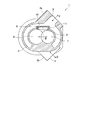
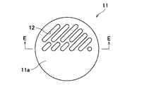
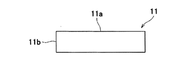
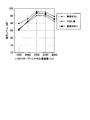
- FIG. 2 is a cross-sectional view taken along the line AA in FIG. It is the side view of the screw compressor which looked at the screw compressor from the central-axis direction of the suction inlet. It is a top view of a lid member. It is a side view of a lid member. It is EE sectional drawing of FIG. 4A. It is the side view of the screw compressor which looked at the screw compressor from the central-axis direction of the suction inlet. It is a graph which shows the analysis result of a sound pressure level. It is a top view of a screw compressor.
- FIG. 8 is a sectional view taken along line FF in FIG. 7. It is a top view of a lid member. It is a side view of a lid member.
- FIG. 9B is a sectional view taken along line GG in FIG. 9A. It is HH sectional drawing of FIG. It is a side view of a lid member.
- the screw compressor 1 by 1st Embodiment of this invention has the cylindrical casing 2 as shown in FIG.
- the casing 2 is provided with a suction port 3 that sucks fluid such as air into the casing 2 and a discharge port 4 that discharges the compressed fluid from the casing 2.
- the portion of the casing 2 where the suction port 3 is provided is a flange portion 2a to which an upstream pipe (not shown) is connected.
- the part in which the discharge port 4 in the casing 2 was provided becomes the flange part 2b to which the downstream piping which is not shown in figure is connected.
- FIG. 2 which is a cross-sectional view taken along the line AA of FIG. 1, a rotor chamber 5 is formed in the casing 2, and a pair of meshing rotors 6, 7 are contained in the rotor chamber 5. Contained. One of the pair of rotors 6 and 7 is rotated by a drive motor (not shown), and the other is driven to rotate.
- a radial intake port 8 for communicating the rotor chamber 5 and the suction port 3 is formed on the radial side of the pair of rotors 6 and 7.
- an axial side intake port (not shown) that allows the rotor chamber 5 and the suction port 3 to communicate with each other is formed on the axial side of the pair of rotors 6 and 7.
- discharge ports (not shown) for communicating the rotor chamber 5 and the discharge ports 4 are formed on the radial side and the axial side of the pair of rotors 6 and 7, respectively.
- the suction port 3 is provided on the radial side of the pair of rotors 6 and 7 and at a position where the central axis C obliquely intersects the connecting direction B of the pair of rotors 6 and 7.
- the discharge port 4 is provided on the radial side of the pair of rotors 6 and 7 and at a position where the central axis D obliquely intersects the connecting direction B of the pair of rotors 6 and 7.
- the position of the discharge port 4 is not particularly limited.
- the fluid whose flow rate is adjusted by an intake adjustment valve flows into the casing 2 through the upstream pipe connected to the flange portion 2a, and the radial intake port 8 and the axial intake air
- the air is sucked into the rotor chamber 5 from the port.
- the fluid sucked into the rotor chamber 5 is compressed by the rotation of the pair of rotors 6 and 7, and then discharged from the discharge ports on the radial side and the axial side, and passes through the downstream pipe connected to the flange portion 2b. Supplied externally.
- the radial intake port 8 is provided at a position facing the suction port 3. That is, the radial-side intake port 8 has such a configuration so that the pair of rotors 6 and 7 can be inspected by visually observing the pair of rotors 6 and 7 from the suction port 3 through the radial-side intake port 8. In the position.
- the cover member 11 mentioned later is not illustrated.
- the opening shape of the radial side intake port 8 shown in FIG. 3 is a shape in the conventional screw compressor.
- the screw compressor 1 of the present embodiment has a lid member 11 that is detachably attached to the radial-side intake port 8.
- the lid member 11 has a bottomed cylindrical shape as shown in FIG. 4A, which is a top view, FIG. 4B, which is a side view, and FIG. 4C, which is a cross-sectional view taken along line EE in FIG. 4A. It is formed of a steel plate of about 5 mm.
- the lid member 11 has a large number of holes 12 in the upper wall 11a and the side wall 11b.
- the many holes 12 are densely provided in the upper half of the upper wall 11a in the drawing and the upper half of the side wall 11b in the drawing.
- the sum of the opening areas of the large number of holes 12 is equal to or larger than the opening area of the radial-side intake port 8 so that the opening area of the lid member 11 is larger than the opening area of the radial-side intake port 8.
- the lower end portion of the side wall 11b in the drawing is an attachment portion to the radial-side intake port 8, and a screw is formed on the outer peripheral surface of this portion.
- the opening shape of the radial intake port 8 is changed from the illustrated shape to a circle, and a screw is formed on the inner peripheral surface of the opening of the radial intake port 8 in the casing 2. ing.
- the lid member 11 has a suction port in which the screw on the outer peripheral surface of the side wall 11 b is screwed into the screw on the opening of the radial side intake port 8 in the casing 2. From the 3 side, it attaches to the radial side intake port 8 so that attachment or detachment is possible. At this time, the numerous holes 12 of the lid member 11 are located at positions away from the central axis C of the suction port 3.
- FIG. 5 which is a side view of the screw compressor 1 viewed from the direction of the central axis C of the suction port 3, a lid member 11 is attached to the radial side intake port 8, so that the radial side intake port 8 extends from the suction port 3.
- the area that can be viewed directly is reduced.
- noise radiated from the radial side intake port 8 collides with the lid member 11, so that the noise is prevented from going straight toward the suction port 3.
- the As a result it is possible to reduce leakage of direct noise generated during compression to the upstream side through the radial intake port 8. And since fluid distribute
- the lid member 11 can be attached to and detached from the radial side intake port 8, the inspection of the rotors 6 and 7 can be suitably performed through the radial side intake port 8 by removing the lid member 11. .
- noise that is radiated from the radial-side intake port 8 and travels straight toward the suction port 3 is suitably reduced. be able to. Thereby, the noise which leaks to an upstream side via the radial side intake port 8 can be reduced further.
- the opening area of the lid member 11 is set to be equal to or larger than the opening area of the radial-side intake port 8, the change in the cross-sectional area of the path through which the fluid flows can be ignored. Thereby, since drawing resistance does not generate
- the lid member 11 having a large number of holes 12 is detachably attached to the radial-side intake port 8.
- noise radiated from the radial-side intake port 8 collides with the lid member 11, so that the noise is prevented from traveling straight toward the suction port 3.
- circulates through many holes 12 of the cover member 11 attached to the radial side intake port 8 the fall of compression performance can be reduced.
- the lid member 11 can be attached to and detached from the radial side intake port 8, the inspection of the rotors 6 and 7 can be suitably performed through the radial side intake port 8 by removing the lid member 11. . Thereby, the noise which leaks to an upstream side via the radial side intake port 8 can be reduced, without reducing compression performance.
- noise that is radiated from the radial-side intake port 8 and travels straight toward the suction port 3 is suitably reduced. be able to. Thereby, the noise which leaks to an upstream side via the radial side intake port 8 can be reduced further.
- the opening area of the lid member 11 is set to be equal to or larger than the opening area of the radial-side intake port 8, the change in the cross-sectional area of the path through which the fluid flows can be ignored. Thereby, since drawing resistance does not generate
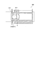
- the screw compressor 201 of the present embodiment is different from the screw compressor 1 of the first embodiment in that the hole 212 of the lid member 211 can be directly viewed from the suction port 3 as shown in FIG. This is a point that is not provided.
- the suction port 3 is the radial side of the pair of rotors 6 and 7, and the central axis C is The pair of rotors 6 and 7 are provided at positions orthogonal to the connecting direction B of the rotors 6 and 7.
- the discharge port 4 is not shown, the position of the discharge port 4 is not particularly limited.
- the opening shape of the radial side intake port 8 is circular, and a screw is formed on the inner peripheral surface of the opening portion of the radial side intake port 8 in the casing 2.
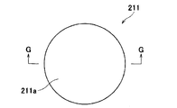
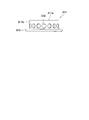
- the lid member 211 has a bottomed cylindrical shape as shown in FIG. 9A, which is a top view, FIG. 9B, which is a side view, and FIG. 9C, which is a GG sectional view of FIG. 9A.
- a number of holes 212 are provided.
- FIG. 9B which is a side view
- many holes 212 are provided over the perimeter of the side wall 211b.
- the hole 212 is not provided in the upper wall 211a.
- the sum of the opening areas of each of the many holes 212 is set to be equal to or larger than the opening area of the radial intake port 8 so that the opening area of the lid member 211 is equal to or larger than the opening area of the radial intake port 8.
- FIG. 4B which is a side view
- the outer peripheral surface of the lower end part in the figure of the side wall 211b is formed with a screw.
- the lid member 211 is configured such that the screw on the outer peripheral surface of the side wall 211 b is screwed into the screw on the opening of the radial side intake port 8 in the casing 2. From the 3 side, it attaches to the radial side intake port 8 so that attachment or detachment is possible. As a result, the radial-side intake port 8 cannot be directly viewed from the suction port 3. Further, the numerous holes 212 of the lid member 211 are located at positions where direct viewing from the suction port 3 is not possible.
- the lid member 211 is detachable from the radial side intake port 8, the rotors 6 and 7 can be suitably inspected via the radial side intake port 8 by removing the lid member 211. .
- the lid member 211 by screwing the lid member 211 into the radial side intake port 8, it is easy to attach and detach, and it is possible to prevent the lid member 211 from being easily detached at the time of mounting.
- the lid member 211 by providing the numerous holes 212 of the lid member 211 at a position where the holes 212 cannot be directly viewed from the suction port 3, it is possible to suitably reduce noise radiated from the radial-side intake port 8 and traveling straight toward the suction port 3. Thereby, the noise which leaks to an upstream side via the radial side intake port 8 can be reduced further.
- the opening area of the lid member 211 is set to be equal to or larger than the opening area of the radial-side intake port 8, the change in the cross-sectional area of the path through which the fluid flows can be ignored. Thereby, since drawing resistance does not generate
- the lid member 311 has a bottomed cylindrical shape as shown in FIG. 11 which is a side view, and has a large number of holes 312 in the side wall 311b. Here, many holes 312 are provided over the entire circumference of the side wall 311b. The hole 312 is not provided in the upper wall 311a. Further, the sum of the opening areas of the multiple holes 312 is equal to or larger than the opening area of the radial intake port 8, so that the opening area of the lid member 311 is larger than the opening area of the radial intake port 8. Has been.
- the lid member 311 has a flange 313 provided with a bolt hole (not shown) at the lower end of the side wall 311b in the drawing.
- the lid member 311 is configured such that the flange 313 abutted against the wall surface forming the rotor chamber 5 of the casing 2 is fixed to the casing 2 with the bolt 314, thereby From the 3 side, it attaches to the radial side intake port 8 so that attachment or detachment is possible.
- the radial-side intake port 8 cannot be directly viewed from the suction port 3.
- the numerous holes 312 of the lid member 311 are located at positions where they cannot be directly viewed from the suction port 3.
- the lid member 311 is fixed to the casing 2 with the bolts 314, it is not necessary to change the shape and area of the radial-side intake port 8 in this embodiment.
- the lid member 311 can be attached to and detached from the radial side intake port 8, the inspection of the rotors 6 and 7 can be suitably performed via the radial side intake port 8 by removing the lid member 311. .
- the lid member 311 can be bolted to the casing 2 and attached to the radial intake port 8 so that the lid member 311 cannot be easily detached during mounting, and the shape and area of the radial intake port 8 can be changed. Can be installed without.
- the lid member 311 by providing the numerous holes 312 of the lid member 311 at a position where the holes 312 cannot be directly viewed from the suction port 3, it is possible to suitably reduce noise radiated from the radial-side intake port 8 and traveling straight toward the suction port 3. Thereby, the noise which leaks to an upstream side via the radial side intake port 8 can be reduced further.
- the opening area of the lid member 311 equal to or larger than the opening area of the radial-side intake port 8
- the change in the cross-sectional area of the path through which the fluid flows can be ignored.
- the lid member 311 is bolted to the casing 2 and attached to the radial-side intake port 8 so that it does not easily come off during installation. Can be attached without changing the shape and area of the radial intake port 8.
Landscapes
- Engineering & Computer Science (AREA)
- Mechanical Engineering (AREA)
- General Engineering & Computer Science (AREA)
- Applications Or Details Of Rotary Compressors (AREA)
Abstract
La présente invention concerne un compresseur à vis qui comprime un fluide qui a été aspiré depuis un orifice d'aspiration et qui évacue le fluide depuis un orifice d'évacuation, et qui possède une paire de rotors, une chambre de rotors qui reçoit la paire de rotors, et un carter dans lequel un orifice d'admission est formé et qui amène la chambre de rotors et l'orifice d'aspiration à communiquer entre eux. L'orifice d'aspiration est situé sur le côté radial de la paire de rotors, et l'orifice d'admission est situé au niveau d'une position faisant face à l'orifice d'aspiration. Un élément couvercle comportant un grand nombre de trous est fixé amovible à l'orifice d'aspiration.
Applications Claiming Priority (2)
| Application Number | Priority Date | Filing Date | Title |
|---|---|---|---|
| JP2013160597A JP6092736B2 (ja) | 2013-08-01 | 2013-08-01 | スクリュ圧縮機 |
| JP2013-160597 | 2013-08-01 |
Publications (1)
| Publication Number | Publication Date |
|---|---|
| WO2015015964A1 true WO2015015964A1 (fr) | 2015-02-05 |
Family
ID=52431505
Family Applications (1)
| Application Number | Title | Priority Date | Filing Date |
|---|---|---|---|
| PCT/JP2014/067087 Ceased WO2015015964A1 (fr) | 2013-08-01 | 2014-06-26 | Compresseur à vis |
Country Status (2)
| Country | Link |
|---|---|
| JP (1) | JP6092736B2 (fr) |
| WO (1) | WO2015015964A1 (fr) |
Cited By (3)
| Publication number | Priority date | Publication date | Assignee | Title |
|---|---|---|---|---|
| EP3351801A4 (fr) * | 2015-09-15 | 2019-05-08 | Gree Electric Appliances, Inc. of Zhuhai | Compresseur à vis et corps de machine associé |
| CN116480588A (zh) * | 2023-04-18 | 2023-07-25 | 北京通嘉宏瑞科技有限公司 | 定子及真空泵 |
| CN116517833A (zh) * | 2023-04-13 | 2023-08-01 | 北京通嘉宏瑞科技有限公司 | 真空泵 |
Citations (4)
| Publication number | Priority date | Publication date | Assignee | Title |
|---|---|---|---|---|
| JPS59176490A (ja) * | 1983-03-24 | 1984-10-05 | Toyoda Autom Loom Works Ltd | スクリユ−圧縮機 |
| JPH07332273A (ja) * | 1994-06-08 | 1995-12-22 | Tochigi Fuji Ind Co Ltd | コンプレッサのケーシング構造 |
| JP2642484B2 (ja) * | 1989-07-13 | 1997-08-20 | 株式会社神戸製鋼所 | スクリュ式流体機械 |
| US20130156624A1 (en) * | 2011-12-16 | 2013-06-20 | Neville D. Kapadia | Slide valve for screw compressor |
-
2013
- 2013-08-01 JP JP2013160597A patent/JP6092736B2/ja active Active
-
2014
- 2014-06-26 WO PCT/JP2014/067087 patent/WO2015015964A1/fr not_active Ceased
Patent Citations (4)
| Publication number | Priority date | Publication date | Assignee | Title |
|---|---|---|---|---|
| JPS59176490A (ja) * | 1983-03-24 | 1984-10-05 | Toyoda Autom Loom Works Ltd | スクリユ−圧縮機 |
| JP2642484B2 (ja) * | 1989-07-13 | 1997-08-20 | 株式会社神戸製鋼所 | スクリュ式流体機械 |
| JPH07332273A (ja) * | 1994-06-08 | 1995-12-22 | Tochigi Fuji Ind Co Ltd | コンプレッサのケーシング構造 |
| US20130156624A1 (en) * | 2011-12-16 | 2013-06-20 | Neville D. Kapadia | Slide valve for screw compressor |
Cited By (6)
| Publication number | Priority date | Publication date | Assignee | Title |
|---|---|---|---|---|
| EP3351801A4 (fr) * | 2015-09-15 | 2019-05-08 | Gree Electric Appliances, Inc. of Zhuhai | Compresseur à vis et corps de machine associé |
| US10487834B2 (en) | 2015-09-15 | 2019-11-26 | Gree Electric Appliances, Inc. Of Zhuhai | Screw compressor and a compressor body thereof |
| CN116517833A (zh) * | 2023-04-13 | 2023-08-01 | 北京通嘉宏瑞科技有限公司 | 真空泵 |
| CN116517833B (zh) * | 2023-04-13 | 2024-01-23 | 北京通嘉宏瑞科技有限公司 | 真空泵 |
| CN116480588A (zh) * | 2023-04-18 | 2023-07-25 | 北京通嘉宏瑞科技有限公司 | 定子及真空泵 |
| CN116480588B (zh) * | 2023-04-18 | 2024-02-23 | 北京通嘉宏瑞科技有限公司 | 定子及真空泵 |
Also Published As
| Publication number | Publication date |
|---|---|
| JP2015031193A (ja) | 2015-02-16 |
| JP6092736B2 (ja) | 2017-03-08 |
Similar Documents
| Publication | Publication Date | Title |
|---|---|---|
| JP4532247B2 (ja) | 流体流動エンジン | |
| CN104350282B (zh) | 一体式的往复引水器驱动装置 | |
| TW201807317A (zh) | 真空泵 | |
| JP6092736B2 (ja) | スクリュ圧縮機 | |
| US20160245160A1 (en) | Variable nozzle unit and variable geometry system turbocharger | |
| US9777601B2 (en) | Muffler and muffling device including the same | |
| EP2071192A1 (fr) | Dispositif de prélèvement d'air dans un compresseur de turbomachine | |
| CN107304848A (zh) | 排水阀、亥姆霍兹型共鸣器、及送风系统 | |
| US20130280041A1 (en) | Oil pump | |
| JP6276117B2 (ja) | 圧縮機及び圧縮機の製造方法 | |
| JP7161918B2 (ja) | バキュームポンプ | |
| JP5044105B2 (ja) | 遠心ポンプ用羽根車及びそれを備えた遠心ポンプ | |
| CN104131963B (zh) | 一种用于压缩机的油气分离消声器 | |
| JP5632252B2 (ja) | 負圧ポンプ | |
| CN205714785U (zh) | 一种螺杆压缩机排气气流脉动衰减器及螺杆压缩系统 | |
| JP5484228B2 (ja) | 真空ポンプ装置 | |
| CN106837802B (zh) | 压缩机排气组件以及旋转式压缩机 | |
| CN101163866A (zh) | 压缩机消声器 | |
| JP5526999B2 (ja) | 消音器及び過給機 | |
| JP2011144705A (ja) | オイルポンプ | |
| US20150010420A1 (en) | Oil pump | |
| US8920118B2 (en) | Casing structure | |
| JP6625360B2 (ja) | ポンプ | |
| JP2011236915A (ja) | 遠心ポンプ用羽根車及びそれを備えた遠心ポンプ | |
| JP5285975B2 (ja) | ダイヤフラムポンプ |
Legal Events
| Date | Code | Title | Description |
|---|---|---|---|
| 121 | Ep: the epo has been informed by wipo that ep was designated in this application |
Ref document number: 14832823 Country of ref document: EP Kind code of ref document: A1 |
|
| NENP | Non-entry into the national phase |
Ref country code: DE |
|
| 122 | Ep: pct application non-entry in european phase |
Ref document number: 14832823 Country of ref document: EP Kind code of ref document: A1 |