WO2015015983A1 - 入力状態検出装置 - Google Patents
入力状態検出装置 Download PDFInfo
- Publication number
- WO2015015983A1 WO2015015983A1 PCT/JP2014/067440 JP2014067440W WO2015015983A1 WO 2015015983 A1 WO2015015983 A1 WO 2015015983A1 JP 2014067440 W JP2014067440 W JP 2014067440W WO 2015015983 A1 WO2015015983 A1 WO 2015015983A1
- Authority
- WO
- WIPO (PCT)
- Prior art keywords
- state
- detection
- mode
- contact
- input
- Prior art date
- Legal status (The legal status is an assumption and is not a legal conclusion. Google has not performed a legal analysis and makes no representation as to the accuracy of the status listed.)
- Ceased
Links
Images




Classifications
-
- G—PHYSICS
- G06—COMPUTING OR CALCULATING; COUNTING
- G06F—ELECTRIC DIGITAL DATA PROCESSING
- G06F3/00—Input arrangements for transferring data to be processed into a form capable of being handled by the computer; Output arrangements for transferring data from processing unit to output unit, e.g. interface arrangements
- G06F3/01—Input arrangements or combined input and output arrangements for interaction between user and computer
- G06F3/03—Arrangements for converting the position or the displacement of a member into a coded form
- G06F3/041—Digitisers, e.g. for touch screens or touch pads, characterised by the transducing means
- G06F3/0416—Control or interface arrangements specially adapted for digitisers
- G06F3/0418—Control or interface arrangements specially adapted for digitisers for error correction or compensation, e.g. based on parallax, calibration or alignment
-
- G—PHYSICS
- G06—COMPUTING OR CALCULATING; COUNTING
- G06F—ELECTRIC DIGITAL DATA PROCESSING
- G06F1/00—Details not covered by groups G06F3/00 - G06F13/00 and G06F21/00
- G06F1/26—Power supply means, e.g. regulation thereof
- G06F1/32—Means for saving power
- G06F1/3203—Power management, i.e. event-based initiation of a power-saving mode
- G06F1/3234—Power saving characterised by the action undertaken
- G06F1/325—Power saving in peripheral device
- G06F1/3262—Power saving in digitizer or tablet
-
- G—PHYSICS
- G06—COMPUTING OR CALCULATING; COUNTING
- G06F—ELECTRIC DIGITAL DATA PROCESSING
- G06F3/00—Input arrangements for transferring data to be processed into a form capable of being handled by the computer; Output arrangements for transferring data from processing unit to output unit, e.g. interface arrangements
- G06F3/01—Input arrangements or combined input and output arrangements for interaction between user and computer
- G06F3/03—Arrangements for converting the position or the displacement of a member into a coded form
- G06F3/041—Digitisers, e.g. for touch screens or touch pads, characterised by the transducing means
- G06F3/0416—Control or interface arrangements specially adapted for digitisers
-
- G—PHYSICS
- G06—COMPUTING OR CALCULATING; COUNTING
- G06F—ELECTRIC DIGITAL DATA PROCESSING
- G06F3/00—Input arrangements for transferring data to be processed into a form capable of being handled by the computer; Output arrangements for transferring data from processing unit to output unit, e.g. interface arrangements
- G06F3/01—Input arrangements or combined input and output arrangements for interaction between user and computer
- G06F3/03—Arrangements for converting the position or the displacement of a member into a coded form
- G06F3/041—Digitisers, e.g. for touch screens or touch pads, characterised by the transducing means
- G06F3/044—Digitisers, e.g. for touch screens or touch pads, characterised by the transducing means by capacitive means
- G06F3/0445—Digitisers, e.g. for touch screens or touch pads, characterised by the transducing means by capacitive means using two or more layers of sensing electrodes, e.g. using two layers of electrodes separated by a dielectric layer
-
- H—ELECTRICITY
- H03—ELECTRONIC CIRCUITRY
- H03K—PULSE TECHNIQUE
- H03K17/00—Electronic switching or gating, i.e. not by contact-making and –breaking
- H03K17/94—Electronic switching or gating, i.e. not by contact-making and –breaking characterised by the way in which the control signals are generated
- H03K17/96—Touch switches
- H03K17/962—Capacitive touch switches
-
- G—PHYSICS
- G06—COMPUTING OR CALCULATING; COUNTING
- G06F—ELECTRIC DIGITAL DATA PROCESSING
- G06F2203/00—Indexing scheme relating to G06F3/00 - G06F3/048
- G06F2203/041—Indexing scheme relating to G06F3/041 - G06F3/045
- G06F2203/04101—2.5D-digitiser, i.e. digitiser detecting the X/Y position of the input means, finger or stylus, also when it does not touch, but is proximate to the digitiser's interaction surface and also measures the distance of the input means within a short range in the Z direction, possibly with a separate measurement setup
Definitions
- the present invention relates to an input state detection device that detects that a conductive object such as a human finger has come into contact and is pressed by the object.
- Patent Document 1 describes an apparatus that can detect an approaching state and a pressing state of a human finger by using a capacitive sensor.
- the variable capacitance increases.
- the first electrode is pressed by the finger through the insulating sheet, the variable capacitance increases when the first electrode and the second electrode approach each other. .
- detection of touching with a finger and detection of pressing with a finger are performed. .
- the detected potential or current is the change in the potential or current on the first electrode side and the potential on the second electrode side. Or affected by changes in current. Therefore, the detected potential or current may become unstable depending on the magnitude of the pressing force.
- This invention is made in view of such a situation, and it aims at providing the input state detection apparatus which can detect the contact and pressing state of a target object reliably.
- the present inventors use a constant voltage power supply device, and a capacitive sensor is interposed between the application terminal of the constant voltage power supply device and the detection terminal of the detector.
- the detector was connected in series with the capacitive sensor.
- a circuit in which the object contacts the electrode on the detection terminal side of the detector, that is, the electrode on the opposite side of the application terminal of the constant voltage power supply device is pressed by the object.
- the circuit is such that the object presses the electrode on the opposite side of the detection terminal of the detector, that is, the electrode on the application terminal side of the constant voltage power supply device. That is, the positional relationship between the object and the electrode of the capacitive sensor is opposite to the circuit configuration of the present invention and the circuit configuration described in Patent Document 1. Below, the detail of this means is demonstrated.
- An input state detection device is arranged between a first electrode attached to a base material, a second electrode located on the side of a conductive object to be contacted, and the first electrode and the second electrode.
- a capacitive sensor comprising a dielectric layer that is compressed by a pressing force applied to the second electrode by the object, an application terminal is connected to the capacitive sensor side, and the capacitive type
- a constant voltage power supply device that applies a predetermined voltage to the sensor, and the capacitance type sensor connected in series, a detection terminal is connected to the capacitance type sensor side, and the capacitance of the capacitance type sensor
- a detector that detects a potential at the detection terminal that changes according to a capacitance of the object or a current that flows from the detection terminal, and an application terminal of the constant voltage power supply device is connected to the first electrode side, And the detection terminal of the detector A first state connected to the second electrode side, a second state where the application terminal of the constant voltage power supply device is connected to the second electrode side, and
- the input detection unit detects whether the object is in a non-contact state or a contact non-pressing state in the first state.
- the first state is a state in which the application terminal of the constant voltage power supply device is connected to the first electrode side, and the detection terminal of the detector is connected to the second electrode side. That is, the object is connected in series to the capacitive sensor and connected in parallel to the detector. In this case, due to the contact of the conductive object, the current flowing through the circuit is branched from the capacitive sensor into a path on the detector side and a path on the object side. Therefore, the detection value of the detector is surely reduced with the contact of the object. Thereby, the non-contact state and the contact non-pressing state of the object can be reliably determined.
- the input detection unit detects whether the object is in a non-contact pressing state or a pressing state in the second state.
- the second state is a state in which the application terminal of the constant voltage power supply device is connected to the second electrode side, and the detection terminal of the detector is connected to the first electrode side. That is, the object is connected in parallel to the capacitance type sensor and the detector.
- the current flowing through the circuit is branched from the constant voltage power supply device into a path on the capacitive sensor and detector side and a path on the object side by pressing the conductive object.
- the voltage applied to the capacitance type sensor and the detector becomes a voltage by the constant voltage power supply device regardless of the pressing by the object due to the parallel connection. Therefore, the detection value of the detector increases as the capacitance of the capacitance type sensor increases due to the pressing of the object. Thereby, the contact non-pressing state and the pressing state of the object can be reliably determined.
- the predetermined voltage applied by the constant voltage power supply device is a periodic voltage
- the detector corresponds to a capacitance of the capacitance sensor and a capacitance of the object. It is an ammeter that detects a current flowing from the detection terminal as a value.
- the current detected by the ammeter has a value corresponding to the capacitance of the capacitance type sensor and the capacitance of the object. Therefore, the non-contact state, the contact non-pressing state, and the pressing state of the object can be determined using the current detected by the ammeter.
- the detector can use the following circuit. That is, the detector is connected in parallel to the bridge capacitor connected between the detection terminal of the detector and the ground potential, and to the bridge capacitor, and the charge of the detection terminal is grounded in the closed state.
- a charging / discharging switching element that discharges to a potential; and a step of discharging the charge of the detection terminal to a ground potential in a state in which the constant voltage power supply device does not apply the predetermined voltage to the capacitive sensor; And after the step of discharging, charging the capacitive sensor by opening the charging / discharging switching element and applying the predetermined voltage by the constant voltage power supply device.
- the capacitance of the capacitive sensor and the target As the electrostatic value corresponding to the capacitance, the potential detector for detecting a potential of the detection terminals may be provided with.
- the potential of the detection terminal detected by the thus configured detector is a value corresponding to the capacitance of the capacitance sensor and the capacitance of the object. Therefore, it is possible to determine the non-contact state, the contact non-pressing state, and the pressing state of the object using the potential detected by the detector.
- the input detection unit detects the magnitude of the pressing force applied to the second electrode by the object based on the detection value of the detector in the second state.
- the potential at the detection terminal or the current flowing from the detection terminal is substantially affected by the capacitance of the capacitive sensor. Therefore, in the second state, the equivalent value of the capacitance of the capacitance type sensor can be detected based on the detection value of the detector.
- the electrostatic capacitance of an electrostatic capacitance type sensor is corresponded to the magnitude
- the input state detection device includes a control unit that controls a state of the state switching unit, and the control unit periodically switches the state switching unit between the first state and the second state.
- the switching and the input detection unit periodically perform detection of the non-contact state or the contact non-pressing state and detection of the contact non-pressing state or the pressing state. That is, since the detection in the first state and the detection in the second state are alternately performed, the pressing state of the object can be detected at an early stage. Moreover, the change from the pressing state to the second electrode to the non-contact state can be detected at an early stage.
- a mode in which the state switching unit continues the first state is a first mode
- a mode in which the state switching unit continues the second state is a second mode
- the state switching unit has the first mode.
- a mode in which one state and the second state are periodically switched alternately is a third mode
- the input state detection device includes a control unit that controls the mode of the state switching unit.
- the control unit switches the state switching unit from the first mode to the third mode when changing from the non-contact state to the contact non-pressing state, and changes from the contact non-pressing state to the non-contact state.
- the state switching unit is switched from the third mode to the first mode, and when the contact non-pressing state is changed to the pressing state, the state switching unit is changed from the third mode to the second mode.
- the state switching unit is switched from the second mode to the third mode.
- the input detection unit when the state switching unit is set to the first mode in which the first state is maintained in the non-contact state, the input detection unit reliably changes from the non-contact state to the contact non-pressing state. It can be detected.
- the state switching unit when detecting the magnitude of the pressing force, when the pressing state is set, the state switching unit is set to the second mode in which the second state is continued, so that the input detecting unit can accurately determine the pressing force level. Can be detected.
- the third mode is a mode in which the first state and the second state are alternately switched periodically. That is, in the third mode, the state switching unit smoothly transitions to the first mode that continues the first state, and also smoothly transitions to the second mode that continues the second state.
- the input detection unit changes from the non-contact state to the contact non-pressing state when a detection value of the detector in the first state is lower than a first threshold value in the first mode. Determining that the detection value of the detector in the first state exceeds the first threshold value in the third mode, so that the contact non-pressing state is changed to the non-contact state, and the third mode is determined. It is determined that the detection value of the detector in the second state is changed from the contact non-pressing state to the pressing state by exceeding a second threshold, and the second state is the second state in the second state.
- the control unit is based on the determination by the input detection unit, the non-contact state, It acquires serial contact changes in non-pressing state and the pressing conditions.
- the input detection unit can reliably determine the change in the state of the object by using the first threshold value or the second threshold value in each mode. Therefore, the control unit can appropriately switch between the modes.
- the difference between the detection value of the detector in the first state and the first threshold value in the contact non-pressing state is the detector in the second state in the contact non-pressing state.
- the first threshold value and the second threshold value are set to be larger than the difference between the detected value and the second threshold value.
- control unit makes it possible for the control unit to reliably determine whether it has changed to the non-contact state or the pressing state when in the contact non-pressing state. As a result, the control unit can further reliably determine whether to switch to the first mode or to switch to the second mode in the third mode.
- the mode in which the state switching unit continues the first state is a first mode
- the mode in which the state switching unit continues the second state is a second mode
- the input state detection device is A control unit that controls the state of the state switching unit; and the control unit changes the state switching unit from the first mode to the second mode when the non-contact state changes to the contact non-pressing state.
- the state switching unit is switched from the second mode to the first mode.
- the non-contact state, the contact non-pressing state, and the pressing state of the object can be detected.
- the number of switching operations by the state switching unit can be reduced, and energy consumption can be reduced.
- a plurality of capacitance-type sensors are configured by providing a plurality of at least one of the first electrode and the second electrode, and the input detection unit is a position where the object exists. Is detected. Thereby, the position which the target object is contacting or pressing can be detected.
- the dielectric layer is formed of an elastomer or a resin.
- the first electrode and the second electrode are formed by blending an elastomer with a conductive filler. By forming the first electrode and the second electrode as described above, the first electrode and the second electrode have flexibility and can be stretched and contracted.
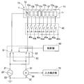
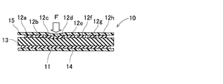
- FIG. 2 is a cross-sectional view of the capacitive sensor unit of FIG. 1.
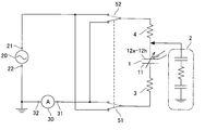
- the equivalent circuit of an input state detection apparatus is shown.
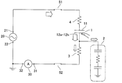
- the equivalent circuit of the input state detection apparatus in a 1st state is shown.
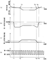
- the equivalent circuit of the input state detection apparatus in a 2nd state is shown. It is a timing chart in 1st embodiment, Comprising: (a) shows the position of a human finger which is a subject, (b) shows the detected value by the ammeter in the 1st state, (c) is the 2nd state The detection value by the ammeter is shown, and (d) shows the switching timing by the control unit.
- the structure of the input state detection apparatus of 2nd embodiment is shown.
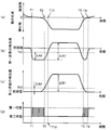
- the switching timing by the control part in 2nd embodiment is shown.
- T1 to T4 are common to FIG.
- the switching timing by the control part in 3rd embodiment is shown.
- T1 to T4 are common to FIG.
- the structure of the input state detection apparatus of 4th embodiment is shown.
- the structure of the input state detection apparatus of 5th embodiment is shown.
- toe which is a target object is a non-contact state with respect to an electrostatic capacitance type sensor is shown.
- FIG. 10 is a timing chart of operations of the switching elements SW10 and SW11 and one potential Vin1 and the output potential Vout of the capacitive sensor in the fifth embodiment.
- toe which is a target object is a contact non-pressing state with respect to a capacitance type sensor in a 1st state is shown.
- toe which is a target object is a pressing state with respect to an electrostatic capacitance type sensor in a 2nd state is shown.
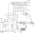
- the input state detection apparatus includes a capacitive sensor unit 10 and detects that a conductive object has come into contact with the sensor unit 10 and has pressed the sensor unit 10.
- the conductive object detects, as a human finger, that the human finger has touched the sensor unit 10 and that the sensor unit 10 has been pressed by the human finger.
- the input state detection device can also detect the pressing force.
- the input state detection device includes the capacitive sensor unit 10 as described above. First, the capacitive sensor unit 10 will be described with reference to FIGS. 1 and 2.
- the capacitive sensor unit 10 constitutes a plurality of capacitive sensors 1 to be described later. However, the capacitive sensor unit 10 may constitute one capacitive sensor 1.
- the capacitive sensor unit 10 of the present embodiment includes a base material 14, a first electrode 11, a plurality of second electrodes 12a to 12h, a dielectric layer 13, and a skin.
- Layer 15 As shown in FIG. 2, the base material 14 is formed of a nonconductive resin or the like, and is located on the back surface side of the capacitive sensor unit 10.
- the 1st electrode 11 is attached to the surface side of the base material 14, as shown in FIG. As shown in FIG. 1, the first electrode 11 is formed in a band shape.
- the plurality of second electrodes 12a to 12h are provided to face the first electrode 11 with a distance in the surface normal direction. That is, the plurality of second electrodes 12a to 12h are positioned on the side of the conductive object that comes into contact with the first electrode 11. Further, as shown in FIG. 1, each of the plurality of second electrodes 12a to 12h is formed in a strip shape and arranged in parallel to each other. Here, the plurality of second electrodes 12 a to 12 h are arranged side by side with respect to the extending direction of the first electrode 11.
- the positions where the first electrode 11 and the plurality of second electrodes 12a to 12h face each other are arranged in a line.
- eight opposing positions are arranged in a line in the capacitive sensor unit 10.
- each of the electrodes 11, 12a to 12h is formed by, for example, blending a conductive filler in an elastomer.
- each of the electrodes 11, 12 a to 12 h can have a flexible and stretchable property.
- the elastomer constituting each of the electrodes 11, 12a to 12h include silicone rubber, ethylene-propylene copolymer rubber, natural rubber, styrene-butadiene copolymer rubber, acrylonitrile-butadiene copolymer rubber, acrylic rubber, epichlorohydrin rubber, Chlorosulfonated polyethylene, chlorinated polyethylene, urethane rubber and the like can be applied.
- the conductive filler blended in each of the electrodes 11, 12a to 12h may be any particle having conductivity, and for example, fine particles such as carbon materials and metals can be applied.
- the dielectric layer 13 is disposed between the first electrode 11 and each of the plurality of second electrodes 12a to 12h, and the plurality of second electrodes 12a in the capacitive sensor unit 10. Compressed by the pressing force of a human finger on the surface on the 12h side.
- the dielectric layer 13 is formed of an elastomer or a resin and has flexibility similar to the first and second electrodes 11 and 12a to 12h.
- the elastomer constituting the dielectric layer 13 include silicone rubber, acrylonitrile-butadiene copolymer rubber, acrylic rubber, epichlorohydrin rubber, chlorosulfonated polyethylene, chlorinated polyethylene, and urethane rubber.
- the resin constituting the dielectric layer 13 examples include polyethylene resin, polypropylene resin, polyurethane resin, polystyrene resin (including crosslinked foamed polystyrene resin), polyvinyl chloride-polyvinylidene chloride copolymer, and ethylene-acetic acid copolymer. Coalescence etc. can be applied. More preferably, the dielectric layer 13 is preferably an elastomer capable of large elastic deformation during compression. This is because a large compressive deformation induces a large capacitance change.
- the skin layer 15 is arranged so as to cover the surface sides of the plurality of second electrodes 12a to 12h.
- the skin layer 15 is formed of a non-conductive material and has flexibility and a stretchable property. That is, when the skin layer 15 (corresponding to the “surface on the second electrode side in the capacitive sensor”) is pressed by a human finger and the dielectric layer 13 is compressed and deformed, the skin layer 15 is deformed by the deformation of the dielectric layer 13. Can be followed.
- the skin layer 15 is formed of, for example, a material described as an elastomer or a resin constituting the dielectric layer 13.
- the capacitance type sensor unit 10 configured as described above is configured so that the first electrode 11 and each of the plurality of second electrodes 12a to 12h are opposed to each other at eight positions arranged in a line. .
- one capacitive sensor 1 (see FIG. 3) is formed by the first electrode 11 constituting the facing position, any of the plurality of second electrodes 12a to 12h, and the dielectric layer 13 interposed therebetween. Form). That is, the capacitive sensor unit 10 includes eight capacitive sensors 1.
- the dielectric layer 13 When the skin layer 15 is pressed with a pressing force F in the surface normal direction of the capacitive sensor unit 10 by a human finger, the dielectric layer 13 is compressed and deformed in the surface normal direction. The distance between the electrodes constituting the capacitive sensor 1 located in the part is shortened. As a result, the capacitance of the capacitive sensor 1 located at the site increases. On the other hand, when the human finger is in contact with the skin layer 15 but is not pressed, the dielectric layer 13 is not compressed and deformed, and the capacitances of all the capacitive sensors 1 do not change.
- each of the electrodes 11, 12a to 12h is formed of a material having flexibility and elastic properties as described above. Therefore, each of the electrodes 11, 12a to 12h has a higher resistance than an electrode formed of a simple conductive metal plate or the like. Therefore, for example, when the facing position between the first electrode 11 and the second electrode 12a is the capacitive sensor 1 at the target position, the first electrode 11 and the second electrode 12a up to the target position are It functions as resistors 3 and 4 (shown in FIG. 3) connected in series to the capacitive sensor 1. That is, the capacitive sensor unit 10 includes the capacitive sensor 1 and the resistors 3 and 4 connected in series to both sides thereof.
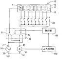
- the input state detection device includes a constant voltage power supply device 20, an ammeter 30, an electrode side switching unit 40, a state switching unit 50, a control unit 60, an input, in addition to the capacitive sensor unit 10.
- a detection unit 70 is provided.
- the constant voltage power supply device 20 is a power source that connects the application terminal 21 to the capacitive sensor 1 side and applies a periodic voltage (AC voltage, rectangular wave voltage, etc.) to the capacitive sensor 1. .
- the ground terminal 22 of the constant voltage power supply device 20 is connected to the ground potential.
- the ammeter 30 (detector) is connected in series to the capacitive sensor 1.
- the detection terminal 31 of the ammeter 30 is connected to the capacitive sensor 1 side
- the ground terminal 32 of the ammeter 30 is connected to the ground potential side. That is, the capacitive sensor 1 is connected between the application terminal 21 of the constant voltage power supply device 20 and the detection terminal 31 of the ammeter 30.
- the ground terminal 32 of the ammeter 30 is connected to the ground terminal 22 of the constant voltage power supply device 20.
- the ammeter 30 detects the current flowing from the detection terminal 31.
- the current detected by the ammeter 30 changes in accordance with the capacitance of the capacitive sensor 1 and the capacitance of the human finger that is the object.
- the electrode-side switching unit 40 includes switches 40a to 40h, and a switch connected to one of the second electrodes 12a to 12h set in advance according to each measurement target is closed (ON). The remaining switches are opened (OFF). In FIG. 1, when the electrostatic capacitance sensor 1 with hatching is set as a measurement target, the switch 40a connected to the second electrode 12a is closed, and the remaining switches 40b to 40h are opened. Yes.
- the state switching unit 50 includes a first switch 51 and a second switch 52.
- One end of the first switch 51 is connected to the first electrode 11.
- the other end of the first switch 51 can selectively switch between connection to the application terminal 21 of the constant voltage power supply device 20 and connection to the detection terminal 31 of the ammeter 30.
- One end of the second switch 52 is connected to the second electrodes 12a to 12h via the electrode side switching unit 40.
- the other end of the second switch 52 can be selectively switched between connection to the application terminal 21 of the constant voltage power supply device 20 and connection to the detection terminal 31 of the ammeter 30.
- the switching operation of the first and second switches 51 and 52 of the state switching unit 50 is controlled by the control unit 60.
- the control unit 60 controls the first switch 51 and the second switch 52 to operate in conjunction with each other. Specifically, when the first switch 51 is connected to the application terminal 21 side of the constant voltage power supply device 20, the second switch 52 is connected to the detection terminal 31 side of the ammeter 30. On the other hand, when the first switch 51 is connected to the detection terminal 31 side of the ammeter 30, the second switch 52 is connected to the application terminal 21 side of the constant voltage power supply device 20. That is, the control unit 60 causes one of the application terminal 21 of the constant voltage power supply device 20 and the detection terminal 31 of the ammeter 30 to be connected to the first electrode 11, and the other is selected from the second electrodes 12a to 12h. To be connected to any of the above.
- the state in which the first switch 51 is connected to the application terminal 21 side of the constant voltage power supply device 20 and the second switch 52 is connected to the detection terminal 31 side of the ammeter 30 is referred to as a first state.
- a state in which the first switch 51 is connected to the detection terminal 31 side of the ammeter 30 and the second switch 52 is connected to the application terminal 21 side of the constant voltage power supply device 20 is referred to as a second state.
- the state switching unit 50 connects the application terminal 21 of the constant voltage power supply device 20 to the first electrode 11 side, and connects the detection terminal 31 of the ammeter 30 to the second electrodes 12a to 12h side. And a second state in which the application terminal 21 of the constant voltage power supply device 20 is connected to the second electrodes 12a to 12h side, and the detection terminal 31 of the ammeter 30 is connected to the first electrode 11 side. .
- the input detection unit 70 is in contact with the surface of the capacitive sensor unit 10 on the second electrodes 12 a to 12 h side and a non-pressing state (hereinafter, referred to as “human finger”). , Referred to as “contact non-pressing state”). That is, the input detection unit 70 detects whether a human finger is in a non-contact state or a contact non-pressing state with respect to the capacitive sensor unit 10. Further, the input detection unit 70 detects based on the detection value of the ammeter 30 that a human finger, which is an object, has applied a pressing force to the capacitive sensor unit 10. That is, the input detection unit 70 detects whether a human finger is in a non-contact pressing state or a pressing state with respect to the capacitive sensor unit 10.
- the input detection unit 70 detects whether a human finger as a target object is in a non-contact state or a contact non-pressing state based on a detection value of the ammeter 30 in the first state. To do. Moreover, the input detection part 70 detects whether the human finger
- FIG. 3 shows an equivalent circuit when an arbitrary capacitive sensor 1 of the capacitive sensor unit 10 is a measurement target.
- the capacitive sensor 1 is variable, a resistor 3 is connected in series on the first electrode 11 side of the capacitive sensor 1, and the second electrodes 12a to 12h of the capacitive sensor 1 are connected.
- a resistor 4 is connected in series on the side.
- the application terminal 21 of the constant voltage power supply device 20 is connected to the first electrode 11 side of the capacitive sensor 1 and the detection terminal of the ammeter 30 is detected.
- 31 is connected in series to the second electrodes 12 a to 12 h side of the capacitive sensor 1.
- the application terminal 21 of the constant voltage power supply device 20 is connected to the second electrodes 12a to 12h side of the capacitive sensor 1, and the ammeter 30
- the detection terminal 31 is connected in series to the first electrode 11 side of the capacitive sensor 1.
- the human finger 2 As shown by a two-dot chain line frame in FIG. 3, the human finger 2 is represented by a series circuit of a capacitor of 2200 pF, a resistance of 1 to 10 k ⁇ , and a capacitor of 100 pF, for example. That is, the equivalent circuit of the object is connected to the second electrodes 12a to 12h in a state where the human finger 2 is in contact with the skin layer 15 or in a state where the skin layer 15 is pressed.
- the current supplied by the constant voltage power supply device 20 passes through the capacitive sensor 1 and then branches into a path on the side of the ammeter 30 and the resistor 4 and a path on the equivalent circuit side of the human finger 2. Is done. Accordingly, at the moment when current flows from the second electrodes 12a to 12h to the human finger 2 side, the current flowing through the ammeter 30 decreases.
- the finger 2 at the moment when the current flows from the second electrodes 12a to 12h to the human finger 2 side, the finger 2 must be electrically connected between the second electrodes 12a to 12h and the resistor 4, and substantially Specifically, it is equal to the moment when the human finger 2 contacts the epidermis layer 15.
- the input detection unit 70 detects whether the human finger 2 is in a non-contact state or a contact non-pressing state with respect to the skin layer 15 based on a detection value by the ammeter 30 in the first state. To do.
- the detection value by the ammeter 30 in the first state is used to detect whether or not the human finger 2 is in contact with the epidermis layer 15, but detects whether or not the human finger has applied a pressing force. Do not use to do.
- the current supplied by the constant voltage power supply device 20 is branched into a path on the capacitive sensor 1, resistor 3 and ammeter 30 side, and a path on the equivalent circuit side of the human finger 2.
- the capacitive sensor 1 and the human finger 2 are connected in parallel, so that the amount of current flowing through the path on the equivalent circuit side of the human finger 2 is reduced.
- the constant voltage power supply 20 supplies the current so that the current flowing through the path on the capacitive sensor 1 side is approximately the same as the original magnitude. Therefore, even if the human finger 2 is in contact with the skin layer 15 in the second state, the current flowing through the path on the capacitive sensor 1 side is hardly affected.
- the capacitance of the capacitive sensor 1 changes. Specifically, the capacitance changes as the pressing force increases. That is, when the capacitance of the capacitive sensor 1 increases, the current flowing through the path on the capacitive sensor 1, resistor 3, and ammeter 30 side increases. That is, the detected value of the ammeter 30 increases as the pressing force increases in the second state.
- the input detection unit 70 detects whether or not the human finger 2 has applied a pressing force to the epidermis layer 15 based on the value detected by the ammeter 30 in the second state. That is, the input detection unit 70 detects whether the human finger is in a non-contacting state or a pressing state against the skin layer 15 in the second state. Further, the input detection unit 70 detects the magnitude of the pressing force applied to the skin layer 15.
- the value detected by the ammeter 30 in the second state is used to detect whether or not the human finger 2 has applied a pressing force to the epidermis layer 15, but to detect whether or not it has touched. Not used for.
- FIG. 6A shows the position of the tip of the human finger 2.
- the human finger 2 approaches the skin layer 15 of the capacitive sensor unit 10 (before time T1) and contacts the skin layer 15 (time T1-T2), the skin layer 15 is pressed (time T2-T3). ), And then the skin layer 15 is in a non-contact state (after time T4).
- the current flowing through the ammeter 30 exhibits the behavior shown in FIG. 6B
- the current flowing through the ammeter 30 exhibits the behavior shown in FIG. 6C.
- FIG. 6B shows the current flowing through the ammeter 30 when the first state is continued.
- FIG. 6C shows a current flowing through the ammeter 30 when the second state is continued. Therefore, FIGS. 6B and 6C are not currents actually detected by the ammeter 30.
- the detection value of the ammeter 30 in the first state decreases at the moment when the human finger 2 comes into contact with the epidermis layer 15 from the non-contact state as shown in FIG. It increases slightly by applying force, decreases slightly at the moment when the pressing state changes to the non-contacting state, and increases to return to the initial value again from the non-contacting state to the non-contacting state.
- the detection value of the ammeter 30 in the second state hardly changes when the human finger 2 is in a non-contact state and a non-contact pressing state with respect to the epidermis layer 15 as shown in FIG. Therefore, the detection value of the ammeter 30 at this time is defined as a reference value.
- the value detected by the ammeter 30 increases as the pressing force increases.
- the difference between the detection value by the ammeter 30 and the reference value corresponds to the magnitude of the pressing force.
- the detection value by the ammeter 30 returns to the initial value (corresponding to the reference value).
- the control unit 60 performs the switching timing of the switches 51 and 52 of the state switching unit 50 as follows.
- the switching timing of the switches 51 and 52 is performed as shown in FIG. That is, the control unit 60 periodically switches the switches 51 and 52 of the state switching unit 50 between the first state and the second state.
- the period is set to a time sufficiently shorter than the average time from when the human finger 2 comes into contact with the epidermis layer 15 until it becomes non-contact.
- the input detection unit 70 detects whether the human finger 2 that is the object in the first state is in a non-contact state or a contact non-pressing state with respect to the skin layer 15, and contacts in the second state. The detection of the non-pressing state or the pressing state is periodically performed. Of course, in the second state, the input detection unit 70 also detects the magnitude of the pressing force.
- the input detection unit 70 determines that the detection value by the ammeter 30 is lower than the first threshold value Th1 in the first state, so that the human finger 2 is applied to the epidermis layer 15. Detects a change from a non-contact state to a contact non-pressing state. In FIG. 6D, the input detection unit 70 detects that the human finger 2 has contacted the epidermis layer 15 in the first state slightly after the time T1.
- the input detection unit 70 determines that the detection value by the ammeter 30 exceeds the second threshold Th2 in the second state, so that the human finger 2 is not pressed against the skin layer 15 in a non-contact manner. Detects a change from the state to the pressing state. In FIG. 6D, since it is in the second state at time T2, at time T2, the input detection unit 70 detects that the human finger 2 applied a pressing force to the epidermis layer 15. Furthermore, the input detection unit 70 also detects the magnitude of the pressing force in the second state.
- the input detection unit 70 determines that the detection value of the ammeter 30 is lower than the second threshold Th2 in the second state, so that the human finger 2 is pressed from the pressed state against the epidermis layer 15. Detects a change to the non-pressing state. In FIG. 6D, the input detection unit 70 detects that the human finger 2 has released the pressing force against the epidermis layer 15 around time T3.
- the input detection unit 70 determines that the detection value by the ammeter 30 exceeds the first threshold value Th1 in the first state, so that the human finger 2 is not pressed against the skin layer 15 in a non-contact manner. Detects a change from a state to a non-contact state. In FIG. 6D, in the first state slightly after time T4, the input detection unit 70 detects that the human finger 2 is in a non-contact state from the epidermis layer 15.
- the pressing state of the human finger 2 can be detected at an early stage. Further, it is possible to detect at an early stage that the human finger 2 is separated from the second electrodes 12a to 12h from the pressed state against the second electrodes 12a to 12h.
- the input state detection device of the second embodiment will be described with reference to FIGS.
- the input state detection device of this embodiment is different from the input state detection device of the first embodiment in a control unit 160 and an input detection unit 170.
- Other configurations are denoted by the same reference numerals and description thereof is omitted.
- the control unit 160 acquires the non-contact state, the contact non-pressing state, and the change in the pressing state based on the determination by the input detection unit 170. Then, the control unit 160 controls the switching operation of the first and second switches 51 and 52 of the state switching unit 50 based on the information acquired from the input detection unit 170.
- the state switching unit 50 is set to one of the following first mode, second mode, and third mode by the control unit 160.
- the first mode is a mode in which the state switching unit 50 continues the first state.
- the second mode is a mode in which the state switching unit 50 continues the second state.
- the third mode is a mode in which the state switching unit 50 periodically and alternately switches between the first state and the second state.
- the detected value (minimum value of T1 to T2) of the ammeter 30 in the first state when the contact is not pressed and the current in the first state when the button is pressed is ⁇ A1.
- the difference between the detected value of the ammeter 30 in the first state in the non-contact pressing state (minimum value of T1 to T2) and the first threshold Th1 is ⁇ A2.
- the detected value (minimum value of T1 to T2) of the ammeter 30 in the second state when the contact is not pressed and the ammeter in the second state when the button is pressed is ⁇ B1.
- the difference between the detected value of the ammeter 30 in the second state in the non-pressing state (minimum value of T1 to T2) and the second threshold Th2 is ⁇ B2.
- the first threshold value Th1 and the second threshold value Th2 are set so as to satisfy the relationship of Expression (1). That is, the first threshold Th1 and the second threshold Th2 are set so that the ratio of ⁇ A2 to ⁇ A1 is larger than the ratio of ⁇ B2 to ⁇ B1.
- the detection value of the ammeter 30 in the second state exceeds the second threshold value Th2 when the contact non-pressing state is changed to the pressing state
- the detection value of the ammeter 30 in the first state is the first threshold value Th1. It is ahead of the time exceeding.
- the first threshold value Th1 and the second threshold value Th2 are simply set as follows. That is, the difference ⁇ A2 between the detected value of the ammeter 30 in the first state when the contact is not pressed and the first threshold Th1 is equal to the detected value of the ammeter 30 in the second state when the contact is not pressed.
- the first threshold Th1 and the second threshold Th2 are set so as to be larger than the difference ⁇ B2 from the threshold Th2.
- the control unit 160 sets the state switching unit 50 as the initial state, that is, when the input detection unit 170 determines that it is in the non-contact state.
- One mode the input detection unit 170 determines that the detection value of the ammeter 30 in the first state changes from the non-contact state to the contact non-pressing state because the detection value is lower than the first threshold Th1. Therefore, as can be seen from FIG. 8B, the input detection unit 170 determines that the non-contact state has changed to the non-contact pressing state at time T1.
- the control unit 160 switches the state switching unit 50 from the first mode to the third mode at time T1. That is, the state switching unit 50 is periodically switched between the first state and the second state alternately.
- the input detection unit 170 detects whether the contact non-pressing state is changed to the pressing state, or whether the contact non-pressing state is changed to the non-contact state.
- the first threshold value Th1 and the second threshold value Th2 are set so as to satisfy the expression (1) as described above. Therefore, when the change from the non-contact pressing state to the pressing state occurs, the time T2 when the detected value of the ammeter 30 in the second state exceeds the second threshold Th2 indicates that the detected value of the ammeter 30 in the first state is the first threshold. It is ahead of time T10 exceeding Th1. Then, the input detection unit 170 determines that the detected value of the ammeter 30 in the second state changes from the contact non-pressing state to the pressing state when the detection value of the ammeter 30 in the second state exceeds the second threshold Th2. Therefore, as can be seen from FIG. 8C, the input detection unit 170 determines that the contact non-pressing state has changed to the pressing state at time T2.
- the control unit 160 switches the state switching unit 50 from the third mode to the second mode at time T2. That is, the state switching unit 50 continues the second state.
- the input detection unit 170 detects a change from the pressing state to the contact non-pressing state.
- the human finger 2 changes from the pressing state to the skin layer 15 from the pressing state to the contact non-pressing state at time T3.
- the detection value of the ammeter 30 in the second state decreases.
- the input detection unit 170 determines that the detected value of the ammeter 30 in the second state is changed from the pressing state to the non-contact pressing state when the detection value of the ammeter 30 in the second state is lower than the second threshold Th2. Therefore, as can be seen from FIG. 8C, the input detection unit 170 determines that the pressing state has changed to the non-contact pressing state at time T3.
- control unit 160 switches the state switching unit 50 from the second mode to the third mode at time T3. That is, the state switching unit 50 is switched periodically between the first state and the second state again and again.
- the input detection part 170 determines with the detection value of the ammeter 30 in a 1st state exceeding 1st threshold value Th1 changing to a non-contact state from a contact non-pressing state at the time of a 3rd mode. Therefore, as can be seen from FIG. 8B, the input detection unit 170 determines that the contact non-pressing state has changed to the non-contact state at time T4.
- the control unit 160 switches the state switching unit 50 from the third mode to the first mode at time T4. That is, the state switching unit 50 continues the first state.
- the input detection unit 170 again detects a change from the non-contact state to the contact non-pressing state.
- the input detection unit 170 when the state switching unit 50 is set to the first mode in which the first state is maintained in the non-contact state, the input detection unit 170 is reliably changed from the non-contact state to the contact non-pressing state. Can be detected. In addition, when detecting the magnitude of the pressing force, the input detection unit 170 determines the magnitude of the pressing force by setting the state switching unit 50 to the second mode in which the second state is continued in the pressing state. It can be detected with high accuracy.
- the third mode is a mode in which the first state and the second state are alternately switched periodically. That is, in the third mode, the state switching unit 50 also smoothly transitions to the first mode that continues the first state, and smoothly transitions to the second mode that continues the second state.
- the input detection unit 170 can reliably determine a change in state caused by the human finger 2 by using the first threshold Th1 or the second threshold Th2 in each mode. Therefore, the control unit 160 can appropriately switch between the modes. Further, the first threshold Th1 and the second threshold Th2 are set as described above. Thereby, the control part 160 can determine reliably whether it changed to the non-contact state when it was the contact non-pressing state, or it changed to the pressing state. As a result, the control unit 160 can further reliably determine whether to switch to the first mode or to switch to the second mode in the third mode.
- ⁇ Third embodiment> The operation of the control unit 160 in the input state detection device of the third embodiment will be described with reference to FIG.
- the input state detection device of the present embodiment has substantially the same configuration as the input state detection device of the second embodiment.
- control unit 160 controls the switching operation of the first and second switches 51 and 52 of the state switching unit 50 based on the information acquired from the input detection unit 170.
- the state switching unit 50 is set by the control unit 160 to either the first mode for continuing the first state or the second mode for continuing the second state.
- tip position of the human finger 2 in this embodiment, the detected value of the ammeter 30 in the first state, and the detected value of the ammeter 30 in the second state are shown in FIG. It is assumed that the behavior is the same as a) to (c).
- the control unit 160 sets the state switching unit 50 to the first mode as an initial state, that is, when the input detection unit 170 determines that the state is a non-contact state. To do.
- the input detection unit 170 determines that the detection value of the ammeter 30 in the first state changes from the non-contact state to the contact non-pressing state because the detection value is lower than the first threshold Th1.
- the input detection unit 170 detects that the human finger 2 has changed from the non-contact state to the contact non-pressing state with respect to the epidermis layer 15. Specifically, the input detection unit 170 detects that the human finger 2 has touched the epidermis layer 15 by determining that the value detected by the ammeter 30 in the first state is lower than the first threshold Th1. To do.
- the control unit 160 switches the switches 51 and 52 of the state switching unit 50 from the first mode to the second mode at the timing when it is determined that the human finger 2 has contacted the epidermis layer 15.
- the input detection unit 170 detects that the human finger 2 has changed from the contact non-pressing state to the pressing state against the skin layer 15 and detects the magnitude of the pressing force in the pressing state. Specifically, the input detection unit 170 determines whether or not the value detected by the ammeter 30 in the second state exceeds the second threshold value Th2, so that the human finger 2 applies a pressing force to the epidermis layer 15. Detect that In FIG. 9, at time T ⁇ b> 2, the input detection unit 170 detects that the human finger 2 has applied a pressing force to the epidermis layer 15.
- the input detection unit 170 determines whether or not the detection value by the ammeter 30 in the second state is lower than the second threshold Th2. The input detection unit 170 determines that the detected value has fallen below the second threshold value Th2, so that the pressing force of the human finger 2 against the epidermis layer 15 is substantially eliminated, and the mere skin layer 15 is in contact with the input detector 170. It is determined that That is, the input detection unit 170 detects that the pressing state has changed to the non-contact pressing state at time T3. At this timing, the control unit 160 switches the switches 51 and 52 of the state switching unit 50 from the second mode to the first mode. In FIG. 9, at time T ⁇ b> 3, the input detection unit 170 detects that the human finger 2 has released the pressing force against the skin layer 15.
- the human finger 2 contacts the epidermis layer 15 by determining that the detection value by the ammeter 30 exceeds the first threshold Th1. Detects a change from a non-pressing state to a non-contact state.
- the input detection unit 170 detects that the human finger 2 is in a non-contact state from the epidermis layer 15.
- control part 160 makes the state switch part 50 a 1st mode until it changes from the non-contact state with respect to the skin layer 15 with a human finger 2 to a contact non-pressing state. Thereby, the contact and pressing state of the human finger 2 to the epidermis layer 15 can be detected reliably. At this time, the number of switching operations by the state switching unit 50 can be reduced, and energy consumption can be reduced.
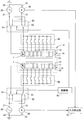
- the input state detection device includes a plurality of capacitive sensor units 10, 10, a plurality of constant voltage power supply devices 20, 20, a plurality of ammeters 30, 30, Electrode side switching units 40 and 40, a plurality of state switching units 50 and 50, a common control unit 60, and a common input detection unit 70 are provided.
- the detection range 5 is a range including a plurality of capacitance type sensor units 10 and 10. Therefore, the input state detection device can detect the non-contact state, the contact non-pressing state, and the pressing state of the human finger 2 against the skin layer 15 over a wide range.
- the input state detection device detects the non-contact state, the contact non-pressing state, and the pressing state by detecting the current flowing through the detection terminal 31 using the ammeter 30.
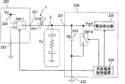
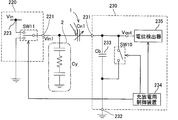
- the input state detection device can detect the input state by detecting the potential at the detection terminal 231 using the following detector 230.
- the input state detection device includes a capacitive sensor unit 10, a constant voltage power supply device 220, a detector 230, an electrode side switching unit 40, a state switching unit 50, a control unit 160, and an input detection unit 170.
- the configuration other than the constant voltage power supply device 220 and the detector 230 in the present embodiment is the same as the configuration given the same reference numerals in the first embodiment or the second embodiment.
- the constant voltage power supply device 220 includes a constant voltage power supply 223 and an input switching element SW11.
- the constant voltage power source 223 is a power source to which an input voltage Vin that is a constant voltage can be applied.
- An application terminal 221 which is one end side of the input switching element SW11 is connected to the capacitive sensor 1 side.
- the other end side of the input switching element SW11 is switchably connected to one of a constant voltage power source 223 and a ground terminal 222 on the ground potential side. That is, when the input switching element SW11 is connected to the constant voltage power source 223 side, the input voltage Vin is applied to the capacitive sensor 1. On the other hand, when the input switching element SW11 is connected to the ground potential side, the input voltage Vin is not applied to the capacitive sensor 1.
- the detector 230 includes a bridge capacitor 233, a charging / discharging switching element SW10, a charging / discharging control device 234, and a potential detector 235.
- the bridge capacitor 233 is connected in series to the other side of the capacitive sensor 1 (a side different from the constant voltage power supply device 220), and is connected between the capacitive sensor 1 and the ground potential. That is, the capacitive sensor 1 and the bridge capacitor 233 form a bridge circuit.
- the capacitance of the bridge capacitor 233 is Cb.
- the charging / discharging switching element SW10 is connected in series to the other of the capacitive sensor 1 and is connected in parallel to the bridge capacitor 233. Further, the charging / discharging switching element SW10 discharges the other charge of the capacitive sensor 1 to the ground potential in the closed state.
- the charging / discharging control device 234 alternately executes the following discharging process and charging process. That is, the charging / discharging control device 234 keeps the input switching element SW11 connected to the ground potential side and closes the charging / discharging switching element SW10, so that the charge of the capacitive sensor 1 is increased. Discharge to ground potential (discharge process).
- the state in which the input switching element SW11 is connected to the ground potential side corresponds to a state in which the input voltage Vin is not applied to the capacitive sensor 1.
- Calibration can be performed by setting the electric charge of the capacitive sensor 1 to the ground potential as a reference state by the discharging step.
- the charging / discharging control device 234 is configured so that, after the discharging step, the input switching element SW11 is connected to the constant voltage power source 223 side and the charging / discharging switching element SW10 is opened.
- the capacitive sensor 1 is charged (charging process).
- the state in which the input switching element SW11 is connected to the constant voltage power source 223 side corresponds to a state in which the input voltage Vin is applied to the capacitive sensor 1.
- the potential detector 235 detects a potential Vout (hereinafter also referred to as “output potential”) between the capacitive sensor 1 and the bridge capacitor 233 when the charging / discharging control device 234 executes the charging process. To do.
- the output potential Vout corresponds to the other potential of the capacitive sensor 1.
- the capacitance Cb and the input voltage Vin of the bridge capacitor 233 are known. Therefore, according to the equation (2), the output potential Vout0 detected by the potential detector 235 becomes a value corresponding to the capacitance of the capacitance type sensor 1.
- the charging / discharging control device 234 performs opening / closing timing of the charging / discharging switching element SW 10, and one of the capacitance type sensors 1.
- the relationship between the potential Vin1 and the output potential Vout will be described with reference to FIG. From T11 to T12, the charging / discharging switching element SW10 is turned on (closed state). Further, the input switching element SW11 is connected to the ground potential side. Accordingly, one potential Vin1 of the capacitive sensor 1 becomes the ground potential.
- the electric charge of the capacitive sensor 1 is discharged through the charging / discharging switching element SW10.
- the output potential Vout between the capacitive sensor 1 and the bridge capacitor 233 becomes the ground potential as the reference state. That is, the output potential Vout is indefinite before the operation, but the output potential Vout is set to the ground potential by the operation.
- the charging / discharging switching element SW10 is turned off (opened), and the input switching element SW11 is connected to the constant voltage power source 223 side. Therefore, one potential Vin1 of the capacitive sensor 1 becomes the input voltage Vin.
- the electrostatic charge sensor 1 is charged.
- the potential detector 235 detects the output potential Vout. The output potential Vout detected by the potential detector 235 is the output potential Vout0 to be detected.
- T14 to T15 the charging / discharging switching element SW10 is turned on (closed), and the input switching element SW11 is connected to the ground potential side.
- one potential Vin1 of the capacitive sensor 1 becomes a ground potential, and the charge of the capacitive sensor 1 is discharged. That is, the output potential Vout becomes the ground potential.
- T15 to T19 the same operation as that of T11 to T15 described above is repeated.
- the bridge capacitor 233 is connected in series to the capacitive sensor 1, and the potential detector 235 is connected to the other potential of the capacitive sensor 1, that is, the capacitive sensor 1 and the bridge.
- the output potential Vout with the capacitor 233 is detected.
- the intermediate potential of the mere two capacitors is indefinite, the capacitance detected using the intermediate potential is not highly accurate.
- the charge of the capacitive sensor 1 is discharged by closing the charging / discharging switching element SW10. That is, the output potential Vout as the intermediate potential becomes the ground potential as the reference state. That is, the output potential Vout is calibrated by closing the charging / discharging switching element SW10.
- the potential detector 235 opens the charge / discharge switching element SW10 after being discharged, and when the input voltage Vin is applied to one of the capacitive sensors 1, the electrostatic capacitance is detected. The other potential of the mold sensor 1 is detected. That is, the potential detected by the potential detector 235 is a potential corresponding to the capacitance Cn0 of the capacitance type sensor 1.
- an equivalent circuit of the input state detection device when the human finger 2 is in a non-contacting state against the skin layer 15 is a circuit as shown in FIG.
- the capacitance of the human finger 2 is assumed to be Cy.
- the output potential Vout1 is the capacitance Cn0 of the capacitance type sensor 1, the capacitance Cb of the bridge capacitor 233, the input voltage Vin, human This is expressed as the following equation (3) by the capacitance Cy of the finger 2.
- the capacitance Cn0 of the capacitance type sensor 1 is substantially a constant value.
- the output potential Vout1 in the non-contact state is smaller than the output potential Vout0 in the non-contact state due to the influence of the electrostatic capacity Cy of the human finger 2. That is, the output potentials Vout0 and Vout1 have the same behavior as the detection value by the ammeter 30 as shown in the first to third embodiments.
- the equivalent circuit of the input state detection device when the human finger 2 is pressed against the skin layer 15 is a circuit as shown in FIG.
- the output potential Vout2 is the electrostatic capacitance Cn1 of the electrostatic capacitance sensor 1, the electrostatic capacitance Cb of the bridge capacitor 233, the input voltage Vin, human This is expressed as the equation (4) by the capacitance Cy of the finger 2.
- the capacitance Cn1 of the capacitive sensor 1 changes according to the pressing force.
- the capacitance Cn1 in the pressed state is larger than the capacitance Cn0 in the non-pressed state. Therefore, when the formula (4) is compared with the formula (3), the output potential Vout2 in the pressed state becomes larger than the output potential Vout1 in the non-pressed state due to the change in the capacitance Cn1 of the capacitive sensor 1. . That is, the output potentials Vout1 and Vout2 have the same behavior as the detection value by the ammeter 30 as shown in the first to third embodiments. As described above, even when the ammeter 30 is replaced with the detector 230, the input state by the human finger 2 is reliably detected.
- the input state detection device always performs detection of the first state or detection of the second state. That is, the input state detection device continuously performs detection in either the first state or the second state.
- the input state detection device may intermittently perform detection in either the first state or the second state at a predetermined cycle. By doing in this way, the frequency
- the capacitance type sensor unit 10 includes the first electrode 11 and the plurality of second electrodes 12a to 12h, thereby constituting eight capacitance type sensors 1. Accordingly, the input detection unit 70 determines where the human finger 2 that is the object is located in the plurality of capacitance-type sensors 1, and further applies contact or pressing force to the skin layer 15. Detect whether or not In addition, the capacitance type sensor unit 10 may constitute one capacitance type sensor 1. In this case, the capacitive sensor unit 10 includes one first electrode and one second electrode. At this time, the electrode side switching part 40 becomes unnecessary.
- Capacitance sensor 1: Capacitance sensor, 2: Human finger (object), 3, 4: Resistance, 10: Capacitance sensor unit, 11: First electrode, 12a-12h: Second electrode, 13: Dielectric Layer, 14: base material, 15: skin layer, 20, 220: constant voltage power supply, 21, 221: application terminal, 22, 222: ground terminal, 30: ammeter (detector), 31, 231: detection terminal 32: 232: ground terminal, 40: electrode side switching unit, 50: state switching unit, 51: first switch, 52: second switch, 60, 160, 260: control unit, 70, 170, 270: input detection Part, 223: constant voltage power supply, 230: detector, 233: capacitor for bridge, 234: controller for charging / discharging, 235: potential detector, SW10: switching element for charging / discharging, SW11: Input switching element, Th1: first threshold value, Th2: the second threshold value, Vin: Input voltage, Vout, Vout1, Vout2, Vout3: output potential
Landscapes
- Engineering & Computer Science (AREA)
- Theoretical Computer Science (AREA)
- General Engineering & Computer Science (AREA)
- Physics & Mathematics (AREA)
- General Physics & Mathematics (AREA)
- Human Computer Interaction (AREA)
- Force Measurement Appropriate To Specific Purposes (AREA)
- Push-Button Switches (AREA)
Abstract
Description
好ましくは、前記定電圧電源装置により印加される前記所定電圧は、周期的な電圧であり、前記検出器は、前記静電容量型センサの静電容量および前記対象物の静電容量に応じた値として、前記検出端子から流れる電流を検出する電流計である。電流計により検出される電流は、静電容量型センサの静電容量および対象物の静電容量に応じた値となる。従って、電流計により検出される電流を用いて、対象物の非接触状態、接触非押付状態および押付状態の判定が可能となる。
入力検出部は、各モードにおいて第一閾値または第二閾値を用いることで、対象物の状態の変化を確実に判定できる。従って、制御部は、各モードの切り替えを適切に行うことができる。
(1.入力状態検出装置の概要)
本実施形態の入力状態検出装置は、静電容量型センサユニット10を備え、導電性の対象物が当該センサユニット10に接触したこと、および、当該センサユニット10を押し付けたことを検出する。例えば、導電性の対象物は、人間の指として、人間の指が当該センサユニット10に接触したこと、および、人間の指によって当該センサユニット10を押し付けたことを検出する。さらに、人間の指によって当該センサユニット10を押し付けた状態において、入力状態検出装置は、押付力を検出することもできる。
入力状態検出装置は、上述したように、静電容量型センサユニット10を備える。まず、静電容量型センサユニット10について、図1および図2を参照して説明する。静電容量型センサユニット10は、後述する複数個の静電容量型センサ1を構成する。ただし、静電容量型センサユニット10は、1個の静電容量型センサ1を構成するようにしてもよい。
次に、入力状態検出装置において、静電容量型センサユニット10以外の構成について図1を参照して説明する。入力状態検出装置は、図1に示すように、静電容量型センサユニット10の他に、定電圧電源装置20、電流計30、電極側切替部40、状態切替部50、制御部60、入力検出部70を備える。
次に、上述した入力状態検出装置の等価回路について、図3を参照して説明する。図3は、静電容量型センサユニット10の任意の静電容量型センサ1を計測対象とした場合の等価回路を示す。
次に、第一状態において、対象物である人間の指2が表皮層15に接触した場合を考える。このときの回路は、図4に示すようになる。つまり、第一電極11側に定電圧電源装置20により周期的な電圧が印加される。一方、第二電極12a~12hが、抵抗4を介して電流計30の検出端子31に接続される。そして、人間の指2は、第二電極12a~12hと電流計30の検出端子31との間に接続される。つまり、人間の指2の等価回路が、静電容量型センサ1に直列接続され、且つ、電流計30および抵抗4の直列回路に対して並列接続される。
次に、第二状態において、対象物である人間の指2が表皮層15に対して押付力を付与した場合を考える。このときの回路は、図5に示すようになる。つまり、第二電極12a~12h側に定電圧電源装置20により周期的な定電圧が印加される。一方、第一電極11が、抵抗3を介して電流計30の検出端子31に接続される。そして、人間の指2は、静電容量型センサ1と定電圧電源装置20の印加端子21との間に接続される。つまり、人間の指2の等価回路が、静電容量型センサ1、電流計30および抵抗3の直列回路に対して並列接続される。
次に、制御部60により状態切替部50の第一,第二スイッチ51,52の切替タイミングについて、図6を参照して説明する。
第二実施形態の入力状態検出装置について、図7および図8を参照して説明する。本実施形態の入力状態検出装置は、第一実施形態の入力状態検出装置に対して、制御部160および入力検出部170が相違する。他の構成は、同一符号を付して、説明を省略する。

第三実施形態の入力状態検出装置における制御部160の動作について、図9を参照して説明する。本実施形態の入力状態検出装置は、第二実施形態の入力状態検出装置と実質的に同様の構成となる。
第一~第三実施形態においては、複数の静電容量型センサ1が一列に並んで構成される。図10に示すように、入力状態検出装置は、複数の静電容量型センサユニット10,10と、それぞれに対応する複数の定電圧電源装置20,20、複数の電流計30,30、複数の電極側切替部40,40、複数の状態切替部50,50と、共通の制御部60、共通の入力検出部70を備える。
上記実施形態においては、入力状態検出装置は、電流計30を用いて検出端子31に流れる電流を検出することで、非接触状態、接触非押付状態および押付状態を検出した。この他に、入力状態検出装置は、以下の検出器230を用いて、検出端子231における電位を検出することで、入力状態を検出することができる。
検出器230を用いる入力状態検出装置について、図11を参照して説明する。入力状態検出装置は、静電容量型センサユニット10、定電圧電源装置220、検出器230、電極側切替部40、状態切替部50、制御部160、入力検出部170を備える。ここで、本実施形態における定電圧電源装置220および検出器230以外の構成は、第一実施形態または第二実施形態において同一符号を付す構成と同様である。
人間の指2が表皮層15に対して非接触状態のときの入力状態検出装置の等価回路は、図12に示すような回路となる。入力用スイッチング素子SW11が定電圧電源223側に接続される状態において、出力電位Vout0は、静電容量型センサ1の静電容量Cn0、ブリッジ用キャパシタ233の静電容量Cb、入力電圧Vinによって、式(2)のように表される。

次に、人間の指2が表皮層15に対して非接触状態のときにおいて、充放電用制御装置234が実行する充放電用スイッチング素子SW10の開閉のタイミングと、静電容量型センサ1の一方の電位Vin1および出力電位Voutの関係について、図13を参照して説明する。T11~T12において、充放電用スイッチング素子SW10がON(閉状態)とされる。また、入力用スイッチング素子SW11がグランド電位側に接続される。従って、静電容量型センサ1の一方の電位Vin1が、グランド電位となる。
第一状態において、人間の指2が表皮層15に対して接触非押付状態のときの入力状態検出装置の等価回路は、図14に示すような回路となる。ここで、便宜上、人間の指2の静電容量をCyとする。入力用スイッチング素子SW11が定電圧電源223側に接続される状態において、出力電位Vout1は、静電容量型センサ1の静電容量Cn0、ブリッジ用キャパシタ233の静電容量Cb、入力電圧Vin、人間の指2の静電容量Cyによって、式(3)のように表される。ここで、接触非押付状態においては、静電容量型センサ1の静電容量Cn0は、実質上、一定値である。


上記において、入力状態検出装置は、常に、第一状態による検出と第二状態の検出の何れかを行うこととした。つまり、入力状態検出装置は、第一状態と第二状態の何れかによる検出を連続的に行った。この他に、入力状態検出装置は、第一状態と第二状態の何れかによる検出を所定の周期で断続的に行ってもよい。このようにすることで、状態切替部50による切替動作の回数がさらに少なくなり、より消費エネルギーが低減する。
Claims (12)
- 基材に取り付けられる第一電極と、接触する導電性の対象物側に位置する第二電極と、前記第一電極と前記第二電極との間に配置されると共に前記対象物による前記第二電極への押付力によって圧縮される誘電層とを備える静電容量型センサと、
印加端子を前記静電容量型センサ側に接続し、前記静電容量型センサに対して所定電圧を印加する定電圧電源装置と、
前記静電容量型センサに直列接続され、検出端子を前記静電容量型センサ側に接続し、前記静電容量型センサの静電容量および前記対象物の静電容量に応じて変化する前記検出端子における電位または前記検出端子から流れる電流を検出する検出器と、
前記定電圧電源装置の印加端子を前記第一電極側に接続し、かつ、前記検出器の検出端子を前記第二電極側に接続する第一状態と、前記定電圧電源装置の印加端子を前記第二電極側に接続し、かつ、前記検出器の検出端子を前記第一電極側に接続する第二状態とを切替可能な状態切替部と、
前記第一状態における前記検出器の検出値に基づいて前記対象物が前記静電容量型センサにおける前記第二電極側の面に対して非接触状態であるか接触非押付状態であるかを検出すると共に、前記第二状態における前記検出器の検出値に基づいて前記対象物が前記第二電極に対して接触非押付状態であるか押付状態であるかを検出する入力検出部と、
を備える、入力状態検出装置。 - 前記定電圧電源装置により印加される前記所定電圧は、周期的な電圧であり、
前記検出器は、前記静電容量型センサの静電容量および前記対象物の静電容量に応じた値として、前記検出端子から流れる電流を検出する電流計である、請求項1に記載の入力状態検出装置。 - 前記検出器は、
前記検出器の前記検出端子とグランド電位との間に接続されるブリッジ用キャパシタと、
前記ブリッジ用キャパシタに対して並列接続され、閉状態時に前記検出端子の電荷をグランド電位に放電する充放電用スイッチング素子と、
前記定電圧電源装置が前記静電容量型センサに対して前記所定電圧を印加していない状態において、前記検出端子の電荷をグランド電位に放電する工程と、前記放電する工程の後に、前記充放電用スイッチング素子を開状態にし且つ前記定電圧電源装置により前記所定電圧が印加される状態にすることで、前記静電容量型センサに充電する工程とを実行する充放電用制御装置と、
前記充放電用制御装置による前記充電する工程において、前記静電容量型センサの静電容量および前記対象物の静電容量に応じた値として、前記検出端子の電位を検出する電位検出器と、
を備える、請求項1に記載の入力状態検出装置。 - 前記入力検出部は、前記第二状態における前記検出器の検出値に基づいて、前記対象物が前記第二電極へ付与した押付力の大きさを検出する、請求項1~3の何れか一項に記載の入力状態検出装置。
- 前記入力状態検出装置は、前記状態切替部の状態を制御する制御部を備え、
前記制御部は、前記状態切替部を前記第一状態と前記第二状態とに周期的に切り替え、
前記入力検出部は、前記非接触状態であるか前記接触非押付状態であるかの検出と、前記接触非押付状態であるか前記押付状態であるかの検出とを周期的に行う、請求項1~4の何れか一項に記載の入力状態検出装置。 - 前記状態切替部に前記第一状態を継続させるモードは第一モードとし、前記状態切替部に前記第二状態を継続させるモードは第二モードとし、前記状態切替部に前記第一状態と前記第二状態とを周期的に交互に切り替えさせるモードは第三モードとし、
前記入力状態検出装置は、前記状態切替部のモードを制御する制御部を備え、
前記制御部は、
前記非接触状態から前記接触非押付状態に変化するときに、前記状態切替部を前記第一モードから前記第三モードに切り替え、
前記接触非押付状態から前記非接触状態に変化するときに、前記状態切替部を前記第三モードから前記第一モードに切り替え、
前記接触非押付状態から前記押付状態に変化するときに、前記状態切替部を前記第三モードから前記第二モードに切り替え、
前記押付状態から前記接触非押付状態に変化するときに、前記状態切替部を前記第二モードから前記第三モードに切り替える、
請求項1~4の何れか一項に記載の入力状態検出装置。 - 前記入力検出部は、
前記第一モードのときに前記第一状態における前記検出器の検出値が第一閾値を下回ることで前記非接触状態から前記接触非押付状態に変化すると判定し、
前記第三モードのときに前記第一状態における前記検出器の検出値が前記第一閾値を上回ることで前記接触非押付状態から前記非接触状態に変化すると判定し、
前記第三モードのときに前記第二状態における前記検出器の検出値が第二閾値を上回ることで前記接触非押付状態から前記押付状態に変化すると判定し、
前記第二モードのときに前記第二状態における前記検出器の検出値が前記第二閾値を下回ることで前記押付状態から前記接触非押付状態に変化すると判定し、
前記制御部は、前記入力検出部による判定に基づいて、前記非接触状態、前記接触非押付状態および前記押付状態の変化を取得する、
請求項6に記載の入力状態検出装置。 - 前記接触非押付状態のときの前記第一状態における前記検出器の検出値と前記第一閾値との差が、前記接触非押付状態のときの前記第二状態における前記検出器の検出値と前記第二閾値との差より大きくなるように、
前記第一閾値および前記第二閾値が設定される、
請求項7に記載の入力状態検出装置。 - 前記状態切替部に前記第一状態を継続させるモードは第一モードとし、前記状態切替部に前記第二状態を継続させるモードは第二モードとし、
前記入力状態検出装置は、前記状態切替部の状態を制御する制御部を備え、
前記制御部は、
前記非接触状態から前記接触非押付状態に変化するときに、前記状態切替部を前記第一モードから前記第二モードに切り替え、
前記押付状態から前記接触非押付状態に変化するときに、前記状態切替部を前記第二モードから前記第一モードに切り替える、
請求項1~4の何れか一項に記載の入力状態検出装置。 - 前記第一電極および前記第二電極の少なくとも何れか一方を複数備えることにより、複数個の静電容量型センサを構成し、
前記入力検出部は、前記対象物が存在する位置を検出する、請求項1~9の何れか一項に記載の入力状態検出装置。 - 前記誘電層はエラストマーまたは樹脂で形成される、請求項1~10の何れか一項に記載の入力状態検出装置。
- 前記第一電極および前記第二電極は、エラストマーに導電性フィラーを配合させることによって形成される、請求項1~11の何れか一項に記載の入力状態検出装置。
Priority Applications (4)
| Application Number | Priority Date | Filing Date | Title |
|---|---|---|---|
| EP14831907.2A EP2950190B1 (en) | 2013-07-30 | 2014-06-30 | Input state detection device |
| JP2015529468A JP6286430B2 (ja) | 2013-07-30 | 2014-06-30 | 入力状態検出装置 |
| CN201480043281.7A CN105453008B (zh) | 2013-07-30 | 2014-06-30 | 输入状态检测装置 |
| US14/810,716 US10133413B2 (en) | 2013-07-30 | 2015-07-28 | Input state detection device |
Applications Claiming Priority (2)
| Application Number | Priority Date | Filing Date | Title |
|---|---|---|---|
| JP2013-157806 | 2013-07-30 | ||
| JP2013157806 | 2013-07-30 |
Related Child Applications (1)
| Application Number | Title | Priority Date | Filing Date |
|---|---|---|---|
| US14/810,716 Continuation US10133413B2 (en) | 2013-07-30 | 2015-07-28 | Input state detection device |
Publications (1)
| Publication Number | Publication Date |
|---|---|
| WO2015015983A1 true WO2015015983A1 (ja) | 2015-02-05 |
Family
ID=52431524
Family Applications (1)
| Application Number | Title | Priority Date | Filing Date |
|---|---|---|---|
| PCT/JP2014/067440 Ceased WO2015015983A1 (ja) | 2013-07-30 | 2014-06-30 | 入力状態検出装置 |
Country Status (5)
| Country | Link |
|---|---|
| US (1) | US10133413B2 (ja) |
| EP (1) | EP2950190B1 (ja) |
| JP (1) | JP6286430B2 (ja) |
| CN (1) | CN105453008B (ja) |
| WO (1) | WO2015015983A1 (ja) |
Cited By (3)
| Publication number | Priority date | Publication date | Assignee | Title |
|---|---|---|---|---|
| WO2018179471A1 (ja) * | 2017-03-27 | 2018-10-04 | Smk株式会社 | 感圧式静電スイッチおよび電気装置 |
| JP2019149207A (ja) * | 2015-03-02 | 2019-09-05 | 学校法人福岡大学 | 近接・接触センサ |
| JP2019153558A (ja) * | 2018-03-06 | 2019-09-12 | 株式会社デンソー | 静電容量式操作装置 |
Families Citing this family (18)
| Publication number | Priority date | Publication date | Assignee | Title |
|---|---|---|---|---|
| US9660646B1 (en) * | 2013-03-10 | 2017-05-23 | Apple Inc. | Multiple controllers for a capacitive sensing device |
| DE112015005942B4 (de) * | 2015-01-13 | 2026-04-02 | Sumitomo Riko Company Limited | Kapazitätsmessvorrichtung, kapazitätstypartige Flachsensoreinrichtung und kapazitätstypartige Flüssigkeitspegeldetektionseinrichtung |
| SE1650548A1 (en) * | 2016-04-22 | 2017-10-23 | Fingerprint Cards Ab | Fingerprint sensing system with sensing reference potential providing circuitry |
| IT201600103234A1 (it) | 2016-10-14 | 2018-04-14 | Green Seas Ventures Ldt | Sistema Costruttivo afferente un sensore capacitivo di tensione |
| CN108334222A (zh) * | 2017-01-19 | 2018-07-27 | 希迪普公司 | 触摸输入装置 |
| DE102017106207A1 (de) * | 2017-03-22 | 2018-09-27 | Fm Marketing Gmbh | Rasterplatte |
| IT201800004114A1 (it) | 2018-03-30 | 2019-09-30 | Green Seas Ventures Ltd C/O Citco B V I Ltd | Sistema costruttivo afferente un sensore capacitivo di tensione |
| DE102018205084A1 (de) * | 2018-04-04 | 2019-10-10 | Audi Ag | Kapazitives Sensorbauteil |
| CN119986166A (zh) | 2018-12-17 | 2025-05-13 | G&W电气公司 | 电传感器组合件 |
| US11340266B2 (en) | 2018-12-17 | 2022-05-24 | G & W Electric Company | Electrical sensor assembly |
| JP7216963B2 (ja) * | 2019-10-03 | 2023-02-02 | 本田技研工業株式会社 | 静電容量型検知センサ、静電容量型検知センサモジュールおよび静電容量型検知センサを用いた状態判定方法 |
| TWI744760B (zh) * | 2019-12-30 | 2021-11-01 | 財團法人工業技術研究院 | 靜電感測系統與靜電感測組件 |
| TWI768439B (zh) * | 2020-08-20 | 2022-06-21 | 黃湘豪 | 非入侵式通訊檢查和控制裝置 |
| JP7595321B2 (ja) * | 2021-01-14 | 2024-12-06 | 本田技研工業株式会社 | 計測装置 |
| JP7542448B2 (ja) * | 2021-01-14 | 2024-08-30 | 株式会社ジャパンディスプレイ | 圧力センサ |
| US11755095B2 (en) | 2021-07-19 | 2023-09-12 | Stmicroelectronics S.R.L. | Bag detection using an electrostatic charge sensor |
| JP7471368B2 (ja) * | 2022-09-30 | 2024-04-19 | 住友理工株式会社 | 接触検知装置 |
| CN116899770A (zh) * | 2023-07-12 | 2023-10-20 | 珠海格力电器股份有限公司 | 花洒及其控制方法、装置、存储介质以及电子设备 |
Citations (2)
| Publication number | Priority date | Publication date | Assignee | Title |
|---|---|---|---|---|
| JPH0764725A (ja) * | 1993-08-26 | 1995-03-10 | Philips Electron Nv | タッチスクリーン及び力センサを有するデータ処理装置 |
| JP2010217967A (ja) | 2009-03-13 | 2010-09-30 | Alps Electric Co Ltd | 入力装置 |
Family Cites Families (11)
| Publication number | Priority date | Publication date | Assignee | Title |
|---|---|---|---|---|
| JP3001395B2 (ja) * | 1995-04-04 | 2000-01-24 | 株式会社ワコム | 位置検出装置及び位置検出方法 |
| JP3394187B2 (ja) * | 1997-08-08 | 2003-04-07 | シャープ株式会社 | 座標入力装置および表示一体型座標入力装置 |
| CN104965621B (zh) * | 2006-06-09 | 2018-06-12 | 苹果公司 | 触摸屏液晶显示器及其操作方法 |
| CN101490642A (zh) * | 2006-07-18 | 2009-07-22 | Iee国际电子工程股份公司 | 输入设备 |
| US8063886B2 (en) * | 2006-07-18 | 2011-11-22 | Iee International Electronics & Engineering S.A. | Data input device |
| KR101578075B1 (ko) * | 2009-04-20 | 2015-12-17 | 삼성디스플레이 주식회사 | 터치 검출 방법 및 이를 수행하기 위한 터치 검출 장치 |
| JP5396335B2 (ja) * | 2009-05-28 | 2014-01-22 | 株式会社半導体エネルギー研究所 | タッチパネル |
| JP2012022635A (ja) * | 2010-07-16 | 2012-02-02 | Alps Electric Co Ltd | 静電容量式近接センサ装置、及びそれを用いた静電容量式モーション検出装置 |
| EP2690786A1 (en) * | 2012-07-25 | 2014-01-29 | Electrolux Home Products Corporation N.V. | A control device, in particular for a domestic appliance |
| JP6248406B2 (ja) * | 2013-04-09 | 2017-12-20 | 日本電産リード株式会社 | 検査装置及び検査方法 |
| US9279841B2 (en) * | 2013-07-29 | 2016-03-08 | Tritan Technology Inc. | Integratable capacitive touch sensing circuit through charge sharing |
-
2014
- 2014-06-30 JP JP2015529468A patent/JP6286430B2/ja active Active
- 2014-06-30 EP EP14831907.2A patent/EP2950190B1/en active Active
- 2014-06-30 CN CN201480043281.7A patent/CN105453008B/zh active Active
- 2014-06-30 WO PCT/JP2014/067440 patent/WO2015015983A1/ja not_active Ceased
-
2015
- 2015-07-28 US US14/810,716 patent/US10133413B2/en active Active
Patent Citations (2)
| Publication number | Priority date | Publication date | Assignee | Title |
|---|---|---|---|---|
| JPH0764725A (ja) * | 1993-08-26 | 1995-03-10 | Philips Electron Nv | タッチスクリーン及び力センサを有するデータ処理装置 |
| JP2010217967A (ja) | 2009-03-13 | 2010-09-30 | Alps Electric Co Ltd | 入力装置 |
Cited By (4)
| Publication number | Priority date | Publication date | Assignee | Title |
|---|---|---|---|---|
| JP2019149207A (ja) * | 2015-03-02 | 2019-09-05 | 学校法人福岡大学 | 近接・接触センサ |
| WO2018179471A1 (ja) * | 2017-03-27 | 2018-10-04 | Smk株式会社 | 感圧式静電スイッチおよび電気装置 |
| JP2019153558A (ja) * | 2018-03-06 | 2019-09-12 | 株式会社デンソー | 静電容量式操作装置 |
| JP6996355B2 (ja) | 2018-03-06 | 2022-01-17 | 株式会社デンソー | 静電容量式操作装置 |
Also Published As
| Publication number | Publication date |
|---|---|
| JPWO2015015983A1 (ja) | 2017-03-02 |
| US10133413B2 (en) | 2018-11-20 |
| EP2950190B1 (en) | 2019-05-22 |
| US20150346907A1 (en) | 2015-12-03 |
| CN105453008A (zh) | 2016-03-30 |
| CN105453008B (zh) | 2018-09-07 |
| EP2950190A4 (en) | 2016-08-24 |
| EP2950190A1 (en) | 2015-12-02 |
| JP6286430B2 (ja) | 2018-02-28 |
Similar Documents
| Publication | Publication Date | Title |
|---|---|---|
| JP6286430B2 (ja) | 入力状態検出装置 | |
| JP5326042B2 (ja) | 静電容量型センサ装置および静電容量型センサの静電容量計測装置 | |
| KR101742604B1 (ko) | 용량성 전압 분배기 터치 센서 | |
| CN102893241B (zh) | 检测触摸输入并生成可感知的触摸刺激 | |
| CN109154872B (zh) | 用于检测和表征表面上的力输入的系统和方法 | |
| CN106461713B (zh) | 静电电容测量装置、静电电容型面状传感器装置以及静电电容型液位检测装置 | |
| JP7127040B2 (ja) | 感圧スタイラス | |
| US20170010130A1 (en) | Pliable capacitive structure apparatus and methods | |
| KR101573521B1 (ko) | 필압의 감지가 가능한 터치 펜 | |
| US20170228086A1 (en) | Sensing device for force and tactile-proximity sensing | |
| JP6183042B2 (ja) | タッチセンサ | |
| US10551982B2 (en) | Instruction reception apparatus, information processing apparatus, signal processing method, and program | |
| KR102066329B1 (ko) | 촉각 센서, 그 제조 방법 및 그 동작 방법 | |
| KR20150096318A (ko) | 압력 센서 및 스타일러스 펜 | |
| JP5666711B2 (ja) | タッチ認識方法と、タッチキー構造と、タッチデバイス | |
| CN101738542A (zh) | 抗干扰的电容检测装置及方法 | |
| JP6182031B2 (ja) | 静電容量計測装置、静電容量型面状センサ装置および静電容量型液位検出装置 | |
| WO2006133594A8 (en) | Circuit and process for power management | |
| KR101578036B1 (ko) | 용량성 터치입력장치를 이용한 압력감지방법 | |
| Hsu et al. | In-skin pressure and curvature sensors for soft robots | |
| JP5721745B2 (ja) | 多数の容量性センサ素子の静電容量を決定するための回路装置 | |
| US20250216992A1 (en) | Input Device | |
| KR20210032026A (ko) | 사용자 의도 센싱 장치 | |
| EP2722985B1 (en) | Method of differential measurement of voltage levels of capacitive change. | |
| KR20250096171A (ko) | 포스와 터치의 통합 센서 |
Legal Events
| Date | Code | Title | Description |
|---|---|---|---|
| WWE | Wipo information: entry into national phase |
Ref document number: 201480043281.7 Country of ref document: CN |
|
| 121 | Ep: the epo has been informed by wipo that ep was designated in this application |
Ref document number: 14831907 Country of ref document: EP Kind code of ref document: A1 |
|
| WWE | Wipo information: entry into national phase |
Ref document number: 2014831907 Country of ref document: EP |
|
| ENP | Entry into the national phase |
Ref document number: 2015529468 Country of ref document: JP Kind code of ref document: A |
|
| NENP | Non-entry into the national phase |
Ref country code: DE |