WO2015016012A1 - イヤリングとそのための装着具 - Google Patents
イヤリングとそのための装着具 Download PDFInfo
- Publication number
- WO2015016012A1 WO2015016012A1 PCT/JP2014/068142 JP2014068142W WO2015016012A1 WO 2015016012 A1 WO2015016012 A1 WO 2015016012A1 JP 2014068142 W JP2014068142 W JP 2014068142W WO 2015016012 A1 WO2015016012 A1 WO 2015016012A1
- Authority
- WO
- WIPO (PCT)
- Prior art keywords
- lever
- rear end
- earring
- end portion
- tool according
- Prior art date
- Legal status (The legal status is an assumption and is not a legal conclusion. Google has not performed a legal analysis and makes no representation as to the accuracy of the status listed.)
- Ceased
Links
Images





Classifications
-
- A—HUMAN NECESSITIES
- A44—HABERDASHERY; JEWELLERY
- A44C—PERSONAL ADORNMENTS, e.g. JEWELLERY; COINS
- A44C7/00—Ear-rings; Devices for piercing the ear-lobes
- A44C7/004—Ear-clips
- A44C7/006—Ear-clips with a pivotable back clamping arm
-
- A—HUMAN NECESSITIES
- A44—HABERDASHERY; JEWELLERY
- A44C—PERSONAL ADORNMENTS, e.g. JEWELLERY; COINS
- A44C7/00—Ear-rings; Devices for piercing the ear-lobes
- A44C7/004—Ear-clips
- A44C7/005—Ear-clips made of one piece
-
- B—PERFORMING OPERATIONS; TRANSPORTING
- B25—HAND TOOLS; PORTABLE POWER-DRIVEN TOOLS; MANIPULATORS
- B25B—TOOLS OR BENCH DEVICES NOT OTHERWISE PROVIDED FOR, FOR FASTENING, CONNECTING, DISENGAGING, OR HOLDING
- B25B7/00—Pliers; Other hand-held gripping tools with jaws on pivoted limbs; Details applicable generally to pivoted-limb hand tools
- B25B7/06—Joints
- B25B7/08—Joints with fixed fulcrum
Definitions
- This invention relates to an earring such as a piercing and a mounting tool therefor.
- an earring (Patent Document 1) in which a small loop is formed by winding an elastic wire around a concave portion of an elastic wire formed in a U shape by attaching a decorative body to both ends, and using pure titanium to prevent rusting, U
- a pair of semi-circular ring pieces that are hinged to each other via a washer and crimped to create a force to be sandwiched between the other ends of the ring pieces (Patent Document 2)
- Earrings (Patent Document 3) and the like have been proposed. It also has a pipe bent into a circular shape with a coil spring inside and a pin attached to the end of the coil spring and protruding from one end of the pipe. Earrings (Non-Patent Document 1) designed to be sandwiched are sold.
- the earrings described in Patent Documents 1 and 2 may be inadvertently widened and the wire rod may be plastically deformed if the distance between both ends is increased only by the finger force when attached to the earlobe.
- the earring described in Patent Document 3 is inferior in decorativeness due to the conspicuous hinged portion.
- the earring described in Non-Patent Document 1 is painful when worn for a long time because excessive pressure is applied to the earlobe. It is therefore an object of the present invention to provide a tool for wearing an earring that looks like a piercing and can be fixed to the earlobe by its own elastic restoring force and does not cause pain.
- the earring of the present invention is A connecting portion made of an elastic wire and bent to maintain a predetermined separation between both ends, It is made of the same or different material as the material, and has a pair of ear pads provided at both ends of the connecting part so as to be wider than the connecting part and facing the main surfaces.
- the elastic wire may be a high-strength piano wire or a superelastic wire.
- Superelasticity refers to the property of returning to its original shape when the deformation force is removed even when deformed with a large strain exceeding 0.5%.
- the Young's modulus is generally 40 to 90 GPa, and the elastic deformability It has a property of 2.0 to 7%.
- the predetermined separation depends on the thickness of the earlobe of the person wearing the earrings and is generally 40-80% of the maximum thickness of the earlobe.
- the ear pad while wearing, the ear pad holds the earlobe by the elastic force of the connecting portion, so that it looks like a piercing.
- the gap between both ends of the connecting portion is kept, the gap between both ear pads is also kept, and no excessive pressure is applied to the earlobe.
- the ear pad is wider than the connecting part, the pressure applied to the earlobe from the connecting part is dispersed. For this reason, even if worn for a long time, there is no pain.
- the material of the ear pad portion may be different from that of the connecting portion or may be the same. When they are different, they may be fixed to the connecting part by adhesion or welding via an adhesive. When they are the same, they are provided integrally with the connecting portion.
- the ornament may be attached to one or two of the pair of ear pads, or may be attached to the connecting portion.
- the connecting portion is made of a superelastic material
- the pinching force is unlikely to decrease.
- the material having superelasticity is made of a Ti—Ni shape memory alloy
- the distance between both ends of the connecting portion may be freely adjusted at a temperature lower than the martensite transformation start temperature (Ms point).
- Ms point martensite transformation start temperature
- the material having superelasticity has a body-centered cubic structure and is made of a ⁇ -type titanium alloy called rubber metal (registered trademark)
- the force to pinch the earlobe does not decrease even when worn in a cold region. That's fine.
- the connecting part is preferably U-shaped. It looks like the most piercing and is easy to process.
- the pair of ear pads preferably have buffer portions made of rubber such as silicon rubber or urethane rubber on the inner surfaces facing each other. This is because, when the earring is worn, it softly hits against the earlobe, and even if an unexpected impact is applied to the earring during wearing, it is absorbed to some extent to prevent injury.
- a suitable mounting device comprises a pair of levers. Each of these levers has a front end portion and a rear end portion, and the front end portion opens (closes) when the rear end portion closes (opens), and the lever is interposed between the front end portion and the rear end portion via a rotating shaft. Are connected. That is, the front end portion and the rear end portion open and close in directions opposite to each other.
- the distal end portion is closed or half-opened, the distal end portion is inserted inside or in the vicinity of the pair of ear pad portions, and the rear end portion is closed, thereby weakening the finger force.
- the interval between the ear pads can be easily increased.
- it can also prevent that the space
- the outer surface of the tip is pressed against the inner surface of the ear pad or near both ends of the joint against the elastic restoring force of the connector, so that the earring is held at the tip. Is done. For this reason, the earring is fixed to the earlobe by inserting the earlobe between the front end portions while holding the closed rear end portion and then loosening the gripping force on the rear end portion and pulling out the wearing tool.
- At least one of the levers preferably has a bearing portion that protrudes inward between the front end portion and the rear end portion. With this configuration, the operation of opening and closing the front end portion and the rear end portion in directions opposite to each other can be easily realized.
- the tip of at least one lever of the lever has a shallowly recessed outer surface that approaches the tip of the other lever toward the bottom. With this configuration, when a ball is attached to the ear pad or the buffer portion is provided, the ball or the buffer portion is fitted in the shallow recess, and the earring is less likely to drop from the wearing tool.
- the tip of at least one lever of the lever preferably has a flat outer surface parallel to the rotation axis. This is because this configuration makes it easy to pull out the wearing tool from between the earring and the earlobe.
- the tip of the lever may be inserted directly under the ear pad and pressed against the elastic wire.
- This method makes it easier to pull out the wearing tool from between the earring and the earlobe.
- the tip of at least one lever of the lever preferably has a flat outer surface that forms an acute angle with respect to the rotation axis. With this configuration, when the interval between the ear pads is increased, the entire outer surface of the tip of the lever comes into contact with the elastic wire, so that the interval between the ear pads can be easily increased and the wearing tool can be easily pulled out.
- the tips of both levers have the flat outer surface and / or the shallowly recessed outer surface.
- the pivot angle of the lever is preferably limited by the rear end of the first lever and the rear end of the second lever abutting each other. With this configuration, the maximum distance between the outer surfaces of the distal end portions can be always determined to be constant.
- the tip of at least one lever of the lever is preferably thinner than the rear end of the lever as viewed in the axial direction. With this configuration, even if the interval between the ear pads is narrow, the tip portion can be easily inserted into the same interval. In a particularly preferred configuration, the front ends of both levers are thinner than the rear end.
- the rear end portion of at least one lever of the lever is preferably wider in the axial direction than the front end portion of the lever. This is because the rear end portion is easily held by this configuration. In a particularly preferred configuration, the rear ends of both levers are wide.
- the maximum distance of the outer surface of the tip when the tip is open is usually 10 mm or less, preferably 8 mm or less, particularly preferably 6 mm or less. Although it depends on the total length, elastic modulus and outer diameter of the elastic wire constituting the connecting portion, by setting the maximum interval of the outer surface of the tip portion to 6 mm or less, the interval between the ear pad portions is always expanded within the elastic range of the connecting portion. Thus, plastic deformation of the connecting portion can be reliably prevented.
- the mounting tool preferably includes a spring that biases the rear end portions of the pair of levers to open. Even if no external force is applied, the distal end is closed by the force of the spring, so that the distal end can be easily inserted between the ear pads.
- the earring of the present invention looks like a pierced earring and does not cause a pain without decreasing the pinching force, so that the wearer can easily attach the same decoration to the earring.
- the earring wearing device of the present invention the earring can be easily attached to the earlobe regardless of the force of the finger, and the earring is not plastically deformed.
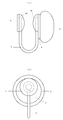
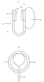
- (A) is a front view which shows the earring of Embodiment 1, (b) is a side view similarly.
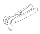
- (A) is a front view which shows the mounting tool of Embodiment 1,
- (b) is a top view similarly,
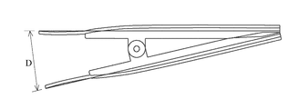
- (c) is DD sectional drawing in (a).
- (A) is a front view which shows the 1st lever of the said mounting tool,
- (b) is a top view similarly,
- (c) is a bottom view which shows a 2nd lever.
- (A) is AA sectional drawing in Fig.3 (a)
- (b) is BB sectional drawing similarly
- (c) is CC sectional drawing similarly.
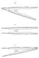
- (a) is the state which the front-end
- (b) is a half-open state
- (c) is a front view which shows the open state. It is a perspective view which shows the method of expanding the space
- FIG. 1 It is a front view which shows the mounting tool of Embodiment 3. It is a top view which shows the mounting tool of Embodiment 4.
- A is a front view which shows the earring of Embodiment 5, (b) is a side view similarly.
- (A) is a front view which shows the intermediate product of the earring of Embodiment 6, (b) is a side view similarly.
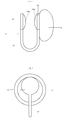
- (A) is a front view which shows the earring of Embodiment 6, (b) is a left side view similarly, (c) is a right side view similarly. It is the figure which looked at the place which attached the earring of Embodiment 1 to the earlobe using the mounting tool of Embodiment 7 from the front of the earring.
- (A) is a front view which shows the earring of Embodiment 8, (b) is a side view similarly.
- the earring 1 of this embodiment includes a U-shaped connecting portion 2 in front view, disk-shaped ear pads 3 and 4 fixed to both ends of the connecting portion, and a decoration 5.
- the connecting portion 2 bends a wire made of a Ti—Ni shape memory alloy having a diameter of 0.7 mm into a U-shape with a distance between both ends equal to or less than the transformation point, for example, 4 mm to 5 mm, and perpendicular to the U-shape. It is further bent so that the vicinity of both ends becomes a ring in a plane parallel to the center line of the U-shape.
- the distance between the both ends of the U-shape and the bottom may be about 10 mm, for example, so that both ends of the U-shape hit the thin portion of the earlobe without pushing up the earlobe.
- the ear pads 3 and 4 are each made of metal such as brass, iron, and stainless steel having a thickness of 0.5 mm, and are bonded or welded to the outer sides of the rings at both ends of the connecting portion 2 via an adhesive. Silicone rubber is applied to the inner surfaces of the ear pads 3 and 4 so that the ring portions at both ends of the connecting portion 2 are buried to constitute the buffer portions 3a and 4a.
- the ear pad 3 has a diameter of 5 mm, and the ear pad 4 has a diameter of 7 mm.
- the ornament 5 is attached to the outer surface of the ear pad 4.
- the interval between the buffer portions 3a and 4a is usually 0.7 to 1.3 mm, although it depends on the thickness of the earlobe of the person wearing the earring 1.
- the earring 1 When wearing the earring 1, put the earring 1 in the refrigerator and cool it, and take out the refrigerator from the refrigerator and adjust the distance between the ear pads 3 and 4 appropriately. This work becomes unnecessary after that, as long as the wearer does not change as long as the distance reaches the wearer's satisfaction.
- the interval between the ear pads 3 and 4 of the earring 1 at room temperature is widened with fingers, the earlobe is inserted between the ear pads 3 and 4, the finger force is removed, and the ear pads are removed with the ear pads 3 and 4.
- the earring 1 is fixed to the ear. Since the buffer portions 3a and 4a softly hit the earlobe, the earring 1 does not damage the earlobe when the earlobe is inserted. Further, even if an unexpected impact is applied to the earring 1 during wearing, the buffer portions 3a and 4a absorb a part of the impact, so that they are rarely injured.
- the ear pads 3 and 4 hold the earlobe by the elastic force of the connecting portion 2, so that it looks like a piercing. And since the connection part 2 consists of shape memory alloys, the pinching force does not fall. In addition, since the gap between both ends of the connecting portion 2 is kept at the thickness of the earlobe, the same gap is kept between the ear pads 3 and 4 so that excessive pressure is not applied to the earlobe. Moreover, since the ear pads 3 and 4 are made of a plate material wider than the diameter of the wire, the pressure applied from the wire to the earlobe is dispersed. For this reason, even if worn for a long time, there is no pain.
- the wearing tool 6 shown may be used.
- the mounting tool 6 connects a pair of levers 7 and 8 that are connected at an intermediate portion in the longitudinal direction so that the front end portion and the rear end portion open and close in directions opposite to each other, and the levers 7 and 8 are pivotably connected. It consists of a cylindrical rotating shaft 9.
- the lever 7 is made of a stainless steel plate or a rust-proof metal plate, and as shown in FIGS. 3 (a) and 3 (b), two long sides parallel to each other in a plan view and a semicircular short side connecting them. And has a reinforcing margin 7a extending in the direction perpendicular to the plane from both long sides.
- the reinforcing margin 7a is formed with a bearing portion 7b that extends further in the vertical direction slightly from the middle position in the longitudinal direction, is broken before reaching the tip of the lever 7, and the rear of the lever 7. In the vicinity of the end, it has a uniform width except that the width gradually decreases toward the rear end.
- the bearing portion 7b has a hole 7c through which the rotary shaft 9 is passed.
- a shallow circular recess 7d having a depth of about 0.2 mm in plan view is formed on the upper surface near the tip of the lever 7. The area of the recess 7d is approximately the same as the application area of the buffer portions 3a and 4a.
- the lever 8 has the same shape as the lever 7 except that the distance between the bearing portions 8b and 8b is narrowed by the plate thickness of the lever 7. After fitting the bearing portions 7b and 7b and the bearing portions 8b and 8b and passing the rotary shaft 9 through the hole, the both ends of the rotary shaft 9 are bent, whereby the mounting tool 6 is completed. As shown in FIG. 5, the mounting tool 6 is closed when the rear ends of the levers 7 and 8 are opened, and is opened when the rear ends are closed. And a turning angle is restrict
- the tip part When using the wearing tool 6, as shown in FIG. 6, the tip part is opened halfway and inserted into the ear pads 3 and 4, and the rear end part is closed. Then, the tip part is completely opened and the buffer parts 3a and 4a are fitted into the recesses 7d and 8d, so that the earring 1 can be prevented from dropping from the wearing tool 6 and the distance between the ear pads 3 and 4 can be easily reduced by the lever action. Can be expanded. Moreover, since the state in which the rear end portions are combined becomes the maximum degree of opening of the front end portion, it is possible to prevent a risk that the gap between the ear pad portions 3 and 4 is excessively opened and does not return to the original interval.
- the distance between the ear pads 3 and 4 does not increase beyond the distance D between the front ends when the rear end is closed.
- D is, for example, 5.5 mm.
- the earlobe L is inserted in a state where the distal end portion is expanded, and the distal end portion is closed as indicated by a solid line.
- the earring 1 is fixed to the earlobe L by slowly pulling out the wearing tool 6 while holding the earring 1 from both sides of the earlobe L with hands.
- the recesses 7d and 8d may not be provided.
- Embodiment 2 In the mounting tool 6, a spring that urges the levers 7 and 8 in the opening direction may be attached.
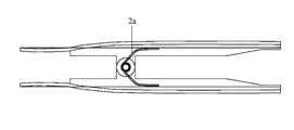
- An example of the spring is a torsion spring 2a as shown in FIG. Thereby, the state which closed the front-end
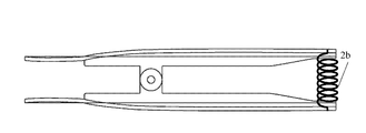
- Embodiment 3 instead of the torsion spring 2a in the second embodiment, a coil spring 2b may be attached to straddle the rear ends of the levers 7 and 8 as shown in FIG.
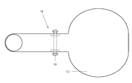
- Embodiment 4 In the mounting tool 16 of this embodiment, the rear end portion of the lever 17 is wider in the direction of the rotation shaft 19 than the front end portion of the lever, as shown in FIG. 11, and the widened area is semicircular. . Further, since the entire lever 17 is formed of a thicker metal plate or plastic than the lever 7 in the first embodiment, no reinforcing margin is provided. Another lever 18 (not shown) has a similar shape. This configuration makes it easier to hold the rear end. Note that both ends of the rotating shaft 19 are crimped.
- the connecting portion 12 has a U shape in a front view, and the ear pads 13 and 14 are located at both ends of the connecting portion 12 to form a disk shape.
- the connecting portion 12 and the ear pads 13 and 14 are both made of the same Ti—Ni shape memory alloy and are integrally processed in a continuous manner. Therefore, there is no fear that the ear pads 13 and 14 are detached from the connecting portion 12 even when used for a long time.
- the earring 21 of this embodiment includes a connecting portion 22 and ear pads 23 and 24 that are processed separately as in the first embodiment.
- the connecting portion 22 is obtained by bending a wire made of a high-strength piano wire having a diameter of 0.5 mm into a U shape.
- the ear pad 23 is made of a substantially disk-shaped metal plate, and has a notch 23b having a width substantially corresponding to the diameter of the wire in the radial direction from the center thereof.
- the ear pad 24 has a notch 24b.
- the one end (other end) of the connection part 22 is welded with the ear pad part 23 (24) in the state fitted by the notch 23b (24b).
- the inner surfaces of the ear pads 23 and 24 are coated with urethane rubber to form the buffer portions 23a and 24a.
- a decoration 15 is attached to the outer surface of the ear pad 23. Unlike the first embodiment, the decoration 15 is also attached to the connecting portion 22.
- the distal end portions of the levers 27 and 28 form an inverted trapezoidal shape in a cross-sectional view in the thickness direction. That is, the inner surfaces of the tip portions facing each other are parallel to the rotation axis, and the outer surface forms an acute angle with the rotation axis.
- the buffer parts 33a, 34a fixed to the inner surfaces of the ear pads 33, 34 facing each other have a cylindrical or drum shape made of urethane rubber.
- the buffer portions 33a and 34a are provided, for example, by punching a rubber sheet into a cylindrical shape with a mold, and chamfering the ridgeline as it is, and then sticking them to the inner surfaces of the ear pad portions 33 and 34 with an adhesive. . Since the surfaces of the buffer portions 33a and 34a that contact the earlobe are flat, the pressure applied to the earlobe is further dispersed. Other elements may be the same as those in the fifth embodiment in terms of traits.
- the inner surface of the rear end of one of the levers 7 (8) of the mounting tool 6 of the first embodiment projects toward the rear end of the other lever 8 (7).
- the spacer to be attached is attached by a known means such as welding or a screw.
- the rear end portions of the levers 7 and 8 cannot be closed narrower than the height of the spacer, and it is possible to further prevent the front end portions from being excessively widened.
Landscapes
- Engineering & Computer Science (AREA)
- Mechanical Engineering (AREA)
- Adornments (AREA)
Priority Applications (4)
| Application Number | Priority Date | Filing Date | Title |
|---|---|---|---|
| US14/908,752 US10085529B2 (en) | 2013-08-01 | 2014-07-08 | Non-pierced earring, and fitting implement for the same |
| CN201480043324.1A CN105828655B (zh) | 2013-08-01 | 2014-07-08 | 耳饰及用于该耳饰的佩戴工具 |
| EP14831916.3A EP3028594B1 (de) | 2013-08-01 | 2014-07-08 | Ohrring und befestigungsvorrichtung dafür |
| JP2015511747A JP5946161B2 (ja) | 2013-08-01 | 2014-07-08 | イヤリングとそのための装着具 |
Applications Claiming Priority (4)
| Application Number | Priority Date | Filing Date | Title |
|---|---|---|---|
| JP2013160081 | 2013-08-01 | ||
| JP2013-160081 | 2013-08-01 | ||
| JP2014105967 | 2014-05-22 | ||
| JP2014-105967 | 2014-05-22 |
Publications (1)
| Publication Number | Publication Date |
|---|---|
| WO2015016012A1 true WO2015016012A1 (ja) | 2015-02-05 |
Family
ID=52431552
Family Applications (1)
| Application Number | Title | Priority Date | Filing Date |
|---|---|---|---|
| PCT/JP2014/068142 Ceased WO2015016012A1 (ja) | 2013-08-01 | 2014-07-08 | イヤリングとそのための装着具 |
Country Status (5)
| Country | Link |
|---|---|
| US (1) | US10085529B2 (de) |
| EP (1) | EP3028594B1 (de) |
| JP (2) | JP5946161B2 (de) |
| CN (1) | CN105828655B (de) |
| WO (1) | WO2015016012A1 (de) |
Cited By (2)
| Publication number | Priority date | Publication date | Assignee | Title |
|---|---|---|---|---|
| JP2017070369A (ja) * | 2015-10-05 | 2017-04-13 | 有限会社清水坂ガラス館 | ピアス状イヤリングの装着具 |
| WO2018142602A1 (ja) * | 2017-02-06 | 2018-08-09 | 有限会社清水坂ガラス館 | ピアス状イヤリングの装着具 |
Families Citing this family (2)
| Publication number | Priority date | Publication date | Assignee | Title |
|---|---|---|---|---|
| JPH0642841B2 (ja) | 1991-10-28 | 1994-06-08 | 株式会社アサヒコーポレーション | スラッシュ成形靴用靴中芯 |
| JP7117039B1 (ja) | 2021-08-03 | 2022-08-12 | 辰男 稲葉 | 装身具 |
Citations (8)
| Publication number | Priority date | Publication date | Assignee | Title |
|---|---|---|---|---|
| US2819595A (en) * | 1954-07-06 | 1958-01-14 | Faye H Northup | Earring with a cushion attachment |
| JPS63131627U (de) * | 1987-02-19 | 1988-08-29 | ||
| JPS63152412U (de) * | 1987-03-27 | 1988-10-06 | ||
| JPH03126598A (ja) | 1989-12-14 | 1991-05-29 | Kotobuki:Kk | 複合筆記具 |
| JPH0681317U (ja) | 1993-05-10 | 1994-11-22 | 株式会社日之出宝飾 | イヤリング |
| JP3084877U (ja) * | 2001-09-25 | 2002-03-29 | 塚越 孝平 | キャッチ付きピアスの取り付け器具 |
| JP3113063U (ja) * | 2005-05-11 | 2005-09-02 | 逸生 礒崎 | ネックレス等の装飾品の連結補助具 |
| JP2011078460A (ja) | 2009-10-03 | 2011-04-21 | Pierring:Kk | クリップ式イヤリング |
Family Cites Families (14)
| Publication number | Priority date | Publication date | Assignee | Title |
|---|---|---|---|---|
| US188323A (en) * | 1877-03-13 | Improvement in ear-rings | ||
| US1436589A (en) * | 1921-08-15 | 1922-11-21 | Ogle B Hopkins | Cotter-pin puller |
| US1707947A (en) * | 1927-04-19 | 1929-04-02 | Zettervall Carl Theodor | Valve-pin pliers |
| US1791567A (en) * | 1928-03-07 | 1931-02-10 | Joseph H Meyer Brothers | Article of jewelry |
| US1978652A (en) * | 1934-03-29 | 1934-10-30 | Edward J Shea | Earring |
| US2510511A (en) * | 1948-03-29 | 1950-06-06 | D E Makepeace Company | Earring |
| US3540106A (en) * | 1968-07-10 | 1970-11-17 | Maurice J Goldman | Brake cable release tool |
| US3739599A (en) * | 1972-06-09 | 1973-06-19 | A Melone | Resilient earring including means limiting pressure on the ear lobe |
| JPS5238260Y2 (de) * | 1973-12-18 | 1977-08-31 | ||
| JPS5419016U (de) * | 1977-07-11 | 1979-02-07 | ||
| JPS57103873U (de) * | 1980-12-16 | 1982-06-26 | ||
| JPS62111874U (de) * | 1985-12-30 | 1987-07-16 | ||
| JP3126598U (ja) | 2006-08-22 | 2006-11-02 | 庄蔵 板倉 | イヤリング |
| CN203074795U (zh) * | 2011-11-25 | 2013-07-24 | 北京迈迪顶峰医疗科技有限公司 | 心耳夹 |
-
2014
- 2014-07-08 JP JP2015511747A patent/JP5946161B2/ja active Active
- 2014-07-08 WO PCT/JP2014/068142 patent/WO2015016012A1/ja not_active Ceased
- 2014-07-08 CN CN201480043324.1A patent/CN105828655B/zh active Active
- 2014-07-08 EP EP14831916.3A patent/EP3028594B1/de not_active Not-in-force
- 2014-07-08 US US14/908,752 patent/US10085529B2/en active Active
-
2016
- 2016-04-21 JP JP2016084944A patent/JP6111395B2/ja active Active
Patent Citations (8)
| Publication number | Priority date | Publication date | Assignee | Title |
|---|---|---|---|---|
| US2819595A (en) * | 1954-07-06 | 1958-01-14 | Faye H Northup | Earring with a cushion attachment |
| JPS63131627U (de) * | 1987-02-19 | 1988-08-29 | ||
| JPS63152412U (de) * | 1987-03-27 | 1988-10-06 | ||
| JPH03126598A (ja) | 1989-12-14 | 1991-05-29 | Kotobuki:Kk | 複合筆記具 |
| JPH0681317U (ja) | 1993-05-10 | 1994-11-22 | 株式会社日之出宝飾 | イヤリング |
| JP3084877U (ja) * | 2001-09-25 | 2002-03-29 | 塚越 孝平 | キャッチ付きピアスの取り付け器具 |
| JP3113063U (ja) * | 2005-05-11 | 2005-09-02 | 逸生 礒崎 | ネックレス等の装飾品の連結補助具 |
| JP2011078460A (ja) | 2009-10-03 | 2011-04-21 | Pierring:Kk | クリップ式イヤリング |
Cited By (2)
| Publication number | Priority date | Publication date | Assignee | Title |
|---|---|---|---|---|
| JP2017070369A (ja) * | 2015-10-05 | 2017-04-13 | 有限会社清水坂ガラス館 | ピアス状イヤリングの装着具 |
| WO2018142602A1 (ja) * | 2017-02-06 | 2018-08-09 | 有限会社清水坂ガラス館 | ピアス状イヤリングの装着具 |
Also Published As
| Publication number | Publication date |
|---|---|
| CN105828655A (zh) | 2016-08-03 |
| US10085529B2 (en) | 2018-10-02 |
| EP3028594A1 (de) | 2016-06-08 |
| EP3028594A4 (de) | 2017-01-25 |
| JP6111395B2 (ja) | 2017-04-12 |
| CN105828655B (zh) | 2018-03-30 |
| US20160166019A1 (en) | 2016-06-16 |
| EP3028594B1 (de) | 2018-09-05 |
| JPWO2015016012A1 (ja) | 2017-03-02 |
| JP5946161B2 (ja) | 2016-07-05 |
| JP2016129786A (ja) | 2016-07-21 |
Similar Documents
| Publication | Publication Date | Title |
|---|---|---|
| JP6111395B2 (ja) | イヤリングとイヤリング装着具との組合せセット | |
| JP5461456B2 (ja) | イヤリング | |
| US5454829A (en) | Pierced ear lobe saver | |
| JP4592116B1 (ja) | クリップ式イヤリング | |
| JP6595286B2 (ja) | ピアス状イヤリングの装着具 | |
| JP3139659U (ja) | クリップ式イヤリング | |
| JP3130993U (ja) | クリップ式イヤリング | |
| JP6587307B2 (ja) | ピアス状イヤリングの装着具 | |
| JP2016043109A (ja) | 耳用装身具 | |
| GB2572067A (en) | Stud earring | |
| JP5419227B2 (ja) | 止め具、止め装置、及び、これを用いた装身具 | |
| EP1811330A1 (de) | Zubehör | |
| JPH0810017A (ja) | 装身用ピアス | |
| US20050223741A1 (en) | Flexible material clutch for a decorative piece | |
| JP3202953U (ja) | イヤリングおよびイヤリングの留め具 | |
| KR102891119B1 (ko) | 이어 링 | |
| WO2009009517A1 (en) | Jewelry adapter | |
| KR101512106B1 (ko) | 각도조절이 가능한 귀걸이 체결구 | |
| JP3158448U (ja) | クリップ式イヤリング | |
| JP3193724U (ja) | 指輪 | |
| JP3181472U (ja) | イヤリング用弾性具及びこれを備えたイヤリング | |
| JP3233026U (ja) | イヤーカフ | |
| JP6337033B2 (ja) | 開閉指輪の止着固定構造とその指輪の製造方法 | |
| JP2017148123A (ja) | 耳用装身具 | |
| KR200325455Y1 (ko) | 귀걸이의 단위체 결합구조 |
Legal Events
| Date | Code | Title | Description |
|---|---|---|---|
| ENP | Entry into the national phase |
Ref document number: 2015511747 Country of ref document: JP Kind code of ref document: A |
|
| 121 | Ep: the epo has been informed by wipo that ep was designated in this application |
Ref document number: 14831916 Country of ref document: EP Kind code of ref document: A1 |
|
| WWE | Wipo information: entry into national phase |
Ref document number: 14908752 Country of ref document: US |
|
| NENP | Non-entry into the national phase |
Ref country code: DE |
|
| WWE | Wipo information: entry into national phase |
Ref document number: 2014831916 Country of ref document: EP |