WO2015016172A1 - Système d'endoscope et procédé d'utilisation d'un système endoscopique - Google Patents
Système d'endoscope et procédé d'utilisation d'un système endoscopique Download PDFInfo
- Publication number
- WO2015016172A1 WO2015016172A1 PCT/JP2014/069806 JP2014069806W WO2015016172A1 WO 2015016172 A1 WO2015016172 A1 WO 2015016172A1 JP 2014069806 W JP2014069806 W JP 2014069806W WO 2015016172 A1 WO2015016172 A1 WO 2015016172A1
- Authority
- WO
- WIPO (PCT)
- Prior art keywords
- light
- light emitting
- period
- colors
- led
- Prior art date
- Legal status (The legal status is an assumption and is not a legal conclusion. Google has not performed a legal analysis and makes no representation as to the accuracy of the status listed.)
- Ceased
Links
Images

Classifications
-
- A—HUMAN NECESSITIES
- A61—MEDICAL OR VETERINARY SCIENCE; HYGIENE
- A61B—DIAGNOSIS; SURGERY; IDENTIFICATION
- A61B1/00—Instruments for performing medical examinations of the interior of cavities or tubes of the body by visual or photographical inspection, e.g. endoscopes; Illuminating arrangements therefor
- A61B1/06—Instruments for performing medical examinations of the interior of cavities or tubes of the body by visual or photographical inspection, e.g. endoscopes; Illuminating arrangements therefor with illuminating arrangements
- A61B1/0661—Endoscope light sources
- A61B1/0684—Endoscope light sources using light emitting diodes [LED]
-
- A—HUMAN NECESSITIES
- A61—MEDICAL OR VETERINARY SCIENCE; HYGIENE
- A61B—DIAGNOSIS; SURGERY; IDENTIFICATION
- A61B1/00—Instruments for performing medical examinations of the interior of cavities or tubes of the body by visual or photographical inspection, e.g. endoscopes; Illuminating arrangements therefor
- A61B1/00002—Operational features of endoscopes
- A61B1/00004—Operational features of endoscopes characterised by electronic signal processing
- A61B1/00009—Operational features of endoscopes characterised by electronic signal processing of image signals during a use of endoscope
-
- A—HUMAN NECESSITIES
- A61—MEDICAL OR VETERINARY SCIENCE; HYGIENE
- A61B—DIAGNOSIS; SURGERY; IDENTIFICATION
- A61B1/00—Instruments for performing medical examinations of the interior of cavities or tubes of the body by visual or photographical inspection, e.g. endoscopes; Illuminating arrangements therefor
- A61B1/06—Instruments for performing medical examinations of the interior of cavities or tubes of the body by visual or photographical inspection, e.g. endoscopes; Illuminating arrangements therefor with illuminating arrangements
- A61B1/0638—Instruments for performing medical examinations of the interior of cavities or tubes of the body by visual or photographical inspection, e.g. endoscopes; Illuminating arrangements therefor with illuminating arrangements providing two or more wavelengths
-
- A—HUMAN NECESSITIES
- A61—MEDICAL OR VETERINARY SCIENCE; HYGIENE
- A61B—DIAGNOSIS; SURGERY; IDENTIFICATION
- A61B1/00—Instruments for performing medical examinations of the interior of cavities or tubes of the body by visual or photographical inspection, e.g. endoscopes; Illuminating arrangements therefor
- A61B1/06—Instruments for performing medical examinations of the interior of cavities or tubes of the body by visual or photographical inspection, e.g. endoscopes; Illuminating arrangements therefor with illuminating arrangements
- A61B1/0655—Control therefor
-
- A—HUMAN NECESSITIES
- A61—MEDICAL OR VETERINARY SCIENCE; HYGIENE
- A61B—DIAGNOSIS; SURGERY; IDENTIFICATION
- A61B1/00—Instruments for performing medical examinations of the interior of cavities or tubes of the body by visual or photographical inspection, e.g. endoscopes; Illuminating arrangements therefor
- A61B1/06—Instruments for performing medical examinations of the interior of cavities or tubes of the body by visual or photographical inspection, e.g. endoscopes; Illuminating arrangements therefor with illuminating arrangements
- A61B1/0661—Endoscope light sources
- A61B1/0669—Endoscope light sources at proximal end of an endoscope
-
- G—PHYSICS
- G02—OPTICS
- G02B—OPTICAL ELEMENTS, SYSTEMS OR APPARATUS
- G02B23/00—Telescopes, e.g. binoculars; Periscopes; Instruments for viewing the inside of hollow bodies; Viewfinders; Optical aiming or sighting devices
- G02B23/24—Instruments or systems for viewing the inside of hollow bodies, e.g. fibrescopes
- G02B23/2407—Optical details
- G02B23/2461—Illumination
-
- G—PHYSICS
- G02—OPTICS
- G02B—OPTICAL ELEMENTS, SYSTEMS OR APPARATUS
- G02B27/00—Optical systems or apparatus not provided for by any of the groups G02B1/00 - G02B26/00, G02B30/00
- G02B27/10—Beam splitting or combining systems
- G02B27/1006—Beam splitting or combining systems for splitting or combining different wavelengths
Definitions
- the present invention relates to an endoscope system including a light source device that emits light by supplying a drive current to light emitting elements of a plurality of colors, and an operation method of the endoscope system.
- xenon lamps and the like have been used as a light source device for illumination light irradiating a subject from an endoscope.
- LEDs light emitting elements such as LEDs are considered in consideration of low power consumption and durability. Those that use the have been put into practical use.
- Such a light source device (surface sequential system) having a red LED (R-LED), a green LED (G-LED), a blue LED (B-LED), and a violet LED (V-LED) as a light emitting element.
- R-LED red LED
- G-LED green LED
- B-LED blue LED
- V-LED violet LED
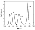
- FIG. 10 is a timing chart of the conventional LED lighting control when performing normal observation with the maximum light amount
- FIG. 11 is a diagram showing a spectral spectrum when performing the conventional LED lighting control shown in FIG. It is.
- One frame is equally divided into three fields, and one field is divided into an exposure period and a readout period.
- the LED corresponding to the field is lit at all times during the exposure period, and pulse width modulation (PWM) is not performed.
- PWM pulse width modulation
- the green LED supplies the maximum rated current Igmax as a current because the light emission efficiency is lower in the current technology than the LEDs of other colors (see FIG. 10).
- the red LED, the blue LED, and the violet LED are set to current values that can achieve color balance with respect to the light emission amount of the green LED.
- other color LEDs having higher luminous efficiency than the green LED are supplied with current values less than the maximum rated currents Irmax, Ibmax, and Ivmax.
- FIG. 11 shows an example in which the relative emission intensity of light emitted from each color LED at this time is shown as a spectral spectrum.
- the light emission luminance (brightness) in such a light source device can be adjusted, for example, by increasing or decreasing the drive current value supplied to each color LED or by performing the above-described pulse width modulation.
- paragraph [0084] of Japanese Patent Application Laid-Open No. 2011-36361 discloses a method for changing the color tone without changing the emitted light amount of each light source. It is described that the color tone of illumination light is changed in a pseudo manner by changing the exposure time of the image sensor 21 at each lighting timing. More specifically, each light source and the image sensor are controlled synchronously so that only the first light source such as a blue laser light source is turned on and the exposure time of the image sensor for imaging and only the second light source such as a white light source is turned on. Each exposure time is adjusted to increase or decrease individually with respect to the exposure time for imaging, and the obtained captured images are combined to form observation image data. Therefore, it is considered that the color tone change in this publication is performed by a so-called element shutter.
- the light source unit 22 is red.
- the adjustment of the duty ratio is performed by the light receiving unit 26 that measures the emitted light amount of the first to third LEDs 22a to 22c and the LED driver 21, and the reference voltage variable unit 21a sets the emitted light amount set by the user.
- the red color emitted from the first LED 22a In response to the instruction signal related to the value, the red color emitted from the first LED 22a, the green color emitted from the second LED 22b, and the third LED 22c. As the blue intensity ratio of the emanating it is constant, it is described that calculates the first to third reference voltages V1-V3.
- the light from the first to third LEDs 22a to 22c is received by the light receiving unit 26 in paragraph [0050] of Japanese Patent Application Laid-Open No. 2010-158415 described above. It is described that information on the amount of emitted light is received and the amount of emitted light due to aging, temperature change, etc. is taken into account, and the drive amount of the first to third LEDs 22a to 22c and thus the amount of emitted light are adjusted accurately. Yes.
- the amount of green light is less than the target amount of light (for example, the amount of light when a xenon lamp is used as a light source). That is, a light source device that performs surface sequential illumination using light emitting elements such as LEDs is desired to improve light emission luminance (brightness).
- the driving current supplied to obtain the same light emission intensity may change due to, for example, temperature or other factors, and the light emission wavelength and light emission intensity may vary due to deterioration over time. Therefore, it is desirable to be able to cope with these.
- the present invention has been made in view of the above circumstances, and provides an endoscope system including a frame sequential light source device using a light emitting element capable of increasing the maximum light emission amount, and an operation method of the endoscope system. It is intended to provide.
- An endoscope system includes a light emitting element of a plurality of colors, a light emitting element driving unit that supplies a driving current to the light emitting elements of the plurality of colors to emit light, and a control unit that controls the light emitting element driving unit.
- a light source device comprising: an endoscope that irradiates a subject with illumination light generated by the light source device and captures an optical image of the subject; and an imaging device that captures the optical image of the subject; An image picked up by the image pickup device is processed, and the ratio of each maximum emission intensity of the light emitting elements of the plurality of colors and a color balance value indicating a light amount ratio required for the light of the plurality of colors.
- a video processor for setting each maximum light emission period of the light emitting elements of the plurality of colors within one frame period of frame sequential illumination, and the control unit includes the video processor during the light emission period within the maximum light emission period. Multiple Light from the light emitting element and controls the light emitting device driving unit so as to face serial manner emission of.
- a method for operating an endoscope system in which a light emitting element driving unit of a light source device supplies driving current to light emitting elements of a plurality of colors to emit light, and a control unit of the light source device emits the light emission. Controlling the element driving unit, the endoscope irradiating the subject with illumination light generated by the light source device to capture the optical image of the subject, and the imaging element capturing the optical image of the subject;
- a video processor processes an image picked up by the image pickup device, and each maximum emission intensity of the light emitting devices of the plurality of colors and a color balance value indicating a light amount ratio required for the light of the plurality of colors for each color.
- each maximum light emission period of the light emitting elements of the plurality of colors within one frame period of frame sequential illumination is set, and the control unit is configured to emit light from the light emitting elements of the plurality of colors during the light emission period within the maximum light emission period Light comes out in a surface sequence It is an operation method of the endoscope system and controls the light emitting device driving unit so as to.
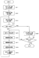
- FIG. 9 is a flowchart showing exposure period setting processing by the video processor in the first embodiment.
- the timing chart which shows the light emission timing of each color LED when performing the field sequential illumination of narrow band light observation mode.
- the block diagram which shows the structure of the endoscope system of Embodiment 2 of this invention.
- the chart which shows an example of the lookup table memorize
- FIG. 9 is a flowchart showing an automatic light control process that maintains color balance in the second embodiment.
- FIG. 11 is a diagram showing a spectrum when the conventional LED lighting control shown in FIG. 10 is performed.
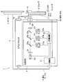
- FIG. 1 is a diagram showing a configuration of an endoscope system.
- the endoscope system 1 includes a scope 2, a light source device 3, a video processor 4, a monitor 5, and a communication cable 6.
- the light source device 3 has a plurality of color light emitting elements as light sources, specifically, a red LED (R-LED) 23r that is a red (R) light emitting element and a green LED (G-LED) that is a green (G) light emitting element. ) 23g, a blue LED (B-LED) 23b which is a blue (B) light emitting element, and a violet LED (V-LED) 23v which is a violet (V) light emitting element.
- R-LED red LED
- G-LED green LED
- B-LED blue LED
- V-LED violet LED
- the light emitted from these light emitting elements can constitute white light, and in this embodiment, the red, green and blue color bands, which are the three primary color bands constituting white light,
- the light emitted from the red LED 23r constitutes the red band
- the light emitted from the green LED 23g constitutes the green band
- the light emitted from the blue LED 23b and the narrow band light emitted from the violet LED 23v constitute the blue band. (See also FIG. 11).
- the violet LED 23v in the present embodiment is for performing such narrow-band light observation (Narrow Band Imaging: NBI (registered trademark)), and emits narrow-band light with a wavelength of, for example, 390 to 445 nm. ing.
- NBI Near Band Imaging
- the green LED 23g of the present embodiment emits this narrow band light, and also serves as a narrow band light emitting element.
- the endoscope system 1 of the present embodiment can be set to an observation mode including a white light observation mode and a narrow band light observation mode.
- the LED drive unit 22 provided in the light source device 3 supplies and drives the red LED 23r, the green LED 23g, the blue LED 23b, and the violet LED 23v.
- the control unit 21 provided in the light source device 3 controls the LED driving unit 22 so as to adjust the emission intensity and the emission period of the emitted light of each of the red LED 23r, the green LED 23g, the blue LED 23b, and the violet LED 23v.
- the control of the control unit 21 is performed based on the exposure period acquired by communicating with the video processor 4 via the communication cable 6 and information on the current brightness value of the subject.
- the light source device 3 is provided with four collimator lenses 24, three dichroic filters 25a, 25b, and 25c, and one condenser lens 26 as an optical system for transmitting illumination light.
- the four collimator lenses 24 are arranged on the optical path of the emitted light of each of the red LED 23r, the green LED 23g, the blue LED 23b, and the violet LED 23v, and emits the incident light as parallel light.
- the first dichroic filter 25a transmits the red light R from the red LED 23r and reflects the green light G from the green LED 23g.
- the second dichroic filter 25b transmits the red light R from the red LED 23r and the green light G from the green LED 23g, and reflects the blue light B from the blue LED 23b.
- the third dichroic filter 25c transmits the red light R from the red LED 23r, the green light G from the green LED 23g, and the blue light B from the blue LED 23b, and reflects the violet color narrow-band light V from the violet LED 23v. Is.
- the condensing lens 26 condenses the parallel light beam from the third dichroic filter 25 c on the incident end face of the base end of the light guide 11 of the scope 2.
- An operation panel 28 provided in the light source device 3 is for a user to perform an operation on the light source device 3.
- the power on / off operation of the light source device 3, the white light observation mode and the narrowband light described above are performed.
- An operation for setting an observation mode such as an observation mode can be performed.
- the observation mode input from the operation panel 28 is transmitted to the video processor 4 via the control unit 21 and the communication cable 6, and image processing corresponding to the observation mode is performed.
- the scope 2 which is an endoscope that receives illumination light from the light source device 3, includes a light guide 11, a lens 12, a CCD 13, a scope ID storage unit 14, a light guide connector 15, and a video connector 16. And.
- the light guide 11 has a base end extending from the light guide connector 15, and when the light guide connector 15 is connected to the light source device 3, the light guide 11 is connected to the incident end surface of the light guide 11 from the condenser lens 26 described above. Light is collected.
- the light guide 11 is inserted through the insertion portion of the scope 2 to the tip, and emits illumination light from the exit surface of the tip.
- An illumination lens 12 is disposed on the optical path of the illumination light at the distal end of the scope 2.
- the illumination light from the light source device 3 transmitted through the light guide 11 is irradiated to the subject from the distal end of the insertion portion via the lens 12.
- the optical image of the subject irradiated with the illumination light is taken in through an objective lens (not shown) disposed at the distal end of the insertion portion of the scope 2 and formed on the CCD 13 that is an image sensor.
- the CCD 13 is a monochrome image pickup device that receives field sequential illumination light (in contrast, if it is a simultaneous illumination type, it is a color image pickup device provided with a color filter array or the like).
- the CCD 13 performs imaging to convert an optical image of the subject into an electrical signal, and transmits the electrical signal to the video processor 4 to which the video connector 16 is connected via a signal line.
- the CCD 13 is used as the image sensor, but the present invention is not limited to this, and a CMOS or other image sensor may be used.
- the scope ID storage unit 14 is a storage unit that stores the identification information of the scope 2 in a nonvolatile manner.
- the scope ID storage unit 14 stores information such as a product model number and manufacturing serial number of the scope 2, a time required for reading out the CCD 13, and a color balance value indicating a light amount ratio required for light of a plurality of colors.
- the color balance values are the RGB light quantity ratios RCr, RCg, RCb required in the white light observation mode by the imaging system of the scope 2 (CCD 13, objective lens, etc.) and the GV required in the narrow band light observation mode.
- Light intensity ratios RNg and RNv that is, the color balance value is determined for each observation mode, and when there is another observation mode, it is also determined for that observation mode). . That is, the sensitivity of the photodiodes configured in each pixel of the CCD 13 that is a monochrome image sensor varies depending on the band of light received, and the received light is in the red band even if the same amount of light is received. The amount of generated charge differs between the case of the green band and the case of the blue band. Further, since the image displayed on the monitor 5 is observed by the human eye, it is necessary to have a color balance that matches the human eye.
- the RGB light quantity ratios RCr, RCg, and RCb are used to generate charges in a color balance (white balance in the white light observation mode) with these various elements taken into consideration. This is a value indicating the ratio of the amount of light to be received in the blue band.
- the GV light quantity ratios RNg and RNv are used to generate charges in a color balance in the narrowband light observation mode (here, a color balance between green and violet colors). Are values indicating the ratio of the amount of light to be received.
- Information stored in the scope ID storage unit 14 is read out by the video processor 4 through a signal line.
- the video processor 4 generates a color image signal by synchronizing the color images received from the CCD 13, performs signal processing such as color balance adjustment, gamma conversion, and color conversion, and then displays a signal format for display on the monitor 5. And output to the monitor 5.
- the video processor 4 has, for example, three rows 3 of three input components (R component, G component, (B + V) component) and three output components (R component, G component, B component).
- Image processing for generating a white light observation image is performed using a matrix of columns.
- the video processor 4 uses, for example, a 3 ⁇ 2 matrix of two input components (G component, V component) and three output components (R component, G component, B component). Then, image processing for generating a narrow-band light observation image is performed. That is, in the narrow-band light observation mode, even if there are two color components obtained from the CCD 13, the image displayed on the monitor 5 is a three-color display image.
- the video processor 4 extracts, for example, a luminance signal from each received color image, and generates information on the current brightness value based on the extracted luminance signal. Information on the current brightness value thus generated by the video processor 4 is transmitted to the control unit 21 of the light source device 3 via the communication cable 6 connecting the video processor 4 and the light source device 3.
- the control unit 21 controls the light emission intensity of each color LED through the LED driving unit 22 based on the received information on the current brightness value as described above. Further, the control unit 21 acquires the color balance value stored in the scope ID storage unit 14 via the video processor 4 and adjusts the color balance of the illumination light, that is, in the white light observation mode, the red LED 23r.
- the balance adjustment of the emission intensity of the green LED 23g, the blue LED 23b, and the violet LED 23v, and the balance adjustment of the emission intensity of the green LED 23g and the violet LED 23v are performed in the narrow-band light observation mode, respectively. As described above, when an image in the blue band in the white light observation mode is acquired, both the blue LED 23b and the violet LED 23v are caused to emit light. It is possible to provide a margin for the amount of emitted light.
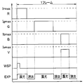
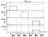
- FIG. 2 is a timing chart showing the light emission timing of each color LED when performing surface sequential illumination in the white light observation mode.
- the CCD 13 alternately performs an operation in an exposure period in which light is received and charges are accumulated, and an operation in a readout period in which the accumulated charges are sequentially read out for each pixel.
- exposure is performed by causing any one band of LEDs to emit light during the exposure period, and all the LEDs are extinguished during the readout period.
- the video processor 4 when starting exposure of one frame, the video processor 4 outputs a frame start signal WSP (see FIG. 2) to the light source device 3 and indicates an exposure period (that is, a maximum light emission period of the LED).
- An LED lighting control signal EXP (see FIG. 2), which is a light emitting element lighting control signal, is output.
- the light source device 3 detects the rise of the frame start signal WSP, for example, only the red LED 23r emits light during the exposure period of the first field in one frame in which the LED lighting control signal EXP is high. Thereby, the CCD 13 performs exposure by receiving the red light R from the illuminated subject.
- the light source device 3 detects that the exposure period of the first field has ended, and turns off all the LEDs.
- the video processor 4 shifts to a reading period after the exposure period ends, and reads the R image obtained by exposing the red light R from the CCD 13.
- the video processor 4 shifts to the exposure period of the second field and sets the LED lighting control signal EXP to high. For example, only the green LED 23g emits light during the second field exposure period in which the LED lighting control signal EXP is high. As a result, the CCD 13 performs exposure by receiving the green light G from the illuminated subject.
- the light source device 3 detects that the exposure period of the second field has ended, and turns off all the LEDs.
- the video processor 4 shifts to a reading period after the exposure period ends, and reads the G image obtained by exposing the green light G from the CCD 13.
- the video processor 4 shifts to the exposure period of the third field and sets the LED lighting control signal EXP to high. For example, only the blue LED 23b and the violet LED 23v emit light during the third field exposure period in which the LED lighting control signal EXP is high. As a result, the CCD 13 performs exposure by receiving the blue light B and the narrow band light V from the illuminated subject.
- the light source device 3 detects that the exposure period of the third field has ended, and turns off all the LEDs.
- the video processor 4 shifts to a reading period after the exposure period ends, and reads the BV image obtained by exposing the blue light B and the narrow band light V from the CCD 13.
- the light source device 3 After detecting the rising edge of the frame start signal WSP, the light source device 3 follows a predetermined order according to the period during which the LED lighting control signal EXP is high, in this case, R ⁇ G ⁇ (B + V). Emits light in order.
- the exposure period of each color that is, the maximum light emission period of each color LED is different for each color.
- the setting of the maximum light emission period is performed so that the maximum light emission amount can be obtained when the light emission luminance of each color LED is maximized (thus, compared to the case where a field is formed by dividing one frame into three equal parts. Also, the maximum light emission amount of the light source device 3 increases).
- FIG. 3 is a flowchart showing exposure period setting processing by the video processor 4.
- the video processor 4 obtains the type information of the scope 2 from the scope ID storage unit 14 and information related to the imaging system, that is, the time required for reading the CCD 13 (reading period), as described above. Information such as a color balance value in the white light observation mode is acquired (step S1).
- the video processor 4 communicates with the light source device 3 to emit light when the maximum light emission intensity of each color LED (the maximum rated currents Irmax, Igmax, Ibmax, and Ivmax are supplied to the respective color LEDs 23r, 23g, 23b, and 23v). (Strength) information is acquired (step S2).
- the video processor 4 subtracts three fields of the readout period Tf acquired in step S1 from one frame period TF to calculate the total exposure period Texp in one frame as in the following Equation 1 (step 1) S3).
- the ratio of the emission intensity of the violet LED 23v and the blue LED 23b is constant (however, the constant ratio is such that the light intensity of B> the light intensity of V is satisfied), and the blue LED 23b has the maximum rated current.
- the maximum light emission period Tr of the red light emitting element part red LED 23r
- the maximum light emission period Tg of the green light emitting element part green LED 23g
- the blue light emitting element part blue LED 23b and violet LED 23v corresponding to the exposure period of each color
- Tr ⁇ kr / (kr + kg + kb) ⁇ ⁇ Texp
- Tg ⁇ kg / (kr + kg + kb) ⁇ ⁇ Texp
- Tb ⁇ kb / (kr + kg + kb) ⁇ ⁇ Texp
- FIG. 2 described above shows waveforms when the currents Irmax, Igmax, Ibmax, and Ivmax are supplied.
- each color LED emits light at the maximum light emission intensity in all exposure periods (that is, all periods in which light emission is possible except the readout period), and the color balance of the surface sequential illumination light is in a state of being balanced.
- the light emitting ability of each color LED can be utilized to the maximum.
- FIG. 4 is a timing chart showing the light emission timing of each color LED when performing frame sequential illumination in the narrow-band light observation mode.
- the video processor 4 when starting exposure of one frame, the video processor 4 outputs a frame start signal WSP (see FIG. 4) to the light source device 3, and a light emitting element indicating an exposure period An LED lighting control signal EXP (see FIG. 4) which is a lighting control signal is output.
- WSP frame start signal
- EXP LED lighting control signal
- the light source device 3 detects the rising edge of the frame start signal WSP, for example, only the violet LED 23v is caused to emit light during the exposure period of the first field in one frame in which the LED lighting control signal EXP is high.
- the CCD 13 performs exposure by receiving the narrow-band light V from the illuminated subject.
- the light source device 3 detects that the exposure period of the first field has ended, and turns off all the LEDs.
- the video processor 4 shifts to a reading period after the exposure period ends, and reads the V image obtained by exposing the narrow band light V from the CCD 13.
- the video processor 4 shifts to the exposure period of the second field and sets the LED lighting control signal EXP to high. For example, only the green LED 23g emits light during the second field exposure period in which the LED lighting control signal EXP is high. As a result, the CCD 13 performs exposure by receiving the green light G from the illuminated subject.
- the light source device 3 detects that the exposure period of the second field has ended, and turns off all the LEDs.
- the video processor 4 shifts to a reading period after the exposure period ends, and reads the G image obtained by exposing the green light G from the CCD 13.
- the light source device 3 After the light source device 3 detects the rising edge of the frame start signal WSP, the light source device 3 emits light in a predetermined order, here in the order of V ⁇ G, in accordance with the period during which the LED lighting control signal EXP is high. Do.
- the exposure period setting method for obtaining the maximum light emission amount in the narrow-band light observation mode is almost the same as that in the white light observation mode described above, and is performed by the process shown in FIG.
- the video processor 4 when the video processor 4 is set to the narrowband light observation mode, the information related to the imaging system, that is, the time required for reading the CCD 13 (readout period) from the scope ID storage unit 14, the narrowband light observation mode described above. Information such as a color balance value is acquired (step S1).
- the video processor 4 communicates with the light source device 3 to acquire information on the maximum emission intensities Lg and Lv of the green LED 23g and the violet LED 23v used for narrowband light observation (step S2).
- the video processor 4 subtracts two fields of the readout period Tf acquired in step S1 from one frame period TNF in the narrow-band light observation mode, so that the total exposure period TNexp in one frame in the narrow-band light observation mode. Is calculated as shown in Equation 4 below (step S3).
- TNexp TNF-2 ⁇ Tf
- RNg and RNv which are the color balance values acquired in step S1
- Lg of the green LED 23g and the maximum emission intensity Lv of the violet LED 23v acquired in step S2 the exposure period of each narrow band.
- the ratios kNg and kNv are calculated as shown in Equation 5 below (step S4).
- TNg ⁇ kNg / (kNg + kNv) ⁇ ⁇ TNexp
- TNv ⁇ kNv / (kNg + kNv) ⁇ ⁇ TNexp
- the light source device 3 is the current input from the video processor 4. Based on the information on the brightness value, automatic light control is performed.
- each color LED is controlled by pulse width modulation (PWM) within the maximum light emission period of each color, or the drive current supplied to each color LED is controlled, or a combination thereof is used. good.
- PWM pulse width modulation
- the light source device 3 transmits the end timing of the light emission period of each color LED to the video processor 4 in order to improve the frame rate. Also good.
- the video processor 4 notifies the light source device 3 of the start timing of the exposure period of each field, and in response to this notification, the light source device 3 causes any color LED corresponding to the field to emit light. Then, the current light emission amount (this light emission amount is obtained, for example, by integrating the light emission intensity associated with the drive current with time, or an illuminance sensor or the like is provided for each color LED, and the sensor value is The light source device 3 notifies the video processor 4 of the end timing of the light emission period when the required light emission amount is reached.
- the video processor 4 When the video processor 4 receives the end timing of the light emission period, it immediately shifts to the reading period without waiting for the end of the exposure period at the maximum light amount. When the reading period ends, the video processor 4 notifies the light source device 3 of the start timing of the exposure period of the next field, as described above.
- the frame rate can be improved by repeating such processing. For example, since the distance from the distal end of the insertion part of the scope 2 to the subject is short during near-point observation, the amount of illumination light is considered to be small. Therefore, there is an advantage that the frame rate can be improved in such a case.
- the CCD 13 serving as the image pickup device is disposed at the distal end of the insertion portion of the scope 2.
- the present invention is not limited to this configuration, and an optical image is transmitted via a relay optical system or the like. Or you may be the structure which images in a video processor. Therefore, the image sensor is not necessarily included in the endoscope.
- the conventional driving method as shown in FIG. the maximum light emission amount can be increased.
- the light emission elements of each color emit light at the maximum light emission intensity during the entire period in which the light emission elements of each color can emit light in a color balanced state. It can be used to the fullest. Thereby, the light quantity shortage of green light when using LED as a light source can be improved, and it can approach the light quantity when using a xenon lamp as a light source.
- the frame rate is improved when the light source device 3 notifies the video processor 4 of the end timing of the light emission period. Can do.
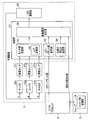
- FIG. 5 is a block diagram showing the configuration of the endoscope system.
- the illustration and description of the configuration related to the violet LED 23v and the violet LED 23v are omitted for the sake of simplicity, but the following description is similarly applied even when the violet LED 23v is provided. be able to.
- automatic light control is performed by controlling the drive current supplied to each color LED within the above-described maximum light emission period.
- the light source device 3 of the present embodiment includes an illuminance sensor 27 r that detects the light emission intensity of the red LED 23 r and a green LED 23 g as a light emission intensity detection unit that detects the light emission intensity of the light emitting elements of multiple colors.
- An illuminance sensor 27g for detecting the emission intensity of the blue LED 23 and an illuminance sensor 27b for detecting the emission intensity of the blue LED 23b are provided.
- These illuminance sensors 27r, 27g, and 27b detect positions (for example, the respective color LEDs 23r, 23g, and 27b) that detect leakage light that does not reach the incident end surface of the light guide 11 among the light beams emitted from the respective color LEDs 23r, 23g, and 23b. 23b).
- the illuminance sensors 27r, 27g, and 27b output the result of detecting the light intensity to the control unit 21.
- the control unit 21 includes a sensor value storage unit 31 having an LUT storage unit 32, a color balance value holding unit 33, a target brightness setting unit 34, and a drive current setting unit 35.
- the sensor value storage unit 31 stores sensor values obtained as a result of detection by the illuminance sensors 27r, 27g, and 27b described above.
- the LUT storage unit 32 gradually changes the drive currents Ir, Ig, and Ib of the respective color LEDs 23r, 23g, and 23b from the minimum rated current to the maximum rated current, and sets sensor values obtained from the illuminance sensors 27r, 27g, and 27b.
- This look-up table is not limited to holding data stored at the time of manufacture, but at an appropriate update timing, for example, when the endoscope system 1 (more specifically, the light source device 3) is turned on. Alternatively, it may be updated when the color balance value set in the color balance value holding unit 33 is changed.
- the LUT storage unit 32 is configured as a rewritable storage unit.
- the color balance value holding unit 33 stores and holds the color balance value read from the scope ID storage unit 14 by the video processor 4.
- the target brightness setting unit 34 holds a target brightness value to be reached by information on the current brightness value generated and output by the video processor 4.
- the drive current setting unit 35 reads the color balance value read from the color balance value holding unit 33, the target brightness value read from the target brightness setting unit 34, and the current brightness value received from the video processor 4. Based on the reference result of the lookup table stored in the LUT storage unit 32 of the sensor value storage unit 31, the current brightness value becomes the target brightness value, and the light of multiple colors is Automatic dimming is performed to set the drive currents of the light emitting elements of a plurality of colors so that the light quantity ratio becomes the light quantity ratio indicated by the color balance value.
- FIG. 7 is a flowchart showing the automatic light control process while maintaining the color balance.
- the light source device 3 acquires the color balance value from the scope ID storage unit 14 via the video processor 4 and stores the color balance value in the color balance value holding unit 33.
- the drive current setting unit 35 acquires CBr and CBb as color balance values from the color balance value holding unit 33 (step S11).
- the drive current setting unit 35 acquires the target brightness value BR0 from the target brightness setting unit 34 (step S12).
- the drive current setting unit 35 acquires the current brightness value BRC from the video processor 4 (step S13).
- the drive current setting unit 35 determines whether or not the target brightness value BR0 is equal to the current brightness value BRC (step S14).
- the drive current setting unit 35 acquires the sensor value Sg of the current G illuminance sensor 27g via the sensor value storage unit 31 (step S15).
- Sg x (BR0 / BRC)
- the drive current Ig to be supplied to the green LED 23g from which the sensor value is obtained is obtained by referring to the lookup table in the LUT storage unit 32 (step S16).
- the obtained drive current Ig is 10 (see FIG. 6).
- This sensor value Sr is 80 here.
- the sensor value Sb of the obtained illuminance sensor 27b for B is calculated.
- This sensor value Sb is 130 here.
- the drive current supplied to each color LED is obtained based on Ig and Sg related to the green LED 23g.
- the drive currents Ig, Ir, and Ib obtained in steps S16 to S18 are supplied to the respective color LEDs 23r, 23g, and 23b to emit light (step S19).
- step S14 when it is determined in step S14 that the target brightness value BR0 and the current brightness value BRC are equal, the drive current setting unit 35 sends the current illuminance sensors via the sensor value storage unit 31.
- the sensor values Sr, Sg, and Sb of 27r, 27g, and 27b are acquired (step S20), and it is determined whether or not the color balance is obtained (step S21).
- the same effects as those of the first embodiment described above can be obtained, and not only the color balance is maintained when the light is emitted with the maximum light amount, but also when the light is adjusted to appropriately change the light amount. It is possible to maintain the color balance.
- the drive current to each color LED at the time of dimming is obtained, so the responsiveness can be improved.
- the drive current supplied to the other light emitting elements is obtained based on the light emitting element having the lowest light emitting efficiency (that is, the green LED 23g in this case), the light amount of the light emitting element having the lowest light emitting efficiency is insufficient. It is possible to prevent a situation where color balance cannot be achieved.
- FIG. 8 is a block diagram showing the configuration of the endoscope system.
- automatic dimming is performed by controlling the drive current supplied to each color LED, but in this embodiment, the light emission period of each color LED is adjusted by pulse width modulation within the maximum light emission period.
- Automatic light control is performed, and further, an element shutter is also used as needed to control the exposure time (in this embodiment, an element shutter is also used in combination). Therefore, the entire exposure period other than the readout period is not always used for exposure of the CCD 13. Therefore, in the present embodiment, the actual exposure time within the “exposure period” is defined as the “exposure time”.
- the configuration of the light source device 3 of the present embodiment is substantially the same as that shown in FIG. 5 of the second embodiment described above, but the LUT storage unit 32 is not provided in the sensor value storage unit 31 (however, Of course, when dimming is performed based on both the LED emission period and the drive current, the LUT storage unit 32 may be provided.
- the light source device 3 holds the target brightness value, and the current brightness value is transmitted from the video processor 4 to the light source device 3. The difference between the target brightness value and the current brightness value is transmitted to the drive current setting unit 35 of the light source device 3. For this reason, the target brightness setting unit 34 is not provided in the light source device 3 of the second embodiment.
- the element shutter value is transmitted from the video processor 4 to the drive current setting unit 35 of the light source device 3.
- the light source device of each of the embodiments described above is provided with a communication unit for communicating with the video processor 4, it is not clearly shown in the drawing.
- the communication unit 36 is provided in the light source device 3, the communication unit 36 is connected to the drive current setting unit 35, and the communication unit 36 to the video processor.
- the LED dimming value is output to 4.
- the CCD 13 of the scope 2 is an image sensor that can be driven by an element shutter.
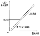
- FIG. 9 is a diagram showing an example in which light control is performed by controlling the light emission period of the LED or by the element shutter according to the exposure time.
- the control of the light emission period of the LED is performed by control of the continuous application time of the drive current supplied to each color LED within the maximum light emission period as shown in FIG. 2, that is, pulse width modulation (PWM) control.
- PWM pulse width modulation
- the control of the light emission period of the LED by pulse width modulation not only restricts the maximum light emission period but also restricts the minimum light emission period (TLmin shown in FIG. 9), and the LED emits light for a time shorter than the minimum light emission period TLmin. It is not appropriate to perform dimming.
- dimming is controlled by performing pulse width modulation.
- the LED light emission period is maintained at, for example, the minimum light emission period TLmin.
- the element shutter of the CCD 13 based on the control of the video processor 4
- exposure corresponding to the light emission amount in the light emission period shorter than the minimum light emission period TLmin is performed.
- the element shutter is known to be the exposure start point of the photodiode (for example, the point at which new charge starts to be accumulated in the photodiode because the charge is transferred from the photodiode to the vertical transfer path (CCD In the case of (1), or when the application of the reset voltage to the photodiode is completed, the time when new charge starts to be accumulated in the photodiode (in the case of CMOS)) is the time when the element shutter is opened, and the exposure to the photodiode is completed.
- CCD the exposure start point of the photodiode
- the time when new charge starts to be accumulated in the photodiode in the case of CMOS
- the element shutter closes at a point in time (for example, when charge is transferred from the photodiode to the vertical transfer path (in the case of CCD) or when charge is transferred from the photodiode to a memory such as a capacitor or floating diffusion (in the case of CMOS)). This is the control at the point in time.
- the start of exposure is performed by the start of LED light emission (that is, the start of application of drive current to the LED), and the end of exposure is performed by the timing of closing the element shutter. Conceivable.
- the video processor 4 can immediately shift to the reading period, and the frame rate can be easily improved.
- the present invention is not limited to this.
- the exposure is started at the timing when the element shutter is opened after the LED starts to emit light, and the exposure is completed at the timing when the element shutter is closed before the LED finishes emitting light. Is also possible.
- the drive current setting unit 35 and the video processor 4 of the light source device 3 perform, for example, the following control for each LED color.
- the drive current setting unit 35 receives the difference between the target brightness value and the current brightness value from the video processor 4, and when the received difference is within a range that can be handled by LED dimming, FIG. LED dimming indicated by the solid line is performed, and the LED dimming value is transmitted to the video processor 4. In this case, the video processor 4 does not need to perform light control using the element shutter.
- the difference between the target brightness value received from the video processor 4 and the current brightness value exceeds the range that can be handled by LED dimming (that is, the exposure time is the minimum light emission period). If it is less than TLmin), the LED light emission period is set to the minimum light emission period TLmin, and the LED dimming value is transmitted to the video processor 4.
- the video processor 4 determines whether or not the difference between the target brightness value and the current brightness value still exists. If it is determined that there is still a difference even during the minimum light emission period TLmin, the current brightness value is set to the target brightness by calculating a time corresponding to the difference and using the element shutter together. Control to match the value.
- the effects similar to those of the first and second embodiments described above can be obtained, and the element shutter of the image sensor can be controlled with a high time resolution, so that it is shorter than the minimum light emission period TLmin.
- the element shutter of the image sensor can be controlled with a high time resolution, so that it is shorter than the minimum light emission period TLmin.
- the light source device 3 receives the difference between the target brightness value and the current brightness value from the video processor 4, it is not necessary to perform comparison or the like, and the LED adjustment is performed according to the received difference value. Since the amount of light only needs to be controlled, it is possible to improve the response.
- the endoscope system including the light source device has been mainly described.
- an operation method for operating the endoscope system including the light source device as described above may be used, or an endoscope in which the computer includes the light source device. It may be a control program for controlling the mirror system as described above, a non-temporary recording medium readable by a computer for recording the control program, or the like.
- the present invention is not limited to the above-described embodiment as it is, and can be embodied by modifying the constituent elements without departing from the scope of the invention in the implementation stage.
- various aspects of the invention can be formed by appropriately combining a plurality of components disclosed in the embodiment. For example, you may delete some components from all the components shown by embodiment.
- the constituent elements over different embodiments may be appropriately combined.
Landscapes
- Health & Medical Sciences (AREA)
- Life Sciences & Earth Sciences (AREA)
- Surgery (AREA)
- Physics & Mathematics (AREA)
- Engineering & Computer Science (AREA)
- Optics & Photonics (AREA)
- Heart & Thoracic Surgery (AREA)
- Animal Behavior & Ethology (AREA)
- Pathology (AREA)
- Radiology & Medical Imaging (AREA)
- Biophysics (AREA)
- Biomedical Technology (AREA)
- Veterinary Medicine (AREA)
- Medical Informatics (AREA)
- Molecular Biology (AREA)
- Nuclear Medicine, Radiotherapy & Molecular Imaging (AREA)
- General Health & Medical Sciences (AREA)
- Public Health (AREA)
- Signal Processing (AREA)
- Microelectronics & Electronic Packaging (AREA)
- Astronomy & Astrophysics (AREA)
- General Physics & Mathematics (AREA)
- Endoscopes (AREA)
- Instruments For Viewing The Inside Of Hollow Bodies (AREA)
Abstract
Priority Applications (4)
| Application Number | Priority Date | Filing Date | Title |
|---|---|---|---|
| CN201480030326.7A CN105407789B (zh) | 2013-08-01 | 2014-07-28 | 内窥镜系统、内窥镜系统的工作方法 |
| JP2015506436A JP5802860B2 (ja) | 2013-08-01 | 2014-07-28 | 内視鏡システム |
| EP14831416.4A EP3011892A4 (fr) | 2013-08-01 | 2014-07-28 | Système d'endoscope et procédé d'utilisation d'un système endoscopique |
| US15/011,882 US9826894B2 (en) | 2013-08-01 | 2016-02-01 | Endoscope system with frame-sequential light emission |
Applications Claiming Priority (2)
| Application Number | Priority Date | Filing Date | Title |
|---|---|---|---|
| JP2013160749 | 2013-08-01 | ||
| JP2013-160749 | 2013-08-01 |
Related Child Applications (1)
| Application Number | Title | Priority Date | Filing Date |
|---|---|---|---|
| US15/011,882 Continuation US9826894B2 (en) | 2013-08-01 | 2016-02-01 | Endoscope system with frame-sequential light emission |
Publications (1)
| Publication Number | Publication Date |
|---|---|
| WO2015016172A1 true WO2015016172A1 (fr) | 2015-02-05 |
Family
ID=52431705
Family Applications (1)
| Application Number | Title | Priority Date | Filing Date |
|---|---|---|---|
| PCT/JP2014/069806 Ceased WO2015016172A1 (fr) | 2013-08-01 | 2014-07-28 | Système d'endoscope et procédé d'utilisation d'un système endoscopique |
Country Status (5)
| Country | Link |
|---|---|
| US (1) | US9826894B2 (fr) |
| EP (1) | EP3011892A4 (fr) |
| JP (1) | JP5802860B2 (fr) |
| CN (1) | CN105407789B (fr) |
| WO (1) | WO2015016172A1 (fr) |
Cited By (25)
| Publication number | Priority date | Publication date | Assignee | Title |
|---|---|---|---|---|
| WO2016185763A1 (fr) * | 2015-05-15 | 2016-11-24 | ソニー株式会社 | Dispositif de commande de source de lumière, procédé de commande de source de lumière, et système d'imagerie |
| JP2016209517A (ja) * | 2015-05-12 | 2016-12-15 | 富士フイルム株式会社 | 内視鏡システム及びその作動方法 |
| JP2017012637A (ja) * | 2015-07-06 | 2017-01-19 | 富士フイルム株式会社 | 内視鏡システム及びその作動方法 |
| WO2018003241A1 (fr) * | 2016-06-27 | 2018-01-04 | ソニー株式会社 | Dispositif d'éclairage, procédé de commande pour dispositif d'éclairage et système d'imagerie |
| CN107635452A (zh) * | 2015-06-02 | 2018-01-26 | 奥林巴斯株式会社 | 特殊光内窥镜装置 |
| JP2018033719A (ja) * | 2016-08-31 | 2018-03-08 | 富士フイルム株式会社 | 内視鏡システム及び内視鏡システムの作動方法 |
| JP2019080624A (ja) * | 2017-10-27 | 2019-05-30 | ソニー・オリンパスメディカルソリューションズ株式会社 | 医療用光源装置及び医療用内視鏡装置 |
| JP2020151090A (ja) * | 2019-03-19 | 2020-09-24 | ソニー・オリンパスメディカルソリューションズ株式会社 | 医療用光源装置及び医療用観察システム |
| JP2021508547A (ja) * | 2017-12-27 | 2021-03-11 | エシコン エルエルシーEthicon LLC | 光不足環境における蛍光撮像 |
| US11391426B2 (en) | 2018-12-04 | 2022-07-19 | Olympus Corporation | Light source device and light-amount adjusting method |
| US11924535B2 (en) | 2019-06-20 | 2024-03-05 | Cila GmbH International | Controlling integral energy of a laser pulse in a laser mapping imaging system |
| US11974860B2 (en) | 2019-06-20 | 2024-05-07 | Cilag Gmbh International | Offset illumination of a scene using multiple emitters in a hyperspectral, fluorescence, and laser mapping imaging system |
| US12007550B2 (en) | 2019-06-20 | 2024-06-11 | Cilag Gmbh International | Driving light emissions according to a jitter specification in a spectral imaging system |
| US12013496B2 (en) | 2019-06-20 | 2024-06-18 | Cilag Gmbh International | Noise aware edge enhancement in a pulsed laser mapping imaging system |
| US12025559B2 (en) | 2019-06-20 | 2024-07-02 | Cilag Gmbh International | Minimizing image sensor input/output in a pulsed laser mapping imaging system |
| US12058431B2 (en) | 2019-06-20 | 2024-08-06 | Cilag Gmbh International | Hyperspectral imaging in a light deficient environment |
| US12064211B2 (en) | 2019-06-20 | 2024-08-20 | Cilag Gmbh International | Noise aware edge enhancement in a pulsed hyperspectral, fluorescence, and laser mapping imaging system |
| US12126887B2 (en) | 2019-06-20 | 2024-10-22 | Cilag Gmbh International | Hyperspectral and fluorescence imaging with topology laser scanning in a light deficient environment |
| US12133715B2 (en) | 2019-06-20 | 2024-11-05 | Cilag Gmbh International | Hyperspectral and fluorescence imaging and topology laser mapping with minimal area monolithic image sensor |
| US12148130B2 (en) | 2019-06-20 | 2024-11-19 | Cilag Gmbh International | Super resolution and color motion artifact correction in a pulsed hyperspectral, fluorescence, and laser mapping imaging system |
| US12228516B2 (en) | 2019-06-20 | 2025-02-18 | Cilag Gmbh International | Image synchronization without input clock and data transmission clock in a pulsed hyperspectral, fluorescence, and laser mapping imaging system |
| US12306306B2 (en) | 2019-06-20 | 2025-05-20 | Cilag Gmbh International | Hyperspectral, fluorescence, and laser mapping imaging with fixed pattern noise cancellation |
| US12357162B2 (en) | 2019-06-20 | 2025-07-15 | Cilag Gmbh International | Videostroboscopy of vocal cords with a hyperspectral, fluorescence, and laser mapping imaging system |
| US12440085B2 (en) | 2019-06-20 | 2025-10-14 | Cilag Gmbh International | Image synchronization without input clock and data transmission clock in a pulsed laser mapping imaging system |
| US12514504B2 (en) | 2019-06-20 | 2026-01-06 | Cilag Gmbh International | Optical fiber waveguide in an endoscopic system for hyperspectral, fluorescence, and laser mapping imaging |
Families Citing this family (24)
| Publication number | Priority date | Publication date | Assignee | Title |
|---|---|---|---|---|
| EP2992810B1 (fr) * | 2012-07-26 | 2021-11-10 | DePuy Synthes Products, Inc. | Vidéo en continu dans un environnement peu éclairé |
| WO2015143453A1 (fr) | 2014-03-21 | 2015-09-24 | Olive Medical Corporation | Connecteur latéral de carte pour un capteur d'imagerie |
| JP6355527B2 (ja) * | 2014-10-31 | 2018-07-11 | 富士フイルム株式会社 | 内視鏡システム及びその作動方法 |
| JP6072369B2 (ja) * | 2015-02-04 | 2017-02-01 | オリンパス株式会社 | 内視鏡装置 |
| CN109715041B (zh) * | 2016-10-25 | 2021-08-10 | 深圳迈瑞生物医疗电子股份有限公司 | 医用光源装置 |
| EP3417758A1 (fr) | 2017-06-19 | 2018-12-26 | Ambu A/S | Un procédé de traitement de données d'image à le aide d'un modèle de mise à le échelle non linéaire et un système de prothèse visuelle médical |
| JP6834842B2 (ja) * | 2017-08-10 | 2021-02-24 | オムロン株式会社 | 設定支援装置、画像処理システムおよび設定支援プログラム |
| CN111050629B (zh) * | 2017-08-23 | 2022-09-06 | 富士胶片株式会社 | 内窥镜系统 |
| JP6924837B2 (ja) | 2017-09-22 | 2021-08-25 | 富士フイルム株式会社 | 医療画像処理システム、内視鏡システム、診断支援装置、並びに医療業務支援装置 |
| US11147441B2 (en) | 2018-01-16 | 2021-10-19 | Welch Allyn, Inc. | Physical assessment device |
| CN108371535A (zh) * | 2018-01-26 | 2018-08-07 | 重庆金山医疗器械有限公司 | 内窥镜多色照明系统 |
| JP6947918B2 (ja) * | 2018-04-05 | 2021-10-13 | オリンパス株式会社 | 内視鏡用光源装置及びその発光光量制御方法 |
| JP2019185002A (ja) * | 2018-04-11 | 2019-10-24 | ソニー株式会社 | 顕微鏡システム及び医療用光源装置 |
| CN112118778B (zh) * | 2018-05-21 | 2024-10-25 | 奥林巴斯株式会社 | 内窥镜系统、内窥镜用处理器、内窥镜系统的控制方法和记录介质 |
| US10638921B2 (en) * | 2018-07-20 | 2020-05-05 | Arthrex, Inc. | Medical imaging system |
| JP2022036326A (ja) * | 2018-08-29 | 2022-03-08 | オリンパス株式会社 | 内視鏡システム |
| JP6916768B2 (ja) * | 2018-09-05 | 2021-08-11 | 富士フイルム株式会社 | 内視鏡システム |
| JP7191978B2 (ja) * | 2018-11-12 | 2022-12-19 | オリンパス株式会社 | 内視鏡用光源装置、内視鏡装置及び光量調整方法 |
| GB2579801B (en) * | 2018-12-13 | 2021-04-14 | Exalos Ag | Superluminescent diode module |
| GB2580956B (en) | 2019-01-31 | 2023-01-25 | Exalos Ag | Amplified Spontaneous Emission Semiconductor Source |
| JP7374598B2 (ja) * | 2019-03-15 | 2023-11-07 | ソニー・オリンパスメディカルソリューションズ株式会社 | 光源装置、医療用観察システム、照明方法およびプログラム |
| JP7239360B2 (ja) * | 2019-03-19 | 2023-03-14 | ソニー・オリンパスメディカルソリューションズ株式会社 | 光源装置、医療用観察システム、照明方法およびプログラム |
| CN111343389B (zh) * | 2019-05-16 | 2021-09-10 | 杭州海康慧影科技有限公司 | 一种自动曝光控制方法及装置 |
| CN115802538A (zh) * | 2022-11-09 | 2023-03-14 | 昆山多宾陈列展示股份有限公司 | 一种灯光颜色控制方法、系统、终端及存储介质 |
Citations (4)
| Publication number | Priority date | Publication date | Assignee | Title |
|---|---|---|---|---|
| JP2006280465A (ja) * | 2005-03-31 | 2006-10-19 | Olympus Medical Systems Corp | 光源装置及び撮像装置 |
| JP2010158415A (ja) | 2009-01-08 | 2010-07-22 | Hoya Corp | 内視鏡用光源装置 |
| JP2011036361A (ja) | 2009-08-10 | 2011-02-24 | Fujifilm Corp | 内視鏡装置 |
| JP2012035090A (ja) * | 2011-09-20 | 2012-02-23 | Toshiba Corp | 電子内視鏡装置 |
Family Cites Families (10)
| Publication number | Priority date | Publication date | Assignee | Title |
|---|---|---|---|---|
| US6464633B1 (en) * | 1999-08-23 | 2002-10-15 | Olympus Optical Co., Ltd. | Light source device for endoscope using DMD |
| JP2003093336A (ja) | 2001-09-26 | 2003-04-02 | Toshiba Corp | 電子内視鏡装置 |
| JP2003135393A (ja) * | 2001-10-30 | 2003-05-13 | Olympus Optical Co Ltd | 内視鏡システムの自動調整方法 |
| KR100961591B1 (ko) * | 2004-08-30 | 2010-06-04 | 올림푸스 가부시키가이샤 | 내시경 장치 |
| JP4868976B2 (ja) * | 2006-08-18 | 2012-02-01 | オリンパスメディカルシステムズ株式会社 | 内視鏡装置 |
| JP5767775B2 (ja) * | 2009-07-06 | 2015-08-19 | 富士フイルム株式会社 | 内視鏡装置 |
| WO2011079148A1 (fr) * | 2009-12-22 | 2011-06-30 | Integrated Endoscopy, Inc. | Systèmes et procédés d'imagerie endoscopique avec détecteur monochromatique |
| JP5292379B2 (ja) * | 2010-11-09 | 2013-09-18 | 富士フイルム株式会社 | 内視鏡装置 |
| WO2012081336A1 (fr) * | 2010-12-13 | 2012-06-21 | オリンパスメディカルシステムズ株式会社 | Appareil médical |
| JP6270465B2 (ja) * | 2013-12-25 | 2018-01-31 | オリンパス株式会社 | 光走査型観察装置 |
-
2014
- 2014-07-28 WO PCT/JP2014/069806 patent/WO2015016172A1/fr not_active Ceased
- 2014-07-28 EP EP14831416.4A patent/EP3011892A4/fr not_active Withdrawn
- 2014-07-28 JP JP2015506436A patent/JP5802860B2/ja active Active
- 2014-07-28 CN CN201480030326.7A patent/CN105407789B/zh active Active
-
2016
- 2016-02-01 US US15/011,882 patent/US9826894B2/en active Active
Patent Citations (4)
| Publication number | Priority date | Publication date | Assignee | Title |
|---|---|---|---|---|
| JP2006280465A (ja) * | 2005-03-31 | 2006-10-19 | Olympus Medical Systems Corp | 光源装置及び撮像装置 |
| JP2010158415A (ja) | 2009-01-08 | 2010-07-22 | Hoya Corp | 内視鏡用光源装置 |
| JP2011036361A (ja) | 2009-08-10 | 2011-02-24 | Fujifilm Corp | 内視鏡装置 |
| JP2012035090A (ja) * | 2011-09-20 | 2012-02-23 | Toshiba Corp | 電子内視鏡装置 |
Non-Patent Citations (1)
| Title |
|---|
| See also references of EP3011892A4 |
Cited By (39)
| Publication number | Priority date | Publication date | Assignee | Title |
|---|---|---|---|---|
| JP2016209517A (ja) * | 2015-05-12 | 2016-12-15 | 富士フイルム株式会社 | 内視鏡システム及びその作動方法 |
| WO2016185763A1 (fr) * | 2015-05-15 | 2016-11-24 | ソニー株式会社 | Dispositif de commande de source de lumière, procédé de commande de source de lumière, et système d'imagerie |
| US10397489B2 (en) | 2015-05-15 | 2019-08-27 | Sony Corporation | Light source control device, method of controlling light source, and image capture system |
| JPWO2016185763A1 (ja) * | 2015-05-15 | 2018-03-01 | ソニー株式会社 | 光源制御装置及び光源制御方法並びに撮像システム |
| CN107635452A (zh) * | 2015-06-02 | 2018-01-26 | 奥林巴斯株式会社 | 特殊光内窥镜装置 |
| CN107635452B (zh) * | 2015-06-02 | 2019-09-13 | 奥林巴斯株式会社 | 特殊光内窥镜装置 |
| JP2017012637A (ja) * | 2015-07-06 | 2017-01-19 | 富士フイルム株式会社 | 内視鏡システム及びその作動方法 |
| WO2018003241A1 (fr) * | 2016-06-27 | 2018-01-04 | ソニー株式会社 | Dispositif d'éclairage, procédé de commande pour dispositif d'éclairage et système d'imagerie |
| JP2018033719A (ja) * | 2016-08-31 | 2018-03-08 | 富士フイルム株式会社 | 内視鏡システム及び内視鏡システムの作動方法 |
| US10856730B2 (en) | 2017-10-27 | 2020-12-08 | Sony Olympus Medical Solutions Inc. | Medical light source device and medical endoscopic device |
| JP2019080624A (ja) * | 2017-10-27 | 2019-05-30 | ソニー・オリンパスメディカルソリューションズ株式会社 | 医療用光源装置及び医療用内視鏡装置 |
| US12020450B2 (en) | 2017-12-27 | 2024-06-25 | Cilag Gmbh International | Fluorescence imaging in a light deficient environment |
| JP2021508547A (ja) * | 2017-12-27 | 2021-03-11 | エシコン エルエルシーEthicon LLC | 光不足環境における蛍光撮像 |
| JP2021508543A (ja) * | 2017-12-27 | 2021-03-11 | エシコン エルエルシーEthicon LLC | 光不足環境におけるハイパースペクトル撮像 |
| US12026900B2 (en) | 2017-12-27 | 2024-07-02 | Cllag GmbH International | Hyperspectral imaging in a light deficient environment |
| US12518410B2 (en) | 2017-12-27 | 2026-01-06 | Cliag GmbH International | Hyperspectral imaging with tool tracking in a light deficient environment |
| US12499566B2 (en) | 2017-12-27 | 2025-12-16 | Cilag Gmbh International | Hyperspectral imaging in a light deficient environment |
| US11391426B2 (en) | 2018-12-04 | 2022-07-19 | Olympus Corporation | Light source device and light-amount adjusting method |
| JP2020151090A (ja) * | 2019-03-19 | 2020-09-24 | ソニー・オリンパスメディカルソリューションズ株式会社 | 医療用光源装置及び医療用観察システム |
| JP7224985B2 (ja) | 2019-03-19 | 2023-02-20 | ソニー・オリンパスメディカルソリューションズ株式会社 | 医療用光源装置及び医療用観察システム |
| US11974860B2 (en) | 2019-06-20 | 2024-05-07 | Cilag Gmbh International | Offset illumination of a scene using multiple emitters in a hyperspectral, fluorescence, and laser mapping imaging system |
| US12013496B2 (en) | 2019-06-20 | 2024-06-18 | Cilag Gmbh International | Noise aware edge enhancement in a pulsed laser mapping imaging system |
| US12007550B2 (en) | 2019-06-20 | 2024-06-11 | Cilag Gmbh International | Driving light emissions according to a jitter specification in a spectral imaging system |
| US12025559B2 (en) | 2019-06-20 | 2024-07-02 | Cilag Gmbh International | Minimizing image sensor input/output in a pulsed laser mapping imaging system |
| US12058431B2 (en) | 2019-06-20 | 2024-08-06 | Cilag Gmbh International | Hyperspectral imaging in a light deficient environment |
| US12064211B2 (en) | 2019-06-20 | 2024-08-20 | Cilag Gmbh International | Noise aware edge enhancement in a pulsed hyperspectral, fluorescence, and laser mapping imaging system |
| US12126887B2 (en) | 2019-06-20 | 2024-10-22 | Cilag Gmbh International | Hyperspectral and fluorescence imaging with topology laser scanning in a light deficient environment |
| US12133715B2 (en) | 2019-06-20 | 2024-11-05 | Cilag Gmbh International | Hyperspectral and fluorescence imaging and topology laser mapping with minimal area monolithic image sensor |
| US12148130B2 (en) | 2019-06-20 | 2024-11-19 | Cilag Gmbh International | Super resolution and color motion artifact correction in a pulsed hyperspectral, fluorescence, and laser mapping imaging system |
| US12181412B2 (en) | 2019-06-20 | 2024-12-31 | Cilag Gmbh International | Minimizing image sensor input/output in a pulsed hyperspectral, fluorescence, and laser mapping imaging system |
| US12228516B2 (en) | 2019-06-20 | 2025-02-18 | Cilag Gmbh International | Image synchronization without input clock and data transmission clock in a pulsed hyperspectral, fluorescence, and laser mapping imaging system |
| US12267573B2 (en) | 2019-06-20 | 2025-04-01 | Cilag Gmbh International | Controlling integral energy of a laser pulse in a hyperspectral, fluorescence, and laser mapping imaging system |
| US12306306B2 (en) | 2019-06-20 | 2025-05-20 | Cilag Gmbh International | Hyperspectral, fluorescence, and laser mapping imaging with fixed pattern noise cancellation |
| US12357162B2 (en) | 2019-06-20 | 2025-07-15 | Cilag Gmbh International | Videostroboscopy of vocal cords with a hyperspectral, fluorescence, and laser mapping imaging system |
| US12440085B2 (en) | 2019-06-20 | 2025-10-14 | Cilag Gmbh International | Image synchronization without input clock and data transmission clock in a pulsed laser mapping imaging system |
| US12458290B2 (en) | 2019-06-20 | 2025-11-04 | Cilag Gmbh International | Offset illumination of a scene using multiple emitters in a hyperspectral, fluorescence, and laser mapping imaging system |
| US11949974B2 (en) | 2019-06-20 | 2024-04-02 | Cilag Gmbh International | Controlling integral energy of a laser pulse in a fluorescence imaging system |
| US11924535B2 (en) | 2019-06-20 | 2024-03-05 | Cila GmbH International | Controlling integral energy of a laser pulse in a laser mapping imaging system |
| US12514504B2 (en) | 2019-06-20 | 2026-01-06 | Cilag Gmbh International | Optical fiber waveguide in an endoscopic system for hyperspectral, fluorescence, and laser mapping imaging |
Also Published As
| Publication number | Publication date |
|---|---|
| CN105407789B (zh) | 2017-07-14 |
| US20160143520A1 (en) | 2016-05-26 |
| US9826894B2 (en) | 2017-11-28 |
| EP3011892A4 (fr) | 2017-04-26 |
| EP3011892A1 (fr) | 2016-04-27 |
| JPWO2015016172A1 (ja) | 2017-03-02 |
| CN105407789A (zh) | 2016-03-16 |
| JP5802860B2 (ja) | 2015-11-04 |
Similar Documents
| Publication | Publication Date | Title |
|---|---|---|
| JP5802860B2 (ja) | 内視鏡システム | |
| JP6138203B2 (ja) | 内視鏡装置 | |
| EP2679137B1 (fr) | Appareil de type endoscope pour le réglage de la quantité de lumière de l'imagerie par fluorescence | |
| JP5379932B1 (ja) | 撮像システム、撮像方法 | |
| JP5452785B1 (ja) | 撮像システム | |
| JP6072369B2 (ja) | 内視鏡装置 | |
| WO2014028758A1 (fr) | Système et procédé d'éclairage de caméra endoscopique | |
| JP5659315B2 (ja) | 内視鏡装置 | |
| JP5989284B1 (ja) | 撮像システム及び光源装置 | |
| JP6150944B2 (ja) | 撮像システム | |
| JP6762816B2 (ja) | 内視鏡システム及びその作動方法 | |
| JP2010158413A (ja) | 内視鏡用光源装置 | |
| JP2012223376A (ja) | 照明用発光ダイオードの制御回路、制御方法及びそれを用いた電子内視鏡装置 | |
| JP6982677B2 (ja) | 被検体観察システム、内視鏡用光源装置、被検体観察システムの作動方法、被検体観察システムの作動プログラム | |
| JP5974187B2 (ja) | 撮像システム | |
| JP2013020171A (ja) | 発光装置及びこれを備えた撮像装置、並びに調光方法 |
Legal Events
| Date | Code | Title | Description |
|---|---|---|---|
| WWE | Wipo information: entry into national phase |
Ref document number: 201480030326.7 Country of ref document: CN |
|
| ENP | Entry into the national phase |
Ref document number: 2015506436 Country of ref document: JP Kind code of ref document: A |
|
| 121 | Ep: the epo has been informed by wipo that ep was designated in this application |
Ref document number: 14831416 Country of ref document: EP Kind code of ref document: A1 |
|
| WWE | Wipo information: entry into national phase |
Ref document number: 2014831416 Country of ref document: EP |
|
| NENP | Non-entry into the national phase |
Ref country code: DE |