WO2015016199A1 - 炭素繊維束および耐炎化繊維束 - Google Patents
炭素繊維束および耐炎化繊維束 Download PDFInfo
- Publication number
- WO2015016199A1 WO2015016199A1 PCT/JP2014/069890 JP2014069890W WO2015016199A1 WO 2015016199 A1 WO2015016199 A1 WO 2015016199A1 JP 2014069890 W JP2014069890 W JP 2014069890W WO 2015016199 A1 WO2015016199 A1 WO 2015016199A1
- Authority
- WO
- WIPO (PCT)
- Prior art keywords
- fiber bundle
- carbon fiber
- cross
- major axis
- points
- Prior art date
- Legal status (The legal status is an assumption and is not a legal conclusion. Google has not performed a legal analysis and makes no representation as to the accuracy of the status listed.)
- Ceased
Links
Images




Classifications
-
- D—TEXTILES; PAPER
- D01—NATURAL OR MAN-MADE THREADS OR FIBRES; SPINNING
- D01F—CHEMICAL FEATURES IN THE MANUFACTURE OF ARTIFICIAL FILAMENTS, THREADS, FIBRES, BRISTLES OR RIBBONS; APPARATUS SPECIALLY ADAPTED FOR THE MANUFACTURE OF CARBON FILAMENTS
- D01F9/00—Artificial filaments or the like of other substances; Manufacture thereof; Apparatus specially adapted for the manufacture of carbon filaments
- D01F9/08—Artificial filaments or the like of other substances; Manufacture thereof; Apparatus specially adapted for the manufacture of carbon filaments of inorganic material
- D01F9/12—Carbon filaments; Apparatus specially adapted for the manufacture thereof
-
- D—TEXTILES; PAPER
- D01—NATURAL OR MAN-MADE THREADS OR FIBRES; SPINNING
- D01D—MECHANICAL METHODS OR APPARATUS IN THE MANUFACTURE OF ARTIFICIAL FILAMENTS, THREADS, FIBRES, BRISTLES OR RIBBONS
- D01D5/00—Formation of filaments, threads, or the like
- D01D5/253—Formation of filaments, threads, or the like with a non-circular cross section; Spinnerette packs therefor
-
- C—CHEMISTRY; METALLURGY
- C01—INORGANIC CHEMISTRY
- C01B—NON-METALLIC ELEMENTS; COMPOUNDS THEREOF; METALLOIDS OR COMPOUNDS THEREOF NOT COVERED BY SUBCLASS C01C
- C01B32/00—Carbon; Compounds thereof
-
- D—TEXTILES; PAPER
- D01—NATURAL OR MAN-MADE THREADS OR FIBRES; SPINNING
- D01F—CHEMICAL FEATURES IN THE MANUFACTURE OF ARTIFICIAL FILAMENTS, THREADS, FIBRES, BRISTLES OR RIBBONS; APPARATUS SPECIALLY ADAPTED FOR THE MANUFACTURE OF CARBON FILAMENTS
- D01F9/00—Artificial filaments or the like of other substances; Manufacture thereof; Apparatus specially adapted for the manufacture of carbon filaments
- D01F9/08—Artificial filaments or the like of other substances; Manufacture thereof; Apparatus specially adapted for the manufacture of carbon filaments of inorganic material
- D01F9/12—Carbon filaments; Apparatus specially adapted for the manufacture thereof
- D01F9/14—Carbon filaments; Apparatus specially adapted for the manufacture thereof by decomposition of organic filaments
-
- D—TEXTILES; PAPER
- D01—NATURAL OR MAN-MADE THREADS OR FIBRES; SPINNING
- D01F—CHEMICAL FEATURES IN THE MANUFACTURE OF ARTIFICIAL FILAMENTS, THREADS, FIBRES, BRISTLES OR RIBBONS; APPARATUS SPECIALLY ADAPTED FOR THE MANUFACTURE OF CARBON FILAMENTS
- D01F6/00—Monocomponent artificial filaments or the like of synthetic polymers; Manufacture thereof
- D01F6/02—Monocomponent artificial filaments or the like of synthetic polymers; Manufacture thereof from homopolymers obtained by reactions only involving carbon-to-carbon unsaturated bonds
- D01F6/20—Monocomponent artificial filaments or the like of synthetic polymers; Manufacture thereof from homopolymers obtained by reactions only involving carbon-to-carbon unsaturated bonds from polymers of cyclic compounds with one carbon-to-carbon double bond in the side chain
- D01F6/22—Monocomponent artificial filaments or the like of synthetic polymers; Manufacture thereof from homopolymers obtained by reactions only involving carbon-to-carbon unsaturated bonds from polymers of cyclic compounds with one carbon-to-carbon double bond in the side chain from polystyrene
Definitions
- the present invention relates to a carbon fiber bundle that contains a single fiber having a specific cross-sectional shape as a main component and is convenient for analyzing the cause of breakage, and a flame-resistant fiber bundle suitable for obtaining the same.
- Carbon fiber composite materials are widely used in sports and aircraft applications because of their excellent specific strength and specific elastic modulus. In recent years, efforts toward application to automobiles have been accelerated worldwide. Carbon fiber composite materials have the greatest feature that they can reduce the weight of applied components while maintaining equivalent mechanical properties compared to conventional materials centered on metals. The price is still relatively high, reflecting the price of the carbon fiber that is the raw material, so it has not completely replaced the conventional material. It is often pointed out that the manufacturing process is complicated and complicated because of the relatively high price of carbon fiber. The manufacturing process is complicated and complicated, which increases equipment costs and utility costs.In addition, when a defect occurs in the manufactured carbon fiber, it is difficult to identify the process that causes it, Since the solution tends to take time, the facility operation rate is lowered. The effects of these combined actions on the production cost of carbon fiber cannot be ignored when setting the price of carbon fiber.
- strand strength When the tensile strength of the resin-impregnated strand of the produced carbon fiber (hereinafter sometimes simply referred to as “strand strength”) is lowered, it is often investigated one by one whether there is no abnormality in each process of production. Specifically, it is often the case that a management record of each of these steps is first traced to confirm that there is no abnormality, and a forced deterioration test is performed for the purpose of factor separation. Such a cause investigation process often takes labor and time. Moreover, the carbon fiber itself may be analyzed. A single fiber tensile test is often performed, and the cause of the strength reduction is often examined from the observation of the strength distribution and the fracture surface of the collected test piece.
- Carbon fiber which is a brittle material, is known to start breaking from stress-concentrated defects such as foreign objects, scratches, and dents, leaving a characteristic trace on the fracture surface, and a trace left on the fracture surface
- the position of the break start point can be identified from the above. That is, when the fractured test piece is collected and the fracture surface of the single fiber of carbon fiber is observed, a line extending radially from a certain point can be confirmed, and the starting point of the line extending radially is the break starting point.
- the break start point and the defects that cause it are often present on the outer periphery of the single fiber.
- the reasons for this are not completely clear at the moment, but include bonding between single fibers in the yarn-making process, rubbing with rollers, contact with adhesion and dust in the firing process, and electrolytic treatment in the surface treatment process.
- cross-sectional shape when the shape of the cross section perpendicular to the fiber direction of the single fiber (hereinafter sometimes simply referred to as “cross-sectional shape”) is not circular, the relative position of the fracture start point with respect to the non-circular cross-sectional shape (for example, elliptical shape) If this is the case, it is possible to check the relative short axis from the intersection of the major axis and the outer circumference. It is possible to obtain information as to whether or not it is localized at a specific position.
- the cross-sectional shape is an empty bean shape as an example, it is estimated that there are few opportunities for rubbing and contact in the recessed part, but in the process of contact with liquid such as electrolytic treatment, it is affected in the same way as other parts Therefore, by observing the fracture surface and investigating whether the fracture start point is concentrated in the hollow bean-shaped indentations, or whether it is distributed as a whole, it can be scratched or contacted between single fibers or with a roller, Or it can be expected that any of the contact with the fluid such as electrolytic treatment is doubtful or separated.
- Patent Document 4 discloses that convergence and spreadability can be achieved at a high level by using an acrylic fiber bundle in which empty beans, ellipses, and circular single fibers are mixed at a specific ratio.
- a complex base having a hollow bean shape, an elliptical shape, and a circular hole is essential, and in order to stably produce single fibers having greatly different cross-sectional shapes, conditions are set according to the cross-sectional shape having the lowest processability. It was difficult to apply to industrial processes.
- JP-A-3-97918 JP-A-4-202815 Japanese Patent Laid-Open No. 11-302916 JP 2012-188766 A
- An object of the present invention is to provide a carbon fiber bundle and a flame-resistant fiber bundle containing as a main component a single fiber having an oval cross-sectional shape.
- the present inventors have found that the shape of the cross section perpendicular to the fiber direction is substantially oval and contains 40% or more of single fibers simultaneously satisfying the following formulas (1) and (2):
- the present inventors have found that a fiber bundle is effective in solving the above-described problems, and have reached the present invention. 1.03 ⁇ La / Lb ⁇ 1.20 (1) 1.05 ⁇ Ld / Lc ⁇ 1.25 (2) (However, the longest line segment passes through the two most distant points on the outer periphery of the monofilament substantially oval cross-section, and the short line is the line segment that passes through the midpoint of the long axis and the two points on the outer periphery and is orthogonal to the long axis.
- the major axis length is La and the minor axis length is Lb.
- Lc and Ld are the lengths of the two line segments orthogonal to the long axis.
- the carbon fiber bundle of the present invention and the carbon fiber bundle obtained from the flameproofed fiber bundle of the present invention have substantially the same oval cross-sectional shape as compared with the circular cross-section, the single fiber It is possible to evaluate the relative position of the fracture start point by observing the fracture surface. As a result, when an abnormality occurs in the tensile strength of the carbon fiber bundle, which is a product, the cause can be grasped effectively, and a reduction in manufacturing opportunity loss due to a reduction in equipment operation rate can be expected.
- FIG. 1 is an SEM observation image of a tensile fracture surface of a single fiber of carbon fiber.
- FIG. 2 is an example of base holes that can be suitably used in the present invention.
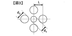
- FIG. 3 is an example of a cap hole that is not preferable for the present invention.
- FIG. 5 is an example of an SEM observation image of a tensile fracture surface of a single fiber of carbon fiber in Example 1.
- 6 is an example of an SEM observation image of a tensile fracture surface of a single fiber of carbon fiber in Example 2.
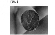
- FIG. FIG. 7 is an example of an SEM observation image of a tensile fracture surface of a single fiber of the flame resistant yarn in Example 1.
- the carbon fiber bundle of the present invention is a carbon fiber bundle that has a substantially oval cross-sectional shape perpendicular to the fiber direction and contains 40% or more of single fibers that simultaneously satisfy the following formulas (1) and (2). 1.03 ⁇ La / Lb ⁇ 1.20 (1) 1.05 ⁇ Ld / Lc ⁇ 1.25 (2)
- a long line is a line segment that passes through the two most distant points on the outer periphery of an approximately oval cross section of a single fiber
- a short line is a line segment that passes through the middle point of the long axis and two points on the outer periphery and is orthogonal to the long axis.
- the length of the major axis is La
- the length of the minor axis is Lb.
- the lengths of the two line segments that pass through the points other than the middle point of the major axis and the two points on the outer circumference and are orthogonal to the major axis are Lc, Ld, and To do.
- the cross section perpendicular to the fiber direction includes not only a cross section cut perpendicularly to the fiber length direction but also a tensile fracture surface. This is because carbon fiber, which is a brittle material, tends to have such an approximation because the tensile fracture surface tends to be almost perpendicular to the fiber direction.
- the shape of the cross section perpendicular to the fiber direction means that the cross section perpendicular to the fiber direction does not necessarily exist as a premise and can be recognized as an outer shape when the cross section is observed from the fiber direction. .
- the substantially oval shape refers to a deformed circle that is flat and asymmetric on both sides with respect to the short axis.
- the major axis refers to the line segment that passes through the two most distant points on the outer circumference
- the minor axis refers to the line segment that passes through the middle point of the major axis and two points on the outer circumference and is orthogonal to the major axis.
- Let the lengths be La and Lb, respectively. If the long axis cannot be determined very close to a perfect circle, an arbitrary line segment passing through the center of the circle and two points on the outer periphery is determined as the long axis.
- two points other than the intersection of the major axis and the minor axis pass through three points, each point and two points on the outer circumference.
- Two line segments perpendicular to the long axis can be drawn.
- the lengths of the line segments are Lc and Ld in order from the shortest one.
- the lower the symmetry the better the position distinction.
- an arbitrary point on the outer periphery is one point on the outer periphery that is folded with respect to the major axis, one point on the outer periphery that is folded with respect to the minor axis, and a shorter point after being folded with respect to the major axis. Indistinguishable from one point on the outer periphery which is also folded with respect to the axis. That is, there are four equivalent points.
- a substantially oval shape there may be a line symmetry with respect to the major axis, but there is no such limitation on the symmetry, and the symmetry of a circular or elliptical shape or a substantially oval shape is low.
- the cross-sectional shape is circular, it is not possible to obtain information useful for understanding the cause of the break, such as whether the relative position of the break start point is concentrated in a specific location or evenly distributed, but symmetry The lower the value, the smaller the number of points equivalent to any one point on the outer circumference, so that the relative position of the break start point can be classified, and it can be expected that it can be usefully used to isolate the breakage factor. .
- the relative position of the break start point is, for example, a substantially oval shape centering on the intersection of the major axis and the minor axis, where the break start point exists at the tip of the approximately oval shape with respect to the approximately oval cross-sectional shape. It refers to the relative position of the break start point with respect to the cross-sectional shape, such as existing at an angle of 45 degrees from the tip.
- the substantially oval tip refers to the end of the long axis on the side of the point that divides the long axis giving Lc into four equal parts with respect to the midpoint of the long axis.
- a circle and an ellipse include a substantially circular shape and a substantially elliptical shape, respectively, because the actual cross-sectional shape of a single fiber rarely follows the mathematically exact definition of a circle or an ellipse. .
- Formula (1) is the ratio of the lengths of the major axis La and the minor axis Lb, and is circular when La / Lb is 1, and becomes flatter as it becomes larger.
- Equation (2) represents a deviation from an ellipse, which is elliptical when Ld / Lc is 1. The larger the distance between the midpoint of the major axis and the center of gravity, the higher the asymmetry. .
- La / Lb is not circular if La / Lb is 1.03 or more, and determine the long axis. We were able to.
- the cross-sectional shape is an ellipse, but it can be seen that it is not possible to visually recognize which is the tip of an approximately oval shape.
- La / Lb and Ld / Lc are too large, the tensile strength of the single fiber is lowered, and thus the strand strength tends to be lowered as a whole, but La / Lb is 1.20 or less, Ld / L If Lc is 1.25 or less, the strand strength is not lowered or negligible even when compared with the circular case.
- the shape of the cross section can be controlled mainly by devising a die described later.
- the ratio of single fibers that simultaneously satisfy the above formulas (1) and (2) is It must be present above a certain value. If the ratio is low, the ratio of single fibers having a circular cross-sectional shape in which the relative position of the fracture start point cannot be classified may increase. If the content of the single fiber that simultaneously satisfies the expressions (1) and (2) is 40% or more, there is no decrease in the strand strength, and the relative position of the break start point on the substantially oval cross section can be evaluated efficiently. .
- Such a ratio can be controlled mainly by setting the coagulation bath concentration condition and changing the distance of the space through which the spinning solution is discharged after being discharged from the die in dry and wet spinning.
- the carbon fiber bundle has a substantially oval cross section perpendicular to the fiber direction and contains 40% or more of single fibers that simultaneously satisfy the following formulas (3) and (4). 1.04 ⁇ La / Lb ⁇ 1.17 (3) 1.05 ⁇ Ld / Lc ⁇ 1.20 (4)
- La / Lb is 1.04 or more, it is preferable to make it easier to determine that the shape is not circular.
- Ld / Lc is 1.20 or less, the strand strength further decreases. It is preferable because it becomes smaller.
- ⁇ La / Lb> and ⁇ Ld / Lc> are average values of La / Lb and Ld / Lc in each single fiber in the carbon fiber bundle.
- the average value is calculated by sampling 100 single fibers randomly from the carbon fiber bundle.
- the carbon fiber bundle is composed of 400 or less single fibers, 25% of the single fibers are sampled and used. Specific evaluation methods will be described in Examples.
- Formula (5) is about the average value of La / Lb in each single fiber in the carbon fiber bundle, ⁇ La / Lb>, and as ⁇ La / Lb> increases, the number of flat single fibers increases.
- Equation (6) is for the average value of Ld / Lc in each single fiber in the carbon fiber bundle, ⁇ Ld / Lc>, and the distance between the midpoint of the long axis and the center of gravity increases as ⁇ Ld / Lc> increases.
- the number of single fibers having high asymmetry increases. Even if the ratio of the single fibers that simultaneously satisfy the above formulas (1) and (2) is 40% or more, when the other single fibers have a hollow cross-section such as a hollow bean shape or a multileaf shape, their relative By including a single fiber having a low tensile strength, fluff and fluff may increase in the obtained carbon fiber bundle and the quality may be lowered. Therefore, it is preferable that ⁇ La / Lb> satisfies 1.20 or less and ⁇ Ld / Lc> satisfies 1.20 or less simultaneously.
- the cross-sectional parameters La, Lb, Lc, and Ld are evaluated by observing the cross section of the single fiber.
- a tensile fracture surface, a polished cross-section, and the like can be observed and evaluated with an optical microscope, a scanning electron microscope, a transmission electron microscope, or the like. Since these parameters require 0.2% of the length whose resolution is to be measured, if the minor axis is 5 ⁇ m, it is necessary to evaluate using an electron microscope.
- a specific evaluation method will be described in Examples.
- the single fiber is not subjected to measurement, and a new single fiber is randomly sampled and used. To do.
- the carbon fiber bundle of the present invention preferably has a single fiber surface area ratio of 1.00 to 1.10 measured by a method described later using an atomic force microscope, and preferably 1.00 to 1.06. It is more preferable that The surface area ratio is represented by the ratio between the actual surface area of the carbon fiber surface and the projected area, and indicates the degree of surface roughness. As the surface area ratio approaches 1, it means that the surface area is smoother and tends to be advantageous in improving the tensile strength of the carbon fiber.
- the lower limit of the surface area ratio is 1.00 in principle. If the surface area ratio is 1.10 or less, the decrease in strength due to variations in the surface wrinkle shape is small, so the range can be controlled within the range of 1.00 to 1.10. preferable.
- the above surface area ratio is controlled by the spinning method and the coagulation method, and there is a tendency for dry and wet spinning to have a smooth surface.
- the coagulation rate is slowed, for example, the solvent concentration in the coagulation bath is set high.
- the diameter of the single fiber is smaller, the mechanical properties, particularly the tensile strength tends to be improved, but the productivity may be lowered.
- the diameter of the single fiber is large, the productivity is improved.
- the fiber in each precursor single fiber in the precursor fiber bundle is mainly used in the flameproofing process. Due to the fact that oxygen hardly diffuses from the surface to the inside, a difference in structure between the inside and outside of the single fiber may occur, and the mechanical properties may deteriorate. Because of these trade-offs, it is preferable that the average diameter of the single carbon fiber is in the range of 4 to 7 ⁇ m.
- the average diameter of the single fibers is an equivalent area equivalent circle diameter calculated so that the cross-sectional shapes can be uniformly compared even if they are not circular. A specific method of obtaining will be described in Examples.
- the carbon fiber bundle of the present invention preferably has both a strand strength and a resin-impregnated strand tensile modulus (hereinafter also referred to as a strand modulus) of 5.0 GPa or more and 230 GPa or more, respectively.
- the strand strength is more preferably 5.8 GPa or more, and further preferably 6.2 GPa or more.
- the strand elastic modulus is more preferably 260 GPa or more, and further preferably 300 GPa or more.
- the carbon fiber bundle of the present invention has a cross-sectional shape perpendicular to the fiber direction and has a substantially oval shape, and fires a flame-resistant fiber bundle containing 70% or more of single fibers simultaneously satisfying the above formulas (1) and (2). It is preferable to manufacture. Therefore, such a flameproof fiber bundle is also one of the preferred embodiments of the present invention.
- Precursors used for the production of carbon fiber precursor fiber bundles include carbons including polyacrylonitrile polymers, cellulose polymers, isotropic pitches, anisotropic pitches, polyimide compounds, and polyamic acid compounds. Although it can select suitably from well-known precursors for fiber precursor fiber manufacture, it is preferable to use a polyacrylonitrile-type polymer as a precursor mainly from a viewpoint of physical-property expression.
- the polyacrylonitrile-based polymer means a polymer in which at least acrylonitrile is a main constituent of the polymer skeleton, and the main constituent usually has a constitution that occupies 90 to 100 mol% of the polymer skeleton. It refers to ingredients.
- the polyacrylonitrile-based polymer contains a copolymer component from the viewpoint of improving the yarn-making property and efficiently performing the flameproofing treatment.
- the production method of the polyacrylonitrile-based polymer can be selected from known polymerization methods.
- the spinning dope is composed of the above-described polyacrylonitrile-based polymer and soluble in polyacrylonitrile such as dimethyl sulfoxide, dimethylformamide and dimethylacetamide. Dissolved in an appropriate solvent.
- the concentration of the polyacrylonitrile polymer in the spinning dope is preferably 10 to 23% by mass from the viewpoint of controlling the shape of the carbon fiber cross section.
- the spinning process includes a spinning process in which a spinning solution is discharged from a spinneret by a dry-wet spinning method and spinning, a water washing process in which fibers obtained in the spinning process are washed in a water bath, and a fiber obtained in the water washing process.
- a water bath stretching step for stretching in a water bath and a drying heat treatment step for subjecting the fibers obtained in the water bath stretching step to a dry heat treatment, and if necessary, a steam stretching step for steam stretching of the fibers obtained in the dry heat treatment step. May be included.
- the coagulation bath contains a solvent such as dimethyl sulfoxide, dimethylformamide, and dimethylacetamide used as a solvent for the spinning dope and a so-called coagulation promoting component.
- a solvent such as dimethyl sulfoxide, dimethylformamide, and dimethylacetamide used as a solvent for the spinning dope
- a so-called coagulation promoting component As the coagulation accelerating component, a component that does not dissolve the polyacrylonitrile polymer and is compatible with the solvent used in the spinning solution can be used. Specifically, it is preferable to use water as a coagulation promoting component. The higher the solvent concentration in the coagulation bath, the slower the coagulation rate and the easier it is to have a substantially oval cross-sectional shape.
- a carbon fiber precursor fiber suitable for obtaining a carbon fiber having a substantially oval cross-sectional shape can be obtained by adjusting the shape of the die hole.
- the mouthpiece hole can also have an approximately oval shape that is the same as the cross-sectional shape of the target single fiber.
- the spouted polymer can easily be united while passing through the air gap.
- two or more holes close to each other in that a single fiber whose cross-sectional shape is controlled to be substantially oval can be obtained only by combining circular holes with relatively low processing costs.
- the shape of a preferable nozzle hole in the present invention can be optimized by trial and error by those skilled in the art.
- (A) and (B) in FIG. 2 are preferable.
- the shape of the base hole should not be interpreted as being limited to these.
- the two or more holes are collectively counted as one cap hole.
- the mouthpiece hole preferably has a cross-sectional area of 0.002 to 0.1 mm 2 in order to obtain a carbon fiber having a small single fiber fineness which is advantageous for the expression of mechanical properties.
- the cross-sectional shape is not constant, so that the hole pitch, the number of holes, the hole arrangement, so that the cross-sectional shape of the present invention and the proportion of single fibers having the shape.
- One skilled in the art can easily optimize.
- the distance of the space through which the spinning solution is discharged after being discharged from the die in the wet and wet spinning is changed.
- the distance increases, the ratio of the cross-sectional shape approaching a circle increases.
- Such a distance is preferably controlled to approximately several mm.
- the carbon fiber precursor fiber bundle it is preferable to perform water washing using a water washing bath having a plurality of stages of 20 to 90 ° C. in the water washing step.
- the draw ratio in the water bath drawing step is preferably 1.3 to 5 times, more preferably 2 to 4 times.
- an oil agent made of silicone or the like to the yarn for the purpose of preventing adhesion between single fibers.
- a silicone oil agent it is preferable to use a modified silicone, and it is preferable to use one containing an amino-modified silicone having high heat resistance.
- the drying temperature is 70 to 200 ° C.
- Carbon suitable for obtaining the carbon fiber bundle of the present invention by performing steam stretching as necessary after the water washing step, water bath stretching step, oil agent applying step, and drying heat treatment step performed by a known method.
- a fiber precursor fiber bundle is obtained.
- the steam stretching is preferably performed at least 3 times, more preferably 4 times or more, and still more preferably 5 times or more in the pressurized steam.
- the carbon fiber bundle of the present invention can be obtained by flameproofing, pre-carbonizing, and carbonizing the above-mentioned carbon fiber precursor fiber bundle.
- the flame resistance of the carbon fiber precursor fiber bundle is preferably carried out at as high a temperature as possible without causing a runaway reaction. Specifically, it is preferably carried out in the air of 200 to 300 ° C.
- the treatment time for flame resistance is preferably set so that the specific gravity of the obtained flame resistant fiber is in the range of 1.3 to 1.4 for the purpose of improving the mechanical properties of the obtained carbon fiber.
- preliminary carbonization is performed following the flame resistance.
- the obtained pre-carbonized fiber bundle is preferably carbonized at a maximum temperature of 1200 to 2000 ° C. in an inert atmosphere.
- the temperature of the carbonization step is preferably higher from the viewpoint of increasing the strand elastic modulus of the obtained carbon fiber, but if it is too high, the strength of the high strength region may be reduced. It is good to set in consideration.
- a more preferable temperature range is 1200 to 1800 ° C., and a further preferable temperature range is 1200 to 1600 ° C.
- the fiber bundle is preferably substantially untwisted.
- substantially untwisted means that it is 1 turn or less per 1 m of fiber bundle even if twist is present.
- graphitization can also be performed at a maximum temperature of 2000 to 3000 ° C. in an inert atmosphere.
- the higher the maximum temperature in graphitization the better from the viewpoint of increasing the strand elastic modulus.
- the strand strength decreases, it is appropriately set according to the balance of the intended physical properties.
- the carbon fiber bundle obtained as described above is subjected to an oxidation treatment and oxygen-containing functional groups are introduced in order to improve adhesion with the matrix resin.
- oxidation treatment method vapor phase oxidation, liquid phase oxidation, and liquid phase electrolytic oxidation are used. From the viewpoint of high productivity and uniform treatment, liquid phase electrolytic oxidation is preferably used.
- the method of liquid phase electrolytic oxidation is not particularly specified, and may be performed by a known method.
- a sizing treatment can be performed in order to impart convergence to the obtained carbon fiber bundle.
- a sizing agent having good compatibility with the matrix resin can be appropriately selected according to the type of the matrix resin used in the composite material.
- the molecular weight distribution curve was calculated
- CLASS-LC2010 manufactured by Shimadzu Corporation as a GPC apparatus
- TSK-GEL- ⁇ -M ⁇ 2 manufactured by Tosoh Corporation as a column and TSK-guard Column ⁇ manufactured by Tosoh Corporation as a column
- Calibration curves were made by Wako Pure Chemical Industries, Ltd. as dimethylformamide and lithium bromide, 0.45 ⁇ m-FHLP FILTER made by Millipore Corporation as a membrane filter, and RID-10AV made by Shimadzu Corporation as a differential refractive index detector.
- the molecular weight was (1) 184,000, (2) 427,000, (3) 791,000, (4) 1,300,000, (5) 1,810, 000 and (6) 4,210,000 were used respectively.
- the resin-impregnated strand tensile strength and the resin-impregnated strand tensile modulus of the carbon fiber bundle were determined according to the following procedure in accordance with JIS R7608: 2007 “Resin-impregnated strand test method”.
- the resin-impregnated strand of the carbon fiber bundle to be measured was 3,4-epoxycyclohexylmethyl-3,4-epoxycyclohexylcarboxylate (100 parts by mass) / 3 boron trifluoride monoethylamine (3 parts by mass) / acetone (4 parts by mass).
- the strain range for calculating the resin-impregnated strand tensile modulus is 0.3% to 0.7% for a carbon fiber bundle obtained from a precursor fiber bundle having a single fiber fineness of 1.0 dtex, and the single fiber fineness is The carbon fiber bundle obtained from the 0.7 dtex precursor fiber is 0.45% to 0.85%, and the tensile modulus of the resin-impregnated strand is calculated from the slope when linearly approximating the stress-strain curve in each strain range.
- “Celoxide (registered trademark)” 2021P manufactured by Daicel Chemical Industries, Ltd. was used as 3,4-epoxycyclohexylmethyl-3,4-epoxycyclohexylcarboxylate.
- ⁇ Average diameter of single fiber> A mass Af (g / m) and a specific gravity Bf ( ⁇ ) per unit length were determined for a carbon fiber bundle composed of a large number of single fibers to be measured. The number of filaments of the carbon fiber bundle to be measured was Cf, and the average diameter ( ⁇ m) of single fibers was calculated by the following formula. In the following formula, the value of specific gravity Bf was approximately substituted as the value of density (g / cm 3 ). -Average diameter ( ⁇ m) of single fibers (Af / Bf / Cf / ⁇ ) 1/2 ⁇ 2 ⁇ 10 3
- the flame-resistant fiber bundle was attached to the SEM sample stage with carbon tape so that the cross-section faced upward.
- platinum palladium was vacuum-deposited to a thickness of about 10 nm, and then observed with an S-4800 scanning electron microscope (SEM) manufactured by Hitachi High-Technologies Corporation under conditions of an acceleration voltage of 5.0 kV and a working distance of 8 mm. .
- (A) Determination of long axis The long axis was determined from the SEM observation image of the fracture surface. At that time, the longest axis was a straight line passing through two arbitrary points on the outer periphery of the fracture surface. Since such evaluation is performed visually, the angle of the major axis determined by the measurer and even by the same measurer may be slightly different depending on the evaluation time, but the variation due to such factors is ⁇ 10 at the maximum. The average of the results evaluated twice by the same measurer was adopted because of the small degree.
- La / Lb and Ld / Lc for 25 single fibers were calculated. For each single fiber, check whether it corresponds to formula (1) and formula (2) or formula (3) and formula (4), and in each case, determine the number of single fibers that satisfy both formulas. The ratio was obtained by dividing by 25 (the number of samples). 1.03 ⁇ La / Lb ⁇ 1.20 (1) 1.05 ⁇ Ld / Lc ⁇ 1.25 (2) 1.04 ⁇ La / Lb ⁇ 1.17 (3) 1.05 ⁇ Ld / Lc ⁇ 1.20 (4).
- ⁇ Average value of cross-sectional shape ( ⁇ La / Lb>, ⁇ Ld / Lc>)> ⁇ La / Lb> and ⁇ Ld / Lc> were calculated by taking a simple average of La / Lb and Ld / Lc for 25 single fibers obtained as described above. Moreover, the average value of La / Lb and Ld / Lc was calculated
- the obtained measurement image takes the curvature of the fiber cross-section into consideration and uses the attached software to obtain a first-order plane from the entire image data by the least-squares method and fit it, and to correct the in-plane inclination correction. Subsequently, after performing quadratic inclination correction for correcting the quadratic curve in the same manner, surface roughness analysis was performed with the attached software to calculate the surface area ratio. The measurement was performed by sampling three different single fibers at random, one time for each single fiber, three times in total, and taking the average value as the surface area ratio value.
- Spinneret A The type shown in FIG. 2B, in which a circular hole having a diameter (d 1 ) of 0.2 mm and a circular hole having a diameter (d 2 ) of 0.06 mm are center-to-center distance (L) 0 A spinneret having 100 sets of holes perforated at 16 mm was designated as spinneret A.
- Spinneret B Type of (B) in FIG. 2, and a center hole (L) 0 between a circular hole having a diameter (d 1 ) of 0.2 mm and a circular hole having a diameter (d 2 ) of 0.06 mm.
- a spinneret B having 100 sets of holes drilled at 18 mm was designated as spinneret B.
- Spinneret C Type (B) in FIG. 2, and a center hole (L) 0 between a circular hole having a diameter (d 1 ) of 0.3 mm and a circular hole having a diameter (d 2 ) of 0.06 mm.
- a spinneret C having 100 pairs of holes drilled at 22 mm was designated as a spinneret C.
- spinneret D having 100 sets of holes drilled at 20 mm was designated as spinneret D.
- spinneret E A spinneret E having 100 circular holes with a diameter of 0.2 mm was used as the spinneret E.
- Example 1 A copolymer composed of 99.5 mol% of acrylonitrile and 0.5 mol% of itaconic acid was polymerized by a solution polymerization method using dimethyl sulfoxide as a solvent and 2,2′-azobisisobutyronitrile as an initiator, and a weight average molecular weight was obtained.
- a polyacrylonitrile copolymer having 400,000 and Mz / Mw of 2.1 was produced. Ammonia gas was blown into the manufactured polyacrylonitrile-based polymer until the pH reached 8.5, and the polymer concentration was adjusted to 19% by mass to obtain a spinning solution. The obtained spinning solution was discharged into air at 40 ° C.
- a coagulated yarn was formed by a dry and wet spinning method to be introduced.
- the coagulated yarn was washed with water by a conventional method, and then stretched 3.5 times in two warm water baths. Subsequently, an amino-modified silicone-based silicone oil was applied to the fiber bundle after stretching in the water bath, and dry densification treatment was performed using a 160 ° C. heating roller.
- flameproofing treatment was performed in air at a temperature of 240 to 260 ° C. while stretching at a stretch ratio of 1, and a flameproof fiber bundle having a specific gravity of 1.35 to 1.36 was obtained.
- the obtained flame-resistant fiber bundle was subjected to a preliminary carbonization treatment while being drawn at a draw ratio of 1.15 in a nitrogen atmosphere at a temperature of 300 to 800 ° C. to obtain a pre-carbonized fiber bundle.
- the obtained preliminary carbonized fiber bundle was carbonized at a maximum temperature of 1300 ° C. and a tension of 2.5 mN / dtex in a nitrogen atmosphere to obtain a carbon fiber bundle.
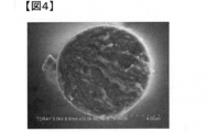
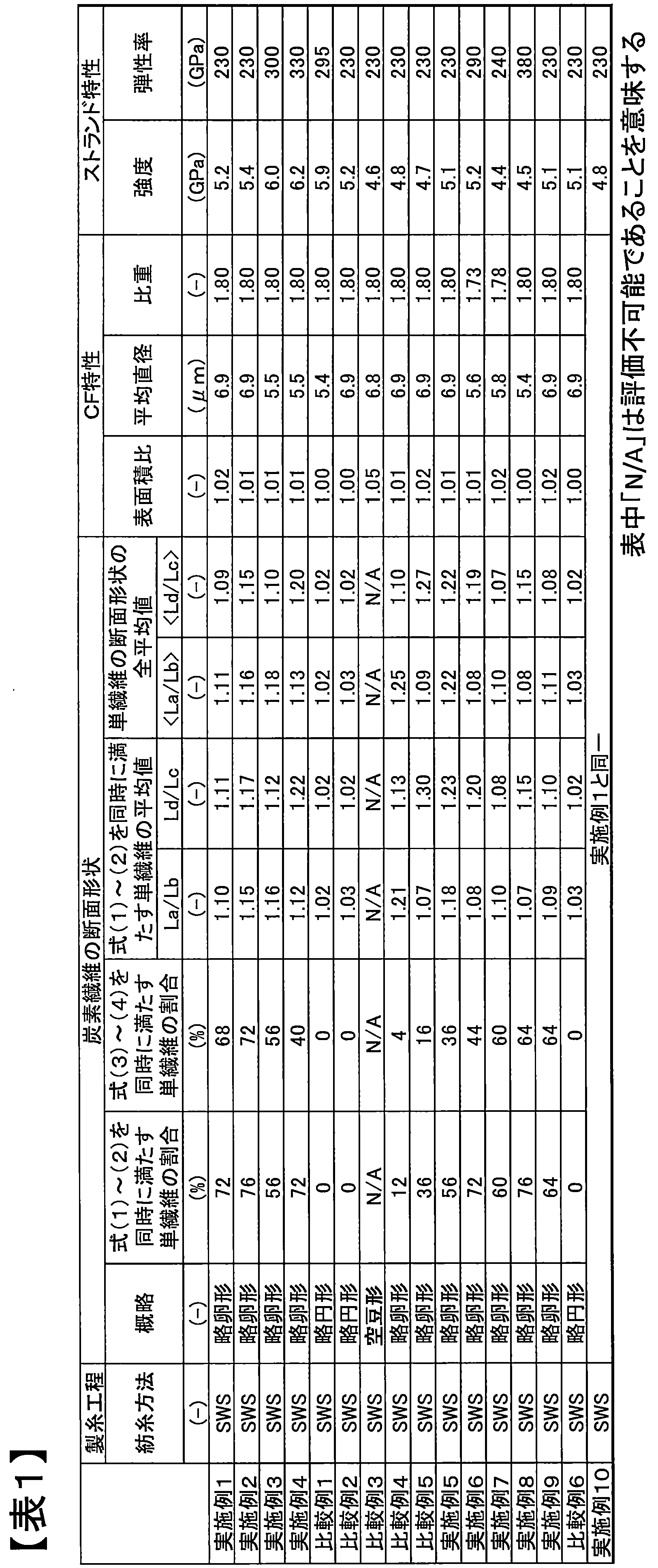
- the obtained carbon fiber bundle was evaluated for specific gravity, average diameter, strand strength, strand elastic modulus, cross-sectional shape, and surface area ratio. The evaluation results are shown in Table 1, and a cross-sectional SEM photograph is shown in FIG. Moreover, the cross-sectional shape was also evaluated about the flame-resistant fiber bundle. A cross-sectional SEM photograph is shown in FIG.
- Example 2 A polyacrylonitrile-based precursor fiber bundle was obtained in the same manner as in Example 1 except that the spinneret B was used, and the space through which the spinning solution was discharged from the nozzle was changed to about 4 mm. There was no particular problem in passing through the spinning process.
- a carbon fiber bundle was obtained in the same manner as in Example 1. The evaluation results are shown in Table 1, and a cross-sectional SEM photograph is shown in FIG. Moreover, the cross-sectional shape was also evaluated about the flame-resistant fiber bundle. The evaluation results are shown in Table 2.
- Example 3 A polyacrylonitrile-based precursor fiber bundle was obtained in the same manner as in Example 1 except that the single fiber fineness of the precursor fiber bundle was 0.7 dtex. There was no particular problem in passing through the spinning process.
- a carbon fiber bundle was obtained in the same manner as in Example 1 except that the maximum carbonization temperature was 1500 ° C. and the tension was 3.5 mN / dtex. The evaluation results are shown in Table 1.
- Example 4 A polyacrylonitrile-based precursor was used in the same manner as in Example 1 except that the spinneret C was used, the space through which the spinning solution was discharged from the nozzle was about 4 mm, and the single fiber fineness of the precursor fiber bundle was 0.7 dtex. A body fiber bundle was obtained. There was no particular problem in passing through the spinning process. A carbon fiber bundle was obtained in the same manner as in Example 1 except that the maximum carbonization temperature was 1500 ° C. and the tension was 5.2 mN / dtex. The evaluation results are shown in Table 1.
- Comparative Example 2 A polyacrylonitrile-based precursor fiber bundle was obtained in the same manner as in Comparative Example 1 except that the single fiber fineness of the precursor fiber bundle was 1.0 dtex. There was no particular problem in passing through the spinning process. A carbon fiber bundle was obtained in the same manner as in Example 1. The evaluation results are shown in Table 1. Moreover, the cross-sectional shape was also evaluated about the flame-resistant fiber bundle. The evaluation results are shown in Table 2.
- Example 4 A polyacrylonitrile-based precursor fiber bundle was obtained in the same manner as in Example 1 except that the space through which the spinning solution was discharged from the die was about 3 mm. There was no particular problem in passing through the spinning process. A carbon fiber bundle was obtained in the same manner as in Example 1. The evaluation results are shown in Table 1.
- Example 5 A polyacrylonitrile-based precursor fiber bundle was obtained in the same manner as in Example 1 except that the spinneret D was used and the space through which the spinning solution was discharged from the nozzle was set to about 3 mm. There was no particular problem in passing through the spinning process. A carbon fiber bundle was obtained in the same manner as in Example 1. The evaluation results are shown in Table 1.
- Example 5 A polyacrylonitrile-based precursor fiber bundle was obtained in the same manner as in Example 1 except that the spinneret C was used, and the space through which the spinning solution was discharged from the nozzle was changed to about 3 mm. There was no particular problem in passing through the spinning process. A carbon fiber bundle was obtained in the same manner as in Example 1. The evaluation results are shown in Table 1.
- Example 6 A polyacrylonitrile-based precursor fiber bundle was obtained in the same manner as in Example 4 except that the coagulation bath was a 30% dimethyl sulfoxide aqueous solution controlled at 15 ° C. There was no particular problem in passing through the spinning process. A carbon fiber bundle was obtained in the same manner as in Example 1 except that the maximum temperature in carbonization was 1800 ° C. The evaluation results are shown in Table 1.
- Example 7 Example except that the coagulation bath was an aqueous solution of 30% dimethyl sulfoxide controlled at 15 ° C., the space through which the spinning solution was discharged from the die was about 5 mm, and the single fiber fineness of the precursor fiber bundle was 0.7 dtex.
- a polyacrylonitrile-based precursor fiber bundle was obtained. There was no particular problem in passing through the spinning process.
- a carbon fiber bundle was obtained in the same manner as in Example 1 except that the maximum temperature in carbonization was 1000 ° C. The evaluation results are shown in Table 1.
- Example 8 In the same manner as in Example 6, a polyacrylonitrile-based precursor fiber bundle was obtained. There was no particular problem in passing through the spinning process. A carbon fiber bundle was obtained in the same manner as in Example 1 except that the maximum temperature in carbonization was 2400 ° C. The evaluation results are shown in Table 1.
- Example 9 Carbon fibers were obtained in the same manner as in Example 1 except that the tension in the steam drawing step in Example 1 was changed to 300 g. The evaluation results are shown in Table 1.
- Comparative Example 6 carbon fibers were obtained in the same manner as in Comparative Example 2 except that the tension in the steam drawing step was changed to 300 g. The evaluation results are shown in Table 1.
- Example 10 The carbon fiber bundle obtained in Example 1 was further subjected to electrolytic surface treatment with an electric amount of 200 C / g in a sulfuric acid aqueous solution having a conductivity of 10 mS. The evaluation results are shown in Table 1.
- Example 9 With respect to the carbon fiber bundles produced in Example 1, Example 9 and Example 10, a single fiber tensile test was carried out with a test length of 10 mm, the broken single fibers were collected, and the fracture surface was observed. The test was performed on 150 single fibers, and the fracture surfaces recovered were 79, 72, and 80, respectively. The position of the fracture start point was evaluated by SEM observation for each fracture surface. First, two major line segments were set by rotating the major axis in the direction of ⁇ 45 degrees around the intersection of the major axis and the minor axis.
- the arc including the substantially oval tip is assigned as A1, and A2, A3, and A4 are assigned clockwise.
- A1 the number of break start points existing in the arc A1 for all the single fibers observed by SEM was determined. The results were 19 for the carbon fiber bundle, 23 for the carbon fiber bundle of Example 9, and 21 for the carbon fiber bundle of Example 10. Dividing this by the total number of observations, the concentration of the breaking start point near the arc A1, that is, the vicinity of the substantially oval tip, is 24% with respect to the carbon fiber bundles of Example 1, Example 9, and Example 10, respectively. , 32% and 26% were obtained.
- Example 9 From the result of the evaluation of the break start point, it can be seen that the difference in distribution of the position of the break start point can be evaluated by using an approximately oval cross-sectional shape.
- Example 9 since the steam drawing was performed under a low tension, the fluctuation of the single fibers was increased, the contact between the single fibers and the inner wall of the steam drawing tube was increased, and the strand strength appeared to be slightly reduced. It was considered that defects were easily generated, and as a result, the concentration of the fracture start point was observed near the tip of the approximately oval shape.
- the comparative example 7 when the comparative example 7 is seen, the same strand strength fall is seen, and it can be judged that the strand strength fall by the cause estimated in Example 9 arises irrespective of a cross-sectional shape.
- Example 10 the electrolytic surface treatment was performed slightly excessively, and the strand strength was reduced, but the concentration of the break starting point was not observed. Therefore, when the carbon fiber bundle of the present invention is used, it can be said that the case where it occurs in the steam drawing step and the case where it occurs in the electrolytic treatment step can be distinguished from the same decrease in strand strength. Such analysis is impossible in principle with carbon fibers having a circular cross-sectional shape.
- Comparative Examples 4 to 6 when the content of single fibers satisfying the formulas (1) and (2) is low even if the shape of the cross section perpendicular to the fiber direction is substantially oval, the strand strength It turns out that falls. Comparative Examples 4 and 5 are cases in which the cross-sectional shape is flat, and Comparative Example 5 is a case in which the degree of flatness is low compared to these, but the substantially oval asymmetry is too strong, and is outside the scope of the present invention. It can be seen that the strand strength is reduced although it is generally oval and the position of the breaking start point can be easily distinguished.
- the carbon fiber bundle of the present invention and the carbon fiber bundle obtained from the flame-resistant fiber bundle of the present invention have a substantially oval cross-sectional shape without impairing strength, processability, and high-order workability compared to a circular cross section. Therefore, the relative position of the break start point can be evaluated by observing the single fiber fracture surface. As a result, when an abnormality occurs in the tensile strength of the carbon fiber bundle, which is a product, the cause can be grasped effectively, and a loss reduction effect due to opportunity loss can be expected, leading to a reduction in the carbon fiber manufacturing process.
Landscapes
- Engineering & Computer Science (AREA)
- Chemical & Material Sciences (AREA)
- Textile Engineering (AREA)
- Organic Chemistry (AREA)
- Chemical Kinetics & Catalysis (AREA)
- General Chemical & Material Sciences (AREA)
- Mechanical Engineering (AREA)
- Inorganic Chemistry (AREA)
- Inorganic Fibers (AREA)
- Health & Medical Sciences (AREA)
- Toxicology (AREA)
Abstract
Description
1.03≦La/Lb≦1.20 ・・・(1)
1.05≦Ld/Lc≦1.25 ・・・(2)
(ただし、単繊維の略卵形の断面の外周における最も離れた2点を通る線分を長軸、長軸の中点と外周上の2点を通り長軸に直交する線分を短軸と定義したとき、長軸の長さをLa、短軸の長さをLbとする。また、長軸を4等分した際に長軸の中点以外の点と外周上の2点をそれぞれ通り長軸に直交する2本の線分の長さを短いものから順にLc、Ldとする。)
また、繊維方向に垂直な断面の形状が略卵形であって、次式(1)および(2)を同時に満たす単繊維を70%以上含有する耐炎化繊維束も好ましい態様である。
1.03≦La/Lb≦1.20 ・・・(1)
1.05≦Ld/Lc≦1.25 ・・・(2)
(ただし、単繊維の略卵形の断面の外周における最も離れた2点を通る線分を長軸、長軸の中点と外周上の2点を通り長軸に直交する線分を短軸と定義したとき、長軸の長さをLa、短軸の長さをLbとする。また、長軸を4等分した際に長軸の中点以外の点と外周上の2点をそれぞれ通り長軸に直交する2本の線分の長さを短いものから順にLc、Ldとする。)
1.03≦La/Lb≦1.20 ・・・(1)
1.05≦Ld/Lc≦1.25 ・・・(2)
ただし、単繊維の略卵形の断面の外周における最も離れた2点を通る線分を長軸、長軸の中点と外周上の2点を通り長軸に直交する線分を短軸と定義したとき、長軸の長さをLa、短軸の長さをLbとする。また、長軸を4等分した際に長軸の中点以外の点と外周上の2点をそれぞれ通り長軸に直交する2本の線分の長さを短いものから順にLc、Ldとする。
1.04≦La/Lb≦1.17 ・・・(3)
1.05≦Ld/Lc≦1.20 ・・・(4)
La/Lbは1.04以上であるとさらに円形でないことの判断が容易となって好ましく、La/Lbが1.17以下、Ld/Lcが1.20以下であるとストランド強度の低下がさらに小さくなるために好ましい。
測定しようとする重合体が濃度0.1質量%でジメチルホルムアミド(0.01N-臭化リチウム添加)に溶解した検体溶液を作製した。前駆体繊維について測定する場合には、前駆体繊維を溶媒に溶解して前記検体溶液とする必要があるが、前駆体繊維は高度に配向し、緻密であるほど溶解しにくく、溶解時間が長いほど、また、溶解温度が高いほど低分子量に測定される傾向にあるので、前駆体繊維を微粉砕して、40℃の温度に制御された溶媒中においてスターラーで攪拌しながら1日溶解した。得られた検体溶液について、GPC装置を用いて、次の条件で測定したGPC曲線から分子量の分布曲線を求め、Mwおよびz平均分子量Mzを算出した。また、得られたMwおよびMzを用いてMz/Mwを算出した。
・カラム :極性有機溶媒系GPC用カラム
・流速 :0.5ml/min
・温度 :75℃
・試料濾過 :メンブレンフィルター(0.45μmカット)
・注入量 :200μl
・検出器 :示差屈折率検出器
MwおよびMzは、分子量が既知の単分散ポリスチレン標準試料を用いて通常の方法で作製した溶出時間―分子量の検量線を用いて溶出時間から計算されるポリスチレン換算値である。ただし、検量線は3次関数を用いた。
炭素繊維束の樹脂含浸ストランド引張強度と樹脂含浸ストランド引張弾性率は、JIS R7608:2007「樹脂含浸ストランド試験法」に準拠し、次の手順に従って求めた。測定する炭素繊維束の樹脂含浸ストランドは、3,4-エポキシシクロヘキシルメチル-3,4-エポキシシクロヘキシルカルボキシレート(100質量部)/3フッ化ホウ素モノエチルアミン(3質量部)/アセトン(4質量部)を、炭素繊維または黒鉛化繊維に含浸させ、125℃の温度で30分硬化させて作製した。炭素繊維の樹脂含浸ストランドの測定本数は6本とし、各測定結果の平均値を樹脂含浸ストランド引張強度とした。また、樹脂含浸ストランド引張弾性率を算出する歪み範囲は、単繊維繊度が1.0dtexの前駆体繊維束から得られた炭素繊維束については0.3%~0.7%、単繊維繊度が0.7dtexの前駆体繊維から得られた炭素繊維束については0.45%~0.85%とし、それぞれの歪み範囲における応力-歪み曲線を線形近似した際の傾きから樹脂含浸ストランド引張弾性率を算出した。本実施例では、3,4-エポキシシクロヘキシルメチル-3,4-エポキシシクロヘキシルカルボキシレートとして、ダイセル化学工業社製 “セロキサイド(登録商標)”2021Pを用いた。
測定する多数本の単繊維からなる炭素繊維束について、単位長さ当たりの質量Af(g/m)および比重Bf(-)を求めた。測定する炭素繊維束のフィラメント数をCfとし、単繊維の平均直径(μm)を、下記式で算出した。なお、下記式においては、近似的に比重Bfの値を、密度(g/cm3)の値として代用した。
・単繊維の平均直径(μm)=(Af/Bf/Cf/π)1/2×2×103。
炭素繊維束から単繊維を取り出し、繊維軸方向に引っ張ることで破断させた。破断により1本の繊維が2本になるが、片方は廃棄し、残った片方のみをSEM試料台にカーボンテープを用い、破断面が上を向くように貼り付けた。この操作を25回繰り返し、25本の単繊維を破断面が上を向くようにSEM試料台に貼り付けられたSEM試料を作製した。耐炎化繊維の場合は、100本程度の束を取り出して液体窒素に20秒間程度浸漬して凍結させたのち、取り出して握り鋏で挟み切って断面出しを行った。これを断面が上を向くように耐炎化繊維束を束ごとSEM試料台にカーボンテープを使って貼り付けた。いずれも、白金パラジウムを約10nmの厚みに真空蒸着してから、株式会社日立ハイテクノロジーズ社製S-4800走査型電子顕微鏡(SEM)により、加速電圧5.0kV、作動距離8mmの条件で観察した。
破断面のSEM観察像から長軸を決定した。その際、破断面の外周上の任意の2点を通る直線であって、最も長いものを長軸とした。かかる評価は目視で行うため、測定者により、また同一の測定者であっても評価時期により決定される長軸の角度が僅かに異なる可能性があるが、かかる要因によるばらつきは最大でも±10度程度と小さかったことから、同一の測定者が連続して2回評価した結果の平均を採用した。
測定にはオープンソースの画像解析ソフトウェア“ImageJ ver1.47”を用いた。長軸の長さLaは、(a)で決定した長軸の長さをピクセル単位で測定し、SEM観察像に付されたスケールバーを用いて実長さ(単位はμm)に換算した。次に長軸を4等分するように3つの点をおき、それぞれの点と繊維外周上の2点とを通る長軸と垂直な線分を3本求めた。これらのうち長軸の中点を通るものを短軸と定義し、短軸の長さLbをLaと同じ方法で求めた。残る2本の線分の長さをそれぞれLaと同じ方法で求め、短いものの長さをLc、長いものの長さをLdとした。
1.03≦La/Lb≦1.20 ・・・(1)
1.05≦Ld/Lc≦1.25 ・・・(2)
1.04≦La/Lb≦1.17 ・・・(3)
1.05≦Ld/Lc≦1.20 ・・・(4)。
上記のように求めた単繊維25本分のLa/LbおよびLd/Lcを、それぞれ単純平均をとって、<La/Lb>および<Ld/Lc>を計算した。また、式(1)および式(2)に該当する単繊維のみでLa/LbとLd/Lcの平均値を求めた。
評価すべき前駆体繊維単繊維を数本試料台にのせ、両端を接着液(例えば、文具の修正液)で固定したものをサンプルとし、原子間力顕微鏡(セイコーインスツルメンツ製、SPI3800N/SPA-400)を用い、下記条件にて3次元表面形状の像を得た。
・探針:シリコンカンチレバー(セイコーインスツルメンツ製、DF-20)
・測定モード:ダイナミックフォースモード(DFM)
・走査速度:1.5Hz
・走査範囲:3μm×3μm
・分解能:256ピクセル×256ピクセル。
[A]紡糸口金A:図2の(B)のタイプであって直径(d1)0.2mmの円孔と直径(d2)0.06mmの円孔とが中心間距離(L)0.16mmで穿孔された孔の組を100組有する紡糸口金を紡糸口金Aとした。
[B]紡糸口金B:図2の(B)のタイプであって直径(d1)0.2mmの円孔と直径(d2)0.06mmの円孔とが中心間距離(L)0.18mmで穿孔された孔の組を100組有する紡糸口金を紡糸口金Bとした。
[C]紡糸口金C:図2の(B)のタイプであって直径(d1)0.3mmの円孔と直径(d2)0.06mmの円孔とが中心間距離(L)0.22mmで穿孔された孔の組を100組有する紡糸口金を紡糸口金Cとした。
[D]紡糸口金D:図2の(B)のタイプであって直径(d1)0.3mmの円孔と直径(d2)0.04mmの円孔とが中心間距離(L)0.20mmで穿孔された孔の組を100組有する紡糸口金を紡糸口金Dとした。
[E]紡糸口金E:直径0.2mmの円孔を100個有する紡糸口金を紡糸口金Eとした。
アクリロニトリル99.5mol%とイタコン酸0.5mol%からなる共重合体を、ジメチルスルホキシドを溶媒とし、2,2’-アゾビスイソブチロニトリルを開始剤として溶液重合法により重合させ、重量平均分子量40万、Mz/Mwが2.1のポリアクリロニトリル系共重合体を製造した。製造されたポリアクリロニトリル系重合体に、アンモニアガスをpH8.5になるまで吹き込み、重合体の濃度が19質量%になるように調製して、紡糸溶液を得た。得られた紡糸溶液を、40℃で、紡糸口金Aを用い、一旦空気中に吐出し、約5mmの空間を通過させた後、5℃にコントロールした79%ジメチルスルホキシドの水溶液からなる凝固浴に導入する乾湿式紡糸法により凝固糸条とした。この凝固糸条を、常法により水洗した後、2槽の温水浴中で、3.5倍の延伸を行った。続いて、この水浴延伸後の繊維束に対して、アミノ変性シリコーン系のシリコーン油剤を付与し、160℃の加熱ローラーを用いて、乾燥緻密化処理を行った。5糸条を合糸し、単繊維の本数が500本の繊維束としてから、加圧スチーム中で500gの張力をかけながら3.7倍延伸することにより、製糸全延伸倍率を13倍とし、単繊維の繊度が1.0dtex、繊維束を構成する単繊維の本数が500本であるポリアクリロニトリル系前駆体の繊維束を得た。製糸工程の通過性は特に問題なかった。
紡糸口金Bを用い、紡糸溶液を口金から吐出した後通過させる空間を約4mmとした以外は、実施例1と同様にしてポリアクリロニトリル系前駆体繊維束を得た。製糸工程通過性は特に問題なかった。実施例1と同様にして炭素繊維束を得た。評価結果を表1に、断面のSEM写真を図6に示す。また、耐炎化繊維束についても、断面形状を評価した。評価結果を表2に示す。
前駆体繊維束の単繊維繊度を0.7dtexとした以外は実施例1と同様にしてポリアクリロニトリル系前駆体繊維束を得た。製糸工程通過性は特に問題なかった。炭素化処理の最高温度を1500℃、張力を3.5mN/dtexとした以外は実施例1と同様にして炭素繊維束を得た。評価結果を表1に示す。
紡糸口金Cを用い、紡糸溶液を口金から吐出した後通過させる空間を約4mmとし、前駆体繊維束の単繊維繊度を0.7dtexとした以外は、実施例1と同様にしてポリアクリロニトリル系前駆体繊維束を得た。製糸工程通過性は特に問題なかった。炭素化処理の最高温度を1500℃、張力を5.2mN/dtexとした以外は実施例1と同様にして炭素繊維束を得た。評価結果を表1に示す。
紡糸口金Eを用い、紡糸溶液を口金から吐出した後通過させる空間を約4mmとし、凝固浴を15℃にコントロールした30%ジメチルスルホキシドの水溶液とし、前駆体繊維束の単繊維繊度を0.7dtexとした以外は実施例1と同様にしてポリアクリロニトリル系前駆体繊維束を得た。製糸工程通過性は特に問題なかった。実施例1と同様にして炭素繊維束を得た。評価結果を表1に示す。
前駆体繊維束の単繊維繊度を1.0dtexとした以外は比較例1と同様にしてポリアクリロニトリル系前駆体繊維束を得た。製糸工程通過性は特に問題なかった。実施例1と同様にして炭素繊維束を得た。評価結果を表1に示す。また、耐炎化繊維束についても、断面形状を評価した。評価結果を表2に示す。
凝固浴を30℃にコントロールした55%ジメチルスルホキシドの水溶液とした以外は比較例2と同様にしてポリアクリロニトリル系前駆体繊維束を得た。製糸工程通過性は特に問題なかった。実施例1と同様にして炭素繊維束を得た。評価結果を表1に示す。
紡糸溶液を口金から吐出した後通過させる空間を約3mmとした以外は実施例1と同様にしてポリアクリロニトリル系前駆体繊維束を得た。製糸工程通過性は特に問題なかった。実施例1と同様にして炭素繊維束を得た。評価結果を表1に示す。
紡糸口金Dを用い、紡糸溶液を口金から吐出した後通過させる空間を約3mmとした以外は実施例1と同様にしてポリアクリロニトリル系前駆体繊維束を得た。製糸工程通過性は特に問題なかった。実施例1と同様にして炭素繊維束を得た。評価結果を表1に示す。
紡糸口金Cを用い、紡糸溶液を口金から吐出した後通過させる空間を約3mmとした以外は実施例1と同様にしてポリアクリロニトリル系前駆体繊維束を得た。製糸工程通過性は特に問題なかった。実施例1と同様にして炭素繊維束を得た。評価結果を表1に示す。
凝固浴を15℃にコントロールした30%ジメチルスルホキシドの水溶液とした以外は実施例4と同様にしてポリアクリロニトリル系前駆体繊維束を得た。製糸工程通過性は特に問題なかった。炭素化における最高温度を1800℃とした以外は実施例1と同様にして炭素繊維束を得た。評価結果を表1に示す。
凝固浴を15℃にコントロールした30%ジメチルスルホキシドの水溶液とし、紡糸溶液を口金から吐出した後通過させる空間を約5mmとし、前駆体繊維束の単繊維繊度を0.7dtexとした以外は実施例1と同様にしてポリアクリロニトリル系前駆体繊維束を得た。製糸工程通過性は特に問題なかった。炭素化における最高温度を1000℃とした以外は実施例1と同様にして炭素繊維束を得た。評価結果を表1に示す。
実施例6と同様にしてポリアクリロニトリル系前駆体繊維束を得た。製糸工程通過性は特に問題なかった。炭素化における最高温度を2400℃とした以外は実施例1と同様にして炭素繊維束を得た。評価結果を表1に示す。
実施例1においてスチーム延伸工程における張力を300gとした以外は、実施例1と同様にして炭素繊維まで得た。評価結果を表1に示す。
比較例2においてスチーム延伸工程における張力を300gとした以外は、比較例2と同様にして炭素繊維まで得た。評価結果を表1に示す。
実施例1において得られた炭素繊維束に、さらに伝導度10mSの硫酸水溶液中で電気量200C/gの電解表面処理を行った。評価結果を表1に示す。
実施例1、実施例9および実施例10で作製した炭素繊維束に関して試長10mmとして単繊維引張試験を実施し、破断した単繊維を回収し、その破断面を観察した。試験は150本の単繊維について行い、回収できた破断面はそれぞれ79本、72本、80本であった。各破断面についてSEM観察により破断開始点の位置を評価した。まず、長軸と短軸との交点を中心として長軸を±45度方向に回転させて新たに2本の線分を設定した。つぎに、かかる2本の線分によって繊維外周が4つの弧に分割できるので、略卵形の先端を含む弧をA1として、時計回りにA2、A3、A4と割り当てた。各単繊維について、破断開始点が弧A1からA4のいずれに存在するかを評価したあと、SEM観察した単繊維全部について弧A1に存在した破断開始点の数を求めたところ、実施例1の炭素繊維束では19本、実施例9の炭素繊維束では23本、実施例10の炭素繊維束では21本という結果であった。これを全体の観察数で割って弧A1、すなわち略卵形の先端近傍への破断開始点の集中度として、実施例1、実施例9、実施例10の炭素繊維束に対してそれぞれ24%、32%、26%との値を得た。

Claims (7)
- 繊維方向に垂直な断面の形状が略卵形であって、次式(1)および(2)を同時に満たす単繊維を40%以上含有する炭素繊維束。
1.03≦La/Lb≦1.20 ・・・(1)
1.05≦Ld/Lc≦1.25 ・・・(2)
(ただし、単繊維の略卵形の断面の外周における最も離れた2点を通る線分を長軸、長軸の中点と外周上の2点を通り長軸に直交する線分を短軸と定義したとき、長軸の長さをLa、短軸の長さをLbとする。また、長軸を4等分した際に長軸の中点以外の点と外周上の2点をそれぞれ通り長軸に直交する2本の線分の長さを短いものから順にLc、Ldとする。) - 次式(3)および(4)を同時に満たす単繊維を40%以上含有する請求項1記載の炭素繊維束。
1.04≦La/Lb≦1.17 ・・・(3)
1.05≦Ld/Lc≦1.20 ・・・(4) - 炭素繊維束中のそれぞれの単繊維における前記La/Lbおよび前記Ld/Lcの平均値をそれぞれ<La/Lb>および<Ld/Lc>としたとき、次式(5)および(6)を同時に満たす請求項1または2に記載の炭素繊維束。
<La/Lb>≦1.20 ・・・(5)
<Ld/Lc>≦1.20 ・・・(6) - 単繊維の平均直径が4~7μmである請求項1~3のいずれかに記載の炭素繊維束。
- 単繊維の表面積比の平均値が1.00~1.10である請求項1~4のいずれかに記載の炭素繊維束。
- ストランド強度が5GPa以上、かつストランド弾性率が230GPa以上である請求項1~5のいずれかに記載の炭素繊維束。
- 繊維方向に垂直な断面の形状が略卵形であって、次式(1)および(2)を同時に満たす単繊維を70%以上含有する耐炎化繊維束。
1.03≦La/Lb≦1.20 ・・・(1)
1.05≦Ld/Lc≦1.25 ・・・(2)
(ただし、単繊維の略卵形の断面の外周における最も離れた2点を通る線分を長軸、長軸の中点と外周上の2点を通り長軸に直交する線分を短軸と定義したとき、長軸の長さをLa、短軸の長さをLbとする。また、長軸を4等分した際に長軸の中点以外の点と外周上の2点をそれぞれ通り長軸に直交する2本の線分の長さを短いものから順にLc、Ldとする。)
Priority Applications (5)
| Application Number | Priority Date | Filing Date | Title |
|---|---|---|---|
| EP14832125.0A EP3029183B1 (en) | 2013-07-30 | 2014-07-29 | Carbon fiber bundle and flameproofed fiber bundle |
| CN201480041444.8A CN105408533B (zh) | 2013-07-30 | 2014-07-29 | 碳纤维束及耐燃化纤维束 |
| JP2014537206A JP5708896B1 (ja) | 2013-07-30 | 2014-07-29 | 炭素繊維束および耐炎化繊維束 |
| KR1020167001202A KR102189516B1 (ko) | 2013-07-30 | 2014-07-29 | 탄소 섬유 다발 및 내염화 섬유 다발 |
| US14/904,725 US11105022B2 (en) | 2013-07-30 | 2014-07-29 | Carbon fiber bundle and stabilized fiber bundle |
Applications Claiming Priority (2)
| Application Number | Priority Date | Filing Date | Title |
|---|---|---|---|
| JP2013157438 | 2013-07-30 | ||
| JP2013-157438 | 2013-07-30 |
Publications (1)
| Publication Number | Publication Date |
|---|---|
| WO2015016199A1 true WO2015016199A1 (ja) | 2015-02-05 |
Family
ID=52431732
Family Applications (1)
| Application Number | Title | Priority Date | Filing Date |
|---|---|---|---|
| PCT/JP2014/069890 Ceased WO2015016199A1 (ja) | 2013-07-30 | 2014-07-29 | 炭素繊維束および耐炎化繊維束 |
Country Status (6)
| Country | Link |
|---|---|
| US (1) | US11105022B2 (ja) |
| EP (1) | EP3029183B1 (ja) |
| JP (1) | JP5708896B1 (ja) |
| KR (1) | KR102189516B1 (ja) |
| CN (1) | CN105408533B (ja) |
| WO (1) | WO2015016199A1 (ja) |
Cited By (6)
| Publication number | Priority date | Publication date | Assignee | Title |
|---|---|---|---|---|
| JP2016030869A (ja) * | 2014-07-29 | 2016-03-07 | 東レ株式会社 | 炭素繊維束 |
| JP2021004437A (ja) * | 2015-03-12 | 2021-01-14 | サイテック インダストリーズ インコーポレイテッド | 中間弾性率炭素繊維の製造 |
| JP2023010616A (ja) * | 2021-07-09 | 2023-01-20 | 東レ株式会社 | サイジング剤含有炭素繊維束およびその製造方法 |
| JP2023033198A (ja) * | 2021-08-25 | 2023-03-09 | 臺灣塑膠工業股▲ふん▼有限公司 | 炭素繊維の製造方法 |
| US12234577B2 (en) * | 2015-10-08 | 2025-02-25 | Stora Enso Oyj | Process for the manufacture of a precursor yarn |
| WO2025243943A1 (ja) * | 2024-05-24 | 2025-11-27 | 東レ株式会社 | サイジング剤含有炭素繊維束、炭素繊維強化複合材料、圧力容器および圧力容器用サイジング剤含有炭素繊維束 |
Families Citing this family (3)
| Publication number | Priority date | Publication date | Assignee | Title |
|---|---|---|---|---|
| WO2016068034A1 (ja) | 2014-10-29 | 2016-05-06 | 東レ株式会社 | 炭素繊維束およびその製造方法 |
| WO2019244830A1 (ja) * | 2018-06-18 | 2019-12-26 | 東レ株式会社 | 炭素繊維およびその製造方法 |
| US20230267597A1 (en) * | 2022-02-24 | 2023-08-24 | Asahi Kasei Kabushiki Kaisha | Yarn inspection system and screening method |
Citations (6)
| Publication number | Priority date | Publication date | Assignee | Title |
|---|---|---|---|---|
| JPH02160911A (ja) * | 1988-08-25 | 1990-06-20 | Basf Ag | 良質炭素繊維への熱転化に特に適した高度に均一な内部構造を有する溶融紡糸アクリル繊維の製造に於ける改良 |
| JPH02242918A (ja) * | 1989-02-16 | 1990-09-27 | E I Du Pont De Nemours & Co | 改善されたピッチ炭素繊維紡糸法 |
| JPH0397918A (ja) | 1989-09-05 | 1991-04-23 | Toray Ind Inc | 異形断面炭素繊維の製造法 |
| JPH04202815A (ja) | 1990-11-29 | 1992-07-23 | Toray Ind Inc | 異形断面炭素繊維および炭素繊維強化複合材料 |
| JPH11302916A (ja) | 1998-04-27 | 1999-11-02 | Toray Ind Inc | 異形断面繊維の乾湿式紡糸口金 |
| JP2012188766A (ja) | 2011-03-09 | 2012-10-04 | Mitsubishi Rayon Co Ltd | 炭素繊維前駆体繊維束および炭素繊維束 |
Family Cites Families (9)
| Publication number | Priority date | Publication date | Assignee | Title |
|---|---|---|---|---|
| DE3686346T2 (de) * | 1985-04-23 | 1993-03-11 | Asahi Glass Co Ltd | Stoffbahn fuer gedruckte schaltungsplatte und gedruckte schaltungsplatte. |
| US5437927A (en) | 1989-02-16 | 1995-08-01 | Conoco Inc. | Pitch carbon fiber spinning process |
| GB2373256B (en) * | 2001-03-14 | 2005-03-30 | Du Pont | Fabrics comprising melt spun yarns having high lustre |
| EP1479797A1 (en) * | 2003-05-22 | 2004-11-24 | Landqart | Photoluminescent fibre, security paper and other security articles |
| JP5215073B2 (ja) * | 2008-07-31 | 2013-06-19 | 東レ株式会社 | 炭素繊維ウェブの製造方法 |
| JP4908636B2 (ja) * | 2009-06-10 | 2012-04-04 | 三菱レイヨン株式会社 | 機械的性能発現に優れた炭素繊維束 |
| US9074064B2 (en) * | 2010-12-13 | 2015-07-07 | Toray Industries, Inc. | Carbon fiber prepreg, method for producing same and carbon fiber reinforced composite material |
| KR20120111473A (ko) * | 2011-03-31 | 2012-10-10 | 코오롱인더스트리 주식회사 | 탄소섬유용 전구체 섬유 및 이의 제조방법 |
| EP3572564A1 (en) * | 2012-04-18 | 2019-11-27 | Mitsubishi Chemical Corporation | Carbon fiber bundle and method of producing carbon fibers |
-
2014
- 2014-07-29 JP JP2014537206A patent/JP5708896B1/ja active Active
- 2014-07-29 EP EP14832125.0A patent/EP3029183B1/en active Active
- 2014-07-29 US US14/904,725 patent/US11105022B2/en active Active
- 2014-07-29 CN CN201480041444.8A patent/CN105408533B/zh active Active
- 2014-07-29 WO PCT/JP2014/069890 patent/WO2015016199A1/ja not_active Ceased
- 2014-07-29 KR KR1020167001202A patent/KR102189516B1/ko active Active
Patent Citations (6)
| Publication number | Priority date | Publication date | Assignee | Title |
|---|---|---|---|---|
| JPH02160911A (ja) * | 1988-08-25 | 1990-06-20 | Basf Ag | 良質炭素繊維への熱転化に特に適した高度に均一な内部構造を有する溶融紡糸アクリル繊維の製造に於ける改良 |
| JPH02242918A (ja) * | 1989-02-16 | 1990-09-27 | E I Du Pont De Nemours & Co | 改善されたピッチ炭素繊維紡糸法 |
| JPH0397918A (ja) | 1989-09-05 | 1991-04-23 | Toray Ind Inc | 異形断面炭素繊維の製造法 |
| JPH04202815A (ja) | 1990-11-29 | 1992-07-23 | Toray Ind Inc | 異形断面炭素繊維および炭素繊維強化複合材料 |
| JPH11302916A (ja) | 1998-04-27 | 1999-11-02 | Toray Ind Inc | 異形断面繊維の乾湿式紡糸口金 |
| JP2012188766A (ja) | 2011-03-09 | 2012-10-04 | Mitsubishi Rayon Co Ltd | 炭素繊維前駆体繊維束および炭素繊維束 |
Non-Patent Citations (3)
| Title |
|---|
| "Resin impregnated strand test method", JIS R7608, 2007 |
| CARBON, vol. 41, 2003, pages 979 |
| See also references of EP3029183A4 |
Cited By (8)
| Publication number | Priority date | Publication date | Assignee | Title |
|---|---|---|---|---|
| JP2016030869A (ja) * | 2014-07-29 | 2016-03-07 | 東レ株式会社 | 炭素繊維束 |
| JP2021004437A (ja) * | 2015-03-12 | 2021-01-14 | サイテック インダストリーズ インコーポレイテッド | 中間弾性率炭素繊維の製造 |
| JP7225173B2 (ja) | 2015-03-12 | 2023-02-20 | サイテック インダストリーズ インコーポレイテッド | 中間弾性率炭素繊維の製造 |
| US12234577B2 (en) * | 2015-10-08 | 2025-02-25 | Stora Enso Oyj | Process for the manufacture of a precursor yarn |
| JP2023010616A (ja) * | 2021-07-09 | 2023-01-20 | 東レ株式会社 | サイジング剤含有炭素繊維束およびその製造方法 |
| JP2023033198A (ja) * | 2021-08-25 | 2023-03-09 | 臺灣塑膠工業股▲ふん▼有限公司 | 炭素繊維の製造方法 |
| US12006595B2 (en) | 2021-08-25 | 2024-06-11 | Formosa Plastics Corporation | Method for producing carbon fiber |
| WO2025243943A1 (ja) * | 2024-05-24 | 2025-11-27 | 東レ株式会社 | サイジング剤含有炭素繊維束、炭素繊維強化複合材料、圧力容器および圧力容器用サイジング剤含有炭素繊維束 |
Also Published As
| Publication number | Publication date |
|---|---|
| CN105408533A (zh) | 2016-03-16 |
| JP5708896B1 (ja) | 2015-04-30 |
| KR102189516B1 (ko) | 2020-12-11 |
| EP3029183A1 (en) | 2016-06-08 |
| KR20160037164A (ko) | 2016-04-05 |
| EP3029183A4 (en) | 2017-03-15 |
| JPWO2015016199A1 (ja) | 2017-03-02 |
| US20160168761A1 (en) | 2016-06-16 |
| EP3029183B1 (en) | 2018-08-29 |
| CN105408533B (zh) | 2017-05-31 |
| US11105022B2 (en) | 2021-08-31 |
Similar Documents
| Publication | Publication Date | Title |
|---|---|---|
| JP5708896B1 (ja) | 炭素繊維束および耐炎化繊維束 | |
| JP4924714B2 (ja) | 炭素繊維前駆体繊維および炭素繊維とその製造方法 | |
| JP6020201B2 (ja) | 炭素繊維束およびその製造方法 | |
| JP5434187B2 (ja) | ポリアクリロニトリル系連続炭素繊維束およびその製造方法 | |
| KR102194940B1 (ko) | 탄소 섬유 다발 및 그 제조 방법 | |
| KR20210019029A (ko) | 탄소 섬유 및 그의 제조 방법 | |
| KR102603178B1 (ko) | 탄소섬유 다발 및 그 제조 방법 | |
| JP5811305B1 (ja) | 炭素繊維およびその製造方法 | |
| JP2009197365A (ja) | 炭素繊維前駆体繊維の製造方法、及び、炭素繊維の製造方法 | |
| WO2019172247A1 (ja) | 炭素繊維束およびその製造方法 | |
| JP6295874B2 (ja) | 炭素繊維束 | |
| JP2009079343A (ja) | 炭素繊維用前駆体繊維および炭素繊維の製造方法 | |
| JP2007162144A (ja) | 炭素繊維束の製造方法 | |
| JP5504859B2 (ja) | 炭素繊維前駆体繊維束および炭素繊維束とそれらの製造方法 | |
| WO2016181845A1 (ja) | 合糸糸条束の製造方法および得られた合糸糸条束を用いる炭素繊維の製造方法 | |
| JP2014141760A (ja) | 炭素繊維束およびその製造方法 | |
| EP4379100A1 (en) | Carbon fiber bundle and production method for same | |
| JP6432396B2 (ja) | 炭素繊維 | |
| JP5146394B2 (ja) | 炭素繊維前駆体繊維の製造方法および炭素繊維の製造方法 | |
| JP2006283225A (ja) | 耐炎化繊維及び炭素繊維の製造方法 | |
| JP6881090B2 (ja) | 炭素繊維束 | |
| JP2017133123A (ja) | 炭素繊維およびその製造方法 | |
| JP2006274518A (ja) | 耐炎化繊維及び炭素繊維の製造方法 |
Legal Events
| Date | Code | Title | Description |
|---|---|---|---|
| WWE | Wipo information: entry into national phase |
Ref document number: 201480041444.8 Country of ref document: CN |
|
| ENP | Entry into the national phase |
Ref document number: 2014537206 Country of ref document: JP Kind code of ref document: A |
|
| 121 | Ep: the epo has been informed by wipo that ep was designated in this application |
Ref document number: 14832125 Country of ref document: EP Kind code of ref document: A1 |
|
| WWE | Wipo information: entry into national phase |
Ref document number: 2014832125 Country of ref document: EP |
|
| WWE | Wipo information: entry into national phase |
Ref document number: 14904725 Country of ref document: US |
|
| ENP | Entry into the national phase |
Ref document number: 20167001202 Country of ref document: KR Kind code of ref document: A |
|
| NENP | Non-entry into the national phase |
Ref country code: DE |