WO2015016244A1 - Dispositif de cellule solaire - Google Patents
Dispositif de cellule solaire Download PDFInfo
- Publication number
- WO2015016244A1 WO2015016244A1 PCT/JP2014/070016 JP2014070016W WO2015016244A1 WO 2015016244 A1 WO2015016244 A1 WO 2015016244A1 JP 2014070016 W JP2014070016 W JP 2014070016W WO 2015016244 A1 WO2015016244 A1 WO 2015016244A1
- Authority
- WO
- WIPO (PCT)
- Prior art keywords
- solar cell
- fixing member
- cell device
- roof
- support
- Prior art date
- Legal status (The legal status is an assumption and is not a legal conclusion. Google has not performed a legal analysis and makes no representation as to the accuracy of the status listed.)
- Ceased
Links
Images




Classifications
-
- F—MECHANICAL ENGINEERING; LIGHTING; HEATING; WEAPONS; BLASTING
- F24—HEATING; RANGES; VENTILATING
- F24S—SOLAR HEAT COLLECTORS; SOLAR HEAT SYSTEMS
- F24S25/00—Arrangement of stationary mountings or supports for solar heat collector modules
- F24S25/20—Peripheral frames for modules
-
- F—MECHANICAL ENGINEERING; LIGHTING; HEATING; WEAPONS; BLASTING
- F24—HEATING; RANGES; VENTILATING
- F24S—SOLAR HEAT COLLECTORS; SOLAR HEAT SYSTEMS
- F24S25/00—Arrangement of stationary mountings or supports for solar heat collector modules
- F24S25/30—Arrangement of stationary mountings or supports for solar heat collector modules using elongate rigid mounting elements extending substantially along the supporting surface, e.g. for covering buildings with solar heat collectors
- F24S25/33—Arrangement of stationary mountings or supports for solar heat collector modules using elongate rigid mounting elements extending substantially along the supporting surface, e.g. for covering buildings with solar heat collectors forming substantially planar assemblies, e.g. of coplanar or stacked profiles
- F24S25/35—Arrangement of stationary mountings or supports for solar heat collector modules using elongate rigid mounting elements extending substantially along the supporting surface, e.g. for covering buildings with solar heat collectors forming substantially planar assemblies, e.g. of coplanar or stacked profiles by means of profiles with a cross-section defining separate supporting portions for adjacent modules
-
- F—MECHANICAL ENGINEERING; LIGHTING; HEATING; WEAPONS; BLASTING
- F24—HEATING; RANGES; VENTILATING
- F24S—SOLAR HEAT COLLECTORS; SOLAR HEAT SYSTEMS
- F24S25/00—Arrangement of stationary mountings or supports for solar heat collector modules
- F24S25/60—Fixation means, e.g. fasteners, specially adapted for supporting solar heat collector modules
- F24S25/61—Fixation means, e.g. fasteners, specially adapted for supporting solar heat collector modules for fixing to the ground or to building structures
-
- F—MECHANICAL ENGINEERING; LIGHTING; HEATING; WEAPONS; BLASTING
- F24—HEATING; RANGES; VENTILATING
- F24S—SOLAR HEAT COLLECTORS; SOLAR HEAT SYSTEMS
- F24S20/00—Solar heat collectors specially adapted for particular uses or environments
- F24S2020/10—Solar modules layout; Modular arrangements
- F24S2020/14—Stepped arrangements, e.g. in parallel planes, without module overlapping
-
- F—MECHANICAL ENGINEERING; LIGHTING; HEATING; WEAPONS; BLASTING
- F24—HEATING; RANGES; VENTILATING
- F24S—SOLAR HEAT COLLECTORS; SOLAR HEAT SYSTEMS
- F24S25/00—Arrangement of stationary mountings or supports for solar heat collector modules
- F24S25/60—Fixation means, e.g. fasteners, specially adapted for supporting solar heat collector modules
- F24S2025/6005—Fixation means, e.g. fasteners, specially adapted for supporting solar heat collector modules by screwed connection
-
- Y—GENERAL TAGGING OF NEW TECHNOLOGICAL DEVELOPMENTS; GENERAL TAGGING OF CROSS-SECTIONAL TECHNOLOGIES SPANNING OVER SEVERAL SECTIONS OF THE IPC; TECHNICAL SUBJECTS COVERED BY FORMER USPC CROSS-REFERENCE ART COLLECTIONS [XRACs] AND DIGESTS
- Y02—TECHNOLOGIES OR APPLICATIONS FOR MITIGATION OR ADAPTATION AGAINST CLIMATE CHANGE
- Y02B—CLIMATE CHANGE MITIGATION TECHNOLOGIES RELATED TO BUILDINGS, e.g. HOUSING, HOUSE APPLIANCES OR RELATED END-USER APPLICATIONS
- Y02B10/00—Integration of renewable energy sources in buildings
- Y02B10/10—Photovoltaic [PV]
-
- Y—GENERAL TAGGING OF NEW TECHNOLOGICAL DEVELOPMENTS; GENERAL TAGGING OF CROSS-SECTIONAL TECHNOLOGIES SPANNING OVER SEVERAL SECTIONS OF THE IPC; TECHNICAL SUBJECTS COVERED BY FORMER USPC CROSS-REFERENCE ART COLLECTIONS [XRACs] AND DIGESTS
- Y02—TECHNOLOGIES OR APPLICATIONS FOR MITIGATION OR ADAPTATION AGAINST CLIMATE CHANGE
- Y02B—CLIMATE CHANGE MITIGATION TECHNOLOGIES RELATED TO BUILDINGS, e.g. HOUSING, HOUSE APPLIANCES OR RELATED END-USER APPLICATIONS
- Y02B10/00—Integration of renewable energy sources in buildings
- Y02B10/20—Solar thermal
-
- Y—GENERAL TAGGING OF NEW TECHNOLOGICAL DEVELOPMENTS; GENERAL TAGGING OF CROSS-SECTIONAL TECHNOLOGIES SPANNING OVER SEVERAL SECTIONS OF THE IPC; TECHNICAL SUBJECTS COVERED BY FORMER USPC CROSS-REFERENCE ART COLLECTIONS [XRACs] AND DIGESTS
- Y02—TECHNOLOGIES OR APPLICATIONS FOR MITIGATION OR ADAPTATION AGAINST CLIMATE CHANGE
- Y02E—REDUCTION OF GREENHOUSE GAS [GHG] EMISSIONS, RELATED TO ENERGY GENERATION, TRANSMISSION OR DISTRIBUTION
- Y02E10/00—Energy generation through renewable energy sources
- Y02E10/40—Solar thermal energy, e.g. solar towers
- Y02E10/47—Mountings or tracking
-
- Y—GENERAL TAGGING OF NEW TECHNOLOGICAL DEVELOPMENTS; GENERAL TAGGING OF CROSS-SECTIONAL TECHNOLOGIES SPANNING OVER SEVERAL SECTIONS OF THE IPC; TECHNICAL SUBJECTS COVERED BY FORMER USPC CROSS-REFERENCE ART COLLECTIONS [XRACs] AND DIGESTS
- Y02—TECHNOLOGIES OR APPLICATIONS FOR MITIGATION OR ADAPTATION AGAINST CLIMATE CHANGE
- Y02E—REDUCTION OF GREENHOUSE GAS [GHG] EMISSIONS, RELATED TO ENERGY GENERATION, TRANSMISSION OR DISTRIBUTION
- Y02E10/00—Energy generation through renewable energy sources
- Y02E10/50—Photovoltaic [PV] energy
Definitions
- the present invention relates to a solar cell device.
- the solar cell device used for this photovoltaic power generation is installed on the roof of a building, for example. Therefore, the solar cell device is required to have a structure suitable for the characteristics of the roof.
- a horizontal roof as a kind of roof.
- an engagement part is provided on the long side of a long sheet metal roof material, and the engagement parts are engaged with each other so that the long side is orthogonal to the inclination direction of the roof.
- the structure is arranged in a staircase pattern.
- Japanese Patent Application Laid-Open No. 2011-117204 discloses a solar cell device having a structure in which a draining cover that covers the top of a support fitting fixed to a side roof and a draining plate disposed on the bottom side of the support fitting.
- the solar cell device disclosed in Japanese Patent Application Laid-Open No. 2011-117204 has a structure in which the load of the solar cell device is supported by the field plate by disposing a support bracket on the roof material where the roof material and the field plate are in contact with each other. It is.
- a backup material or a heat insulating material made of foamed polystyrene, glass fiber, or the like may be provided in this space.
- the roofing material of the side roof may be deformed, the engagement portion may be disengaged, and water leakage may occur.
- One object of the present invention is to provide a solar cell device in which the deformation of the roof material is reduced by reducing the load applied to the roof material due to its own weight or the like.
- the solar cell device is installed on the installation surface via a roofing material.
- the solar cell device includes a solar cell module, a support member that supports the solar cell module, a bottom surface portion that is provided between the support member and the roof material, and is disposed on the roof material. And a support bracket. Further, in the present embodiment, a first fixing member that fixes the support fitting to the installation surface by penetrating the bottom surface portion and the roof material and inserting the roof member into the installation surface, and an upper end of the first fixing member. A second fixing member that covers and is fixed to the upper surface of the bottom surface portion.
- the solar cell device has a structure that can be supported not only by the roofing material but also by the installation surface, and thus the external force such as the solar cell device's own weight or snow load is dispersed and the roof. It becomes difficult to concentrate on the material. Thereby, in this embodiment, the deformation
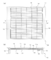
- FIG. 2 is a cross-sectional view showing a cross section AA ′ of FIG. 1 is a drawing of a solar cell device 1A according to a first embodiment of the present invention, and is a cross-sectional view showing a B-B ′ cross section of FIG.
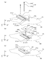
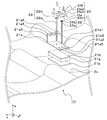
- FIG. 4 It is drawing which shows 1 A of solar cell apparatuses which concern on 1st Embodiment of this invention, (a) is a disassembled perspective view which extracts and shows the C section of FIG. 3, (b) extracts C section of FIG. It is a perspective view shown. It is drawing which shows the solar cell apparatus 1B which concerns on 2nd Embodiment of this invention, (a) is a disassembled perspective view equivalent to Fig.4 (a), (b) is a perspective view equivalent to FIG.4 (b). FIG. It is drawing which shows the modification of the solar cell apparatus 1B which concerns on 2nd Embodiment of this invention, (a) is a disassembled perspective view equivalent to Fig.4 (a), (b) is FIG.4 (b). FIG.
- FIG. 6C is a corresponding perspective view, and FIG. 6C is a cross-sectional view of FIG. 6B viewed from the DD ′ cross section. It is drawing which shows 1 C of solar cell apparatuses which concern on 3rd Embodiment of this invention, and is sectional drawing equivalent to FIG. It is drawing which shows 1D of solar cell apparatuses which concern on 4th Embodiment of this invention, and is sectional drawing equivalent to FIG. It is drawing which shows the solar cell apparatus 1E which concerns on 5th Embodiment of this invention, and is sectional drawing equivalent to FIG. It is drawing which shows the solar cell apparatus 1F which concerns on 6th Embodiment of this invention, and is a disassembled perspective view equivalent to Fig.4 (a).
- FIG. 4 It is drawing which shows 1 G of solar cell apparatuses which concern on 7th Embodiment of this invention, (a) and (b) is a disassembled perspective view which shows the assembly order of FIG.11 (b), (c) is FIG. It is a perspective view equivalent to (b). It is drawing which shows the modification of the solar cell apparatus 1G which concerns on 7th Embodiment of this invention, and is a perspective view equivalent to FIG.4 (b). It is drawing which shows the solar cell apparatus 1H which concerns on 8th Embodiment of this invention, and is a disassembled perspective view equivalent to Fig.4 (a).
- solar cell device 1 ⁇ / b> A is fixed on an inclined roof 2.
- the roof 2 includes a plurality of structural members 2a arranged in parallel to each other, a field plate 2b that is inclined and fixed on the structure material 2a, and a roof material 2c that is wound on the field plate 2b.
- the base plate 2b corresponds to a roof base material.
- the roofing material 2c is, for example, a rectangular plate, and has engaging portions 2c1 at the edges of the long sides on both sides.
- the roof material 2c is made of, for example, a metal roofing material. Specifically, for the roofing material 2c, for example, an aluminum-zinc alloy plated steel plate, a stainless steel plate, or the like is used.
- the roof 2 is configured by arranging such a roofing material 2c in a stepwise manner adjacent to the eaves direction so that the direction perpendicular to the slope of the field board 2b is the longitudinal direction. At this time, the engaging portions 2c1 of the adjacent roof materials 2c are engaged with each other.
- the roof 2 is, for example, a horizontal roof in which a sheet metal roofing material 2c is laid on the field board 2b, imitating a tiled roof. Therefore, the roof 2 has a space 2d between the field board 2b and the roofing material 2c.
- the field plate 2b is also referred to as an installation surface 2b.
- the solar cell device 1 ⁇ / b> A includes a solar cell module 10, a support member 21, a support fitting 21 a, a first fixing member 22, and a second fixing member 23.
- the support member 21 is supported by a support fitting 21a provided between the support member 21 and the roofing material 2c.
- the support fitting 21a is fixed to the installation surface 2b by the first fixing member 22.
- the 2nd fixing member 23 is fixed to the upper surface of the bottom face part 21a1 of the support metal fitting 21a.
- the inclination direction of the roof 2 is the y-axis direction
- the normal direction to the roof 2 is the z-axis direction
- the direction perpendicular to the y-axis direction and the z-axis direction is the x-axis direction.
- the direction from the roof 2 toward the solar cell device 1 is referred to as a + z-axis direction or upward
- the opposite direction is referred to as a ⁇ z-axis direction or downward.
- the plurality of solar cell modules 10 are arranged along the x-axis direction and the y-axis direction.
- the solar cell module 10 includes a solar cell panel 11 and a frame 12 that reinforces the outer edge portion of the solar cell panel 11.
- the solar cell panel 11 includes a light receiving surface 11a (one main surface of the translucent substrate 13) that mainly receives light, and a back surface 11b (back surface) located on the back side of the light receiving surface 11a.
- the solar cell panel 11 is surrounding to the sealing material 14 in order from the light-receiving surface 11a side, the translucent board
- the solar cell panel 11 includes a back surface protection member 17 for protecting the back surface of the solar cell module 10 and a terminal box 18 for taking out the output obtained by the solar cell element 16 to the outside.
- the back surface 11b may be formed of a material having translucency, for example, the back surface protection member 17 and the sealing material 14 positioned between the solar cell element 16 and the back surface protection member 17. Thereby, light can be received also from the back surface 11b side of the solar cell panel 11. As a result, the photoelectric conversion efficiency of the solar cell panel is improved.
- the solar cell element 16 is a flat substrate made of, for example, single crystal silicon or polycrystalline silicon. When such a silicon substrate is used, the adjacent silicon substrates may be electrically connected by the inner leads 15 as described above.
- the solar cell element 16 may be, for example, a thin film solar cell element made of amorphous silicon, a CIGS solar cell element, a CdTe solar cell element, or a solar cell element 16 in which a thin film amorphous is formed on a crystalline silicon substrate. Good. Further, for example, as the solar cell element 16 made of amorphous silicon, CIGS, and CdTe, the amorphous silicon layer, the CIGS layer, and the CdTe layer are appropriately laminated in combination with a transparent electrode or the like on the translucent substrate 13. Things are available.
- the terminal box 18 includes a modified polyphenylene ether resin or polyphenylene oxide resin box, a terminal plate disposed in the box, and an output cable for leading electric power to the outside of the box.
- the frame 12 has a function of holding the solar cell panel 11.
- the frame 12 can be manufactured by extruding aluminum.
- the support member 21 includes a first adhesive member 21b, a vertical rail 21c, a horizontal rail 21d, a first fastening member 21e, and a second fastening member 21f.
- the vertical rails 21c and the horizontal rails 21d are assembled in a lattice shape on the support bracket 21a.
- the vertical rail 21c and the horizontal rail 21d are fixed by the first fastening member 21e and the second fastening member 21f.
- the solar cell module 10 is fixed to the vertical rail 21c and the horizontal rail 21d.
- the support fitting 21a is a member formed by bending a part of a plate material, for example, as shown in FIGS.
- the support fitting 21a is substantially parallel to the bottom surface portion 21a1 from the upper end of the vertical portion 21a3, the bottom surface portion 21a1 arranged on the roofing material 2c, the vertical portion 21a3 erected substantially vertically from the bottom surface portion 21a1.
- an upper side portion 21a4 disposed on the side.
- the length of the upper side portion 21a4 is shorter than the length of the bottom surface portion 21a1 in the y-axis direction.
- the support bracket 21a supports the vertical rail 21c and the horizontal rail 21d with the upper side portion 21a4.
- the bottom surface portion 21 a 1 has a first through hole 21 a 2 having a diameter larger than that of the first fixing member 22.
- the 1st fixing member 22 can insert the 1st through-hole 21a2, and can fix the support metal fitting 21a to the installation surface 2b.
- the bottom surface portion 21a1 has a screw hole portion 21a5 in which a screw 23b for fixing the second fixing member 23 is fastened in the vicinity of the first through hole 21a2.
- the screw hole portion 21a5 has a female screw that engages with the screw 23b on the inner wall thereof.
- the upper side portion 21a4 supports the support member 21 (vertical rail 21c) from the lower side.
- the upper side part 21a4 has the 2nd through-hole 21a6 for inserting the 1st fastening member 21e and fixing the vertical rail 21c.
- Such a support fitting 21a can be manufactured, for example, by roll forming or bending a stainless steel plate or a plated steel plate. Moreover, you may manufacture by extruding metals, such as an aluminum alloy.
- the first fixing member 22 is fastened to the installation surface 2b through the first through hole 21a2 of the bottom surface portion 21a1 of the support fitting 21a and the roof material 2c. At this time, the 1st fixing member 22 will penetrate the bottom face part 21a1 and the roofing material 2c, and will be inserted in the said setting surface. Thereby, the 1st fixing member 22 is fixing the support metal fitting 21a to the roof 2 (installation surface 2b).
- the first fixing member 22 has a male screw portion 22a formed at a portion including one end portion located on the ⁇ z-axis direction side.
- the first fixing member 22 has a head portion 22b corresponding to the upper end of the first fixing member 22 on the other end side located on the + z-axis direction side.
- the male screw portion 22a has a length that reaches at least the installation surface 2b from the bottom surface portion 21a1 of the support fitting 21a.
- the male screw portion 22a may have a length until it reaches the structural material 2a.
- the head portion 22b is in contact with the upper surface of the bottom surface portion 21a1 of the support fitting 21a.
- a wood screw can be used for the first fixing member 22.
- the 1st fixing member 22 if it is a material which has corrosion resistance and intensity
- the second fixing member 23 covers the upper end (head 22b) of the first fixing member 22 and is fixed to the upper surface of the bottom surface portion 21a1. Thereby, the second fixing member 23 can prevent the first fixing member 22 from moving in the + z-axis direction.
- the second fixture 23 has a substantially plate-like contact member 23a and a screw 23b. The contact member 23a is fixed to the bottom surface portion 21a1 with a screw 23b.
- the contact member 23 a has a first recess 23 a 1 into which the head 22 b enters in a main surface facing the head 22 b of the first fixing member 22. Moreover, it has the 3rd through-hole 23a2 which can insert the screw 23b in the both sides of 1st recessed part 23a1. And the contact member 23a can pinch
- release from the installation surface 2b of the 1st fixing member 22 which arises when the 1st fixing member 22 moves to + z-axis direction can be reduced.
- Such a contact member 23a can be formed by, for example, extrusion molding of an aluminum alloy or press forming of a metal plate such as stainless steel or galvanized steel plate.
- the screw 23b may be formed of the same material as that of the first fixing member 22.
- the first adhesive member 21b is provided between the bottom surface portion 21a1 of the support fitting 21a and the roofing material 2c. Thereby, the 1st adhesion member 21b bears the role which protects the circumference of the fixed part of support bracket 21a from rain water and moisture, when supporting bracket 21a is fixed to roof 2.
- a butyl rubber sheet or the like can be cut into a strip shape and used.
- the vertical rail 21c is, for example, a long rail having a substantially rectangular cross section.
- the vertical rail 21c has a length that is substantially an integral multiple of the length of the solar cell module 10 in the y-axis direction.
- the vertical rail 21 c is provided on the support fitting 21 a so that the longitudinal direction thereof is substantially parallel to the inclination direction of the roof 2.
- the vertical rail 21c is fixed to the support fitting 21a by the first fastening member 21e.
- Such a vertical rail member 21c can be formed by, for example, extrusion molding of an aluminum alloy or roll forming of SUS or steel.
- the horizontal rail 21d is, for example, a long rail having a substantially rectangular cross section. Further, the horizontal rail 21d has a length that is substantially an integral multiple of the length of the solar cell module 10 in the x-axis direction.
- the horizontal rail 21d is provided on the vertical rail 21c so that its longitudinal direction is substantially perpendicular to the inclination direction of the roof 2. At this time, the horizontal rail 21d is fixed to the vertical rail 21c by the second fastening member 21f. And the solar cell module 10 is fixed on the horizontal rail 21d.
- Such a horizontal rail 21d can be formed of the same material and method as the vertical rail member 21c.
- the first fastening member 21e is composed of, for example, a bolt and a nut.
- the first fastening member 21e has a role of inserting the second through hole 21a6 of the support fitting 21a and fixing the vertical rail 21c to the upper side portion 21a4 of the support fitting 21a.
- the second fastening member 21f is constituted by, for example, a bolt.
- the second fastening member 21f has a role of fixing the horizontal rail 21d to the vertical rail 21c using a metal fitting or the like.
- Such first fastening member 21e and second fastening member 21f may be formed of the same material as that of the first fixing member 22, for example.
- the solar cell device 1A fixes the support fitting 2a to the installation surface 2b by passing through the bottom surface portion 21a1 and the roofing material 2c of the support fitting 21a and inserting it into the installation surface 2b.
- a second fixing member 23 that covers the upper end of the first fixing member 22 and is fixed to the upper surface of the bottom surface portion 21a1.
- the solar cell device 1 can be supported not only by the roofing material 2c but also by the installation surface 2b. It becomes. Therefore, the external force is less likely to concentrate on the roofing material 2c. Thereby, in this embodiment, the deformation
- the roof material 2c of the roof 2 that is relatively easily deformed can be protected from the above-described own weight or snow load. Thereby, the waterproofness of the roof 2 can be maintained.
- the 1st fixing member 22 uses the wood screw which has the external thread part 22a, it can construct by screwing in from the surface of the roofing material 2c. Thereby, when constructing the solar cell device 1 ⁇ / b> A on the roof 2, it is not necessary to remove the roof material 2 c once and install a metal fitting or the like. As a result, the workability of the solar cell device 1A is improved.
- the solar cell module 1B according to the second embodiment differs from the first embodiment in the structure of the bottom surface portion 21a1 to which the second fixing member 23 is fixed.
- the support fitting 21a in the present embodiment has a protruding portion 21a7 that extends from a portion of the peripheral portion of the bottom surface portion 21a1 so as to cover a portion of the upper surface of the second fixing member 23.
- the support fitting 21a has protruding portions 21a7 that protrude from the bottom surface portion 21a1 to the upper side portion 21a4 side at both ends (both sides) of the bottom surface portion 21a1 in the x-axis direction.
- the protruding portion 21a7 has, for example, a shape bent upward in a U shape. Thereby, the plate-like second fixing member 23 can be inserted into the groove portion 21a9 formed between the bottom surface portion 21a1 and the protruding portion 21a7. As a result, since the protruding portion 21a7 is positioned on the upper surface of the second fixing member 23, the second fixing member 23 is fixed to the support fitting 21a.
- the upper surface of the second fixing member 23 refers to a surface located on the opposite side to the surface that contacts the bottom surface portion 21a1.
- the screw 23b can be omitted from the second fixing member 23
- the second fixing member 23 can be slid and inserted and fixed.
- the protruding portion 21a7 may be formed so as to provide a slight clearance with a part of the upper surface of the second fixing member 23, but may be in contact with the upper surface of the second fixing member 23. If it is such a form, the 2nd fixing member 23 can be fixed by protrusion part 21a7.
- the second fixing member 23 has a first recess 23a1 at a portion that contacts the head 22b of the first fixing member 22.
- the support fitting 21a shown in FIG. 6 is formed inside the second recess 21a8 in which the protrusion 21a7 is inserted and engaged with the head of the bolt 21e1 of the first fastening member 21e. Therefore, the second fixing member 23 is slid and inserted into the groove 21a9 formed by the protruding portion 21a7, so that the head portion 22b of the first fixing member 22 is sandwiched between the bottom surface portion 21a1 and the second fixing member 23. Can be fixed. Thereby, the load added to the roofing material 2c of the roof 2 can be reduced more.
- such a support metal fitting 21a can be produced by extruding a metal such as an aluminum alloy, for example.
- the solar cell device 1 ⁇ / b> C according to the third embodiment is different from the above-described configuration in the structure in which the bottom surface portion 21 a 1 is fixed to the roof material 2 c.
- the support metal fittings 21a in the present embodiment are arranged on the roof material 2c whose bottom surface portion 21a1 is adjacent in the y-axis direction when a plurality of the roof materials 2c are arranged in a plane so as to cover the installation surface 2b. It is arranged across.
- the 2nd fixing member 23 is fixed on the head 22b of the 1st fixing member 22 which penetrates the 1st through-hole 21a2 of the bottom face part 21a1.
- the structure of the support metal fitting 21a is not limited to the structure in which the bottom surface portion 21a1 is installed on the single roof material 2c, and can be applied to a case where the structure extends over the plurality of roof materials 2c.
- the solar cell device 1C has a structure in which the horizontal rail 21d is fixed on the support fitting 21a.
- the present embodiment is not limited to the structure in which the vertical rails 21c and the horizontal rails 21d are assembled in a grid pattern. As shown in FIG. 7, the horizontal rails 21d are directly fixed on the support bracket 21a. It can also be applied to other structures.
- the solar cell device 1D according to the fourth embodiment differs from the other embodiments in the structure on the lower side of the installation surface 2b.
- this embodiment is a structure in which a reinforcing member 24 is provided below the installation surface 2b of the roof 2 without the structural material 2a. Therefore, the reinforcing member 24 is disposed so as to contact the back surface (lower surface) of the base material having the installation surface 2b. More specifically, in the present embodiment, the reinforcing member 24 is fixed by inserting the first fixing member 22 that is in contact with the back surface of the base material (the base plate 2b) and penetrates the base plate 2b. In addition, it is located in the reverse side with respect to the surface where the roofing material 2c is arrange
- the roof 2 without the structural material 2a may have insufficient mounting strength for the first fixing member 22. Therefore, in the present embodiment, by providing the reinforcing member 24, the mounting strength of the first fixing member 22 can be increased and the installation strength of the solar cell device 1D can be increased. Thereby, the fall of the waterproof performance of the roof 2 accompanying the failure
- the reinforcing member 24 may be fixed to the lower side of the installation surface 2b with an adhesive 25 or a wood screw 26, for example, in order to increase the physical integration with the installation surface 2b (field plate) and increase the strength.
- the solar cell device 1 ⁇ / b> E according to the fifth embodiment is different in the structure of the first fixing member 22 and the second fixing member 23 from the above-described embodiment.
- the solar cell device 1E includes a first fixing member 22 and a second fixing member 23, and includes a third fixing member 27 configured by a single screw.
- the third fixing member 27 has a tip portion and a head portion.
- the 3rd fixing member 27 has the 1st screw part 27a which consists of a thread of a tapping screw which can be fastened with installation surface 2b in the tip part side.
- the outer diameter of the first screw portion 27a is smaller than the first through hole 21a2 of the bottom surface portion 21a1.
- the second screw portion 27b is provided closer to the head than the first screw portion 27a.
- the outer diameter of the second screw portion 27b is larger than that of the first screw portion 27a and is approximately the same diameter as the first through hole 21a2 of the bottom surface portion 21a1. is there.
- the second screw portion 27b can be engaged and fixed with a female screw formed in the first through hole 21a1.
- the first screw portion 27 a corresponds to the first fixing member 22, and the second screw portion 27 b corresponds to the second fixing member 23.
- first screw portion 27a and the second screw portion 27b are preferably set to the same pitch. Thereby, when the 1st screw part 27a and the 2nd screw part 27b engage with a female screw simultaneously, the distance which advances in each screw part becomes the same, and damage to roof 2 or bottom 21a1 can be reduced. Thus, in the solar cell device 1E, since the first fixing member 22 and the second fixing member 23 are integrated, the number of parts can be reduced and the workability can be further improved.
- the solar cell device 1 ⁇ / b> F according to the sixth embodiment is different in the structure of the bottom surface portion 21 a 1 of the support fitting 21 a from the above-described embodiment.
- the bottom surface portion 21a1 of the support fitting 21a in the present embodiment has a concave portion (third concave portion 21a10) where the upper end of the first fixing member 22 is located on the upper surface. Therefore, the 1st fixing member 22 penetrates the roof material 2c through the 1st through-hole 21a2 provided in the bottom face of the 3rd recessed part 21a10, and is inserted in the installation surface 2b.
- the depth of the third recess 21 a 10 in the z-axis direction may be approximately the same as the height of the head 22 b corresponding to the upper end of the first fixing member 22.
- the support fitting 21a has a screw hole 21a5 at a place other than the portion where the third recess 21a10 is provided.
- the 2nd fixing member 23 inserts the screw 23b in the 3rd through-hole 23a2 provided in the position corresponding to the screw hole part 21a5, and fastens it to the screw hole part 21a5, and thereby the bottom face part 21a1 of the support metal fitting 21a. Fixed to.
- the first fixing member 22 has a structure in which the upper end of the first fixing member 22 enters the recess (the third recess 21a10). Therefore, the first fixing member 23 shown in FIG. The recess 23a1 becomes unnecessary. Therefore, in this embodiment, as shown in FIG. 10, a flat plate-like general member provided with the third through hole 23 a 2 can be used as the contact member 23 a of the second fixing member 23. Thus, in this embodiment, since the structure of the 2nd fixing member 23 can be simplified, workability
- the solar cell device 1 ⁇ / b> G according to the seventh embodiment is different from the above-described embodiment in the structure of the second fixing member 23.
- the 2nd fixing member 23 in this embodiment has the convex part (1st convex part 23a3) inserted in the recessed part (3rd recessed part 21a10) of the support metal fitting 21a on the lower surface.
- the positioning of the second fixing member 23 with respect to the support fitting 21a is facilitated when the solar cell device 1G is constructed. Therefore, in this embodiment, since it becomes easy to fix the 2nd fixing member 23 to the support metal fitting 21a using the screw 23b and the nut 23d, workability
- the screw 23b in the present embodiment greatly extends in the + z-axis direction as compared with the screw 23b in the first embodiment.
- the screw 23b in this embodiment is longer in the z-axis direction than the screw 23b in the first embodiment.
- the screw 23b of this embodiment can be used not only for fixing the contact member 23a but also the vertical rail 21c. Therefore, the screw 23b of the present embodiment also functions as the first fastening member 21e in the first embodiment.
- the second fixing member 23 may have a plurality of screws 23b. Therefore, since the contact member 23a can be firmly fixed, deformation of the contact member 23a caused by a load pushed up in the + z-axis direction by the first fixing member 22 is less likely to occur.
- the support fitting 21a and the second fixing member 23 (abutting member 23a) in the sixth and seventh embodiments can be easily manufactured by, for example, extrusion molding a metal such as an aluminum alloy.
- the solar cell device 1H according to the eighth embodiment is different from the above-described embodiment in that an elastic member 21g is provided between the bottom surface portion 21a1 of the support fitting 21a and the roofing material 2c.
- the roofing material 2c uses western tiles called Spanish tiles.
- the first adhesive member 21b is provided between the elastic member 21g and the roofing material 2c.
- the 1st fixing member 22 penetrates the elastic member 21g and the 1st adhesion member 21b, and comes to be inserted in the roofing material 2c.
- the elastic member 21g can deform
- the support metal fitting 21a can be easily attached to the roofing material 2c.
- EPDM ethylene / propylene / diene rubber
- the elastic member 21g can be used as the elastic member 21g.
- the first adhesive member 21b and the elastic member 21g seal the periphery of the male screw portion 22a so that there is no gap. Thereby, the inundation from the fixing
- a second adhesive member 21h may be disposed between the elastic member 21g and the support fitting 21a.
- the second adhesive member 21h By providing the second adhesive member 21h, it is possible to reduce the positional deviation between the elastic member 21g and the bottom surface portion 21a1. Thereby, workability improves.
- the second adhesive member 21h for example, a butyl rubber sheet or the like can be cut into a strip shape and used.
- the backup 2 which consists of foaming polyethylene etc. in the space 2d between the roofing material 2c and the installation surface 2b It can also be used in roof structures where materials and insulation are placed.
- the solar cell device of the present invention can be suitably applied to the roof 2 in which a waterproof sheet such as asphalt roofing is laid on the upper surface of the field board 2b.
- a waterproof sheet such as asphalt roofing is laid on the upper surface of the field board 2b.
- it even if it is a Spanish tile with comparatively low intensity
- any change can be appropriately made without departing from the object of the present invention.
Landscapes
- Engineering & Computer Science (AREA)
- Physics & Mathematics (AREA)
- Life Sciences & Earth Sciences (AREA)
- Sustainable Development (AREA)
- Sustainable Energy (AREA)
- Thermal Sciences (AREA)
- Chemical & Material Sciences (AREA)
- Combustion & Propulsion (AREA)
- Mechanical Engineering (AREA)
- General Engineering & Computer Science (AREA)
- Roof Covering Using Slabs Or Stiff Sheets (AREA)
Abstract
La présente invention concerne un dispositif de cellule solaire qui est installé sur une surface d'installation par l'intermédiaire d'un matériau de couverture et qui est doté d'un module de cellule solaire, d'un élément de support qui supporte le module de cellule solaire et d'une attache de support qui est disposée entre l'élément de support et le matériau de couverture et possède une partie de surface de fond aménagée sur la partie supérieure du matériau de couverture. De plus, le dispositif de cellule solaire est doté d'un premier élément d'ancrage qui traverse la partie de surface de fond et le matériau (2c) de couverture et est inséré dans la surface d'installation pour ancrer l'attache de support sur la surface d'installation et un second élément d'ancrage qui recouvre le bord supérieur du premier élément d'ancrage et est ancré sur la surface supérieure de la partie de surface de fond.
Priority Applications (1)
| Application Number | Priority Date | Filing Date | Title |
|---|---|---|---|
| JP2015529587A JP6189959B2 (ja) | 2013-07-30 | 2014-07-30 | 太陽電池装置 |
Applications Claiming Priority (2)
| Application Number | Priority Date | Filing Date | Title |
|---|---|---|---|
| JP2013-157519 | 2013-07-30 | ||
| JP2013157519 | 2013-07-30 |
Publications (1)
| Publication Number | Publication Date |
|---|---|
| WO2015016244A1 true WO2015016244A1 (fr) | 2015-02-05 |
Family
ID=52431774
Family Applications (1)
| Application Number | Title | Priority Date | Filing Date |
|---|---|---|---|
| PCT/JP2014/070016 Ceased WO2015016244A1 (fr) | 2013-07-30 | 2014-07-30 | Dispositif de cellule solaire |
Country Status (2)
| Country | Link |
|---|---|
| JP (2) | JP6189959B2 (fr) |
| WO (1) | WO2015016244A1 (fr) |
Cited By (2)
| Publication number | Priority date | Publication date | Assignee | Title |
|---|---|---|---|---|
| JP2019019501A (ja) * | 2017-07-13 | 2019-02-07 | ソーラーフロンティア株式会社 | 固定具及び被設置物構造体 |
| JP2019205331A (ja) * | 2018-05-24 | 2019-11-28 | ベイジン アポロ ディン ロン ソーラー テクノロジー カンパニー リミテッド | ケーブル収集装置、ケーブルガイド装置及び建築部材 |
Families Citing this family (3)
| Publication number | Priority date | Publication date | Assignee | Title |
|---|---|---|---|---|
| JP7142905B2 (ja) * | 2018-09-06 | 2022-09-28 | マジカナテック株式会社 | 屋根安全具取付金具 |
| KR101947970B1 (ko) | 2018-12-12 | 2019-02-13 | 우호명 | 태양광 모듈 설치용 구조물 시공 공법 및 태양광 모듈 설치용 구조물 |
| JP7104444B1 (ja) | 2021-08-26 | 2022-07-21 | 株式会社栄信 | 太陽電池パネル取付架台の支持金具と、この支持金具の固定方法 |
Citations (2)
| Publication number | Priority date | Publication date | Assignee | Title |
|---|---|---|---|---|
| JP2006089978A (ja) * | 2004-09-22 | 2006-04-06 | Kyocera Corp | 太陽光利用システム |
| JP2009167793A (ja) * | 2009-05-01 | 2009-07-30 | Yane Gijutsu Kenkyusho:Kk | 太陽電池モジュールの施工方法 |
Family Cites Families (5)
| Publication number | Priority date | Publication date | Assignee | Title |
|---|---|---|---|---|
| JP4112405B2 (ja) * | 2003-03-14 | 2008-07-02 | シャープ株式会社 | 屋根上搭載機器の取付装置 |
| JP4190339B2 (ja) * | 2003-04-23 | 2008-12-03 | 三洋電機株式会社 | 屋根に固定される太陽電池装置 |
| JP5689178B2 (ja) * | 2011-01-12 | 2015-03-25 | シャープ株式会社 | 設置用部材の取付け構造、設置用部材取付け器具、設置用部材の取付け構造の施工方法、及び設置用部材の取付け構造を用いた太陽光発電システム |
| US8136311B2 (en) * | 2011-04-01 | 2012-03-20 | Jun Liu | Solar panel and equipment mounting apparatus for roofs |
| JP2013213350A (ja) * | 2012-04-02 | 2013-10-17 | Sharp Corp | 支持部材の取付け構造、支持構造の施工方法、及び支持部材の取付け構造を用いた太陽光発電システム |
-
2014
- 2014-07-30 JP JP2015529587A patent/JP6189959B2/ja active Active
- 2014-07-30 WO PCT/JP2014/070016 patent/WO2015016244A1/fr not_active Ceased
-
2017
- 2017-08-03 JP JP2017150935A patent/JP6363774B2/ja active Active
Patent Citations (2)
| Publication number | Priority date | Publication date | Assignee | Title |
|---|---|---|---|---|
| JP2006089978A (ja) * | 2004-09-22 | 2006-04-06 | Kyocera Corp | 太陽光利用システム |
| JP2009167793A (ja) * | 2009-05-01 | 2009-07-30 | Yane Gijutsu Kenkyusho:Kk | 太陽電池モジュールの施工方法 |
Cited By (3)
| Publication number | Priority date | Publication date | Assignee | Title |
|---|---|---|---|---|
| JP2019019501A (ja) * | 2017-07-13 | 2019-02-07 | ソーラーフロンティア株式会社 | 固定具及び被設置物構造体 |
| JP6993130B2 (ja) | 2017-07-13 | 2022-01-13 | ソーラーフロンティア株式会社 | 固定具及び被設置物構造体 |
| JP2019205331A (ja) * | 2018-05-24 | 2019-11-28 | ベイジン アポロ ディン ロン ソーラー テクノロジー カンパニー リミテッド | ケーブル収集装置、ケーブルガイド装置及び建築部材 |
Also Published As
| Publication number | Publication date |
|---|---|
| JP2017223108A (ja) | 2017-12-21 |
| JP6189959B2 (ja) | 2017-08-30 |
| JP6363774B2 (ja) | 2018-07-25 |
| JPWO2015016244A1 (ja) | 2017-03-02 |
Similar Documents
| Publication | Publication Date | Title |
|---|---|---|
| JP6363774B2 (ja) | 太陽電池装置 | |
| US8671630B2 (en) | Photovoltaic roof covering | |
| JP5295436B2 (ja) | 取付部材およびこれを用いた太陽電池アレイ | |
| JP4290750B2 (ja) | 太陽電池モジュールの固定構造、太陽電池モジュール用のフレーム及び固定部材 | |
| CN107660248B (zh) | 面板、面板的组件和相关的屋顶 | |
| US20080035140A1 (en) | Solar Roof Tile | |
| WO2010125699A1 (fr) | Structure de fixation de module de pile solaire et cadre et élément de fixation pour module de pile solaire | |
| JP6486415B2 (ja) | 太陽電池屋根の改良構造 | |
| JP6096618B2 (ja) | 太陽電池アレイ | |
| GB2466003A (en) | Securing A Solar Energy Collection Device As Part Of A Roof | |
| JP2014043720A (ja) | 太陽エネルギー利用設備取付け架台及び太陽光発電装置 | |
| RU2680375C1 (ru) | Устройство электрического соединения фотогальванической установки | |
| CN204163296U (zh) | 波纹屋顶薄片及包括此波纹屋顶薄片的光伏组件 | |
| JP4556956B2 (ja) | 太陽電池モジュールの設置方法 | |
| JP2019071752A (ja) | 太陽電池モジュールおよび太陽電池モジュールの設置構造 | |
| IE20100368A1 (en) | A panel | |
| AU2018211333B2 (en) | Solar sheeting for roofing or walling | |
| JP5893273B2 (ja) | 太陽電池パネルの下層構造、及び太陽電池パネルを含む外装構造 | |
| EP3430717B1 (fr) | Panneau de construction photovoltaïque | |
| JP2002371678A (ja) | 太陽電池付き瓦屋根 | |
| JP2005282124A (ja) | パネルの取付構造 | |
| JP5836199B2 (ja) | 支持金具 | |
| AU2013204716A1 (en) | Solar sheeting for roofing or walling | |
| JP7329351B2 (ja) | 住宅用太陽光発電システムおよびその敷設方法 | |
| JP2002061355A (ja) | 太陽電池モジュール一体型屋根パネル |
Legal Events
| Date | Code | Title | Description |
|---|---|---|---|
| 121 | Ep: the epo has been informed by wipo that ep was designated in this application |
Ref document number: 14831235 Country of ref document: EP Kind code of ref document: A1 |
|
| ENP | Entry into the national phase |
Ref document number: 2015529587 Country of ref document: JP Kind code of ref document: A |
|
| NENP | Non-entry into the national phase |
Ref country code: DE |
|
| 122 | Ep: pct application non-entry in european phase |
Ref document number: 14831235 Country of ref document: EP Kind code of ref document: A1 |