WO2015019453A1 - Cassette d'alimentation en film de renforcement et dispositif de fixation de film de renforcement - Google Patents
Cassette d'alimentation en film de renforcement et dispositif de fixation de film de renforcement Download PDFInfo
- Publication number
- WO2015019453A1 WO2015019453A1 PCT/JP2013/071422 JP2013071422W WO2015019453A1 WO 2015019453 A1 WO2015019453 A1 WO 2015019453A1 JP 2013071422 W JP2013071422 W JP 2013071422W WO 2015019453 A1 WO2015019453 A1 WO 2015019453A1
- Authority
- WO
- WIPO (PCT)
- Prior art keywords
- reinforcing film
- tape
- film tape
- cassette
- reinforcing
- Prior art date
- Legal status (The legal status is an assumption and is not a legal conclusion. Google has not performed a legal analysis and makes no representation as to the accuracy of the status listed.)
- Ceased
Links
Images


Classifications
-
- A—HUMAN NECESSITIES
- A44—HABERDASHERY; JEWELLERY
- A44B—BUTTONS, PINS, BUCKLES, SLIDE FASTENERS, OR THE LIKE
- A44B19/00—Slide fasteners
- A44B19/42—Making by processes not fully provided for in one other class, e.g. B21D53/50, B21F45/18, B22D17/16, B29D5/00
Definitions
- the present invention relates to, for example, a reinforcing film supply cassette and a reinforcing film bonding apparatus that are used when a reinforcing film made of a synthetic resin is attached to a space portion to which a fastener chain insert and fastener and a fastener are attached.
- a tape cassette and a heat-welding tape piece automatic sticking apparatus in which a reinforcing film is supplied and ultrasonically welded to a space portion of a fastener chain that is intermittently conveyed are disclosed (for example, Patent Document 1). reference).
- the automatic tape sticking apparatus for the tape cassette and the heat-welding tape piece includes a thermoplastic tape set in the tape cassette, sandwiched between a feed roll and a pressure-contacting roll, fed forward, and protruded from the tape guide member. The front end portion of the fastener chain is gripped and pulled out and attached to the front and back surfaces of the fastener chain.
- thermoplastic tape is attached to the fastener chain by the tape piece welding means, and after cutting the thermoplastic tape with a cutter, the feed roll is rotated in the reverse direction so that the cut end of the thermoplastic tape reaches the tip position of the tape guide section. Repeat the backward movement.
- the heat welding tape is pinched
- the present invention has been made in view of the above-described circumstances, and an object thereof is to provide a reinforcing film supply cassette and a reinforcing film bonding apparatus that can accurately supply a reinforcing film tape to a space portion of a fastener chain. It is in.
- the above object of the present invention can be achieved by the following constitution.
- a guide member that extends in the pull-out direction of the reinforcing film tape from the tape reel support portion and guides the reinforcing film tape;
- Braking that is urged so that one end abuts against the guide member and allows the reinforcement film tape inserted between the guide member and one end to move in the pull-out direction and prevents movement in the direction opposite to the pull-out direction.
- a guide head provided with a slit through which the reinforcing film tape is inserted, arranged on the end side of the guiding member so as to be movable relative to the guiding member in the pulling direction of the reinforcing film tape;
- An elastic member for urging the guide head in the pull-out direction of the reinforcing film tape against the guide member;
- a reinforcing film supply cassette comprising: (2) The tape reel, the braking member, and the slit each include a pair of tape reels, a pair of braking members, and a pair of slits arranged symmetrically with respect to the vertical center line of the guide member, And a fixing plate having a pair of locking portions formed symmetrically with respect to the vertical center line of the guide member and engaged with a groove of a film cassette support that supports the reinforcing film supply cassette.
- the reinforcing film supply cassette according to (1) (3)
- the guide head has a chamfered portion at the vertical edge of the front end surface,
- the front end surface constitutes a tool post for cutting the reinforcing film tape in cooperation with a moving blade that moves in the vertical direction.
- the reinforcing film supply cassette according to (2) Fastener Fastener chain conveying means for intermittently conveying the chain; A reinforcing film tape supply means for supplying the reinforcing film tape along a direction orthogonal to the conveying direction of the fastener chain; A cutting mechanism for cutting the reinforcing film tape to form a reinforcing film piece; A gripper for gripping the reinforcing film tape or the reinforcing film piece, and a reinforcing film piece conveying means comprising gripper driving means for moving the gripper; Reinforcing film piece bonding means for bonding a reinforcing film piece to at least one of the upper surface and the lower surface of the fastener chain,
- the reinforcing film tape supply means comprises the reinforcing film supply cassette according to any one of (1) to (3), and film cassette support means for detachably supporting the reinforcing film supply cassette.
- Film cassette support means A film cassette support base having a plurality of cassette support portions that are arranged in a horizontal direction perpendicular to the pulling-out direction of the reinforcing film tape and that detachably supports the reinforcing film supply cassette, and a support base that moves the film cassette support base Driving means; (4) The reinforcing film bonding apparatus according to (4).
- Fastener chain transport means for intermittently transporting the fastener chain;
- a reinforcing film tape supply means for supplying the reinforcing film tape along a direction orthogonal to the conveying direction of the fastener chain;
- a cutting mechanism for cutting the reinforcing film tape to form a reinforcing film piece;
- a gripper for gripping the reinforcing film tape or the reinforcing film piece, and a reinforcing film piece conveying means comprising gripper driving means for moving the gripper;
- Reinforcing film piece bonding means for bonding a reinforcing film piece to at least one of the upper surface and the lower surface of the fastener chain,
- Reinforcing film tape supply means A tape reel support portion for rotatably supporting a tape reel on which a reinforcing film tape is wound;
- a guide member that extends in the pull-out direction of the reinforcing film tape from the tape reel support portion and guides the reinforcing film tape; Braking that is urged so
- a guide head provided with a slit through which the reinforcing film tape is inserted, arranged on the end side of the guiding member so as to be movable relative to the guiding member in the pulling direction of the reinforcing film tape;
- An elastic member for urging the guide head in the pull-out direction of the reinforcing film tape against the guide member;
- a reinforcing film bonding apparatus comprising:
- the tape reel supporting portion that supports the tape reel, the guide member that guides the reinforcing film tape, and the movement of the reinforcing film tape in the pull-out direction are allowed, and in the reverse direction.
- the tip of the reinforcing film tape protrudes from the slit by pressing and moving the guide head in the direction opposite to the pulling direction of the reinforcing film tape by the gripper, and the reinforcing film tape is pulled out straight by holding the tip with the gripper.
- the reinforcing film tape can be supplied with high accuracy.
- the reinforcing film supply cassette can be replaced, reducing the work time at the time of replacement and bonding the reinforcing film. The operating rate of the apparatus can be improved.
- the fastener chain conveying means the reinforcing film tape supplying means, the reinforcing film tape cutting mechanism, the reinforcing film piece conveying means including the gripper and the gripper driving means, and the reinforcing film One-side bonding means.
- the reinforcing film tape supply means includes the above-described reinforcing film supply cassette and a film cassette support means for detachably supporting the reinforcing film supply cassette, so that when the reinforcing film tape of the tape reel is empty or different specifications
- the reinforcing film supply cassette can be replaced with each other, the working time at the time of replacement can be shortened, and the operating rate of the reinforcing film bonding apparatus can be improved.
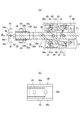
- FIG. 7A is a longitudinal sectional view of a main part along the line VII-VII in FIG. 6 showing the reinforcing film supply cassette, and FIG.
- FIG. 7B is a front view of the reinforcing film supply cassette viewed from the direction of arrow VII ′ in FIG. .
- FIG. 8 is a cross-sectional view of an essential part taken along line VIII-VIII in FIG. 7A showing a reinforcing film supply cassette. It is sectional drawing of the cassette support part in which the reinforcement film supply cassette was positioned.
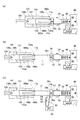
- (A) is a side view of the main part of the reinforcing film supply cassette showing a state in which the guide head is pressed by the gripper and retracted, and the tip of the reinforcing film tape held by the guide head protrudes from the slit of the guide head;
- Is a side view of the main part of the reinforcing film supply cassette showing a state in which the reinforcing film tape protruding from the slit of the guide head is gripped and pulled out by the gripper
- (c) is a cutting mechanism by which the reinforcing film tape pulled out by the gripper is cut.
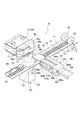
- a reinforcing film bonding apparatus 10 is an bonding apparatus that bonds a reinforcing film piece 16 to a space portion 12 of a fastener chain 11 to which a not-shown opening / closing insertion tool is attached. 20, a reinforcing film tape supply means 30, a cutting mechanism 90, a reinforcing film piece conveying means 100, and an ultrasonic welding device 120 as a reinforcing film piece adhering means.
- the fastener chain 11 conveyed by the fastener chain conveying means 20 has a fastener element row 15 in which elements 14 are provided along opposing tape side edges 13a of a pair of long fastener tapes 13, and has a predetermined interval. A space portion 12 from which the fastener element row 15 has been removed is formed.
- the upstream side is the front side in the transport direction and the downstream side is the rear side in the transport direction, according to the transport direction.
- the fastener chain conveying means 20 includes a driving roller 21 and a driven roller 22.
- the fastener chain 11 is sandwiched between the driving roller 21 and the driven roller 22, and the driving roller 21 is rotationally driven. Transport.
- the sensing means 24 is arranged above the fastener element row 15 on the upstream side in the conveying direction of the fastener chain 11 from the installation position of the ultrasonic welding device 120.
- the sensing means 24 detects the presence or absence of the element 14 when the sensing roller 25 rolls on the element 14 of the fastener chain 11 being conveyed. That is, when the space portion 12 of the fastener chain 11 to be conveyed reaches the position of the detection roller 25, the detection roller 25 enters the space portion 12, and the swing lever 26 to which the detection roller 25 is attached swings. Thus, the space portion 12 is detected.
- the fastener chain transporting unit 20 When the space part 12 is detected by the sensing means 24, the fastener chain transporting unit 20 further transports the fastener chain 11 by a predetermined distance, and the space part 12 overlaps the position of the ultrasonic welding device 120 in a top view. The conveyance of the fastener chain 11 is stopped. Then, as described later, after the bonding by the ultrasonic welding device 120 is completed, the conveyance by the fastener chain conveying means 20 is resumed, and the above operation is repeated to intermittently convey the fastener chain 11.
- the reinforcing film tape supply means 30 is disposed on the side in the width direction of the intermittently conveyed fastener chain 11, and removably supports the reinforcing film supply cassette 31 and the reinforcing film supply cassette 31. And a film cassette support means 32.
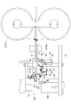
- the reinforcing film supply cassette 31 includes a tape reel support portion 34 that rotatably supports a pair of tape reels 33 around which the reinforcing film tape 17 is wound, and a tape reel support portion 34. And a guide rod (guide member) 35 that extends in the pull-out direction of the reinforcing film tape 17 orthogonal to the longitudinal direction of the tape reel support 34 and the pull-out direction of the reinforcing film tape 17 ( A guide head 36 disposed on the end side in the pull-out direction of the guide rod 35 so as to be relatively movable in the extending direction of the guide rod 35.
- the reinforcing film tape 17 is a film tape formed of a relatively low melting point synthetic resin such as nylon or polyester.
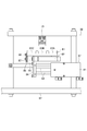
- the guide rod 35 includes a main body portion 37 formed in the shape of a long bar having a rectangular cross section and a guide head support portion 38 formed in a T-shaped plate shape.
- a leg portion 38a of the guide head support portion 38 is fitted into a vertical groove 37a (see FIG. 8) formed at the tip of the guide head 38 and fixed integrally with a pin 28.
- the guide head support portion 38 is fixed to the main body portion 37 so that the wide head portion 38f faces forward, and the leg portion is between the guide head support portion 38 and the main body portion 37 in plan view.
- a substantially U-shaped space S is provided on both the left and right sides of 38a (see FIGS. 6 and 8).
- a shallow groove 38b is formed at the center in the width direction of the upper and lower surfaces of the wide head 38f so that the reinforcing film tape 17 can be inserted, and covers the shallow groove 38b.
- the guide plate 39 is fixed to the upper and lower surfaces of the guide head support portion 38 by screws 40.
- a gap C is formed on the upper and lower surfaces of the guide head support portion 38, which is defined by the shallow grooves 38 b and the guide plate 39 and through which the reinforcing film tape 17 can be inserted.
- the chamfer 39a provided on the inner surface side rear edge of the guide plate 39 is for facilitating insertion of the reinforcing film tape 17.
- a pair of shafts 42 having one end fixed to the guide head 36 by a screw 41 are slidably fitted in a pair of fitting holes 38c formed in parallel to the guide head support portion 38. is doing.
- the other ends of the pair of shafts 42 protruding rearward from the pair of fitting holes 38c are disposed in a substantially U-shaped space S, and an annular groove 42a is formed in the middle portion of the pair of shafts 42.
- a coil spring 44 is disposed between the retaining ring 43 that engages with the annular groove 42 a and the front end surface of the main body portion 37, and the guide head 36 is always separated from the guide head support portion 38 by the elastic force of the coil spring 44. It is biased in the protruding direction (forward).
- a pair of upper and lower slits 45 are formed in parallel at positions corresponding to the shallow grooves 38b of the guide head support portion 38 (see FIG. 7B).
- the pair of slits 45 are cut out to the side surface in the width direction of the guide head 36, but may be open holes as long as the insertion of the reinforcing film tape 17 is allowed.
- a chamfer 36 a is applied to the edge in the vertical direction on the front end face side of the guide head 36. The chamfer 36a is for assisting the cutting function of the cutting mechanism 90, and will be described in detail later.
- a pair of fixing plates 46 are fixed to both side surfaces of the main body portion 37 by pins 28 and bolts 54 together with the leg portions 38 a of the guide head support portion 38.
- a locking projection 46 a that protrudes forward is provided at the vertical corner of the tip of the fixing plate 46.
- the locking projection 46a is formed symmetrically with respect to the vertical center line CL of the guide rod 35 (see FIG. 7A), and is used for positioning with respect to the film cassette support means 32 described in detail later.
- a braking member support portion 47 provided with a U-shaped groove 47a that opens forward in plan view is provided on the upper and lower surfaces of the main body portion 37.
- the plate 46 is clamped and fixed.
- a spring retainer plate 48 is fixed to the top and bottom surfaces of the brake member support 47 by a countersunk screw 49 so as to cover the U-shaped groove 47a.
- a braking member 51 is rotatably supported by a fulcrum pin 50.
- the spring hole 51b provided on the one end 51a side of the braking member 51 on the tip side from the fulcrum pin 50 is provided with a coil spring 52 between the spring pressing plate 48, and the one end 51a of the braking member 51 is always attached.
- the guide head support portion 38 is biased so as to contact the upper surface 38d and the lower surface 38e.
- each of the reinforcing film tapes 17 fed out from the pair of tape reels 33 is wound around a pair of guide rollers 53 disposed in an intermediate portion of the guide rod 35 and forward along the guide rod 35 (FIG. 5).
- the reinforcing film supply cassette 31 is configured by being inserted into the pair of slits 45 of the guide head 36.
- the reinforcing film tape 17 fed out from the tape reel 33 is biased so as to come into contact with the guide head support portion 38 by the elastic force of the coil spring 52.
- the upper surface 38d and the lower surface 38e of the guide head support portion 38 are inserted so that when the reinforcing film tape 17 moves in the drawing direction, one end 51a of the braking member 51 is centered on the fulcrum pin 50 as a guide head. It swings in a direction away from the support portion 38 and allows movement in the pull-out direction.
- the one end 51a of the braking member 51 swings in the direction of biting into the guide head support portion 38 around the fulcrum pin 50, and the reinforcing film tape 17 Is prevented from moving in the opposite direction.
- the reinforcing film supply cassette 31 includes a pair of tape reels 33, a pair of braking members 51, and a pair of slits 45 that are opposite to each other with respect to the guide rod 35. Then, the guide rod 35 is arranged symmetrically with respect to the vertical center line CL. Thereby, attachment to the film cassette support means 32 mentioned later is attained, without minding the up-down direction of the reinforcement film supply cassette 31.
- FIG. 5 the reinforcing film supply cassette 31 includes a pair of tape reels 33, a pair of braking members 51, and a pair of slits 45 that are opposite to each other with respect to the guide rod 35. Then, the guide rod 35 is arranged symmetrically with respect to the vertical center line CL. Thereby, attachment to the film cassette support means 32 mentioned later is attained, without minding the up-down direction of the reinforcement film supply cassette 31.
- the film cassette support means 32 includes a film cassette support base 61 that detachably supports the reinforcing film supply cassette 31, a support base drive means 62 that moves the film cassette support base 61, Is provided.
- the film cassette support base 61 includes a support table 74, a substantially L-shaped positioning piece 68, and a presser block 71, and in other words, a direction in which the fastener chain 11 is conveyed, in other words, reinforcement It has three cassette support grooves 63 (63A, 63B, 63C) arranged in a horizontal direction orthogonal to the drawing direction of the film tape 17.
- the positioning piece 68 is fixed to the front end of the support table 74 with a screw 69
- the block 71 is fixed to the rear end of the support table 74 with a screw 70.
- the reinforcing film supply cassette 31 is mounted and supported in each cassette support groove 63.
- a slider 65 constituting a linear guide 64 is fixed to the lower surface of the film cassette support 61.
- the guide rail 66 of the linear guide 64 on which the slider 65 is slidably laid is fixed to the base 67 along the conveying direction of the fastener chain 11.
- the film cassette support base 61 is movable in the transport direction of the fastener chain 11 together with the reinforcing film supply cassette 31 supported by the cassette support groove 63.
- the reinforcing film supply cassette 31 engages the locking protrusion 46 a of the fixing plate 46 with a groove 72 formed by a substantially L-shaped positioning piece 68 and a film cassette support base 61. Then, the rear portion of the fixing plate 46 is lowered so that the groove 72 and the holding block 71 are positioned and fixed to the cassette support groove 63 by one touch.
- sensors 73 arranged in a fixed manner with respect to the base 67 are provided in front of the film cassette support 61 and above and below the reinforcing film supply cassette 31 positioned on the film cassette support 61, respectively. The presence / absence of the reinforcing film tape 17 supplied from the reinforcing film supply cassette 31 is detected.
- the support table driving means 62 is for moving the film cassette support table 61 along the conveyance direction of the fastener chain 11 and includes a first cylinder 81 and a second cylinder 82.
- the first cylinder 81 is provided such that the piston rod 83 expands and contracts along the conveying direction of the fastener chain 11.
- the second cylinder 82 is fixed to the movable plate 84 fixed to the piston rod 83 of the first cylinder 81, and drives the piston rod 85 in the conveying direction of the fastener chain 11.
- a pair of connecting plates 86 are fixed to the piston rod 85 of the second cylinder 82 via spacers 87.
- a coupling plate 88 fixed to the side surface of the film cassette support base 61 is fitted between the pair of coupling plates 86.
- the film cassette support 61 is driven by the first and second cylinders 81 and 82 and is movable in the conveying direction of the fastener chain 11, and the cassette support groove in which the desired reinforcing film supply cassette 31 is mounted.
- 63 is positioned at a position corresponding to a cutting mechanism 90 described later.
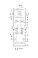
- the cutting mechanism 90 includes a moving blade 91 that is disposed in the lower front portion of the guide head 36 and is driven in the vertical direction by a driving device 92 such as a cylinder.
- the movable blade 91 is urged clockwise around the support pin 93 in FIG. 2 by an elastic member 94 (see FIG. 10C) such as a spring.
- an elastic member 94 such as a spring.
- the front end surface 36 b of the guide head 36 functions as a tool post, and a pair of reinforcing film tapes 17 drawn out from a pair of slits 45 of the guide head 36 by a gripper 101 described later cooperate with the movable blade 91.
- the reinforcing film piece 16 is formed by cutting.
- the chamfer 36a provided on the upper and lower edges of the front end surface 36b of the guide head 36 guides the movable blade 91 so that the movable blade 91 slides along the front end surface 36b. Further, when the movable blade 91 moves upward on the front end surface 36 b of the guide head 36, it is pushed between the movable blade 91 and the front end surface 36 b in the pulling-out direction of the reinforcing film tape 17 by the elastic force of the coil spring 44. The pressure is acting, and the reinforcing film tape 17 can be cut accurately.
- the length of the reinforcing film piece 16 cut by the cutting mechanism 90 is set to be slightly shorter than the width of the fastener chain 11.
- the reinforcing film piece conveying means 100 includes a gripper 101 that grips the pair of reinforcing film tapes 17 or the pair of reinforcing film pieces 16, the gripper 101 in the pulling direction of the reinforcing film tape 17, and Gripper driving means 102 that moves along the conveying direction of the fastener chain 11.
- the gripper 101 has a fixed jaw 103 formed in a bifurcated shape having a groove 103 a capable of accommodating the fastener chain 11 at the tip portion, and a pair of movable jaws 104 a and 104 b disposed above and below the fixed jaw 103. Is provided.
- the movable jaws 104a and 104b are swingably supported by a holder 109 described later by a shaft 105 provided at an intermediate portion in the longitudinal direction.
- the movable jaws 104a and 104b are urged by a spring (not shown) so that the distal ends thereof are separated from the distal ends of the fixed jaws 103.
- a pair of openings 106 a and 106 b formed such that the distal end of the fixed jaw 103 and the distal ends of the movable jaws 104 a and 104 b are spaced apart from each other are at positions facing the pair of slits 45 of the guide head 36.
- the leading ends of the pair of guided reinforcing film tapes 17 are inserted and held in the corresponding openings 106a and 106b.
- a cam portion 108a formed at the front end of the piston 108 is disposed in a gap 107 formed between the rear ends of the pair of movable jaws 104a and 104b.
- the piston 108 is urged away from the gap 107 by another spring (not shown).
- the cam portion 108a of the piston 108 is separated from the gap 107 by the elastic force of this spring, the movable jaw 104a, The front end of 104b is separated from the front end of the fixed jaw 103, and the openings 106a and 106b are opened.
- the gripper driving means 102 is for moving the gripper 101 along the pull-out direction of the reinforcing film tape 17 and the conveying direction of the fastener chain 11, and is opposite to the reinforcing film tape supply means 30 with respect to the fastener chain 11. It is arranged.
- the gripper driving means 102 moves the gripper 101 along the direction perpendicular to the conveying direction of the fastener chain 11 (the pulling-out direction of the reinforcing film tape 17) by the servo motor 118 attached to the moving table 112, and moves by the cylinder device 111.
- the gripper 101 is moved along the conveyance direction of the fastener chain 11 by moving the base 112 along the conveyance direction of the fastener chain 11.
- a pair of guide rods 115 (only one is shown in FIG. 4) are fixed between the front wall 113 and the rear wall 114 of the moving base 112 along the pulling direction of the reinforcing film tape 17.
- a holder 109 that holds the gripper 101 is slidably fitted to the pair of guide rods 115.
- a screw shaft 116 that constitutes a ball screw mechanism together with a ball nut 117 to be screwed is rotatably disposed on the front wall 113 and the rear wall 114 of the moving base 112, a screw shaft 116 that constitutes a ball screw mechanism together with a ball nut 117 to be screwed is rotatably disposed on the front wall 113 and the rear wall 114 of the moving base 112, a screw shaft 116 that constitutes a ball screw mechanism together with a ball nut 117 to be screwed is rotatably disposed.
- the screw shaft 116 is rotationally driven by a servo motor 118 fixed to the rear wall 114.
- the screw shaft 116 is rotated by the drive of the servo motor 118, the holder 109 connected to the ball nut 117 is guided by the pair of screw shafts 116 and together with the gripper 101 in a direction perpendicular to the conveying direction of the fastener chain 11. Moving.
- the gripper 101 driven by the servo motor 118 can be stopped at a plurality of arbitrary positions along the direction orthogonal to the conveying direction of the fastener chain 11. For example, a gripping position where the gripper 101 grips the ends of the pair of reinforcing film tapes 17 guided by the slits 45, a cutting position where the pair of reinforcing film tapes 17 are pulled out by a predetermined length, and a pair of reinforcing film pieces 16 are gripped. It is possible to stop at a standby position where it waits.
- the gripper 101 that pulls out the reinforcing film tape 17 is moved by a ball screw mechanism driven by a servo motor 118, the length of the reinforcing film piece 16 is easily set to an arbitrary length according to the fastener chain 11. can do.
- the cylinder device 111 has a piston rod 119, one end of which is fixed to the moving table 112, arranged along the conveying direction of the fastener chain 11, and the cylinder device 111 is operated to expand and contract the piston rod 119.
- the fastener chain 11 is reciprocated along the conveying direction. For example, it can be stopped at a standby position where the pair of reinforcing film pieces 16 are held and waited, and at a welding position where the reinforcing film pieces 16 are welded to the space portion 12 of the fastener chain 11.
- the ultrasonic welding device 120 is disposed at a position where the pair of reinforcing film tapes 17 drawn out from the pair of slits 45 of the guide head 36 intersect the fastener chain 11 in a top view.
- the ultrasonic welding apparatus 120 includes an ultrasonic horn 121 disposed above the intermittently conveyed fastener chain 11 and an anvil 122 disposed below the fastener chain 11 so as to face the ultrasonic horn 121.
- the reinforcing film bonding apparatus 10 configured as described above will be described.
- the reinforcing film tape 17 fed out from the pair of tape reels 33 is wound around the pair of guide rollers 53 and led forward along the guide rod 35.
- a pair of slits 45 of the guide head 36 is obtained. It is assumed that it is inserted and set.
- the locking projection 46a of the fixing plate 46 is inserted in a state where the rear portion of the fixing plate 46 is lifted so as to engage with the groove 72 of the film cassette support base 61.
- the reinforcing film supply cassette 31 is mounted in the cassette support groove 63 by bringing the lower surface of the fixing plate 46 into contact with the support table 74.
- the reinforcing film supply cassette 31 can be attached to and detached from the film cassette support base 61 with a single touch.
- the reinforcing film supply cassette 31 mounted in each cassette support groove 63 may be one in which the reinforcing film tape 17 having a different width is wound, or may be one in which the reinforcing film tape 17 having the same width is wound. It is decided arbitrarily according to the contents.
- the gripper 101 in which the tips of the movable jaws 104a and 104b are spaced apart from the tips of the fixed jaw 103 and the openings 106a and 106b are opened is connected to a ball screw mechanism (ball nut).
- the screw shaft 116) is driven toward the guide head 36, the tip of the fixed jaw 103 is brought into contact with the front end surface 36b of the guide head 36, and the guide head 36 is reinforced with the reinforcing film tape against the elastic force of the coil spring 44. 17 is moved in the direction opposite to the pulling direction.
- the reinforcing film tape 17 whose movement in the direction opposite to the pulling direction of the reinforcing film tape 17 is prevented by the braking member 51 has the tip 17a protruding from the slit 45 by the length of the retraction of the guide head 36, and the gripper 101 Are inserted into the openings 106a and 106b.
- the cam portion 108a of the piston 108 enters the gap 107 of the gripper 101 to close the openings 106a and 106b, and a pair of reinforcing film tapes are formed by the fixed jaw 103 and the movable jaws 104a and 104b.
- the gripper 101 is retracted by a predetermined distance, for example, a distance slightly shorter than the width of the fastener chain 11, and the pair of reinforcing film tapes 17 are pulled out from the slit 45 of the guide head 36.
- the reinforcing film tape 17 is pulled out by the gripper 101 at the tip 17a and pulled out, so that the reinforcing film tape 17 can be pulled out stably without being bent or bent in the middle.
- the pair of reinforcing film tapes 17 held by the gripper 101 are moved up by the driving device 92 of the cutting mechanism 90 along the front end surface 36 b of the guide head 36. Are cut in cooperation with the front end surface 36b of the guide head 36 that functions as a tool post, and a pair of reinforcing film pieces 16 are formed.
- the fastener chain 11 conveyed by the fastener chain conveying means 20 is configured such that when the space portion 12 reaches the position of the detection roller 25, the detection roller 25 is detached from the element 14 and enters the space portion 12, whereby the swing lever 26. Oscillates and the space portion 12 is detected, and is further conveyed and stopped until the space portion 12 is positioned between the ultrasonic horn 121 and the anvil 122 of the ultrasonic welding device 120.
- the servo motor 118 of the gripper driving means 102 is actuated so that the pair of reinforcing film pieces 16 gripped by the gripper 101 are placed between the ultrasonic horn 121 and the anvil 122 with the upper and lower surfaces of the fastener chain 11 facing each other.
- the ultrasonic welding device 120 sandwiches the pair of reinforcing film pieces 16 together with the fastener chain 11 and ultrasonically welds them to the upper and lower surfaces of the fastener chain 11. Thereafter, the same operation is repeated, and the reinforcing film piece 16 is continuously welded to the space portion 12 of the fastener chain 11.
- the tape reel support portion 34 that supports the tape reel 33, the guide rod 35 that guides the reinforcing film tape 17, and the guide rod 35 abut.
- the reinforcing film tape 17 is inserted between the end 51a biased in this way and the guide rod 35, and the braking member that allows the reinforcing film tape 17 to move in the pull-out direction and prevents the movement in the reverse direction.
- the gripper 101 pulls the guide head 36 out of the reinforcing film tape 17.
- the tip end 17a of the reinforcing film tapes 17 is protruded from the slit 45 can be pulled out by grasping gripper 101, the reinforcement film tape 17 can be accurately supplied.
- the reinforcing film supply cassette 31 can be replaced, thereby reducing the work time at the time of replacement. The operating rate of the reinforcing film bonding apparatus 10 can be improved.
- the guide rod 35 includes a pair of tape reels 33, a pair of braking members 51, and a pair of slits 45 that are arranged symmetrically with respect to the vertical center line CL of the guide rod 35.
- a fixing plate 46 that is formed symmetrically with respect to the vertical center line CL and has a pair of locking projections 46 a for engaging with the grooves 72 of the film cassette support base 61 that supports the reinforcing film supply cassette 31.
- the reinforcing film supply cassette 31 can be attached to the film cassette support base 61 without worrying about the vertical direction, the working time is shortened.
- the front end surface 36b of the guide head 36 has a chamfer 36a at an edge in the vertical direction and constitutes a tool post for cutting the reinforcing film tape 17 in cooperation with the movable blade 91 that moves in the vertical direction.
- the film tape 17 can be cut securely and cleanly.
- the reinforcing film piece including the fastener chain conveying means 20, the reinforcing film tape supplying means 30, the cutting mechanism 90 of the reinforcing film tape 17, the gripper 101 and the gripper driving means.
- Conveying means 100 and reinforcing film piece adhering means 120 are provided.
- the reinforcing film tape supply means 30 includes the reinforcing film supply cassette 31 and the film cassette support means 32 that detachably supports the reinforcing film supply cassette 31, so that the reinforcing film tape 17 of the tape reel 33 is emptied.
- the reinforcing film supply cassette 31 can be replaced, and the working time at the time of replacement can be shortened and the operating rate of the reinforcing film bonding apparatus 10 can be improved.
- the film cassette support means 32 includes a film cassette support base 61 provided with a plurality of cassette support grooves 63 and a support base drive means 62 that moves the film cassette support base 61, the support base drive means 62.
- the support base drive means 62 By moving the film cassette support base 61, an arbitrary reinforcing film supply cassette 31 can be selected from the plurality of reinforcing film supply cassettes 31 mounted in the cassette support groove 63 and easily exchanged.
- the reinforcing film pieces 16 are bonded to the upper and lower surfaces of the fastener chain 11, but the present invention is not limited to both surfaces, and may be bonded to only one surface.
- the tape reel 33, the braking member 51, and the slit 45 are described as being disposed one by one on the opposite side with respect to the guide rod 35, but are disposed one by one. It may be a thing.
- the reinforcing film adhering means is not limited to the ultrasonic welding apparatus of the above embodiment, and may be any means as long as it adheres the reinforcing film piece to the space portion of the fastener chain, such as a high frequency welding apparatus or a heater. It can also be set as a heat welding apparatus.
- the reinforcing film bonding apparatus of the present embodiment is configured to replace every reinforcing film supply cassette, but the reinforcing film bonding apparatus of the present invention can also be applied to a mechanism for replacing only a tape reel. That is, the reinforcing film tape supply means of the reinforcing film bonding apparatus of the present invention is not limited to the reinforcing film cassette, and the tape reel support portion 34 that rotatably supports the tape reel 33 around which the reinforcing film tape 17 is wound.
- the guide member 35 that extends from the tape reel support 34 in the pulling-out direction of the reinforcing film tape 17 and guides the reinforcing film tape 17 is urged so that the one end 51 a abuts against the guiding member 35,
- the reinforcing film tape 17 that allows the reinforcing film tape 17 inserted between the one end 51 a to move in the pull-out direction and prevents movement in the direction opposite to the pull-out direction and the guide member 35.
- the reinforcing film tape 1 is disposed on the end side in the pulling direction of the guide member 35 so as to be relatively movable in the pulling direction.
- a guide head 36 with a slit 45 for inserting an elastic member 44 for urging the guide head 36 in the drawing direction of the reinforcing film tapes 17 with respect to the guide member 35 may be a configuration including. Thereby, the front end of the reinforcing film tape 17 can be gripped by the gripper 101 and the reinforcing film tape 17 can be pulled out straight, and the reinforcing film tape 17 can be supplied with high accuracy.
Landscapes
- Replacement Of Web Rolls (AREA)
Abstract
La présente invention concerne une cassette d'alimentation (31) en film de renforcement, comprenant : un support (34) de bobine à ruban qui supporte une bobine (33) à ruban ; une barre de guidage (35) qui guide le ruban (17) de film de renforcement ; un élément de freinage (51) qui permet au ruban (17) de film de renforcement de se déplacer dans la direction dans laquelle il est tiré et qui empêche un déplacement dans la direction opposée ; une tête de guidage (36) qui présente une fente (45) par l'intermédiaire de laquelle le ruban (17) de film de renforcement est inséré et qui est disposée de façon à pouvoir de déplacer relativement à la barre de guidage (35) ; et un élément élastique (44) qui sollicite la tête de guidage (36) dans la direction dans laquelle le ruban (17) de film de renforcement doit être tiré.
Priority Applications (3)
| Application Number | Priority Date | Filing Date | Title |
|---|---|---|---|
| CN201380044339.5A CN104582522B (zh) | 2013-08-07 | 2013-08-07 | 补强膜供给匣以及补强膜粘接装置 |
| PCT/JP2013/071422 WO2015019453A1 (fr) | 2013-08-07 | 2013-08-07 | Cassette d'alimentation en film de renforcement et dispositif de fixation de film de renforcement |
| TW103125425A TWI505790B (zh) | 2013-08-07 | 2014-07-25 | 補強膜供給匣以及補強膜接著裝置 |
Applications Claiming Priority (1)
| Application Number | Priority Date | Filing Date | Title |
|---|---|---|---|
| PCT/JP2013/071422 WO2015019453A1 (fr) | 2013-08-07 | 2013-08-07 | Cassette d'alimentation en film de renforcement et dispositif de fixation de film de renforcement |
Publications (1)
| Publication Number | Publication Date |
|---|---|
| WO2015019453A1 true WO2015019453A1 (fr) | 2015-02-12 |
Family
ID=52460821
Family Applications (1)
| Application Number | Title | Priority Date | Filing Date |
|---|---|---|---|
| PCT/JP2013/071422 Ceased WO2015019453A1 (fr) | 2013-08-07 | 2013-08-07 | Cassette d'alimentation en film de renforcement et dispositif de fixation de film de renforcement |
Country Status (3)
| Country | Link |
|---|---|
| CN (1) | CN104582522B (fr) |
| TW (1) | TWI505790B (fr) |
| WO (1) | WO2015019453A1 (fr) |
Cited By (1)
| Publication number | Priority date | Publication date | Assignee | Title |
|---|---|---|---|---|
| WO2022208979A1 (fr) * | 2021-03-30 | 2022-10-06 | Ykk株式会社 | Bande adhésive de fixation |
Families Citing this family (4)
| Publication number | Priority date | Publication date | Assignee | Title |
|---|---|---|---|---|
| CN105904637B (zh) * | 2015-11-30 | 2018-07-24 | 浙江隐齿丽医学技术有限公司 | 压膜系统 |
| CN108464584B (zh) * | 2017-02-23 | 2021-01-12 | Ykk株式会社 | 拉链牙链带搬送用引导装置 |
| CN108652144B (zh) * | 2017-03-29 | 2020-11-10 | Ykk株式会社 | 拉链条制造装置及方法、以及对拉链条贴附增强膜的方法 |
| CN116784576B (zh) * | 2022-03-14 | 2026-02-13 | Ykk株式会社 | 拉头穿通机构 |
Citations (3)
| Publication number | Priority date | Publication date | Assignee | Title |
|---|---|---|---|---|
| JPS58188249A (ja) * | 1982-04-28 | 1983-11-02 | Yoshida Kogyo Kk <Ykk> | テ−プ状物の間欠送り装置 |
| JPH06144689A (ja) * | 1992-11-06 | 1994-05-24 | Yoshida Kogyo Kk <Ykk> | テープカセット及び熱溶着性テープ片の自動貼着装置 |
| JPH07237799A (ja) * | 1994-02-25 | 1995-09-12 | N C Ee:Kk | シート状物引出し装置のクランプ機構 |
Family Cites Families (2)
| Publication number | Priority date | Publication date | Assignee | Title |
|---|---|---|---|---|
| JP3763743B2 (ja) * | 2001-01-31 | 2006-04-05 | Ykk株式会社 | スライドファスナーの製造方法 |
| JP3812652B2 (ja) * | 2001-12-28 | 2006-08-23 | Ykk株式会社 | ファスナーテープに対する補強テープ片の超音波溶着方法及び溶着装置 |
-
2013
- 2013-08-07 CN CN201380044339.5A patent/CN104582522B/zh active Active
- 2013-08-07 WO PCT/JP2013/071422 patent/WO2015019453A1/fr not_active Ceased
-
2014
- 2014-07-25 TW TW103125425A patent/TWI505790B/zh active
Patent Citations (3)
| Publication number | Priority date | Publication date | Assignee | Title |
|---|---|---|---|---|
| JPS58188249A (ja) * | 1982-04-28 | 1983-11-02 | Yoshida Kogyo Kk <Ykk> | テ−プ状物の間欠送り装置 |
| JPH06144689A (ja) * | 1992-11-06 | 1994-05-24 | Yoshida Kogyo Kk <Ykk> | テープカセット及び熱溶着性テープ片の自動貼着装置 |
| JPH07237799A (ja) * | 1994-02-25 | 1995-09-12 | N C Ee:Kk | シート状物引出し装置のクランプ機構 |
Cited By (1)
| Publication number | Priority date | Publication date | Assignee | Title |
|---|---|---|---|---|
| WO2022208979A1 (fr) * | 2021-03-30 | 2022-10-06 | Ykk株式会社 | Bande adhésive de fixation |
Also Published As
| Publication number | Publication date |
|---|---|
| CN104582522B (zh) | 2017-03-15 |
| TW201505578A (zh) | 2015-02-16 |
| TWI505790B (zh) | 2015-11-01 |
| CN104582522A (zh) | 2015-04-29 |
Similar Documents
| Publication | Publication Date | Title |
|---|---|---|
| WO2015019453A1 (fr) | Cassette d'alimentation en film de renforcement et dispositif de fixation de film de renforcement | |
| WO2015136732A1 (fr) | Dispositif et procédé de coupe | |
| CN101223093A (zh) | 用于拼接标签带的装置和方法 | |
| JP6074622B2 (ja) | スプライシング装置及びスプライシング装置における部品テープの送り方法 | |
| TWI527533B (zh) | A reinforcing film followed by a device and a reinforcing film followed by a method | |
| JP6259986B2 (ja) | スプライシング装置 | |
| TWI546029B (zh) | 增強膜黏著裝置及具有可分離式嵌插件的拉鏈 | |
| CN104968233A (zh) | 反开式拉链的制造方法及制造装置 | |
| CN104507348B (zh) | 增强膜粘着装置 | |
| CN109463851B (zh) | 连续拉链牙链链带加工机 | |
| TWM536488U (zh) | 增強膜黏著裝置 | |
| CN104797157B (zh) | 增强膜粘着装置 | |
| CN111084469B (zh) | 增强膜粘接装置 | |
| WO2015136610A1 (fr) | Dispositif de montage de sections d'arrêt | |
| TWI519252B (zh) | 補強膜黏著裝置及其黏著方法 | |
| CN109549296B (zh) | 拉链的最终加工机用的支架、拉链的最终加工机 | |
| CN113942861A (zh) | 加强膜带供给装置 | |
| JP5126951B2 (ja) | 包装フィルム切断装置 | |
| CN121020293B (zh) | 一种带状物拼接设备 | |
| JP2016020234A (ja) | 連続帯状体の繋ぎ装置 | |
| JP4846859B2 (ja) | チャック付き袋体の製造方法及びその装置 | |
| JP5729402B2 (ja) | 包装紙接続装置、包装紙接続方法、及び、包装装置 | |
| CN119348968A (zh) | 一种电磁铁控制机器人剪空纸箱捆扎带系统及其控制方法 | |
| KR200386166Y1 (ko) | 슬라이드 파스너 보강 필름 부착장치 | |
| JPH1143112A (ja) | 自動テープ接合装置 |
Legal Events
| Date | Code | Title | Description |
|---|---|---|---|
| 121 | Ep: the epo has been informed by wipo that ep was designated in this application |
Ref document number: 13890920 Country of ref document: EP Kind code of ref document: A1 |
|
| NENP | Non-entry into the national phase |
Ref country code: DE |
|
| 122 | Ep: pct application non-entry in european phase |
Ref document number: 13890920 Country of ref document: EP Kind code of ref document: A1 |
|
| NENP | Non-entry into the national phase |
Ref country code: JP |