WO2015019475A1 - Distributeur automatique la présente invention concerne un distributeur automatique équipé d'une porte intérieure correspondant à un compartiment d'échantillons de produit formé dans une porte extérieure. - Google Patents
Distributeur automatique la présente invention concerne un distributeur automatique équipé d'une porte intérieure correspondant à un compartiment d'échantillons de produit formé dans une porte extérieure. Download PDFInfo
- Publication number
- WO2015019475A1 WO2015019475A1 PCT/JP2013/071563 JP2013071563W WO2015019475A1 WO 2015019475 A1 WO2015019475 A1 WO 2015019475A1 JP 2013071563 W JP2013071563 W JP 2013071563W WO 2015019475 A1 WO2015019475 A1 WO 2015019475A1
- Authority
- WO
- WIPO (PCT)
- Prior art keywords
- product sample
- mounting plate
- insulating material
- heat insulating
- vending machine
- Prior art date
- Legal status (The legal status is an assumption and is not a legal conclusion. Google has not performed a legal analysis and makes no representation as to the accuracy of the status listed.)
- Ceased
Links
Images


Classifications
-
- G—PHYSICS
- G07—CHECKING-DEVICES
- G07F—COIN-FREED OR LIKE APPARATUS
- G07F9/00—Details other than those peculiar to special kinds or types of apparatus
- G07F9/10—Casings or parts thereof, e.g. with means for heating or cooling
Definitions
- the present invention relates to a vending machine provided with an inner door corresponding to a product sample chamber configured in an outer door.
- a product sample chamber is formed above the outer door that closes the front surface of the main body, and samples of products to be sold are displayed in the product sample chamber.
- an upper inner door for closing the product storage portion in the main body is provided, and the upper inner door can be opened and closed integrally with the outer door.
- this upper side inner door constitutes the back of the product sample chamber, and is provided on the rear side of the product sample mounting plate in which members such as a product sample holder and a lighting device for holding the product sample are attached to the front surface. It is composed of heat insulating material. And it was made possible to open and close backward independently of the outer door in the state where the outer door was opened, and the product sample could be exchanged in the state opened rearward from the outer door (for example, see Patent Document 1). )
- the product sample mounting plate is made of a coated steel plate made of a thin sheet metal, and a simple plate-like heat insulating material such as foamed polyurethane has been used as the heat insulating material.
- a structure for attaching a member such as a product sample holder or a lighting device (a special fixture such as a product sample holder and an integrally formed nail or screw) escapes.
- a lighting device a special fixture such as a product sample holder and an integrally formed nail or screw
- the present invention has been made in order to solve the conventional technical problem, and it is possible to reduce the cost by simplifying the structure while maintaining or improving the heat insulating performance of the inner door.
- the object is to provide a vending machine with improved stability.
- the vending machine of the present invention includes an outer door that closes the front opening of the main body so as to be freely opened and closed, a product sample chamber configured in the outer door, and a product storage configured in the main body. And a product sample mounting plate that is provided corresponding to the product sample chamber and that closes the front opening of the product storage portion so that it can be opened and closed. And a heat insulating material provided on the rear side of the product sample mounting plate with a space therebetween, and a protrusion that partially contacts the rear surface of the product sample mounting plate on the front surface of the heat insulating material. It is formed integrally.
- the vending machine according to a second aspect of the present invention is characterized in that, in the above invention, the front end of the protrusion is in line contact or point contact with the rear surface of the product sample mounting plate.
- the vending machine of the invention of claim 3 is characterized in that no protrusion is formed in a portion corresponding to a range in which the member is assumed to be attached to the front surface of the product sample mounting plate in each of the above inventions. .
- the vending machine of the invention of claim 4 causes the condensed water that grows on the rear surface of the product sample mounting plate to flow down on the front surface of the heat insulating material in each of the above inventions, with a space behind the product sample mounting plate.
- the drainage groove is integrally formed over the top and bottom.
- the vending machine of the invention of claim 5 is characterized in that, in the above invention, the front surface of the heat insulating material including the drainage groove is provided with open-cell packing that abuts against the rear surface of the product sample mounting plate. It is characterized by.
- a wiring storage portion for storing wiring is integrally formed on the front surface of the heat insulating material with a space behind the product sample mounting plate. It is characterized by.
- the vending machine of the invention of claim 7 includes an inner door mounting plate for mounting the product sample mounting plate on the heat insulating material in addition to the above, or in addition to the inner door mounting plate for mounting the inner door on the outer door.
- the board is embedded in the heat insulating material by insert molding.
- the vending machine of the invention of claim 8 is provided with a cover provided on the lower side of the heat insulating material in the above invention and formed with a drain receiver for receiving dew condensation water from the product sample mounting plate. It is attached to a board.
- a vending machine including an inner door that freely closes and opens the front opening of the product storage unit, the inner door includes a product sample mounting plate that constitutes a rear surface of the product sample chamber, and the product sample mounting plate And a heat insulating material provided at a distance on the rear side, and a protrusion partly contacting the rear surface of the product sample mounting plate is integrally formed on the front surface of the heat insulating material.
- the product sample mounting plate which is usually composed of a thin sheet metal, can be supported later by the protruding portion of the heat insulating material, and the structural stability of the inner door can be improved.
- the drainage groove for flowing down the condensed water that grows on the rear surface of the product sample mounting plate is provided above and below the front surface of the heat insulating material with a space behind the product sample mounting plate. If the molding is integrally performed, the condensed water generated on the rear surface of the product sample mounting plate can be smoothly discharged by the drainage groove. Also in this case, since the drainage groove is formed integrally with the heat insulating material, the drainage structure is simplified, and the cost can be reduced by reducing the number of parts.
- the open-cell packing that contacts the rear surface of the product sample mounting plate is provided on the front side of the heat insulating material including the drainage groove as in the invention of claim 5, it grows at a position away from the drainage groove. Condensed water is absorbed by the packing and can be discharged by being evaporated or guided to the drain.
- packing is provided on the left and right sides, and the space between the heat insulating material and the product sample mounting plate is divided vertically, so air flowing in from the bottom within the space and air in the vertical direction within the space Convection is prevented, and this also improves the heat insulation performance.
- the wiring storage part for storing wiring is integrally formed in the front surface of the heat insulating material on the front side of the product sample mounting plate as in the invention of the sixth aspect,
- the wiring drawn out or toward the product sample mounting plate can be stored in the wiring storage section. Thereby, it becomes unnecessary to attach a special wiring storage tool, and the number of parts can be simplified.
- FIG. 1 shows a front view of the vending machine 1 of the embodiment
- FIG. 2 shows a perspective view of the vending machine 1 with the outer door 3 opened.
- the vending machine 1 according to the embodiment includes a heat-insulating main body 2 having an open front surface, and one side (in the embodiment, the left side) is freely rotatable with respect to the main body 2 so as to close the front surface of the main body 2 so that it can be opened and closed
- a pivoted outer door 3 is provided.
- a product sample chamber 4 is formed in the upper front portion of the outer door 3, and a plurality of product selection switches corresponding to a plurality of product samples (samples of products to be sold) displayed in the product sample chamber 4. 6 is arranged.
- An advertisement panel (advertisement display unit) 5 is formed on the front surface of the outer door 3 below the product sample chamber 4, and a product outlet 7 is disposed on the lower front surface of the outer door 3 below the advertisement panel 5. Is configured.
- a decorative panel 8 is attached to the right side (non-pivot side) center of the front surface of the outer door 3, and a coin insertion slot 9 and a return lever 11 are provided in the decorative panel 8. Yes.
- a money amount indicator 12 is attached to the front surface of the left outer door 3 facing the decorative panel 8.
- a bill recognition device (bill burr) 14 is attached to the front surface of the lower door 3 on the lower side of the money amount indicator 12, and a coin return port 13 is disposed on the front surface of the right outer door 3 toward the product outlet 7. It is configured.
- the inside of the main body 2 includes a product storage section 16 whose upper, lower, left, and right and rear surfaces are surrounded by heat insulating walls, and the front surface is open.
- the product storage section 16 is partitioned in the left-right direction by a heat insulating partition plate 17. It has been.
- a plurality of serpentine-type product storage columns 18 in which products to be sold are stored in a meandering product passage are provided in the product storage section 16 partitioned by the partition plate 17 in the front-rear direction and the left-right direction.
- the front side of the product storage unit 16 has heat insulation, and an upper inner door 21 (inner door of the present invention) for opening and closing the upper side of the front opening of the product storage unit 16, and the product storage unit 16
- a lower side inner door 22 for opening and closing the lower side of the front opening is provided.
- the lower inner door 22 is pivotally supported by the main body 2.
- a product outlet 23 that communicates the product storage unit 16 side and the outer door 3 side is provided side by side in the left-right direction.
- An openable / closable unloading door 24 is attached to each commodity unloading port 23 so as to be pivotable about the upper edge.
- the commodity unloading port 23 is opened by being pushed by the commodity guided forward to open the commodity. Is taken out to the product outlet 7.
- a drain receiver 26 that receives dew condensation water generated in the product storage unit 16 is provided at the front lower portion of the product storage unit 16.
- the upper inner door 21 as the inner door of the present invention is attached to the outer door 3 corresponding to the rear side of the product sample chamber 4 of the outer door 3, and by opening and closing the outer door 3, The upper side of the front opening of the product storage unit 16 is opened and closed by the upper side inner door 21. Further, the upper inner door 21 can be opened and closed rearward independently of the outer door 3 with the outer door 3 open, and the upper inner door 21 can be opened rearward from the outer door 3 The product sample displayed in the sample chamber 4 can be exchanged.
- the upper-side inner door 21 of the embodiment is provided on the lower side of the heat insulating material 32, the product sample mounting plate 31 that is the back surface of the product sample chamber 4, the heat insulating material 32 that is provided behind the product sample mounting plate 31. Cover 33 and the like.
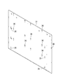
- the product sample mounting plate 31 is a back surface of the product sample chamber 4 in a state where the upper side inner door 21 is closed to the rear side of the outer door 3, and is made of a thin sheet metal coated steel plate as shown in FIG. It is comprised from the rectangular-shaped flat plate which consists of.
- a plurality of attachment holes 36 for attaching the LED illumination device 34 for illuminating the product sample and a bracket 40 of the product sample holder 50 for holding the product sample are attached to the product sample mounting plate 31.
- a plurality of mounting holes 35, a through hole 38 through which a hook 37 engaging with the outer door 3 passes, and the like are formed.
- the product sample holder 50 and the LED lighting device 34 correspond to members attached to the front surface of the product sample mounting plate 31 in the present invention.
- the product sample holder 50 according to the embodiment includes the left and right brackets 40 and a product sample shelf 45 attached between them (FIG. 7).
- the product sample holder 50 and the LED lighting device 34 are provided in a plurality of stages on the front surface of the product sample mounting plate 31. Note that the positions of the product sample holder 50 and the LED lighting device 34 differ depending on the size of the product sample to be displayed, and the positions of the mounting holes 35 and 36 differ depending on the products to be sold.
- a mounting claw (mounting structure) 39 protrudes from the rear end of the bracket 40 of the product sample holder 50, and this mounting claw 39 engages with the mounting hole 35 from the front side, thereby The holder 50 is attached to the front surface of the product sample mounting plate 31. Therefore, the mounting claw 39 protrudes to the rear side of the product sample mounting plate 31. Since the LED illumination device 34 is located between the brackets 40 and is attached to the attachment hole 36 with the same attachment structure, the LED illumination device 34 similarly protrudes to the rear side of the product sample attachment plate 31.
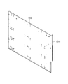
- the heat insulating material 32 is a molded heat insulating material made of polystyrene foam in the embodiment, and has substantially the same width dimension as that of the product sample mounting plate 31, a vertical dimension smaller than that, and a necessary heat insulating thickness.
- the polystyrene foam of an Example is easy to shape
- the upper side inner door 21 maintains sufficient heat insulating performance due to the characteristics described later.
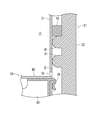
- each protrusion 41 of the embodiment extends in a streak shape from side to side, and the longitudinal section thereof is a semicircular shape as shown in FIG. 7 in the embodiment.
- the positions of the mounting holes 35 and 36 of the product sample mounting plate 31 for mounting the product sample holder 50 and the LED lighting device 34 differ depending on the products to be sold (the dimensions of the product samples to be displayed). Therefore, the protrusion 41 is formed in a portion corresponding to a range in which the mounting holes 35 and 36 are assumed to be formed (a range in which the mounting holes 35 and 36 may be formed in the product sample mounting plate 31). (The part indicated by X in FIG. 5).
- the portions where the protruding portions 41 are not continuously formed in the up and down direction are integrally formed at two places, which are the drainage groove 42 and the wiring storage portion 43, respectively.
- a plurality of packings 44 are attached to the left and right sides of the heat insulating material 32 other than the protruding portion 41, in the embodiment, on the upper side of the protruding portion 41 extending left and right (not shown in FIG. 4).
- Each packing 44 is composed of an open-cell sponge or the like, and extends to the drainage groove 42 and the wiring storage portion 43.
- the peripheral edge portion 32A of the heat insulating material 32 protrudes forward similarly to the protruding portion 41, and inner door mounting plates 46 made of thick steel plates are integrally embedded in the left and right edge portions 32A by insert molding.
- the left and right inner door mounting plates 46 are used by turning the same one upside down, and the hook 37 is mounted on the right inner door mounting plate 46 and the left inner door mounting plate is facing.
- An upper hinge 47 for attaching the upper side inner door 21 to the outer door 3 so as to be rotatable is attached to the outer door 3.
- a notch 32B is formed in the edge 32A corresponding to the drainage groove 42 and the lower end of the wiring storage part 43, respectively.
- the cover 33 is made of a steel plate and has substantially the same width as that of the product sample mounting plate 31 and the vertical dimension of the dimensional difference in the vertical direction of the heat insulating material 32.
- a drainage receptacle 48 bent forward is formed at the lower edge of the cover 33, and a drainage portion 49 is cut out on the left side of the drainage receptacle 48 (FIG. 4).
- the product sample mounting plate 31 is placed on the heat insulating material 32 from the front, and the peripheral edge thereof is directed to the front surface of the peripheral edge portion 32 ⁇ / b> A of the heat insulating material 32.
- the product sample mounting plate 31 is attached to the heat insulating material 32 by screwing the left and right edges of the product sample mounting plate 31 to the inner door mounting plate 46 embedded in the heat insulating material 32.
- the cover 33 is addressed to the heat insulating material 32 from below, and the upper ends of the left and right edges are screwed to the inner door mounting plate 46 of the heat insulating material 32.
- the cover 33 is attached to the lower side of the heat insulating material 32 on the rear side of the lower part of the product sample mounting plate 31 by screwing the left and right edges and the lower edge to the edge of the product sample mounting plate 31.
- a gap G is also formed between the drainage groove 42 and the product sample mounting plate 31.
- the dew condensation water is absorbed by the packing 44 and evaporates there, or reaches the drainage groove 42 through the inside thereof.
- the protruding portion 41 is formed on the left and right sides, and the packing 44 is provided on the upper side on the left and right sides and extends to the drainage groove 42, so that the condensed water flows downward from the packing 44. This can be prevented by the protrusion 41.
- the condensed water on the rear surface of the product sample mounting plate 31 at a position away from the drainage groove 42 also cannot be evaporated and travels to the drainage groove 42 through the packing 44.
- the condensed water that has reached the drain groove 42 oozes out from the packing 44, then flows downward in the drain groove 42, enters the cover 33 through the notch 32 ⁇ / b> B, flows down, and is received by the drain receiver 48. Then, it flows downward from the drainage part 49 and is guided and processed by the drain receiver 26 described above.
- the protruding portion 41 is formed in a semicircular cross section, and the front end thereof is in line contact with the rear surface of the product sample mounting plate 41, so that the product storage portion 16 is attached to the product sample mounting plate 31 via the heat insulating material 32.
- the cooling effect directly conducted from the air can be minimized. Therefore, the heat insulation performance of the upper side inner door 21 is not lowered, and the dew condensation water that grows on the rear surface or front surface of the product sample mounting plate 31 is also suppressed.
- the protrusion 41 is formed in the portion (X portion in FIG. 5) corresponding to the product sample mounting plate 31 in the range where the product sample holder 50 and the LED lighting device 34 are assumed to be attached. Since the mounting position of the product sample holder 50 and the LED lighting device 34, that is, the position of the mounting hole 36 is different depending on the size of the product sample to be displayed, the heat insulating material 32 is provided to the plurality of types of product sample mounting plates 31. It becomes possible to use both, and it becomes versatile.
- the wiring storage portion 43 for storing the wiring is integrally formed on the front surface of the heat insulating material 32 with a gap G behind the product sample mounting plate 31, the product sample mounting plate 31. Wiring drawn from (or toward the product sample mounting plate 31) can be stored in the wiring storage portion 43, and it is not necessary to attach a special wiring storage tool, thus simplifying the number of parts. Can be achieved.
- the mounting claw 39 is formed integrally with the bracket 40 of the product sample holder 50.
- the present invention is not limited to this, and the product sample holder 50 may be attached to the mounting hole 35 with a separate screw or clip.
- the mounting structure of the LED lighting device 34 is also the same).
- the protruding portion 41 is formed in a semicircular shape with a semicircular vertical cross section.
- the invention is not limited thereto, and the cross section may be triangular, for example.
- a plurality of protruding protrusions may be formed on the front surface of the heat insulating material 32 in addition to the streaks. According to this, since the protrusion 41 and the product sample mounting plate 31 are in point contact, it is possible to further suppress heat conduction.
- the present invention is applied to the upper side inner door 21 of the vending machine 1 having the upper side inner door 21 and the lower side inner door 22, but a single inner door is provided on the rear side of the outer door. Needless to say, the present invention is also effective.
Landscapes
- Physics & Mathematics (AREA)
- General Physics & Mathematics (AREA)
- Control Of Vending Devices And Auxiliary Devices For Vending Devices (AREA)
Abstract
Le problème décrit par la présente invention est de pourvoir à un distributeur automatique dont la structure soit simplifiée tout en maintenant ou en améliorant les performances d'isolation thermique d'une porte intérieure, ce qui permet de réduire les coûts, et dont la stabilité structurale soit améliorée. Selon la solution de la présente invention, une porte intérieure côté supérieur (21) est équipée d'une plaque de fixation d'échantillons de produit (31), qui forme la surface arrière d'un compartiment d'échantillons de produit, et d'un matériau d'isolation thermique (32), qui est placé sur le côté arrière de la plaque de fixation d'échantillons de produit (31), tout en maintenant un vide (g) destiné à éviter des structures de fixation pour des éléments attachés à la surface avant de la plaque de fixation d'échantillons de produit (31). Des parties saillantes (41), qui sont en contact partiel avec la surface arrière de la plaque de fixation d'échantillons de produit, sont formées d'un seul tenant sur la surface avant du matériau d'isolation thermique.
Priority Applications (1)
| Application Number | Priority Date | Filing Date | Title |
|---|---|---|---|
| PCT/JP2013/071563 WO2015019475A1 (fr) | 2013-08-08 | 2013-08-08 | Distributeur automatique la présente invention concerne un distributeur automatique équipé d'une porte intérieure correspondant à un compartiment d'échantillons de produit formé dans une porte extérieure. |
Applications Claiming Priority (1)
| Application Number | Priority Date | Filing Date | Title |
|---|---|---|---|
| PCT/JP2013/071563 WO2015019475A1 (fr) | 2013-08-08 | 2013-08-08 | Distributeur automatique la présente invention concerne un distributeur automatique équipé d'une porte intérieure correspondant à un compartiment d'échantillons de produit formé dans une porte extérieure. |
Publications (1)
| Publication Number | Publication Date |
|---|---|
| WO2015019475A1 true WO2015019475A1 (fr) | 2015-02-12 |
Family
ID=52460842
Family Applications (1)
| Application Number | Title | Priority Date | Filing Date |
|---|---|---|---|
| PCT/JP2013/071563 Ceased WO2015019475A1 (fr) | 2013-08-08 | 2013-08-08 | Distributeur automatique la présente invention concerne un distributeur automatique équipé d'une porte intérieure correspondant à un compartiment d'échantillons de produit formé dans une porte extérieure. |
Country Status (1)
| Country | Link |
|---|---|
| WO (1) | WO2015019475A1 (fr) |
Citations (2)
| Publication number | Priority date | Publication date | Assignee | Title |
|---|---|---|---|---|
| JPH01178678U (fr) * | 1988-06-03 | 1989-12-21 | ||
| JPH03174695A (ja) * | 1989-12-01 | 1991-07-29 | Toshiba Corp | 自動販売機 |
-
2013
- 2013-08-08 WO PCT/JP2013/071563 patent/WO2015019475A1/fr not_active Ceased
Patent Citations (2)
| Publication number | Priority date | Publication date | Assignee | Title |
|---|---|---|---|---|
| JPH01178678U (fr) * | 1988-06-03 | 1989-12-21 | ||
| JPH03174695A (ja) * | 1989-12-01 | 1991-07-29 | Toshiba Corp | 自動販売機 |
Similar Documents
| Publication | Publication Date | Title |
|---|---|---|
| CN103673453A (zh) | 制冷器具 | |
| JP4283291B2 (ja) | 冷蔵庫 | |
| US20110138843A1 (en) | Refrigeration device having an ice-cube maker | |
| CN207936606U (zh) | 冰箱及其内饰固定架 | |
| JP6039961B2 (ja) | 自動販売機 | |
| CN102645078A (zh) | 冰箱和搁板 | |
| CN104729196B (zh) | 用于风冷冰箱的间室风道构件及风冷冰箱 | |
| CN204027185U (zh) | 用于冰箱的托盘组件及具有其的冰箱 | |
| RU2012107677A (ru) | Холодильный аппарат с линейно перемещаемой выдвижной полкой, в частности стеклянной полкой, и удерживающим устройством, по меньшей мере, для одного контейнера | |
| US2741101A (en) | Cooling cabinet | |
| WO2015019475A1 (fr) | Distributeur automatique la présente invention concerne un distributeur automatique équipé d'une porte intérieure correspondant à un compartiment d'échantillons de produit formé dans une porte extérieure. | |
| JP7514978B2 (ja) | 冷蔵庫 | |
| CN101608855B (zh) | 电冰箱 | |
| CN101218477B (zh) | 利用循环空气冷却的制冷装置 | |
| JP5260454B2 (ja) | 冷蔵庫 | |
| KR101307860B1 (ko) | 냉장고 및 냉장고의 제조 방법 | |
| CN103673473A (zh) | 具有横梁的制冷器具 | |
| CN103673451B (zh) | 制冷器具 | |
| JP2014139488A (ja) | 冷蔵庫 | |
| CN101135528B (zh) | 制冰机的挂载方法和装置 | |
| CN104061744B (zh) | 用于冰箱的托盘组件及具有其的冰箱 | |
| CN204612314U (zh) | 用于风冷冰箱的间室风道构件及风冷冰箱 | |
| CN220607934U (zh) | 展示柜 | |
| JP2012030175A (ja) | フィルタ及びそれを用いた低温貯蔵庫 | |
| JP5236544B2 (ja) | 製氷機 |
Legal Events
| Date | Code | Title | Description |
|---|---|---|---|
| 121 | Ep: the epo has been informed by wipo that ep was designated in this application |
Ref document number: 13890930 Country of ref document: EP Kind code of ref document: A1 |
|
| NENP | Non-entry into the national phase |
Ref country code: DE |
|
| 122 | Ep: pct application non-entry in european phase |
Ref document number: 13890930 Country of ref document: EP Kind code of ref document: A1 |
|
| NENP | Non-entry into the national phase |
Ref country code: JP |