WO2015019478A1 - Dispositif d'alimentation électrique sans contact - Google Patents
Dispositif d'alimentation électrique sans contact Download PDFInfo
- Publication number
- WO2015019478A1 WO2015019478A1 PCT/JP2013/071585 JP2013071585W WO2015019478A1 WO 2015019478 A1 WO2015019478 A1 WO 2015019478A1 JP 2013071585 W JP2013071585 W JP 2013071585W WO 2015019478 A1 WO2015019478 A1 WO 2015019478A1
- Authority
- WO
- WIPO (PCT)
- Prior art keywords
- core
- power feeding
- feeding device
- winding
- power supply
- Prior art date
- Legal status (The legal status is an assumption and is not a legal conclusion. Google has not performed a legal analysis and makes no representation as to the accuracy of the status listed.)
- Ceased
Links
Images






Classifications
-
- H—ELECTRICITY
- H01—ELECTRIC ELEMENTS
- H01F—MAGNETS; INDUCTANCES; TRANSFORMERS; SELECTION OF MATERIALS FOR THEIR MAGNETIC PROPERTIES
- H01F38/00—Adaptations of transformers or inductances for specific applications or functions
- H01F38/18—Rotary transformers
-
- H—ELECTRICITY
- H01—ELECTRIC ELEMENTS
- H01F—MAGNETS; INDUCTANCES; TRANSFORMERS; SELECTION OF MATERIALS FOR THEIR MAGNETIC PROPERTIES
- H01F27/00—Details of transformers or inductances, in general
- H01F27/24—Magnetic cores
-
- H—ELECTRICITY
- H02—GENERATION; CONVERSION OR DISTRIBUTION OF ELECTRIC POWER
- H02J—ELECTRIC POWER NETWORKS; CIRCUIT ARRANGEMENTS OR SYSTEMS FOR SUPPLYING OR DISTRIBUTING ELECTRIC POWER; SYSTEMS FOR STORING ELECTRIC ENERGY
- H02J50/00—Circuit arrangements or systems for wireless supply or distribution of electric power
- H02J50/005—Mechanical details of housing or structure aiming to accommodate the power transfer means, e.g. mechanical integration of coils, antennas or transducers into emitting or receiving devices
-
- H—ELECTRICITY
- H02—GENERATION; CONVERSION OR DISTRIBUTION OF ELECTRIC POWER
- H02J—ELECTRIC POWER NETWORKS; CIRCUIT ARRANGEMENTS OR SYSTEMS FOR SUPPLYING OR DISTRIBUTING ELECTRIC POWER; SYSTEMS FOR STORING ELECTRIC ENERGY
- H02J50/00—Circuit arrangements or systems for wireless supply or distribution of electric power
- H02J50/10—Circuit arrangements or systems for wireless supply or distribution of electric power using inductive coupling
-
- H—ELECTRICITY
- H02—GENERATION; CONVERSION OR DISTRIBUTION OF ELECTRIC POWER
- H02J—ELECTRIC POWER NETWORKS; CIRCUIT ARRANGEMENTS OR SYSTEMS FOR SUPPLYING OR DISTRIBUTING ELECTRIC POWER; SYSTEMS FOR STORING ELECTRIC ENERGY
- H02J50/00—Circuit arrangements or systems for wireless supply or distribution of electric power
- H02J50/40—Circuit arrangements or systems for wireless supply or distribution of electric power using two or more transmitting or receiving devices
- H02J50/402—Circuit arrangements or systems for wireless supply or distribution of electric power using two or more transmitting or receiving devices the two or more transmitting or the two or more receiving devices being integrated in the same unit, e.g. power mats with several coils or antennas with several sub-antennas
-
- H—ELECTRICITY
- H02—GENERATION; CONVERSION OR DISTRIBUTION OF ELECTRIC POWER
- H02J—ELECTRIC POWER NETWORKS; CIRCUIT ARRANGEMENTS OR SYSTEMS FOR SUPPLYING OR DISTRIBUTING ELECTRIC POWER; SYSTEMS FOR STORING ELECTRIC ENERGY
- H02J50/00—Circuit arrangements or systems for wireless supply or distribution of electric power
- H02J50/80—Circuit arrangements or systems for wireless supply or distribution of electric power involving the exchange of data, concerning supply or distribution of electric power, between transmitting devices and receiving devices
-
- H—ELECTRICITY
- H02—GENERATION; CONVERSION OR DISTRIBUTION OF ELECTRIC POWER
- H02J—ELECTRIC POWER NETWORKS; CIRCUIT ARRANGEMENTS OR SYSTEMS FOR SUPPLYING OR DISTRIBUTING ELECTRIC POWER; SYSTEMS FOR STORING ELECTRIC ENERGY
- H02J7/00—Circuit arrangements for charging or discharging batteries or for supplying loads from batteries
- H02J7/70—Circuit arrangements for charging or discharging batteries or for supplying loads from batteries characterised by the mechanical construction
-
- H—ELECTRICITY
- H02—GENERATION; CONVERSION OR DISTRIBUTION OF ELECTRIC POWER
- H02M—APPARATUS FOR CONVERSION BETWEEN AC AND AC, BETWEEN AC AND DC, OR BETWEEN DC AND DC, AND FOR USE WITH MAINS OR SIMILAR POWER SUPPLY SYSTEMS; CONVERSION OF DC OR AC INPUT POWER INTO SURGE OUTPUT POWER; CONTROL OR REGULATION THEREOF
- H02M7/00—Conversion of AC power input into DC power output; Conversion of DC power input into AC power output
- H02M7/02—Conversion of AC power input into DC power output without possibility of reversal
- H02M7/40—Conversion of AC power input into DC power output without possibility of reversal by combination of static with dynamic converters; by combination of dynamo-electric with other dynamic or static converters
-
- A—HUMAN NECESSITIES
- A61—MEDICAL OR VETERINARY SCIENCE; HYGIENE
- A61B—DIAGNOSIS; SURGERY; IDENTIFICATION
- A61B6/00—Apparatus or devices for radiation diagnosis; Apparatus or devices for radiation diagnosis combined with radiation therapy equipment
- A61B6/02—Arrangements for diagnosis sequentially in different planes; Stereoscopic radiation diagnosis
- A61B6/03—Computed tomography [CT]
- A61B6/032—Transmission computed tomography [CT]
-
- A—HUMAN NECESSITIES
- A61—MEDICAL OR VETERINARY SCIENCE; HYGIENE
- A61B—DIAGNOSIS; SURGERY; IDENTIFICATION
- A61B6/00—Apparatus or devices for radiation diagnosis; Apparatus or devices for radiation diagnosis combined with radiation therapy equipment
- A61B6/56—Details of data transmission or power supply, e.g. use of slip rings
-
- H—ELECTRICITY
- H01—ELECTRIC ELEMENTS
- H01F—MAGNETS; INDUCTANCES; TRANSFORMERS; SELECTION OF MATERIALS FOR THEIR MAGNETIC PROPERTIES
- H01F27/00—Details of transformers or inductances, in general
- H01F27/28—Coils; Windings; Conductive connections
- H01F27/2871—Pancake coils
-
- H—ELECTRICITY
- H02—GENERATION; CONVERSION OR DISTRIBUTION OF ELECTRIC POWER
- H02J—ELECTRIC POWER NETWORKS; CIRCUIT ARRANGEMENTS OR SYSTEMS FOR SUPPLYING OR DISTRIBUTING ELECTRIC POWER; SYSTEMS FOR STORING ELECTRIC ENERGY
- H02J2105/00—Networks for supplying or distributing electric power characterised by their spatial reach or by the load
- H02J2105/40—Networks for supplying or distributing electric power characterised by their spatial reach or by the load characterised by the loads connecting to the networks or being supplied by the networks
- H02J2105/46—Medical devices, medical implants or life supporting devices
Definitions
- the present invention relates to a non-contact power feeding device for non-contact power transmission to a device powered by electrical energy, such as an X-ray CT device or a wind power generator, using a power feeding transformer.
- an X-ray CT apparatus or a wind power generator includes a gantry fixing unit and a rotating unit rotatably supported with respect to the gantry fixing unit.
- the gantry fixing unit In order to drive a device mounted on the rotating unit, the gantry fixing unit It is necessary to supply power from the power supply device disposed in the rotating unit to the rotating unit.
- a slip ring is used as a power transmission means between the gantry fixing unit and the rotating unit.
- the slip ring includes a metal ring and a metal brush in contact with the metal ring, and for example, has a structure in which a metal ring is provided on a mount fixing portion and a metal brush is provided on a rotating portion.
- Such a structure makes it possible to transmit power between the gantry fixing unit and the rotating unit while rotating the rotating unit.
- wear powder is generated due to the wear of the metal ring and the metal brush, and maintenance work such as removal of wear powder is required.
- heat is generated when the metal ring and the metal brush are worn, it is considered not suitable for high-speed rotational movement.
- Patent Document 1 is disclosed as a non-contact power feeding device that solves this problem.
- the primary coil mounted on the gantry fixing portion and the secondary coil mounted on the rotating portion are disposed opposite to each other, and the secondary coil is made secondary from the primary coil by using electromagnetic induction.
- the primary coil and the secondary coil are configured such that an integrally formed U-shaped magnetic core is annularly disposed along a winding wound in an annular shape. Furthermore, stabilization of the magnetic characteristic of the feed coil during rotation is achieved by making the number of magnetic cores arranged by the primary coil and the secondary coil different.
- [Patent Document 2] or [Patent Document 3] is disclosed as a non-contact power feeding device for solving this problem.
- the shape of the magnetic core is a U-shape having an open surface with one side cut out of a rectangle, and the tip end of the magnetic core is along the rotational movement direction. By making the shape having a long opposing surface, stabilization of the magnetic characteristics and weight reduction of the power feeding transformer are achieved.
- the primary coil is configured by arranging a winding wound in an annular shape and a U-shaped core in an annular shape, and the secondary coil is a primary coil.
- a plurality of magnetic cores are disposed along the circumferential direction of the magnetic core, windings are wound respectively on the magnetic cores, and the windings are connected in series to form a secondary unit disposed in the rotating portion. We are trying to reduce the weight of the coil.
- Patent Document 2 has a problem that the shape of the magnetic core becomes complicated. Furthermore, since the winding is wound around the center of the U-shaped core, it is difficult to improve the magnetic coupling between the feeding coils.
- the present invention comprises a first circuit connected to a power supply, a power feeding transformer, and a second circuit for supplying power to a load, wherein the power of the power supply is the first power supply.
- the power feeding transformer includes a winding wound in an annular shape, and an inner periphery and an outer periphery of the winding.
- a pair of feed coils consisting of at least one of an inner circumferential core and an outer circumferential core respectively formed along the line are arranged opposite to each other across a predetermined gap.
- the core shape of the power feeding transformer can be simplified, it is possible to provide a non-contact power feeding device capable of reducing the weight of the power feeding transformer while stabilizing the magnetic characteristics during rotation.
- FIG. 1 is a schematic configuration view showing a configuration of a non-contact power feeding device of a first embodiment.
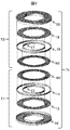
- FIG. 2 is a configuration diagram of a power feeding transformer of Embodiment 1.
- FIG. 2 is a configuration diagram of a power feeding transformer of Embodiment 1.
- 5 is a configuration diagram of a power feeding transformer of Embodiment 2.
- FIG. 7 is a configuration diagram of a power feeding transformer of a third embodiment.
- 10 is a configuration diagram of a power feeding transformer of Embodiment 4.
- FIG. FIG. 16 is a configuration diagram of a power feeding transformer of a fifth embodiment.
- FIG. 16 is a configuration diagram of a power feeding transformer of a fifth embodiment.
- FIG. 16 is a configuration diagram of a power feeding transformer of a sixth embodiment.
- FIG. 16 is a schematic configuration view showing a configuration of an X-ray CT apparatus 602 of a seventh embodiment.
- FIG. 16 is a configuration diagram of a power feeding transformer of a seventh embodiment.
- FIG. 16 is a configuration diagram of a power feeding transformer of a seventh embodiment.
- FIG. 16 is a configuration diagram of a power feeding transformer of an eighth embodiment.
- FIG. 1 is a schematic configuration diagram of a non-contact power feeding device 2 according to a first embodiment of the present invention.
- the non-contact power feeding device 2 includes a gantry fixing unit 4 and a rotating unit 5, and transmits electric power from the gantry fixing unit 4 to the rotating unit 5 in a non-contact manner by magnetic coupling with the power supply transformer Tr.
- the gantry fixing unit 4 includes a power feeding circuit 101 that receives the power of the AC power supply 1 and supplies high frequency power to the primary coil T1, and the primary coil T1.
- the feed circuit 101 includes an AC / DC converter 6 for outputting a DC link voltage, and a high frequency inverter 7 for supplying high frequency power to the primary coil T1 by outputting an AC voltage of an arbitrary frequency with the DC link voltage as an input.
- a control unit 9 and a communication unit 11 are provided.
- the AC / DC converter 6 and the high frequency inverter 7 are controlled by the control means 9 to control the frequencies of the DC link voltage and the AC voltage to arbitrary values.
- the rotary unit 5 magnetically couples with the primary coil T1 to form a power feeding transformer Tr, and loads the power of the secondary coil T2 that receives power from the primary coil T1 in a noncontact manner and the power of the secondary coil T2. And a load 3.
- the power receiving circuit 102 includes a rectifier circuit 8, a control unit 10, and a communication unit 12.
- the control means 9 and the control means 10 are connected wirelessly by the communication means 11 and the communication means 12.
- the control means 10 detects the output voltage and output current of the rectifier circuit 8.
- FIGS. 2 and 3 are block diagrams showing a first embodiment of a power supply transformer Tr according to the present invention.
- FIG. 2 is an exploded configuration view of the power supply transformer Tr.
- FIG. 3 (a) is a view of the power supply transformer Tr as viewed from the rotational axis direction
- FIG. 3 (b) is a view of a cross section taken along the line AB in FIG. 3 (a) as viewed from the arrow direction.
- the power feeding transformer Tr has an axial gap structure in which the primary coil T1 and the secondary coil T2 are disposed opposite to each other in the rotational axis direction via a gap.
- the primary coil T1 has an annularly wound primary winding N1, an inner peripheral core 13 and an outer peripheral core 14 formed along the inner periphery and the outer periphery of the primary winding N1, an inner peripheral core 13 and an outer peripheral core
- a bottom core 15 that magnetically couples 14 and a support member 16 are provided.
- the support member 16 supports the inner peripheral core 13, the outer peripheral core 14, and the bottom surface core 15 on the gantry fixing portion 4.
- the secondary coil T2 includes an annularly wound secondary winding N2, an inner peripheral core 17 and an outer peripheral core 18 formed along the inner periphery and the outer periphery of the secondary winding N2, and an inner peripheral core 17 And a bottom core 19 that magnetically couples the outer peripheral core 18 and a support member 20.
- the support member 20 supports the inner peripheral core 17, the outer peripheral core 18, and the bottom surface core 19 on the rotating portion 5.
- the shape of the core can be simplified by dividing the magnetic core of the primary coil T1 or the secondary coil T2 into the inner peripheral core, the outer peripheral core, and the bottom core.
- the core can be easily thinned as compared with the case of using the integrally molded core, and the power feeding transformer can be reduced in weight.
- the magnetic coupling between the feeding coils can be improved and the magnetic characteristics during rotation can be stabilized by opposingly arranging the inner peripheral core and / or the outer peripheral core.
- a fixing member for fixing the primary winding N1 and the secondary winding N2 to the support members 16 and 19 may be provided.
- an enameled wire single wire
- a litz wire may be used for the primary winding N1 and the secondary winding N2 .
- the present embodiment it is possible to simplify the shape of the core that constitutes the feed transformer. Thereby, the weight reduction of the feed transformer can be realized while stabilizing the magnetic characteristics.
- FIG. 4 is a cross-sectional view of a power feeding transformer Tr according to a second embodiment of the present invention.
- bottom cores 115 and 119 are arranged up to both ends of support members 116 and 120, primary winding N1 or secondary winding N2, and inner circumferential core 113. , 117 and / or the outer peripheral core 114, 118 and / or the bottom core 15, 19 in that the insulators 121, 122 are inserted.
- insulation between primary winding N1 or secondary winding N2 and the core is ensured by inserting an insulator between primary winding N1 or secondary winding N2 and the core.
- an insulator as a resin mold, it can be used as a supporting material for supporting the winding on the core.
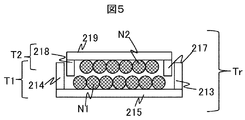
- FIG. 5 is an exploded configuration view of a power supply transformer Tr according to a third embodiment of the present invention.
- the difference from the first embodiment is that the primary winding N1 and / or the inner circumferential core 213 and / or the outer circumferential core 214 of the primary coil T1, and the secondary winding N1 and / or the inner circumferential core 217 of the secondary coil T2. And / or the outer peripheral core 218 has different diameters, and the inner peripheral core 217 and the outer peripheral core 218 are covered with the inner peripheral core 213 and the outer peripheral core 214.
- the facing area of the primary coil T1 and the secondary coil T2 can be increased, the magnetic coupling between the feeding coils can be improved.
- FIG. 6 is an exploded configuration view of a power supply transformer Tr according to a fourth embodiment of the present invention.
- bottom cores 315 and 319 of the primary coil T1 and the secondary coil T2 are divided in the radial direction of the primary winding N1 and the secondary winding N2.
- the bottom cores 315 and 319 of the primary coil T1 and the secondary coil T2 are divided into the same number, but the bottom core 315 of only one of the primary coil T1 or the secondary coil T2, 319 may be divided.
- the bottom core may be divided into different numbers by the primary coil T1 and the secondary coil T2.
- the bottom cores 315 and 319 are divided in the circumferential direction of the winding, but may be divided in the radial direction of the winding.
- the core member constituting the power supply transformer Tr can be further miniaturized, so that the strength of the core can be improved, and the core can be manufactured. This makes it possible to reduce the manufacturing cost of the power supply transformer.
- the bottom core since the bottom core can be miniaturized, the manufacture of the core becomes easier than in the first embodiment. Thereby, the manufacturing cost of the power supply transformer can be reduced.
- FIG. 7 is an exploded structural view of a power feeding transformer Tr according to a fifth embodiment of the present invention.
- Fig.8 (a) is a figure which showed the positional relationship of the inner peripheral core 413 of the primary coil T1 of Example 5 of this invention, the outer peripheral core 414, and the bottom face core 415
- FIG.8 (b) is this It is the figure which showed the positional relationship of the inner peripheral core 417 of the secondary coil T2 of Example 5 of the invention, the outer peripheral core 418, and the bottom face core 419.
- FIG. A difference from the first embodiment and the second embodiment is that the inner peripheral cores 413 and 417 and the outer peripheral cores 414 and 418 are divided into a plurality of parts.
- the number of core divisions of the inner peripheral cores 413 and 417 and the outer peripheral cores 414 and 418 is the same in the present embodiment, the number of core divisions may be different between the inner peripheral core and the outer peripheral core.
- the bottom cores 415 and 419 are disposed in the gap between the divided inner peripheral cores 413 and 417 and the outer peripheral cores 414 and 418, but the bottom cores 415 and 419 are inner peripheral cores. It is good also as composition arranged at the central part of 414,417 and perimeter cores 414,418.
- the core shape can be miniaturized and simplified, the core can be easily manufactured.
- the members can be made common to the inner and outer peripheral cores, so cost reduction of the power supply transformer can be realized.
- FIG. 9 (a) is a view showing the positional relationship between the inner peripheral core 513, the outer peripheral core 514, and the bottom core 515 of the primary coil T1 of the sixth embodiment of the present invention, and FIG. It is the figure which showed the positional relationship of the inner peripheral core 517 of secondary coil T2 of Example 6, the outer peripheral core 518, and the bottom face core 519.
- FIG. 9 (a) is a view showing the positional relationship between the inner peripheral core 513, the outer peripheral core 514, and the bottom core 515 of the primary coil T1 of the sixth embodiment of the present invention, and FIG. It is the figure which showed the positional relationship of the inner peripheral core 517 of secondary coil T2 of Example 6, the outer peripheral core 518, and the bottom face core 519.
- the difference from the third embodiment described above is that the inner peripheral cores 513 and 517 and the outer peripheral cores 514 and 518 are divided into different numbers in the primary coil T1 and the secondary coil T2.
- the division number of the core of the primary coil T1 is 7 (N), and the division number of the core of the secondary coil T2 is 6 (N-1).
- the present invention is not limited to this.
- the division number of the core of the primary coil T1 may be N-1, and the division number of the core of the secondary coil T2 may be N.
- the inner peripheral cores 513 and 517 and the outer peripheral cores 514 and 518 may be divided into different numbers.
- bottom cores 515 and 519 have different numbers for the primary coil T1 and the secondary coil T2, the number of bottom cores may be the same for the primary coil T1 and the secondary coil T2.
- the magnetic characteristics during rotation are improved as compared to the third embodiment. It can be stabilized.
- FIG. 10 is a view showing a schematic configuration of an X-ray CT apparatus 602 adopting the non-contact power feeding device 2 of the present invention.
- the X-ray CT apparatus 602 of this embodiment is divided into a gantry fixing unit 604 and a rotating unit 605.
- the rotating unit 605 is rotatably supported by the gantry fixing unit 604.
- the gantry fixing unit 604 has an AC power supply 1 as an input, an AC / DC converter 606 that generates a DC link voltage, and a DC link voltage as an input, generates an AC voltage of an arbitrary frequency, and primary coils T11 and T12. It includes high frequency inverters 607 and 621 for supplying high frequency power, primary coils T11 and T12, a control means 609, an image display unit 630, an image processing unit 631, and communication means 611 and 632.
- the rotating unit 605 is magnetically coupled to the primary coils T11 and T12 to form feed transformers Tr11 and Tr21, and secondary coils T21 and T22 that receive electric power from the primary coils T11 and T12 without contact, and a secondary A rectifier circuit 608 for rectifying the power of the coil T21 and supplying a high voltage DC voltage to the X-ray tube 627 which is the load 603, a rectifier circuit 622 for rectifying the power of the secondary coil T22, and the X-ray tube 627
- An inverter 623 for supplying power to a stator coil 624 for rotationally driving a rotating anode, an inverter 625 for transmitting power to a heating transformer 626 for heating a cathode included in an X-ray tube 627, an X-ray detection unit 628, control means 610, and communication means 612, 633.
- the control means 610 detects the output control of the inverters 623 and 625 and the output voltage and output current of the rectifier circuit 608.
- the control unit 609 and the control unit 610 are wirelessly connected by the communication unit 611 and the control unit 612.
- the X-ray detection unit 628 and the image processing unit 631 are wirelessly connected by the communication unit 632 and the communication unit 633.
- a different point from the first embodiment described above is that a power feeding transformer Tr21 of a different system from the power feeding transformer Tr is provided to perform power transmission to the stator coil 624 and the heating transformer 626.
- the X-ray tube 627 emits X-rays toward the subject 629 by being supplied with the DC voltage output from the rectifier circuit 608.
- the X-rays transmitted through the subject 629 enter the X-ray detection unit 628.
- the X-ray detection unit 628 detects an X-ray transmitted through the subject 629 and amplifies a detected signal, and is disposed to face the X-ray tube 627.
- the communication units 632 and 633 transmit the detection signal of the X-ray detection unit 628 from the rotation unit 605 to the gantry fixing unit 604.
- the detection signal received by the communication unit 632 is transmitted to the image processing device 631.
- the image processing device 631 generates a tomographic image of the subject 629 by processing the transmitted detection signal.
- the image display device 630 displays the tomographic image generated by the image processing device 631.
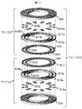
- FIG. 11 is an exploded configuration view of the feed transformers Tr11 and Tr21
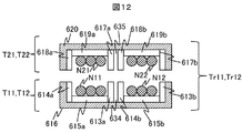
- FIG. 12 is a cross-sectional view of the feed transformers Tr11 and Tr21.
- the primary coil T11 includes an annularly wound primary winding N11, an inner peripheral core 613a and an outer peripheral core 614a formed along the inner periphery and the outer periphery of the primary winding N11, an inner peripheral core 613a and an outer peripheral core And a bottom core 615b that magnetically couples 614a.
- the primary coil T12 is formed along the inner periphery and the outer periphery of the primary winding N12 which is annularly wound along the inner periphery of the primary winding N11 via the air gap portion 634, and the primary winding N12.
- An inner peripheral core 613b, an outer peripheral core 614b, and a bottom core 615b that magnetically couples the inner peripheral core 613b and the outer peripheral core 614b are provided.
- the inner peripheral cores 613a and 613b, the outer peripheral cores 614a and 614b, and the bottom cores 615a and 615b are fixed to the gantry fixing portion 604 by the support member 616.
- the secondary coil T21 has an annularly wound secondary winding N21, an inner circumferential core 617a and an outer circumferential core 618a formed along the inner and outer circumferences of the secondary winding N21, and the inner circumferential core And a bottom core 619b that magnetically couples the core 617a and the outer core 618a.
- the secondary coil T22 is formed along the inner periphery and the outer periphery of the secondary winding N22 which is annularly wound along the inner periphery of the secondary winding N21 via the air gap portion 635, and the secondary winding N22. And a bottom core 619b for magnetically coupling the inner core 617b and the outer core 618b.
- the inner peripheral cores 617 a and 617 b, the outer peripheral cores 618 a and 618 b, and the bottom cores 619 a and 619 b are fixed to the rotating portion 605 by the support member 620.
- a common core may be used for the inner peripheral core 613a of the primary coil T11 and the outer peripheral core 614b of the primary coil T12.
- a core common to the inner peripheral core 617a and the outer peripheral core 618b may be used.
- segmented into the bottom face core 615a of the primary coil 11 and the bottom face core 615b of the primary coil T12 is used in this embodiment, you may use a common core.
- a core common to the bottom surface core 619a and the bottom surface core 619b may be used. As described above, by sharing the core, the number of parts constituting the feed transformer can be reduced, so that the number of assembling steps of the feed transformer Tr11 and the feed transformer Tr12 can be reduced.
- the shape of the core that constitutes the feed transformer can be simplified. This makes it possible to reduce the weight of the power supply transformer while stabilizing the magnetic characteristics.
- FIG. 13 is a cross-sectional view of power feeding transformers Tr12 and Tr22 according to an eighth embodiment of the present invention.
- the seventh embodiment differs from the seventh embodiment in that the power supply transformer Tr12 and the power supply transformer Tr22 share the primary coil T13, and the secondary coil T23 and the secondary coil T24 share the bottom core 719, and the secondary coil T23 A secondary winding N23 and an inner peripheral core 717 are provided, and the secondary coil T24 is configured to include a secondary winding N24 and an outer peripheral core 718.
- the primary coil T13 includes a primary winding N13, an inner peripheral core 713, an outer peripheral core 714, a bottom core 715, and a support member 716.
- the present embodiment by sharing the primary coil T13 with a plurality of feed transformers, it is possible to reduce the weight of the feed transformers disposed in the gantry fixing portion. Further, the number of parts of the power feeding transformer can be reduced, and the cost of the non-contact power feeding device can be reduced.
- this invention is not limited to these.
- the non-contact power feeding device having two power feeding transformers has been described, but the present invention can be applied to a non-contact power feeding device having three or more power feeding transformers. It is.
- the case where power is transmitted from the fixed unit to the rotating unit has been described. However, even when power is transmitted from the rotating unit to the fixed unit or when power is transmitted from the rotating unit to the rotating unit It is possible to apply the invention.
- the non-contact power feeding device of the present invention can be applied to a power supply device used for an X-ray CT apparatus, a power supply device for a wind power generator, a power supply device used for a surveillance camera, and the like.
- image processing device 13, 113, 213, 313, 413, 513, 613a, 613b, 17, 117, 217, 317, 417, 517, 617 , 617b, 713, 717 ... inner circumferential core, 14, 114, 214, 314, 414, 514, 614a, 614b, 18, 118, 218, 318, 418, 618a, 618b, 714, 718.
- Tr, Tr11, Tr12, Tr21, r22 feed transformer
- T1, T11, T12, T13 primary coil
- T2, T21, T22, T23, T24 secondary coil
- N1, N11, N12, N13 primary winding, N2, N21, N22, N23, N24 ... secondary winding
Landscapes
- Engineering & Computer Science (AREA)
- Power Engineering (AREA)
- Computer Networks & Wireless Communication (AREA)
- Coils Of Transformers For General Uses (AREA)
- Apparatus For Radiation Diagnosis (AREA)
Abstract
La présente invention a pour but de proposer un dispositif d'alimentation électrique sans contact permettant à un transformateur d'alimentation électrique de voir son poids réduit et aux propriétés magnétiques d'être stabilisées durant une rotation. La présente invention concerne un dispositif d'alimentation électrique sans contact comportant un premier circuit connecté à une source d'alimentation, un transformateur d'alimentation électrique et un second circuit fournissant de l'énergie à une charge, l'énergie électrique de la source d'alimentation étant transmise du premier circuit au second circuit par l'intermédiaire du transformateur d'alimentation électrique sans contact, caractérisé en ce que le transformateur d'alimentation électrique a une constitution dans laquelle un espace prédéterminé est pris en sandwich par une paire de bobines d'alimentation électrique disposées face à face et comprenant un fil d'enroulement enroulé dans un tore et au moins l'un parmi un noyau périphérique interne et un noyau périphérique externe formés le long de la périphérie interne et de la périphérie externe du fil enroulé, respectivement.
Priority Applications (2)
| Application Number | Priority Date | Filing Date | Title |
|---|---|---|---|
| JP2015530632A JPWO2015019478A1 (ja) | 2013-08-09 | 2013-08-09 | 非接触給電装置 |
| PCT/JP2013/071585 WO2015019478A1 (fr) | 2013-08-09 | 2013-08-09 | Dispositif d'alimentation électrique sans contact |
Applications Claiming Priority (1)
| Application Number | Priority Date | Filing Date | Title |
|---|---|---|---|
| PCT/JP2013/071585 WO2015019478A1 (fr) | 2013-08-09 | 2013-08-09 | Dispositif d'alimentation électrique sans contact |
Publications (1)
| Publication Number | Publication Date |
|---|---|
| WO2015019478A1 true WO2015019478A1 (fr) | 2015-02-12 |
Family
ID=52460845
Family Applications (1)
| Application Number | Title | Priority Date | Filing Date |
|---|---|---|---|
| PCT/JP2013/071585 Ceased WO2015019478A1 (fr) | 2013-08-09 | 2013-08-09 | Dispositif d'alimentation électrique sans contact |
Country Status (2)
| Country | Link |
|---|---|
| JP (1) | JPWO2015019478A1 (fr) |
| WO (1) | WO2015019478A1 (fr) |
Cited By (8)
| Publication number | Priority date | Publication date | Assignee | Title |
|---|---|---|---|---|
| WO2018026359A1 (fr) * | 2016-08-03 | 2018-02-08 | Analogic Corporation | Dispositif de couplage de puissance |
| EP3331128A1 (fr) | 2016-11-30 | 2018-06-06 | Panasonic Intellectual Property Management Co., Ltd. | Unité d'alimentation en énergie sans fil, module de transmission de puissance, module de réception d'énergie et système de transmission d'énergie sans fil |
| JP2020022279A (ja) * | 2018-08-01 | 2020-02-06 | ひだかや株式会社 | 自然力発電装置 |
| JP2020089045A (ja) * | 2018-11-22 | 2020-06-04 | Ntn株式会社 | 風力発電装置 |
| CN112022184A (zh) * | 2019-06-04 | 2020-12-04 | 台达电子工业股份有限公司 | 电脑断层扫描系统及其连接组件结构 |
| JP2021136800A (ja) * | 2020-02-27 | 2021-09-13 | 国立研究開発法人海洋研究開発機構 | ドリルパイプ多段接続体 |
| JP2022045903A (ja) * | 2020-09-09 | 2022-03-22 | スミダコーポレーション株式会社 | 電力伝送装置 |
| WO2026054236A1 (fr) * | 2024-09-04 | 2026-03-12 | 삼성전자주식회사 | Transformateur comprenant des bobines empilées, et dispositif électronique le comprenant |
Families Citing this family (1)
| Publication number | Priority date | Publication date | Assignee | Title |
|---|---|---|---|---|
| JP7182513B2 (ja) * | 2019-05-24 | 2022-12-02 | 株式会社Soken | 磁気部品及びこれを備えた電力変換装置 |
Citations (6)
| Publication number | Priority date | Publication date | Assignee | Title |
|---|---|---|---|---|
| JPS59166421U (ja) * | 1983-04-25 | 1984-11-08 | ソニー株式会社 | ロータリートランス |
| JPH03148102A (ja) * | 1989-11-02 | 1991-06-24 | Matsushita Electric Ind Co Ltd | 回転トランス |
| JP2000150276A (ja) * | 1998-11-17 | 2000-05-30 | Dainippon Printing Co Ltd | 電源伝送装置及びロータリージョイント |
| JP2001269330A (ja) * | 2000-01-17 | 2001-10-02 | Toshiba Corp | X線ct装置 |
| JP2002134340A (ja) * | 2000-10-20 | 2002-05-10 | Shinko Electric Co Ltd | 非接触給電トランス |
| JP2008243985A (ja) * | 2007-03-26 | 2008-10-09 | Nitta Ind Corp | 電力伝達装置のコア体 |
Family Cites Families (5)
| Publication number | Priority date | Publication date | Assignee | Title |
|---|---|---|---|---|
| JPS6120724Y2 (fr) * | 1980-12-05 | 1986-06-21 | ||
| JPS62193712U (fr) * | 1986-05-30 | 1987-12-09 | ||
| JPH02249103A (ja) * | 1989-03-23 | 1990-10-04 | Sharp Corp | 磁気記録再生装置 |
| JPH09275027A (ja) * | 1996-04-03 | 1997-10-21 | Sony Corp | ロータリートランス |
| JP4643797B2 (ja) * | 2000-05-29 | 2011-03-02 | 株式会社日立メディコ | ギャップ付き変圧器及びこれを用いた非接触給電装置並びにx線ct装置 |
-
2013
- 2013-08-09 WO PCT/JP2013/071585 patent/WO2015019478A1/fr not_active Ceased
- 2013-08-09 JP JP2015530632A patent/JPWO2015019478A1/ja active Pending
Patent Citations (6)
| Publication number | Priority date | Publication date | Assignee | Title |
|---|---|---|---|---|
| JPS59166421U (ja) * | 1983-04-25 | 1984-11-08 | ソニー株式会社 | ロータリートランス |
| JPH03148102A (ja) * | 1989-11-02 | 1991-06-24 | Matsushita Electric Ind Co Ltd | 回転トランス |
| JP2000150276A (ja) * | 1998-11-17 | 2000-05-30 | Dainippon Printing Co Ltd | 電源伝送装置及びロータリージョイント |
| JP2001269330A (ja) * | 2000-01-17 | 2001-10-02 | Toshiba Corp | X線ct装置 |
| JP2002134340A (ja) * | 2000-10-20 | 2002-05-10 | Shinko Electric Co Ltd | 非接触給電トランス |
| JP2008243985A (ja) * | 2007-03-26 | 2008-10-09 | Nitta Ind Corp | 電力伝達装置のコア体 |
Cited By (20)
| Publication number | Priority date | Publication date | Assignee | Title |
|---|---|---|---|---|
| WO2018026359A1 (fr) * | 2016-08-03 | 2018-02-08 | Analogic Corporation | Dispositif de couplage de puissance |
| US12456575B2 (en) | 2016-08-03 | 2025-10-28 | Analogic Corporation | Power coupling device |
| US11769628B2 (en) | 2016-08-03 | 2023-09-26 | Analogic Corporation | Power coupling device |
| CN115346752A (zh) * | 2016-08-03 | 2022-11-15 | 模拟技术公司 | 功率耦合装置 |
| CN109564808A (zh) * | 2016-08-03 | 2019-04-02 | 模拟技术公司 | 功率耦合装置 |
| EP3493362A1 (fr) | 2016-11-30 | 2019-06-05 | Panasonic Intellectual Property Management Co., Ltd. | Unité d'alimentation en énergie sans fil, module de transmission de puissance, module de réception d'énergie et système de transmission d'énergie sans fil |
| JP2018093706A (ja) * | 2016-11-30 | 2018-06-14 | パナソニックIpマネジメント株式会社 | 無線給電ユニット、送電モジュール、受電モジュールおよび無線電力伝送システム |
| EP3331128A1 (fr) | 2016-11-30 | 2018-06-06 | Panasonic Intellectual Property Management Co., Ltd. | Unité d'alimentation en énergie sans fil, module de transmission de puissance, module de réception d'énergie et système de transmission d'énergie sans fil |
| US10541565B2 (en) | 2016-11-30 | 2020-01-21 | Panasonic Intellectual Property Management Co., Ltd. | Wireless power feeding unit, power transmitting module, power receiving module, and wireless power transmission system |
| US10199880B2 (en) | 2016-11-30 | 2019-02-05 | Panasonic Intellectual Property Management Co., Ltd. | Wireless power feeding unit, power transmitting module, power receiving module, and wireless power transmission system |
| JP7174991B2 (ja) | 2018-08-01 | 2022-11-18 | ひだかや株式会社 | 自然力発電装置 |
| JP2020022279A (ja) * | 2018-08-01 | 2020-02-06 | ひだかや株式会社 | 自然力発電装置 |
| JP7252740B2 (ja) | 2018-11-22 | 2023-04-05 | Ntn株式会社 | 風力発電装置 |
| JP2020089045A (ja) * | 2018-11-22 | 2020-06-04 | Ntn株式会社 | 風力発電装置 |
| CN112022184A (zh) * | 2019-06-04 | 2020-12-04 | 台达电子工业股份有限公司 | 电脑断层扫描系统及其连接组件结构 |
| CN112022184B (zh) * | 2019-06-04 | 2023-12-19 | 台达电子工业股份有限公司 | 电脑断层扫描系统及其连接组件结构 |
| JP2021136800A (ja) * | 2020-02-27 | 2021-09-13 | 国立研究開発法人海洋研究開発機構 | ドリルパイプ多段接続体 |
| JP2022045903A (ja) * | 2020-09-09 | 2022-03-22 | スミダコーポレーション株式会社 | 電力伝送装置 |
| JP7735714B2 (ja) | 2020-09-09 | 2025-09-09 | スミダコーポレーション株式会社 | 電力伝送装置 |
| WO2026054236A1 (fr) * | 2024-09-04 | 2026-03-12 | 삼성전자주식회사 | Transformateur comprenant des bobines empilées, et dispositif électronique le comprenant |
Also Published As
| Publication number | Publication date |
|---|---|
| JPWO2015019478A1 (ja) | 2017-03-02 |
Similar Documents
| Publication | Publication Date | Title |
|---|---|---|
| WO2015019478A1 (fr) | Dispositif d'alimentation électrique sans contact | |
| EP2953143B1 (fr) | Unité de bobine et dispositif de transmission de puissance sans fil | |
| US7826586B2 (en) | X-ray CT device and method of imaging using the same | |
| JP6164421B2 (ja) | 送電コイルユニット及びワイヤレス電力伝送装置 | |
| EP2924842B1 (fr) | Unité de bobine et dispositif de transmission de puissance sans fil | |
| EP3035483B1 (fr) | Joint rotatif inductif avec des noyaux de ferrite en forme de U | |
| JP2015106579A (ja) | 送電コイルユニット及びワイヤレス電力伝送装置 | |
| JP6524175B2 (ja) | 電力伝送機構 | |
| JP6179160B2 (ja) | ワイヤレス電力伝送装置 | |
| JP2015106581A (ja) | 送電コイルユニット及びワイヤレス電力伝送装置 | |
| CN108695988A (zh) | 磁耦合装置以及使用其的无线电力传输系统 | |
| Han et al. | Design of coaxial coupled structure for distance-insensitive wireless power transfer | |
| JPH07204192A (ja) | X線ct装置 | |
| EP3214628B1 (fr) | Transformateur rotatif de fréquence de ligne pour portique de tomographie informatique | |
| US10825607B2 (en) | System and method for increasing coupling of an axle rotary transformer | |
| JP6340968B2 (ja) | コイルユニットおよびワイヤレス電力伝送装置 | |
| JP2015106938A (ja) | 送電コイルユニット及びワイヤレス電力伝送装置 | |
| US20150287499A1 (en) | Cable | |
| JP2014124056A (ja) | 回転式空中線への電力供給装置 | |
| JP5297129B2 (ja) | 非接触給電装置 | |
| JP2019170017A (ja) | ワイヤレス電力伝送システム | |
| JP2010119753A (ja) | X線ct装置 | |
| JP5595893B2 (ja) | 共鳴コイル及びそれを有する非接触電力伝送装置 | |
| JP2007151707A (ja) | X線ct装置 | |
| JP5595895B2 (ja) | 共鳴コイル及びそれを有する非接触電力伝送装置 |
Legal Events
| Date | Code | Title | Description |
|---|---|---|---|
| 121 | Ep: the epo has been informed by wipo that ep was designated in this application |
Ref document number: 13891315 Country of ref document: EP Kind code of ref document: A1 |
|
| ENP | Entry into the national phase |
Ref document number: 2015530632 Country of ref document: JP Kind code of ref document: A |
|
| NENP | Non-entry into the national phase |
Ref country code: DE |
|
| 122 | Ep: pct application non-entry in european phase |
Ref document number: 13891315 Country of ref document: EP Kind code of ref document: A1 |