WO2015019504A1 - Procédé de vérification, dispositif de vérification et programme de vérification - Google Patents
Procédé de vérification, dispositif de vérification et programme de vérification Download PDFInfo
- Publication number
- WO2015019504A1 WO2015019504A1 PCT/JP2013/071724 JP2013071724W WO2015019504A1 WO 2015019504 A1 WO2015019504 A1 WO 2015019504A1 JP 2013071724 W JP2013071724 W JP 2013071724W WO 2015019504 A1 WO2015019504 A1 WO 2015019504A1
- Authority
- WO
- WIPO (PCT)
- Prior art keywords
- program
- variable
- log
- difference
- deployment
- Prior art date
- Legal status (The legal status is an assumption and is not a legal conclusion. Google has not performed a legal analysis and makes no representation as to the accuracy of the status listed.)
- Ceased
Links
Images











Classifications
-
- G—PHYSICS
- G06—COMPUTING OR CALCULATING; COUNTING
- G06F—ELECTRIC DIGITAL DATA PROCESSING
- G06F11/00—Error detection; Error correction; Monitoring
- G06F11/07—Responding to the occurrence of a fault, e.g. fault tolerance
- G06F11/0703—Error or fault processing not based on redundancy, i.e. by taking additional measures to deal with the error or fault not making use of redundancy in operation, in hardware, or in data representation
-
- G—PHYSICS
- G06—COMPUTING OR CALCULATING; COUNTING
- G06F—ELECTRIC DIGITAL DATA PROCESSING
- G06F11/00—Error detection; Error correction; Monitoring
- G06F11/07—Responding to the occurrence of a fault, e.g. fault tolerance
- G06F11/0703—Error or fault processing not based on redundancy, i.e. by taking additional measures to deal with the error or fault not making use of redundancy in operation, in hardware, or in data representation
- G06F11/0706—Error or fault processing not based on redundancy, i.e. by taking additional measures to deal with the error or fault not making use of redundancy in operation, in hardware, or in data representation the processing taking place on a specific hardware platform or in a specific software environment
-
- G—PHYSICS
- G06—COMPUTING OR CALCULATING; COUNTING
- G06F—ELECTRIC DIGITAL DATA PROCESSING
- G06F11/00—Error detection; Error correction; Monitoring
- G06F11/07—Responding to the occurrence of a fault, e.g. fault tolerance
- G06F11/0703—Error or fault processing not based on redundancy, i.e. by taking additional measures to deal with the error or fault not making use of redundancy in operation, in hardware, or in data representation
- G06F11/0751—Error or fault detection not based on redundancy
-
- G—PHYSICS
- G06—COMPUTING OR CALCULATING; COUNTING
- G06F—ELECTRIC DIGITAL DATA PROCESSING
- G06F11/00—Error detection; Error correction; Monitoring
- G06F11/07—Responding to the occurrence of a fault, e.g. fault tolerance
- G06F11/0703—Error or fault processing not based on redundancy, i.e. by taking additional measures to deal with the error or fault not making use of redundancy in operation, in hardware, or in data representation
- G06F11/0766—Error or fault reporting or storing
- G06F11/0787—Storage of error reports, e.g. persistent data storage, storage using memory protection
-
- G—PHYSICS
- G06—COMPUTING OR CALCULATING; COUNTING
- G06F—ELECTRIC DIGITAL DATA PROCESSING
- G06F11/00—Error detection; Error correction; Monitoring
- G06F11/07—Responding to the occurrence of a fault, e.g. fault tolerance
- G06F11/0703—Error or fault processing not based on redundancy, i.e. by taking additional measures to deal with the error or fault not making use of redundancy in operation, in hardware, or in data representation
- G06F11/079—Root cause analysis, i.e. error or fault diagnosis
-
- G—PHYSICS
- G06—COMPUTING OR CALCULATING; COUNTING
- G06F—ELECTRIC DIGITAL DATA PROCESSING
- G06F11/00—Error detection; Error correction; Monitoring
- G06F11/30—Monitoring
- G06F11/3003—Monitoring arrangements specially adapted to the computing system or computing system component being monitored
- G06F11/302—Monitoring arrangements specially adapted to the computing system or computing system component being monitored where the computing system component is a software system
-
- G—PHYSICS
- G06—COMPUTING OR CALCULATING; COUNTING
- G06F—ELECTRIC DIGITAL DATA PROCESSING
- G06F11/00—Error detection; Error correction; Monitoring
- G06F11/30—Monitoring
- G06F11/34—Recording or statistical evaluation of computer activity, e.g. of down time, of input/output operation ; Recording or statistical evaluation of user activity, e.g. usability assessment
- G06F11/3466—Performance evaluation by tracing or monitoring
- G06F11/3476—Data logging
-
- G—PHYSICS
- G06—COMPUTING OR CALCULATING; COUNTING
- G06F—ELECTRIC DIGITAL DATA PROCESSING
- G06F11/00—Error detection; Error correction; Monitoring
- G06F11/36—Prevention of errors by analysis, debugging or testing of software
- G06F11/3604—Analysis of software for verifying properties of programs
- G06F11/3612—Analysis of software for verifying properties of programs by runtime analysis
-
- G—PHYSICS
- G06—COMPUTING OR CALCULATING; COUNTING
- G06F—ELECTRIC DIGITAL DATA PROCESSING
- G06F2201/00—Indexing scheme relating to error detection, to error correction, and to monitoring
- G06F2201/815—Virtual
-
- G—PHYSICS
- G06—COMPUTING OR CALCULATING; COUNTING
- G06F—ELECTRIC DIGITAL DATA PROCESSING
- G06F2201/00—Indexing scheme relating to error detection, to error correction, and to monitoring
- G06F2201/865—Monitoring of software
Definitions
- the present invention relates to a verification method, a verification device, and a verification program.
- a user can cause a computer to perform a predetermined function by causing a computer to execute a series of procedures using a program.
- software programs that provide business functions, software programs that support the operation of other software, and the like are used.
- a proposal to verify the validity of the setting contents by checking the setting parameters and type definitions set in the network components (for example, personal computers and servers) with the set parameter and type definition master. There is also.
- JP 2010-123030 A JP 2005-512196 Gazette
- a program including a plurality of program elements (for example, instructions and functions) indicating processing according to variables.
- a deployment program that supports the deployment of a virtual machine group, a software group, or the like on a plurality of computers may be used.
- the deployment program may include a plurality of program elements that perform various settings for operating a virtual machine or the like.
- a plurality of execution results can be generated by a plurality of program elements.
- the question is how to verify the validity of each execution result.
- an object of the present invention is to provide a verification method, a verification device, and a verification program that support appropriate grasp of factors that cause different execution results.
- a method for verifying a program including a plurality of program elements indicating processing corresponding to a variable is provided.
- this verification method when a computer executes a program, information for identifying a variable whose input content has been changed compared to when the program was executed in the past, and the program element and the program element are executed.
- the program element corresponding to the execution result and the log are referred to Searches for variables used in the program element, evaluates the factors that cause the difference in execution results and the validity of the differences based on the changes in the input contents for the variables, And information indicating the validity of the difference.
- a verification device used for verification of a program including a plurality of program elements indicating processing according to a variable includes a storage unit and a calculation unit.
- the storage unit stores a log indicating the execution status of the program.
- the arithmetic unit when executing the program, information for identifying a variable whose input content has been changed with respect to the execution of the program in the past, and an execution output by executing the program element and the program element
- the program element corresponding to the execution result and the program element are referred to by referring to the log Search for variables to be used, evaluate the factors that cause differences in execution results and the validity of the differences based on the changes in the input contents for the variables, and determine the differences between the execution results, the causes of differences, and the validity of the differences.
- the information indicating the gender is output.
- a verification program that is executed by a computer and that is used for verification of a program including a plurality of program elements indicating processing according to a variable is provided.
- this verification program when a program is executed, information for identifying a variable whose input content has been changed compared to when the program was executed in the past, and the program element and the program element are executed.
- the program element corresponding to the execution result and the log are referred to Searches for variables used in the program element, evaluates the factors that cause the difference in execution results and the validity of the differences based on the changes in the input contents for the variables, And processing to output information indicating the validity of the difference.
- FIG. 1 is a diagram illustrating a verification apparatus according to the first embodiment.
- the verification device 1 is used for verification of the program 2.
- the program 2 includes program elements 2a, 2b, and 2c.
- the program element is an instruction or a function (or a set of instructions) indicating processing (execution) according to a predetermined variable.
- the program element 2a shows processing according to the variable A.
- the program element 2b shows processing according to the variable B.
- the program element 2c shows processing according to the variable C.
- the verification device 1 includes a storage unit 1a and a calculation unit 1b.
- the storage unit 1a may be a volatile storage device such as a RAM (Random Access Memory) or a non-volatile storage device such as an HDD (Hard Disk Drive) or a flash memory.
- the arithmetic unit 1b may include a CPU (Central Processing Unit), a DSP (Digital Signal Processor), an ASIC (Application Specific Integrated Circuit), an FPGA (Field Programmable Gate Array), and the like.
- the calculation unit 1b may be a processor that executes a program.
- the “processor” may include a set of multiple processors (multiprocessor).
- the storage unit 1a stores a log 3 indicating the execution status of the program 2.
- the program 2 may be executed by the verification apparatus 1 or may be executed by another information processing apparatus.
- the calculation unit 1 b itself can record the log 3.
- the calculation unit 1b can acquire and record the contents of the log 3 from another information processing apparatus via a network. As described above, the calculation unit 1b can acquire the log 3 and store it in the storage unit 1a regardless of whether the program 2 is executed by the verification device 1 or another information processing device.
- the calculation unit 1b acquires the log 3 including information for identifying a variable whose input content is changed when the program 2 is executed in the past when the program 2 is executed. Information on the input contents of the variable may be included in the program 2 or may be prepared as data separate from the program 2.
- the calculation unit 1b determines the contents of the program 2 when the program 2 was executed in the past and the contents of the program 2 executed this time. By contrast, a variable whose input content has been changed can be detected.
- the calculation unit 1b changes the input content by comparing the past content of the data with the current content. Variable can be detected. Both methods may be used to detect a variable whose input has been changed. Note that the program 2 executed in the past and information on input contents are stored in the storage unit 1a.
- the execution time immediately before the current execution time (the previous execution time) can be considered.
- the computing unit 1b records in the log 3 information for identifying a variable whose input content has been changed between the previous execution and the current execution.
- the previous input contents of each variable are as follows.
- A 1.
- B 1.
- C A + 1.
- the input contents of each variable this time are as follows.
- A 2.
- B 1.
- C A + 1.
- the input content of variable A has been changed between the previous time and this time.
- the input contents of the variable B are not changed between the previous time and the current time.
- the definition of the variable C itself has not been changed between the previous time and the current time, the variable C depends on the variable A. Since the input content of the variable A is changed between the previous time and this time, the input content of the variable C is also changed between the previous time and this time. Therefore, in this case, the calculation unit 1b records in the log 3 that the variables A and C are changed.
- the calculation unit 1b records information indicating the correspondence between the program element and the execution result output by executing the program element in the log 3. For example, along with the execution of the program 2, the program element 2a calculates “$ A + 1” ($ A indicates a value assigned to the variable A. The same applies hereinafter), and “result1.dat” is the execution result. Is output.
- the program element 2b calculates "$ B ⁇ * 2" (" ⁇ *" indicates multiplication), and outputs "result2.dat” as the execution result.
- the program element 2c calculates “$ C + 1” and outputs “result3.dat” as the execution result.
- the calculation unit 1b records the correspondence between the program element 2a and the execution result “result1.dat” in the log 3. Correspondence between the program element 2 b and the execution result “result2.dat” is recorded in the log 3. The correspondence between the program element 2 c and the execution result “result3.dat” is recorded in the log 3. The calculation unit 1b stores the execution results of the program 2 in the storage unit 1a for the past.
- the arithmetic unit 1b refers to the log 3 stored in the storage unit 1a and determines the program element corresponding to the execution result and the program element. Search for variables to be used.
- the computing unit 1b refers to the log 3 and searches for the program element 2a corresponding to the execution result and the variable A used for the program element 2a.
- the contents of the execution result “result2.dat” are different between the previous time (“4”) and the current time (“2”). Therefore, the computing unit 1b refers to the log 3 and searches for the program element 2b corresponding to the execution result and the variable B used for the program element 2b.
- the contents of the execution result “result3.dat” are different between the previous time (“3”) and the current time (“4”).
- the computing unit 1b refers to the log 3 and searches for the program element 2c corresponding to the execution result and the variable C used for the program element 2c.
- the computing unit 1b may retrieve each variable used for each program element from the description of the program 2. Alternatively, a list of program elements and variables may be prepared in advance, and variables used for the program elements may be searched from the list.
- the calculation unit 1b refers to the log 3 stored in the storage unit 1a, evaluates the cause of the difference in the execution result and the validity of the difference based on the change status of the input content with respect to the searched variable, and evaluates Information indicating the result and the location where the execution result is different is output.
- the criterion of the validity of the result depends on the property expected for the program 2. For example, if you want program 2 to be idempotent (the same input can get the same result no matter how many times it is executed), the result is valid when the same result is obtained for the same input. It is. On the other hand, if the same result is not obtained for the same input, the result is not valid.
- the output of the calculation unit 1b is as follows.
- the log 3 records that the input content of the variable A has been changed as described above.
- the change in the input content of the variable A of the program element 2a is considered to be a cause of the difference in the execution result between the previous time and the current time.
- the calculation unit 1b outputs (a1) the fact that the input content for the variable A of the program element 2a has been changed as a factor of difference.
- A2 Since the input to the program element 2a has changed, it is output that the difference in the execution result is appropriate.
- (a3) information on a different execution result “result1.dat” is output (the difference portion in the data may be output. The same applies hereinafter).
- log 3 does not record that the input contents of variable B have changed.
- the program element 2b is considered not to be idempotent. Therefore, the calculation unit 1b outputs (b1) the program element 2b as a factor of difference.
- B2 Since the program element 2b has no idempotency, it outputs that the difference in the execution result is not appropriate. Further, (b3) information on a different execution result “result2.dat” is output.
- log 3 records that there was a change in the input contents of variable C as described above.
- the change in the input contents of the variable C of the program element 2c is a cause of the difference in execution results between the previous time and the current time.
- the calculation unit 1b outputs (c1) that the input content for the variable C of the program element 2c has been changed as a factor of difference.
- C2 Since the input to the program element 2c has changed, it is output that the difference in the execution result is appropriate. Further, (c3) information on a different execution result “result3.dat” is output.
- the verification device 1 when the program 2 is executed by the calculation unit 1b, the information for identifying the variables A and C whose input contents have been changed with respect to the previous execution of the program 2, and the program elements 2a, Information indicating the correspondence between the execution results 2b and 2c and the execution results output when the program elements 2a, 2b and 2c are executed is recorded in the log 3.
- the calculation unit 1b refers to the log 3 and searches for a program element corresponding to the execution result and a variable used for the program element. .
- the calculation unit 1b refers to the log 3 and evaluates the cause of the difference in the execution result and the validity of the difference based on the change status of the input content with respect to the retrieved variable. Information indicating different locations is output.
- the user can appropriately and quickly determine that the difference in the execution result of the program element 2b is not appropriate by referring to the outputs (b1) to (b3).
- the difference is not due to a change in input but is caused by the fact that the program element 2b does not have the required property (for example, idempotency).
- the user can start the review of the program element 2b quickly. For example, it is possible to quickly determine whether there is a problem in the processing of the program element 2b itself or whether the program element 2b has been rewritten from a past description.
- the calculation unit 1b may convert the program 2 so that the verification device 1 that executes the program 2 or another information processing device generates the log 3. Alternatively, it may be considered that the program after such conversion is the program 2. In this case, it is not necessary to force the user to insert the code for outputting the log 3 into the program 2, and efficient verification work can be supported.
- various methods can be considered to determine whether or not the input content for the variable has been changed.
- the presence / absence of a change may be determined by directly comparing the input contents of the current time and the previous time.
- the second variable included in the assignment statement of the first variable is detected, and the input to the first variable is determined based on whether or not the input content for the second variable is changed. It may be determined whether or not the content has been changed.
- the calculation unit 1b may determine whether or not the code of each program element itself has been changed by comparing the description of each program element with the past execution, and may output it to the log 3. In this way, the validity of the difference in the result data can be verified by taking into account the code change of the program element itself. For example, if there is a code change in the program element 2b between the previous time and the current time, even if the result is different between the previous time and the current time, the difference may be evaluated as valid. Thereby, a user's work burden can further be reduced and efficient verification work can be supported.
- a specific example of the program 2 is a deployment program that deploys a virtual machine, software, or the like to the information processing apparatus.
- the deployment program is verified. However, it does not prevent application to other types of programs.
- FIG. 2 illustrates an information processing system according to the second embodiment.
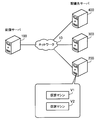
- the information processing system according to the second embodiment includes a deployment server 100 and deployment destination servers 200, 300, and 400.
- the deployment server 100 and the deployment destination servers 200, 300, and 400 are connected to the network 10.
- the network 10 may be a LAN (Local Area Network) or a wide area network such as a WAN (Wide Area Network) or the Internet.
- the deployment server 100 is a server computer that controls the deployment of virtual machines and predetermined software (hereinafter simply referred to as virtual machine deployment) to the deployment destination servers 200, 300, and 400.
- the deployment server 100 deploys virtual machines using a deployment program. Examples of the deployment program include chef, puppet, and rundeck.
- the user creates a deployment program according to the specifications of the information processing system and causes the deployment server 100 to execute the deployment program.
- the deployment program a code indicating a series of instructions (scripts) for setting a disk, a network, a user account, and the like by the user is described.
- the deployment program may be called a deployment script.
- the deployment server 100 causes the deployment destination servers 200, 300, and 400 to perform settings such as a disk, a network, and a user account in accordance with the contents described in the deployment program.
- the deployment destination servers 200, 300, and 400 are server computers that can execute a plurality of virtual machines.
- the deployment destination servers 200, 300, and 400 execute software called a hypervisor.
- the hypervisor allocates resources such as the CPU and RAM of the deployment destination servers 200, 300, and 400 to the virtual machine.
- the virtual machines V1 and V2 are executed using the allocated resources.
- the deployment destination servers 200, 300, and 400 set the operating environment of the virtual machine according to the instruction of the deployment server 100.
- a deployment client application that cooperates with the deployment server 100 is executed on the deployment destination servers 200, 300, and 400.
- the deployment procedure of a plurality of virtual machines having the same setting contents is often described in one deployment program.
- a large number of virtual machines can be deployed to the deployment destination servers 200, 300, and 400 using a single deployment program.
- the deployment of all virtual machines is re-executed by the deployment program. This is because it is more efficient to redeploy all virtual machines than to check and correct the settings individually.
- the deployment program when deploying multiple virtual machines using the deployment program, even if there are some virtual machines that failed in the deployment procedure, all virtual machines are redeployed without specifying the virtual machines. . Also, for example, when adding an account to the virtual machine, the parameter input to the deployment program is changed without preparing a separate account setting program, and the entire deployment program is re-executed.
- the deployment program is required to be idempotent. Specifically, it is desirable that the result does not change even if the same virtual machine that has not failed in the deployment procedure is redeployed. Further, for example, it is desirable that the setting result does not change even after redeployment with respect to a setting (for example, network setting) that is not related to the changed setting (for example, account setting).
- a setting for example, network setting
- the changed setting for example, account setting
- the second embodiment provides a function that supports verification of the idempotency of the deployment program.
- the verification can be performed using, for example, one deployment destination server (for example, the deployment destination server 200). In the following, it is assumed that verification is performed using the deployment destination server 200.
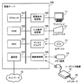
- FIG. 3 is a diagram illustrating a hardware example of the deployment server.
- the deployment server 100 includes a processor 101, a RAM (Random Access Memory) 102, an HDD (Hard Disk Drive) 103, a communication unit 104, an image signal processing unit 105, an input signal processing unit 106, a disk drive 107, and a device connection unit 108. . Each unit is connected to the bus of the deployment server 100.
- the deployment destination servers 200, 300, and 400 can also be realized using the same units as the deployment server 100.
- the processor 101 controls information processing of the deployment server 100.
- the processor 101 may be a multiprocessor.
- the processor 101 is, for example, a CPU, MPU (Micro Processing Unit), DSP, ASIC, FPGA, or PLD (Programmable Logic Device).
- the processor 101 may be a combination of two or more elements of CPU, MPU, DSP, ASIC, FPGA, and PLD.
- the RAM 102 is a main storage device of the deployment server 100.
- the RAM 102 temporarily stores at least part of an OS (Operating System) program and application programs to be executed by the processor 101.
- the RAM 102 stores various data used for processing by the processor 101.
- the HDD 103 is an auxiliary storage device of the deployment server 100.
- the HDD 103 magnetically writes and reads data to and from the built-in magnetic disk.
- the HDD 103 stores an OS program, application programs, and various data.
- the deployment server 100 may include other types of auxiliary storage devices such as flash memory and SSD (Solid State Drive), or may include a plurality of auxiliary storage devices.
- the communication unit 104 is an interface that can communicate with other computers via the network 10.
- the communication unit 104 may be a wired interface or a wireless interface.
- the image signal processing unit 105 outputs an image to the display 11 connected to the deployment server 100 in accordance with an instruction from the processor 101.
- a CRT (CathodeathRay Tube) display As the display 11, a CRT (CathodeathRay Tube) display, a liquid crystal display, or the like can be used.
- the input signal processing unit 106 acquires an input signal from the input device 12 connected to the deployment server 100 and outputs it to the processor 101.
- the input device 12 for example, a pointing device such as a mouse or a touch panel, a keyboard, or the like can be used.
- the disk drive 107 is a drive device that reads a program and data recorded on the optical disk 13 using a laser beam or the like.
- the optical disc 13 for example, a DVD (Digital Versatile Disc), DVD-RAM, CD-ROM (Compact Disc Read Only Memory), CD-R (Recordable) / RW (ReWritable) or the like can be used.
- the disk drive 107 stores the program and data read from the optical disk 13 in the RAM 102 or the HDD 103 in accordance with an instruction from the processor 101.
- the device connection unit 108 is a communication interface for connecting peripheral devices to the deployment server 100.
- the memory device 14 and the reader / writer device 15 can be connected to the device connection unit 108.
- the memory device 14 is a recording medium equipped with a communication function with the device connection unit 108.
- the reader / writer device 15 is a device that writes data to the memory card 16 or reads data from the memory card 16.
- the memory card 16 is a card-type recording medium.
- the device connection unit 108 stores a program or data read from the memory device 14 or the memory card 16 in the RAM 102 or the HDD 103 in accordance with an instruction from the processor 101.
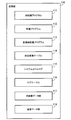
- FIG. 4 is a diagram illustrating a function example of the deployment server.
- the deployment server 100 includes a storage unit 110, a program conversion unit 120, a deployment execution unit 130, and a verification unit 140.
- the storage unit 110 can be realized as a storage area secured in the RAM 102 or the HDD 103.
- the program conversion unit 120, the deployment execution unit 130, and the verification unit 140 can be realized as software modules executed by the processor 101.
- the storage unit 110 stores various data used for processing of the program conversion unit 120, the deployment execution unit 130, and the verification unit 140.
- the data stored in the storage unit 110 includes a deployment program and a log generated with the execution of the deployment program.
- the deployment program is created by the user and stored in the storage unit 110 in advance.
- the program conversion unit 120 generates a post-conversion deployment program by converting the deployment program stored in the storage unit 110.
- the program conversion unit 120 stores the converted deployment program in the storage unit 110. Specifically, the program conversion unit 120 performs the following conversion.
- the program conversion unit 120 compares the previous input content and the current input content with respect to the variable of the deployment program, and detects a variable whose input content has been changed. And the program conversion part 120 converts a deployment program so that the log which shows that the input content about the said variable is changed is output.
- the program conversion unit 120 performs labeling in units of blocks (identified by block IDs (IDentifiers)) obtained by dividing the codes in the deployment program according to the setting contents.
- the program conversion unit 120 converts the deployment program so as to output a log indicating the execution of each block. Then, as will be described later, the correspondence between the block and the result data (execution result) output by executing the code in the block can be easily identified by the log. In addition, if the correspondence between blocks and variables is known in advance, the variables involved in the result data can be easily identified by the log.
- the block is an example of a program element according to the first embodiment.
- the deployment execution unit 130 deploys the virtual machine group to the deployment destination server 200 by providing the deployment destination server 200 with the contents of the post-conversion deployment program generated by the program conversion unit 120.
- the deployment destination server 200 generates a log indicating the execution status of the post-conversion deployment program in accordance with the description of the post-conversion deployment program, and provides the generated log to the deployment execution unit 130.
- the deployment execution unit 130 stores the log in the storage unit 110.
- the deployment execution unit 130 acquires a plurality of result data created with the deployment of the virtual machine from the deployment destination server 200 and stores the result data in the storage unit 110. Each result data is acquired and held in the storage unit 110 every time the deployment program is executed.
- the verification unit 140 verifies the idempotency of the deployment program by analyzing the log and result data stored in the storage unit 110.
- the case where the verification by the verification unit 140 is a case where result data having contents different from the previous time is obtained.
- the specifications of the operating environment of the virtual machine can be changed as appropriate. Along with this, the input contents of variables to the block are changed by the user, or the code in the block is rewritten. For this reason, just examining the difference in result data is not sufficient for verifying idempotency. This is because the input to the block that has output the result data may have been changed.
- the verification unit 140 refers to the log and searches for a block corresponding to the result data different from the previous one and a variable used for the block. Further, the verification unit 140 refers to the log and grasps the change status of the input content for the searched variable. The verification unit 140 evaluates the cause of the difference in the result data and the validity of the difference based on the change state of the input content with respect to the variable of the block. The verification unit 140 outputs the evaluation result and result data that has different contents from the previous time. For example, the verification unit 140 displays the output content on the display 11.
- FIG. 5 is a diagram illustrating an example of data stored in the storage unit.
- the storage unit 110 stores an old deployment program 111, a deployment program 112, a post-conversion deployment program 113, a free variable table 114, a system call log 115, a log table 116, an old result data group 117, and a result data group 118.
- the old deployment program 111 is a deployment program created by the user in order to deploy the previous virtual machine.
- the deployment program 112 is a deployment program created by the user in order to deploy the current virtual machine.
- the post-conversion deployment program 113 is a post-conversion deployment program generated by converting the deployment program 112 by the program conversion unit 120. As described above, the program conversion unit 120 converts the deployment program 112 and generates the post-conversion deployment program 113 so that a predetermined log regarding variables and blocks can be recorded.
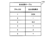
- the free variable table 114 is information in which the correspondence between the free variable used in the deployment program and the block in which the free variable is used is registered.
- a free variable is a variable that is not bound in the block (the substitution value is not limited by the code in the block). It can also be said that the free variable is an input given from outside the block. In the following description, a variable is simply a free variable (however, when a free variable is emphasized, it may be clearly indicated as a free variable).
- the system call log 115 is a system call log generated by the deployment destination server 200 when the virtual machine is deployed.
- the system call log 115 includes a predetermined log (log related to variables and blocks) based on the post-conversion deployment program 113. For example, if Unix (registered trademark) is used for the OS of the deployment destination server 200, a system call log can be obtained by a truss command. Alternatively, if Linux (registered trademark) is used for the OS of the deployment destination server 200, a system call log can be obtained by a “trace” command. For example, before performing the deployment using the post-conversion deployment program 113, the deployment execution unit 130 causes the deployment destination server 200 to execute these commands so that the system call log can be acquired.
- Unix registered trademark
- Linux registered trademark
- the log table 116 is information obtained by converting the system call log 115.
- the log table 116 includes information for identifying a variable whose input content has been changed.
- the log table 116 includes a correspondence between a block and result data output by processing of the block.
- the old result data group 117 is a set of old result data generated by the deployment destination server 200 by the previous deployment.
- the old result data includes data in which parameters for operating the network, account, various software, and the like generated with the deployment of the virtual machine are set.
- the result data group 118 is a set of result data generated by the deployment destination server 200 by this deployment. Similar to the old result data group 117, the result data includes data in which parameters for operating the network, account, and various software generated with the deployment of the virtual machine are set.
- the system call log 115, the old result data group 117, and the result data group 118 may be stored in a storage device provided in the deployment destination server 200.
- the deployment server 100 can acquire these pieces of information from the deployment destination server 200 in accordance with the processing of the deployment server 100.
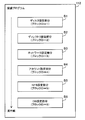
- FIG. 6 is a diagram illustrating an example of blocks included in the deployment program.
- the deployment program 112 includes various blocks (program elements) for setting the operating environment of the virtual machine. Normally, one setting item is described continuously in a part of the deployment program.
- the deployment program 112 includes a disk setting part B1, a directory setting part B2, a network setting part B3, an account setting part B4, an NFS (Network File System) setting part B5, and a DB (DataBase) setting part B6.
- NFS Network File System
- DB DataBase
- the disk setting part B1 is a block for creating a device file for the hard disk.
- the directory setting part B2 is a block for creating a directory.
- the network setting part B3 is a block for performing settings related to the network.
- the account setting part B4 is a block for performing user account setting.
- the NFS setting part B5 is a block for setting an NFS server.
- the DB setting part B6 is a block for setting a DBMS (DataBase Management System).
- disk setting, directory setting, network setting, account setting, NFS setting, and DB setting are performed in order from the upper side to the lower side.
- setting each item of the virtual machine in the above order is an example.
- Settings other than the exemplified items may be performed, and the order of settings that can be performed in an arbitrary order may be changed.
- Other items may be set instead of the exemplified items.
- the program conversion unit 120 identifies each block of the deployment program 112 and labels it with a block ID.
- the block ID of the disk setting portion B1 is set to “1”.
- the block ID of the directory setting portion B2 is “2”.
- the block ID of the network setting portion B3 is “3”.
- the block ID of the account setting portion B4 is “4”.
- the block ID of the NFS setting part B5 is set to “5”.
- the block ID of the DB setting part B6 is set to “6”.
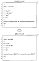
- FIG. 7 is a diagram showing an example of a deployment program.
- FIG. 7 illustrates some contents of the old deployment program 111 and the deployment program 112.
- the contents of the old deployment program 111 and the deployment program 112 are indicated by the line numbers given in FIG. 7 (in addition, for the omitted lines, one line number (for example, “ 1 "). The same applies hereinafter.
- each line has the following description.
- the ninth line is “execute“ pvcreate # ⁇ DISK ⁇ ”do command“ pvcreate # ⁇ DISK ⁇ ””.
- the tenth line is “end”.
- “f (X)” included in the definition of the variable Z indicates a predetermined function using the variable X (the variable X is included in the description of the definition of the variable Z).
- variable Z depends on the variable X.
- f (x) is an operation for obtaining an IP address obtained by adding 1 to the host address part of the IP (Internet Protocol) address indicated by the variable X (however, another operation may be performed on the variable X).
- each line has the following description.
- the ninth line is “execute“ pvcreate # ⁇ DISK ⁇ ”do command“ pvcreate # ⁇ DISK ⁇ ””.
- the tenth line is “end”.
- the second and fourth to seventh lines are assignment statements for the variables DISK, W, X, Y, and Z, respectively.
- commands “execute” and “end” are used, and one setting content is described between these two commands.
- a command “execute” indicating execution of setting is described.
- end indicating the end of one setting is described in the following 10th line. Therefore, one set content is in the 9th to 10th lines. In this case, the ninth to tenth lines are one block.
- the variable name (“DISK”, “X”, etc.)
- the ninth line includes the character string “# ⁇ DISK ⁇ ”. Therefore, the blocks in the 9th to 10th lines are blocks using the variable DISK.
- the description on the second line has changed.
- the description on the fourth line is not changed.
- the description on the fifth line has been changed.
- the description on the sixth line has been changed.
- the description on the seventh line has not been changed (however, as will be described later, the value assigned to the variable Z is another judgment).
- the description on line 9 is unchanged.
- the description on the 10th line is not changed.
- the program conversion unit 120 can extract variables and blocks from the old deployment program 111 and the deployment program 112 in accordance with the syntax rules as described above.
- the syntax rules used at that time are given to the program conversion unit 120 in advance.
- FIG. 8 is a diagram showing an example of the post-conversion deployment program.
- the post-conversion deployment program 113 is a result of the deployment program 112 being converted by the program conversion unit 120.
- the contents of the post-conversion deployment program 113 are indicated by the line numbers given in FIG.
- the post-conversion deployment program 113 has the following description, for example.
- the third line is “log_write (“ DISK changed ”)”.
- the seventh line is “log_write (“ X changed ”)”.
- the ninth line is “log_write (“ Y changed ”)”.
- the eleventh line is “log_write (“ Z changed; use X ”)”.
- the 13th line is “log_write (“ block 1 enter ”)”.
- the 14th line is “execute“ pvcreate # ⁇ DISK ⁇ ”do command“ pvcreate # ⁇ DISK ⁇ ””.
- the 15th line is “end”.
- the 16th line is “log_write (“ block 1 exit ”)”.
- the third, seventh, ninth, eleventh, thirteenth and sixteenth lines are codes inserted by the program conversion unit 120.
- the function “log_write (“ ⁇ character string> ”)” causes the deployment destination server 200 to output the character string described in the “ ⁇ character string>” portion to the system call log 115.
- the function is registered in advance in the function library of the deployment destination server 200.
- the deployment destination server 200 outputs a character string “DISK changed” to the system call log 115. This indicates that the input content of the variable DISK has been changed.
- the description “log_write (“ Z changed; use X ”)” on the eleventh line indicates that the input content for the variable Z has been changed.
- the portion “use X” indicates that the input content of the variable Z depends on the input content of the variable X.
- the definition of the variable Z itself is not changed.
- the program conversion unit 120 considers that the input content of the variable Z has also been changed.
- FIG. 9 is a diagram showing an example of a free variable table.
- the free variable table 114 is generated by the program conversion unit 120.
- the free variable table 114 includes items of a block ID and a free variable set.
- the block ID is registered in the block ID item.
- In the free variable set item a set of free variables used in the block indicated by the block ID is registered.
- the free variable table 114 information that the block ID is “2” and the free variable set is not set “ ⁇ (hyphen)” is registered. This indicates that there is no free variable used in the block with the block ID “2”.
- the free variable table 114 In the free variable table 114, information that the block ID is “3” and the free variable set is “W, X” is registered. This indicates that the free variables W and X are used in the block with the block ID “3”.
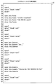
- FIG. 10 is a diagram showing an example of a system call log.
- the system call log 115 is generated by the deployment destination server 200.
- the contents of the system call log 115 are indicated by the line numbers given in FIG.
- the system call log 115 has the following description, for example.
- the second line is “open f”. “F” indicates a predetermined file.
- the second line is a file open process indicated by “f”.
- the third line is “write f“ DISK changed ””. Indicates that “DISK changed” has been written in the file indicated by “f”.
- the fourth line is “close f”. This is a file closing process indicated by “f”.
- Lines 6 to 8 ("X change” written to “f"), lines 10 to 12 ("Y changed” written to “f"), lines 14 to 16 ( “Z changed; use X”) to “f” also shows the same processing. The same processing is also applied to the 18th to 20th lines (writing “block 1 enter” to “f”) and the 26th to 28th lines (writing “block 1 exit” to “f”). Show.
- the 22nd line is “open / var / log / messages”. This is an open process of the “/ var / log / messages” file.
- the 23rd line is “write / var / log / messages” / dev / hda0 created ”. Indicates that “/ dev / hda0 created” has been written to the file.
- the 24th line is “close / var / log / messages”. This is a process for closing the file.
- FIG. 11 is a diagram showing an example (continued) of the system call log. Further, the system call log 115 has the following description, for example. Lines 31 to 33, lines 40 to 42, lines 44 to 46, lines 52 to 54, lines 56 to 58, lines 64 to 66 are described above. Are the same as the 18th to 20th lines and the 26th to 28th lines (the recorded block IDs are different).
- the 35th line is “open / etc / hosts”. “/ Etc / hosts” file open process.
- the 36th line is “write / etc / hosts” 127.0.0.1 localhost ”. Indicates that “127.0.0.1 localhost” has been written to the file.
- the 37th line is "write / etc / hosts” 192.168.10.1 pochi ". Indicates that “192.168.10.1 pochi” has been written to the file.
- the 38th line is “close / etc / hosts”. This is a process for closing the file.
- the 48th line is “open / etc / passwd”. This is an open process of the “/ etc / passwd” file.
- Line 49 is “write / etc / passwd” “jiro. . . "”. Indicates that "jiro " has been written to the same file.
- the 50th line is “close / etc / passwd”. This is a process for closing the file.
- the 60th line is “open / etc / exports”. This is an open process of the “/ etc / exports” file.
- the 61st line is “write / etc / exports” / home / nfs 192.168.10.2/24 (rw) ”. This indicates that “/ home / nfs 192.168.10.2/24 (rw)” has been written to the file.
- the 62nd line is “close / etc / exports”. This is a process for closing the file.
- FIG. 12 is a diagram illustrating an example of a log table.
- the log table 116 is generated by the verification unit 140 based on the system call log 115.
- the log table 116 includes block ID and log items.
- the block ID is registered in the block ID item. However, there is a record in which no block ID is registered. When no block ID is registered, the record relates to a change in input contents for a variable. In the log item, the description content of the log is registered.
- log table 116 information that the block ID is “1” and the log is “block 1 enter” is registered. This corresponds to the description on the 19th line of the system call log 115 illustrated in FIG. This record indicates that the log “block 1 enter” indicating the start of execution of the block is recorded for the block with the block ID “1”. Further, it indicates that the following description relates to the block with the block ID “1”.
- log table 116 information that the block ID is “1” and the log is “write / var / log / messages” / dev / hda0 created ”is registered. This corresponds to the description on the 23rd line of the system call log 115 illustrated in FIG. This record indicates that a device file “/ dev / hda0” is created by the processing of the block with the block ID “1”, and the result is written in the “/ var / log / messages” file.
- FIG. 13 is a flowchart showing the entire verification process. In the following, the process illustrated in FIG. 13 will be described in order of step number.
- S1 The program conversion unit 120 generates the post-conversion deployment program 113 by converting the deployment program 112 to be verified. Details of the conversion process will be described later.
- the deployment execution unit 130 uses the post-conversion deployment program 113 to deploy the virtual machine to the deployment destination server 200. Specifically, the deployment execution unit 130 sets the operating environment of the virtual machine by providing a command for each block included in the post-conversion deployment program 113 to the deployment destination server 200. In the deployment destination server 200, the system call log 115 is generated as the deployment is executed. In addition, the deployment destination server 200 generates a result data group 118 according to the command of each block of the post-conversion deployment program 113.
- the deployment execution unit 130 acquires the system call log 115 and the result data group 118 from the deployment destination server 200 and stores them in the storage unit 110.
- the result data group 118 includes the results such as “messages” (log file), “hosts” (static definition file of the host name), “passwd” (account setting file), “exports” (NFS setting file), etc. Contains data.
- the verification unit 140 creates the log table 116 based on the system call log 115 stored in the storage unit 110. Specifically, in the system call log 115, the output contents to the file “f” relating to the variable are registered in the log table 116 without the block ID (“ ⁇ ”). In the example of the log table 116, the description of “write f” is also omitted for the variable log. Further, the verification unit 140 registers the output contents to each file related to the block in the system call log 115 in association with each other so that the block ID of the block and the output destination file can be known. The specific contents of the log table 116 are as illustrated in FIG.
- the verification unit 140 verifies the idempotency of the deployment program 112 by analyzing the log table 116 and the result data group 118.
- the verification unit 140 outputs a verification result.
- the verification unit 140 presents the verification result to the user by causing the display 11 to display an image indicating the verification result.
- FIG. 14 is a flowchart showing a conversion example of the deployment program. In the following, the process illustrated in FIG. 14 will be described in order of step number. The process shown below corresponds to step S1 in FIG.
- the program conversion unit 120 accepts designation by the user of the old deployment program 111 as a comparison target for verification. Further, the program conversion unit 120 accepts designation by the user of the deployment program 112 as a verification target.
- the program conversion unit 120 compares the old deployment program 111 and the deployment program 112, and searches for one variable having a different substitution value from the old deployment program 111 among the variables of the deployment program 112. Variables for which subsequent steps S14 to S16 have been executed are excluded from the search target. As illustrated in FIG. 7, the program conversion unit 120 can identify variables and substitution values from the syntax of the old deployment program 111 and the deployment program 112, and can also grasp differences in substitution values for the same variables.
- step S13 The program conversion unit 120 determines whether any variable has been searched. If the search is successful, the process proceeds to step S14. If not, the process proceeds to step S17.
- the program conversion unit 120 refers to the deployment program 112 and determines whether or not the retrieved variable depends on other variables. If so, the process proceeds to step S15. If not, the process proceeds to step S16.
- the program conversion unit 120 refers to the deployment program 112 and searches for one block. Blocks for which the subsequent step S19 has been executed are not searched. As illustrated in FIG. 7, the program conversion unit 120 can specify a block from the syntax of the deployment program 112.
- the program conversion unit 120 determines whether any block has been searched. If the search is successful, the process proceeds to step S19. If the search is not successful, the process ends (generation of the post-conversion deployment program 113 is completed).
- the program conversion unit 120 assigns a block ID to the searched block. For example, it is possible to assign numbers as block IDs in ascending order.
- the program conversion unit 120 inserts a description of “log_write (“ block ⁇ block ID> enter ”)” immediately before the block. For example, if the block has the block ID “1”, the description “log_write (“ block 1 enter ”)” is inserted immediately before the block.
- the program conversion unit 120 inserts a description of “log_write (“ block ⁇ block ID> exit ”)” immediately after the block. For example, in the case of the block with the block ID “1”, the description “log_write (“ block 1 exit ”)” is inserted immediately after the block.
- the program conversion unit 120 registers the free variable in the searched block in the free variable table 114 in association with the block ID assigned in step S19. As illustrated in FIG. 7, the program conversion unit 120 identifies a variable used in a block by the syntax of the deployment program 112, and a variable (or a variable other than a bound variable in the block) in which no assignment expression is defined in the block. ) As a free variable. Then, the process proceeds to step S17.
- the program conversion unit 120 generates the post-conversion deployment program 113 by converting the deployment program 112.
- the program conversion unit 120 can execute the process of step S12 by comparing the old deployment program 111, the deployment program 112, and the data of the input contents for each deployment program.
- the deployment server 100 converts the old deployment program 111 in the same manner as described above, and the deployment destination server 200 performs the deployment using the converted old deployment program 111 in advance.
- the deployment server 100 acquires the old result data group 117 in advance by the prior deployment and stores it in the storage unit 110.
- the old result data group 117 includes old result data corresponding to each result data of the result data group 118.
- FIG. 15 is a flowchart showing an example of verification of idempotency of the deployment program. In the following, the process illustrated in FIG. 15 will be described in order of step number. The processing shown below corresponds to step S5 in FIG.
- the verification unit 140 compares each old result data included in the old result data group 117 with each result data included in the result data group 118.
- the verification unit 140 compares the result data having the same file name. For example, if there is a “hosts” file as the current result data, the previous “hosts” file corresponding to the result data is compared with the current “hosts” file.
- step S22 The verification unit 140 determines whether there is result data having contents different from the old result data. If there is, the process proceeds to step S23. If not, the process proceeds to step S29.
- “hosts” file “192.168.0.1 pochi” is described in the previous “hosts” file, and “192.168.10.1 pochi” is described in the current “hosts” file. Has been. In this case, since the record of the current “hosts” file is not included in the previous “hosts” file, the contents are different.
- the verification unit 140 extracts one unanalyzed (not processed in steps S24 to S27) of the result data determined to be different from the old result data in step S22.
- the verification unit 140 performs processing for analyzing the variable of the block that outputs the result data.
- the verification unit 140 when the old result data is obtained by the analysis (when the old deployment program 111 or the program obtained by converting the old deployment program 111 by the program conversion unit 120 is deployed), Check if there is a change in the input contents. Details of the variable analysis processing will be described later.
- step S25 Based on the analysis result of step S24, the verification unit 140 determines whether or not the substitution value of the variable of the block that has output the result data has changed. If there is a change, the process proceeds to step S26. If there is no change, the process proceeds to step S27.
- the verification unit 140 determines that the difference in the result data is appropriate.
- the verification unit 140 outputs that the difference is valid.
- the verification unit 140 outputs the difference part (the result data), the block that has output the result data, and the variable part that has been changed as the cause of the difference.
- the verification unit 140 can also output a different part (different record) in the result data. Specifically, for the “hosts” file exemplified in step S22, a record “192.168.10.1 pochi” may be output as a different part. Then, the process proceeds to step S28.
- the verification unit 140 determines that the difference in the result data is invalid.
- the verification unit 140 outputs that the difference is invalid.
- the verification unit 140 outputs the difference portion (the result data) and the block that has output the result data as the cause of the difference.
- the verification unit 140 can also output a different part (different record) in the result data.
- a specific example is similar to step S26.
- step S28 The verification unit 140 determines whether or not all the result data determined to be different from the old result data in step S22 have been analyzed. If all have been analyzed, the process ends. If all have not been analyzed, the process proceeds to step S23.
- the verification unit 140 outputs that there is no difference between the old result data group 117 and the result data group 118. In this case, the user can determine that the idempotency of the deployment program 112 is secured.
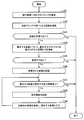
- FIG. 16 is a flowchart showing an example of analysis of variables based on logs. In the following, the process illustrated in FIG. 16 will be described in order of step number. The process shown below corresponds to step S24 in FIG.
- the verification unit 140 refers to the log table 116 to search for a block that has output result data having contents different from the old result data. For example, the verification unit 140 can acquire the block ID “3” of the block that has output the result data “hosts” file from the log table 116.
- the verification unit 140 refers to the free variable table 114 and searches for a variable used in the searched block. For example, for the block with the block ID “3”, the verification unit 140 can obtain the variables W and X used in the block from the free variable table 114.
- the verification unit 140 determines whether or not any variable used in the corresponding block has been acquired as a result of the search in step S32. If acquired, the process proceeds to step S34. If it cannot be obtained, the process ends.
- the case where the variable cannot be acquired is a case where a free variable set corresponding to the corresponding block is not set in the free variable table 114 (“ ⁇ ”).
- the processes in subsequent steps S34 to S40 are executed for each variable (for example, the process for variable X is executed after the process for variable W is executed). Etc.).
- the verification unit 140 refers to the log table 116, and changes the target variable (any variable acquired by the search in step S32) from the log before the target block (“ ⁇ variable”). Name> changed ”). For example, in the case of the variable W, there is no change log in the log before the block of interest (the block with the block ID “3”). In the case of the variable X, the change log “X changed” exists in the log before the target block.
- step S35 The verification unit 140 determines whether there is a change log for the variable of interest. If there is a change log, the process proceeds to step S36. If there is no change log, the process ends. For example, if there is a variable W, there is no change log as described above, and the process related to the variable W ends. If there is a variable X, the process proceeds to step S36 because there is a change log as described above.
- the verification unit 140 records the variable of interest in the storage unit 110 as a variable whose assignment value has been changed.
- the verification unit 140 refers to the log table 116 and determines whether there is another variable on which the variable of interest depends. If there are other dependent variables, the process proceeds to step S38. If there are no other dependent variables, the process ends. If the description of “use ⁇ other variable name>” is included in the change log of the target variable, the verification unit 140 can determine that there is another variable on which the target variable depends. For example, since the log table 116 includes the description “Z changed: use X” for the variable Z, if the variable of interest is Z, the variable X is specified as another variable on which the variable Z depends. it can. If the description is not included, it can be determined that there is no other variable on which the variable of interest depends.
- the verification unit 140 records the dependency relationship between the variable of interest and other variables in the storage unit 110.
- the verification unit 140 refers to the log table 116 and searches for another variable on which the variable depends from a location before the change log of the variable of interest. The verification unit 140 switches the other variable to a variable of interest. Then, the process proceeds to step S37.
- the verification unit 140 records the variable in which the input content is changed and the dependency relationship between the variables in the storage unit 110.
- the verification unit 140 can record the variable dependency using the graph structure.
- the verification unit 140 can also present a dependency relationship between variables that has caused a difference in result data to the user.
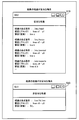
- FIG. 17 is a diagram illustrating an output example (part 1) of the verification result.
- a GUI (Graphical User Interface) 510 is an output example of step S26 in FIG.
- the GUI 520 is an output example of step S27 in FIG.
- the GUIs 510 and 520 are generated by the verification unit 140 and displayed on the display 11.
- the verification unit 140 can present the verification result of the deployment program 112 to the user through the GUIs 510 and 520.
- the GUI 510 includes a list of result data for which it is determined that the difference from the old result data is appropriate.
- the display content includes a character string indicating that the difference is valid, a difference (result data), a block and a variable that cause the difference.
- the verification unit 140 presents information indicating the result data (for example, “/ etc / hosts”) as a portion having a difference.
- a device file for example, “/ dev / hda0” or another type of file name may be presented.
- the verification unit 140 presents a description location in the deployment program 112 of the block that caused the difference. Specifically, the line number in the deployment program 112 corresponding to the description location of the block (for example, “lines x2-y2”) is presented. For example, in the post-conversion deployment program 113, “log_write (“ block ⁇ block ID> enter ”)” is inserted in which row of the deployment program 112 in the post-conversion deployment program 113. Can be understood.
- the verification unit 140 presents a description location (for example, an assignment expression or a location in a block) in the deployment program 112 of the variable that has caused the factor. Specifically, the line number in the deployment program 112 corresponding to the description part of the variable (for example, “line b”) is presented.
- the GUI 520 includes a list of result data that is determined to be invalid from the old result data.
- the display content includes a character string indicating that the difference is invalid, a portion having a difference (result data), a block and a variable that cause the difference.
- the verification unit 140 presents information indicating result data (for example, “/ usr / lib / xxx”) as a portion having a difference.
- the verification unit 140 presents the description location in the deployment program 112 of the block that caused the difference.
- a specific presentation method is the same as that of the GUI 510.
- the verification unit 140 does not present the variable that caused the difference in the GUI 520. This is because it is determined that there is no change in the input contents for the variable when the difference in the results is invalid. Therefore, in this case, the user can determine that the idempotency of the deployment program 112 is lost due to the processing of the block itself.
- FIG. 18 is a diagram showing an output example (part 2) of the verification result.
- the GUI 511 shows the relationship between factors that differ in “/ etc / exports” from the old result data (for example, “/ etc / exports” obtained at the previous deployment).
- the verification unit 140 may be operated by a user at a different location (“/ etc / exports”), a block location (“lines x4-y4”) or a variable location (“lines d, b”) displayed on the GUI 510. Accept selection input. Then, the verification unit 140 generates a GUI 511 according to the selected location and displays the GUI 511 on the display 11. The user can perform the selection input using the input device 12, for example.
- the relationship between each factor is shown by connecting the difference part, the block, the variable Z, and the variable X with a relation line.
- the verification unit 140 can present the relationship between the variable Z and the variable X to the user based on the dependency relationship between the variables recorded in steps S37 to S39 in FIG.
- the GUI 521 indicates the relationship between each factor that “/ usr / lib / xxx” is different from the old result data (for example, “/ usr / lib / xxx” obtained at the previous deployment).
- the verification unit 140 accepts a selection input by the user of a different location (“/ usr / lib / xxx”) or a block location (“lines x5-y5”) displayed on the GUI 520. Then, the verification unit 140 generates a GUI 521 according to the selected location and displays the GUI 521 on the display 11. For example, in the GUI 520, the relationship between the factors is indicated by connecting the different portions and the blocks with a relationship line.
- FIG. 19 is a diagram illustrating an output example (part 3) of the verification result.
- the GUI 512 is another output example showing the relationship between factors different from the old result data of “/ etc / exports”. For example, if the block with the block ID “5” also uses a variable other than the variable Z described above, the system of the variable Z and the system of the other variable are separated as the system of variables related to the block. Can also be presented to the user.
- the deployment program is also maintained in accordance with the specification change such as the setting change of the virtual machine itself and the addition / change of the software to be executed.
- the deployment program some parameters such as addition of a user account may be changed.
- the description of the block itself may be changed with the addition of software or setting contents.
- the problem is how to verify the validity (in this example, idempotent) of each result data generated by each block.
- the result data is different from the old result data, it is necessary to know from the result data only whether the cause of the difference is a change in the setting values of some variables or the processing of any block itself. Because it is difficult.
- the deployment server 100 generates a post-conversion deployment program 113 from the deployment program 112.
- the deployment server 100 performs deployment using the post-conversion deployment program 113 instead of the deployment program 112, thereby causing the deployment destination server 200 to output a log for identifying changes in input contents and blocks. Then, if the result data is different from the old result data, the block that outputs the result data and the variable used for the block are identified from the log, and by confirming whether there is a change in the input content for the variable, The validity of the difference is evaluated and presented to the user.
- the difference point presented in the GUI 510 is a reasonable difference point according to the input content for the variable. For this reason, the user can determine that the priority of review of the block presented in the GUI 510 is lowered. Alternatively, the user may determine not to review the block presented on the GUI 510.
- the difference point presented in the GUI 520 is an invalid difference point that is not caused by the input content for the variable. For this reason, the user can determine that the priority of review of the block presented in the GUI 520 is increased. At that time, by referring to the GUI 520, the description location of the target block in the deployment program 112 can be easily grasped, and the work can be started quickly.
- the description of the block itself may be changed.
- the deployment server 100 may generate the post-conversion deployment program 113 so that a change in the description of the block itself can be acquired as the system call log 115.
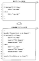
- FIG. 20 is a diagram showing another example of the deployment program.
- the deployment program 112a shows another example of a change by the user with respect to the old deployment program 111.
- the description of the ninth line of the old deployment program 111 has been changed to “execute“ pvcreate # ⁇ DISK ⁇ ”do command“ pvcreate --uuid # ⁇ node ⁇ 'uuid' ⁇ # ⁇ DISK ⁇ ”in the deployment program 112a. ing.
- the program conversion unit 120 may generate the post-conversion deployment program 113 so that the system call log 115 can acquire that the block (for example, the block with the block ID “1”) is changed. Specifically, the program conversion unit 120 compares the blocks (for example, the disk setting part B1) in which the same setting of the old deployment program 111 and the deployment program 112 is performed. When it is detected that there is a difference in the code of the block, a description such as “log_write (“ block changed ”)” is inserted immediately before the description of “log_write (“ block 1 enter ”).” For example, the program conversion unit 120. This process can be added to step S19 of FIG.
- the system call log 115 acquired by the deployment execution unit 130 from the deployment destination server 200 also describes that the block is changed.
- the log table 116 generated by the verification unit 140 the fact that the block is changed is also registered. Specifically, according to the above example, “log changed” is registered immediately before “block 1 enter”, and the log table 116 indicates that the code of the block itself having the block ID “1” has changed. It becomes possible to grasp. For example, these processes by the deployment execution unit 130 and the verification unit 140 can be added to steps S3 and S4 in FIG.
- the verification unit 140 adds “whether or not the input contents of the variable used in the block that output the result data has changed” to “ The validity can be judged based on whether or not the code has changed. For example, in the verification of idempotency, when result data different from the old result data is obtained, the following criteria can be set for the validity of the difference.
- step S25 in FIG. 15 the determination by the verification unit 140 in step S25 in FIG. 15 is performed based on the log table 116 (the block code change is registered) (the block in which the result data extracted in step S23 is output). Is replaced with determination of which of the above (1) to (4) is satisfied. If the conditions correspond to (1) to (3), the process proceeds to step S26. If it corresponds to (4), the process proceeds to step S27. However, in the case of corresponding to (2), it is not necessary to output the variable part as a factor in Step S26 (because there is no change in the input contents). In this way, it is possible to further save labor for the program verification work by the user.
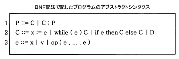
- FIG. 21 is a diagram showing an example of a program written in BNF notation.
- P on the first line represents a program.
- C represents one of assignment, a while statement, an if statement, and a block.
- E on the second line represents an expression.
- D represents a block for deployment (for example, a block for each function such as account setting).
- V represents a value such as a number or a character string.
- FIG. 22 is a diagram showing a description example (part 1) of a function for program conversion.
- a variable changed_var representing a set of variables whose input contents have been changed is first declared to be an empty set.
- the addition of an element to changed_var is performed using the function changed_var. It shall be executed with add.
- the function changed_var. is used to determine whether there is a list element in the changed_var. It is assumed to be included.
- the program 610 is a description example of a function vars that extracts a variable from the syntax of the deployment program 112 (or the deployment program 112a, and so on) and creates a list of variables.
- the program 620 is a description example of the function V that generates a character string indicating the dependency relationship between variables.
- the notation “V (e)” indicates that the function “V” takes the program “e” as an argument.
- FIG. 23 is a diagram showing a description example (part 2) of the function for program conversion.
- the program 630 is a description example of the function T that converts the deployment program 112.
- the function T of the program 630 displays a log indicating the change when the part to be assigned is changed between the old deployment program 111 and the deployment program 112 and when the code of each block itself is changed.
- the deployment program 112 is converted to output.
- the function changecheck is a function for confirming whether or not “C” is a changed part.
- the function S is a function for detecting a place where it is considered that the input to the variable is likely to be changed, and converting the deployment program 112 so as to output a log indicating the change for the place.
- the place where the possibility that the input to the variable has been changed is a place where the variable is defined using a while sentence or an if sentence. This is because in an if statement and a while statement, there is a high possibility that the value assigned to a variable will change if the condition changes.
- FIG. 24 is a diagram illustrating a description example (part 3) of the function for program conversion.
- the program 640 is a description example of the function S.
- the function S records the possibility of changing the assigned value regardless of the change of the assigned value when the conditional expression of the if statement or the while statement is changed and the assigned location to the variable may be changed. It is what you want to do. In other words, even if the assignment statement for the variable does not change the input value or the expression itself, the assignment value may be changed depending on the condition.
- the value assigned to the variable may change due to the different number of repetitions.
- the clause to be executed may change from the “then” clause to the else clause, and the assignment statement to the variable to be executed may change.
- the variables defined in the while statement and if statement it is considered that there is a high possibility that it has been changed, and the fact that the input content has been changed (may have been changed) is output to the log. To do.
- the assignment statement is clearly changed or the input is changed, that fact is output to a log so that it can be distinguished from a mere possibility.
- FIG. 25 is a diagram showing another conversion example of the deployment program.
- the post-conversion deployment program 113a illustrates the result of conversion of the deployment program 112b using the function T.
- log_write ("DISK changed;”) "is inserted respectively.
- the inserted description corresponds to the fifth and ninth lines of the post-conversion deployment program 113a.
- the program conversion unit 120 may perform such conversion in step S1 of FIG. Thereby, it is possible to record in the system call log 115 that the variable DISK is highly likely to be changed.
- FIG. 26 is a diagram illustrating an example of a log output format.
- the log format 650 shows the log grammar in BNF notation.
- a log is a list arranged in the order in which it occurred.
- “X” on the third line represents a program variable.
- “ID” represents a block ID.
- ADD_LIST indicates that the input content for the variable X has been changed.
- “ADD_LIST” indicates the changed input (dependent variable). For example, if “ADD_LIST” is “use Y; use Z;”, variables Y and Z are used as the value to be assigned to variable X, such as “Y + Z” (variable X depends on variables Y and Z). Show).
- block ID enter indicates the start of processing of the block indicated by “ID”.
- Block changed; block ID enter indicates that the code of the block indicated by “ID” has been changed and the start of processing of the block.
- Block ID exit indicates the end of processing of the block indicated by “ID”.
- the deployment server 100 can generate a post-conversion deployment program using the functions illustrated in FIGS.
- the deployment server 100 performs deployment using the post-conversion deployment program, thereby allowing the deployment destination server 200 to output the system call log 115 including the log indicated by the log format 650 and using the system call log 115 for verification of the deployment program.
- the verification method using the system call log 115 (and the log table 116) is as described above.
- the information processing of the first embodiment can be realized by causing the computing unit 1b to execute a program.
- the information processing according to the second embodiment can be realized by causing the processor 101 to execute a program.
- the program can be recorded on a computer-readable recording medium (for example, the optical disc 13, the memory device 14, and the memory card 16).
- the program can be distributed by distributing a recording medium on which the program is recorded.
- the program may be stored in another computer and distributed via a network.
- the computer may store (install) a program recorded on a recording medium or a program received from another computer in a storage device such as the RAM 102 or the HDD 103, and read and execute the program from the storage device. .
Landscapes
- Engineering & Computer Science (AREA)
- Theoretical Computer Science (AREA)
- General Engineering & Computer Science (AREA)
- Physics & Mathematics (AREA)
- General Physics & Mathematics (AREA)
- Quality & Reliability (AREA)
- Computer Hardware Design (AREA)
- Computing Systems (AREA)
- Health & Medical Sciences (AREA)
- Biomedical Technology (AREA)
- Software Systems (AREA)
- Mathematical Physics (AREA)
- Debugging And Monitoring (AREA)
Abstract
La présente invention a pour objectif d'aider à comprendre correctement un facteur où des résultats d'exécution diffèrent. Lors de l'exécution d'un programme (2), une unité de calcul (1b) acquiert un journal (3) comprenant des informations qui identifient des variables (A, C) dont le contenu d'entrée a subi un changement par rapport à une précédente exécution, et des informations qui indiquent une correspondance entre des éléments de programme (2a, 2b, 2c) et chaque résultat d'exécution émis par chacun desdits éléments de programme. Si l'un des résultats de l'exécution du programme (2) diffère du résultat de la précédente exécution de ce programme, l'unité de calcul (1b) interroge le journal (3) et recherche l'élément de programme (2a) qui correspond audit résultat de l'exécution et la variable (A) qui est utilisée par l'élément de programme (2a). Sur la base des circonstances de changement du contenu d'entrée par rapport à la variable (A), l'unité de calcul (1b) évalue le facteur où le résultat de l'exécution diffère, ainsi que la validité de la différence. L'unité de calcul (1b) émet des informations indiquant le site où les résultats de l'exécution diffèrent, le facteur de la différence et la validité de la différence.
Priority Applications (3)
| Application Number | Priority Date | Filing Date | Title |
|---|---|---|---|
| JP2015530653A JP6070847B2 (ja) | 2013-08-09 | 2013-08-09 | 検証方法、検証装置および検証プログラム |
| PCT/JP2013/071724 WO2015019504A1 (fr) | 2013-08-09 | 2013-08-09 | Procédé de vérification, dispositif de vérification et programme de vérification |
| US14/990,935 US20160124795A1 (en) | 2013-08-09 | 2016-01-08 | Evaluation method and apparatus |
Applications Claiming Priority (1)
| Application Number | Priority Date | Filing Date | Title |
|---|---|---|---|
| PCT/JP2013/071724 WO2015019504A1 (fr) | 2013-08-09 | 2013-08-09 | Procédé de vérification, dispositif de vérification et programme de vérification |
Related Child Applications (1)
| Application Number | Title | Priority Date | Filing Date |
|---|---|---|---|
| US14/990,935 Continuation US20160124795A1 (en) | 2013-08-09 | 2016-01-08 | Evaluation method and apparatus |
Publications (1)
| Publication Number | Publication Date |
|---|---|
| WO2015019504A1 true WO2015019504A1 (fr) | 2015-02-12 |
Family
ID=52460870
Family Applications (1)
| Application Number | Title | Priority Date | Filing Date |
|---|---|---|---|
| PCT/JP2013/071724 Ceased WO2015019504A1 (fr) | 2013-08-09 | 2013-08-09 | Procédé de vérification, dispositif de vérification et programme de vérification |
Country Status (3)
| Country | Link |
|---|---|
| US (1) | US20160124795A1 (fr) |
| JP (1) | JP6070847B2 (fr) |
| WO (1) | WO2015019504A1 (fr) |
Cited By (3)
| Publication number | Priority date | Publication date | Assignee | Title |
|---|---|---|---|---|
| JP2016167180A (ja) * | 2015-03-10 | 2016-09-15 | 日本電気株式会社 | デバッグ支援装置、デバッグ支援システム、デバッグ支援方法、および、デバッグ支援プログラム |
| CN108304311A (zh) * | 2015-06-26 | 2018-07-20 | 中兴通讯股份有限公司 | 一种日志信息检测方法及装置 |
| WO2024176321A1 (fr) * | 2023-02-20 | 2024-08-29 | 日本電信電話株式会社 | Dispositif de gestion, procédé de gestion et programme de gestion |
Families Citing this family (7)
| Publication number | Priority date | Publication date | Assignee | Title |
|---|---|---|---|---|
| US10180872B2 (en) * | 2016-04-14 | 2019-01-15 | Vmware, Inc. | Methods and systems that identify problems in applications |
| US11580186B2 (en) * | 2016-06-14 | 2023-02-14 | Google Llc | Reducing latency of digital content delivery over a network |
| JP6407919B2 (ja) * | 2016-06-15 | 2018-10-17 | ファナック株式会社 | 数値制御装置および変数判定方法 |
| CN109857431B (zh) * | 2019-01-11 | 2022-06-03 | 平安科技(深圳)有限公司 | 代码修改方法及装置、计算机可读介质及电子设备 |
| US11023358B2 (en) | 2019-07-19 | 2021-06-01 | Vmware, Inc. | Review process for evaluating changes to target code for a software-based product |
| JP2021149610A (ja) * | 2020-03-19 | 2021-09-27 | キヤノン株式会社 | 情報処理装置、情報処理方法、および物品の製造方法 |
| JP7631667B2 (ja) * | 2020-03-23 | 2025-02-19 | カシオ計算機株式会社 | 情報処理装置、検査方法、検査プログラム、およびサーバ |
Citations (1)
| Publication number | Priority date | Publication date | Assignee | Title |
|---|---|---|---|---|
| JPH10320234A (ja) * | 1997-05-21 | 1998-12-04 | Hitachi Ltd | ソフトウェアの自動テスト方法 |
Family Cites Families (5)
| Publication number | Priority date | Publication date | Assignee | Title |
|---|---|---|---|---|
| DE69432974T2 (de) * | 1993-05-10 | 2004-05-27 | Thinking Software, Inc., Cupertino | Verfahren und vorrichtung zur automatischen analyse eines zielprogramms |
| US8234256B2 (en) * | 2003-11-26 | 2012-07-31 | Loglogic, Inc. | System and method for parsing, summarizing and reporting log data |
| US7698305B2 (en) * | 2006-12-01 | 2010-04-13 | Microsoft Corporation | Program modification and loading times in computing devices |
| US8694966B2 (en) * | 2010-03-04 | 2014-04-08 | Oracle International Corporation | Identifying test cases to be run after changes to modules of a software application |
| US9092568B2 (en) * | 2012-04-30 | 2015-07-28 | Nec Laboratories America, Inc. | Method and system for correlated tracing with automated multi-layer function instrumentation localization |
-
2013
- 2013-08-09 WO PCT/JP2013/071724 patent/WO2015019504A1/fr not_active Ceased
- 2013-08-09 JP JP2015530653A patent/JP6070847B2/ja not_active Expired - Fee Related
-
2016
- 2016-01-08 US US14/990,935 patent/US20160124795A1/en not_active Abandoned
Patent Citations (1)
| Publication number | Priority date | Publication date | Assignee | Title |
|---|---|---|---|---|
| JPH10320234A (ja) * | 1997-05-21 | 1998-12-04 | Hitachi Ltd | ソフトウェアの自動テスト方法 |
Cited By (3)
| Publication number | Priority date | Publication date | Assignee | Title |
|---|---|---|---|---|
| JP2016167180A (ja) * | 2015-03-10 | 2016-09-15 | 日本電気株式会社 | デバッグ支援装置、デバッグ支援システム、デバッグ支援方法、および、デバッグ支援プログラム |
| CN108304311A (zh) * | 2015-06-26 | 2018-07-20 | 中兴通讯股份有限公司 | 一种日志信息检测方法及装置 |
| WO2024176321A1 (fr) * | 2023-02-20 | 2024-08-29 | 日本電信電話株式会社 | Dispositif de gestion, procédé de gestion et programme de gestion |
Also Published As
| Publication number | Publication date |
|---|---|
| JPWO2015019504A1 (ja) | 2017-03-02 |
| JP6070847B2 (ja) | 2017-02-01 |
| US20160124795A1 (en) | 2016-05-05 |
Similar Documents
| Publication | Publication Date | Title |
|---|---|---|
| JP6070847B2 (ja) | 検証方法、検証装置および検証プログラム | |
| US8930884B2 (en) | Efficient extraction of software dependencies from program code | |
| CN106559438B (zh) | 一种基于目标网络平台的程序上传方法和装置 | |
| CN109564540B (zh) | 用于jit编译器的调试的系统、方法和设备 | |
| US7996816B2 (en) | Method and apparatus for dynamically binding service component implementations for specific unit test cases | |
| KR20060070412A (ko) | 소프트웨어 셋업을 위한 언어-중립 및 언어-특정 설치패키지 | |
| JP2019053729A (ja) | スマートコントラクトのテスト方法及びテスト装置 | |
| CN108241720B (zh) | 数据处理方法、装置和计算机可读存储介质 | |
| CN103180834B (zh) | 自动操作系统测试框架 | |
| JP4395761B2 (ja) | プログラムテスト支援装置およびその方法 | |
| US7958422B2 (en) | Method and apparatus for generating self-verifying device scenario code | |
| US8434072B2 (en) | Automatic retrieval of translated messages for interacting with legacy systems | |
| CN117215965B (zh) | 基于测试用例识别的测试方法、装置、电子设备和介质 | |
| JP2023146844A (ja) | 生成プログラム、生成方法および情報処理装置 | |
| US7100039B2 (en) | Systems and methods for a bootstrap mechanism for software execution | |
| US20160253157A1 (en) | Software refactoring | |
| CN107077365A (zh) | 有选择地加载预编译的头部和/或其部分 | |
| CN114064474A (zh) | 测试方法、装置、电子设备及计算机可读存储介质 | |
| JP2009193488A (ja) | ソフトウェアテスト項目編集支援装置およびソフトウェアテスト項目編集支援方法 | |
| JP7318704B2 (ja) | テスト装置、テスト方法及びプログラム | |
| CN115469844A (zh) | 代码处理方法、系统、计算机集群、介质及程序产品 | |
| JP2008293382A (ja) | テスト仕様自動生成方式 | |
| JP6397800B2 (ja) | テスト支援システムおよびテスト支援方法 | |
| US10776255B1 (en) | Automatic verification of optimization of high level constructs using test vectors | |
| JP6770335B2 (ja) | 解析装置及びプログラム |
Legal Events
| Date | Code | Title | Description |
|---|---|---|---|
| 121 | Ep: the epo has been informed by wipo that ep was designated in this application |
Ref document number: 13891209 Country of ref document: EP Kind code of ref document: A1 |
|
| ENP | Entry into the national phase |
Ref document number: 2015530653 Country of ref document: JP Kind code of ref document: A |
|
| NENP | Non-entry into the national phase |
Ref country code: DE |
|
| 122 | Ep: pct application non-entry in european phase |
Ref document number: 13891209 Country of ref document: EP Kind code of ref document: A1 |