WO2015019529A1 - 透明積層体、及びそれを用いた保護具 - Google Patents
透明積層体、及びそれを用いた保護具 Download PDFInfo
- Publication number
- WO2015019529A1 WO2015019529A1 PCT/JP2014/002980 JP2014002980W WO2015019529A1 WO 2015019529 A1 WO2015019529 A1 WO 2015019529A1 JP 2014002980 W JP2014002980 W JP 2014002980W WO 2015019529 A1 WO2015019529 A1 WO 2015019529A1
- Authority
- WO
- WIPO (PCT)
- Prior art keywords
- film
- adhesive
- transparent
- transparent laminate
- laminated
- Prior art date
- Legal status (The legal status is an assumption and is not a legal conclusion. Google has not performed a legal analysis and makes no representation as to the accuracy of the status listed.)
- Ceased
Links
Images





Classifications
-
- B—PERFORMING OPERATIONS; TRANSPORTING
- B32—LAYERED PRODUCTS
- B32B—LAYERED PRODUCTS, i.e. PRODUCTS BUILT-UP OF STRATA OF FLAT OR NON-FLAT, e.g. CELLULAR OR HONEYCOMB, FORM
- B32B7/00—Layered products characterised by the relation between layers; Layered products characterised by the relative orientation of features between layers, or by the relative values of a measurable parameter between layers, i.e. products comprising layers having different physical, chemical or physicochemical properties; Layered products characterised by the interconnection of layers
- B32B7/04—Interconnection of layers
- B32B7/06—Interconnection of layers permitting easy separation
-
- B—PERFORMING OPERATIONS; TRANSPORTING
- B32—LAYERED PRODUCTS
- B32B—LAYERED PRODUCTS, i.e. PRODUCTS BUILT-UP OF STRATA OF FLAT OR NON-FLAT, e.g. CELLULAR OR HONEYCOMB, FORM
- B32B3/00—Layered products comprising a layer with external or internal discontinuities or unevennesses, or a layer of non-planar shape; Layered products comprising a layer having particular features of form
- B32B3/26—Layered products comprising a layer with external or internal discontinuities or unevennesses, or a layer of non-planar shape; Layered products comprising a layer having particular features of form characterised by a particular shape of the outline of the cross-section of a continuous layer; characterised by a layer with cavities or internal voids ; characterised by an apertured layer
- B32B3/30—Layered products comprising a layer with external or internal discontinuities or unevennesses, or a layer of non-planar shape; Layered products comprising a layer having particular features of form characterised by a particular shape of the outline of the cross-section of a continuous layer; characterised by a layer with cavities or internal voids ; characterised by an apertured layer characterised by a layer formed with recesses or projections, e.g. hollows, grooves, protuberances, ribs
-
- A—HUMAN NECESSITIES
- A42—HEADWEAR
- A42B—HATS; HEAD COVERINGS
- A42B3/00—Helmets; Helmet covers ; Other protective head coverings
- A42B3/04—Parts, details or accessories of helmets
- A42B3/18—Face protection devices
- A42B3/22—Visors
-
- B—PERFORMING OPERATIONS; TRANSPORTING
- B32—LAYERED PRODUCTS
- B32B—LAYERED PRODUCTS, i.e. PRODUCTS BUILT-UP OF STRATA OF FLAT OR NON-FLAT, e.g. CELLULAR OR HONEYCOMB, FORM
- B32B7/00—Layered products characterised by the relation between layers; Layered products characterised by the relative orientation of features between layers, or by the relative values of a measurable parameter between layers, i.e. products comprising layers having different physical, chemical or physicochemical properties; Layered products characterised by the interconnection of layers
- B32B7/04—Interconnection of layers
- B32B7/12—Interconnection of layers using interposed adhesives or interposed materials with bonding properties
-
- G—PHYSICS
- G02—OPTICS
- G02B—OPTICAL ELEMENTS, SYSTEMS OR APPARATUS
- G02B1/00—Optical elements characterised by the material of which they are made; Optical coatings for optical elements
- G02B1/10—Optical coatings produced by application to, or surface treatment of, optical elements
- G02B1/11—Anti-reflection coatings
- G02B1/118—Anti-reflection coatings having sub-optical wavelength surface structures designed to provide an enhanced transmittance, e.g. moth-eye structures
-
- B—PERFORMING OPERATIONS; TRANSPORTING
- B32—LAYERED PRODUCTS
- B32B—LAYERED PRODUCTS, i.e. PRODUCTS BUILT-UP OF STRATA OF FLAT OR NON-FLAT, e.g. CELLULAR OR HONEYCOMB, FORM
- B32B2307/00—Properties of the layers or laminate
- B32B2307/40—Properties of the layers or laminate having particular optical properties
- B32B2307/412—Transparent
-
- B—PERFORMING OPERATIONS; TRANSPORTING
- B32—LAYERED PRODUCTS
- B32B—LAYERED PRODUCTS, i.e. PRODUCTS BUILT-UP OF STRATA OF FLAT OR NON-FLAT, e.g. CELLULAR OR HONEYCOMB, FORM
- B32B2437/00—Clothing
- B32B2437/04—Caps, helmets
-
- B—PERFORMING OPERATIONS; TRANSPORTING
- B32—LAYERED PRODUCTS
- B32B—LAYERED PRODUCTS, i.e. PRODUCTS BUILT-UP OF STRATA OF FLAT OR NON-FLAT, e.g. CELLULAR OR HONEYCOMB, FORM
- B32B2571/00—Protective equipment
Definitions
- the present invention provides, for example, a film-like member in which a plurality of structures are provided on at least one surface of a flexible substrate at a pitch equal to or less than the wavelength of visible light, between at least a part of the area of the film-like member. It is related with the transparent laminated body characterized by laminating
- shields of helmets used for auto racing of two-wheeled vehicles and four-wheeled vehicles often get dirty because the surface becomes dirty in a short time.
- the protective glasses for painting used in the painting operation may be obstructed by the surface of the glasses being stained with paint or the like scattered during the painting operation.
- the surface of medical goggles or face shields may be contaminated with blood scattered from the patient during the operation.
- Patent Document 1 discloses a protection device for a shield portion of a helmet in which a plurality of sheet-like protective covers, that is, disposable visors are attached so as to cover the shield portion of the helmet.
- the protective device is a simple protective film laminated structure as described above, reflection occurs at the interface between the laminated layers.
- the permeability is simply lowered as the number of stacked layers increases (the number of stacked layers can be limited).
- a transparent plastic film can be used as the above-described protective film.
- a film having a refractive index of 1.4 to 1.6 is widely used, and there is reflection of about 4 to 5% on the front and back of the film, respectively, and the total transmittance is 90 to 92. %.
- One film has a transmittance of about 90%, but when two sheets are stacked, it is 81%, and when three sheets are stacked, 73%. is there.
- optical elements and films having a moth-eye structure having a pitch equal to or smaller than the visible light wavelength are widely known.
- Patent Document 2 as a method of providing a moth-eye structure on a transparent substrate, an uncured ultraviolet curable resin is sandwiched between masters having a structure shape on the surface, and light irradiation is performed. There is a technique to get it.
- such a moth-eye structure is basically compatible with all wavelengths. Therefore, when the subject is viewed through the moth-eye structure, the color tone There are also advantages such as no change.
- Patent Document 3 discloses a low-reflection transparent plate in which a low reflectance is realized by the moth-eye effect in which the fine structure of the surface is expressed, and an exhibition case using the same. Has been.
- Patent Document 2 when a moth-eye structure is obtained with an ultraviolet curable resin, the optical performance may be degraded due to friction of the structure due to the nature of the resin. . Therefore, assuming application to a shield, goggles, protective glasses, etc. of a helmet, it is not desirable to wipe off dirt that obstructs visual recognition on the surface.
- a plurality of protective films having a moth-eye structure on one surface of the substrate are laminated to form a transparent laminate.
- the visibility is hindered by dirt, it is conceivable to remove the uppermost protective film together with the dirt to restore the visibility.
- the entire surface of the moth-eye structure of the protective film is bonded, it is not desirable from the viewpoints of immediateness and ease of peeling. Furthermore, distortion due to the thickness of the adhesive may also occur.
- the present invention was made in view of the technical problems as described above, and by laminating a film-like member provided with a moth-eye structure, while preventing an increase in reflectance and a decrease in transmittance, Immediate peeling and simplicity are not impaired, and the adhesive area is improved by limiting the adhesive area, for example by narrow width, avoiding distortion due to adhesive thickness, and ensuring visibility
- An object of the present invention is to provide a transparent laminate and a protective device using the same.
- the transparent laminate according to the first aspect of the present invention is provided with at least one surface of a substrate having a structure with irregularities having a pitch of visible light wavelength or less.
- a plurality of film-like members are provided, and at least end portions of the film-like members are laminated via an adhesive layer, and there is a gap between the above-mentioned structures facing each other between the laminated film-like members.
- such a transparent laminate is provided at the visual recognition site.
- the transparent laminate according to the present invention by laminating a film-like member provided with a moth-eye structure, while preventing an increase in reflectance and a decrease in transmittance, Immediate peeling and simplicity are not impaired, the releasability of the adhesive is improved, the occurrence of distortion due to the thickness of the adhesive is avoided, and visibility can be ensured.
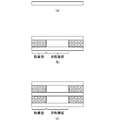
- or (c) are the block diagrams of the transparent laminated body which concerns on Example 1 of this invention.
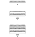
- or (c) are the block diagrams of the transparent laminated body which concerns on Example 2 of this invention.
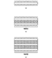
- or (c) are the block diagrams of the transparent laminated body which concerns on the comparative example 1 of this invention. It is a figure which shows the evaluation result of the transmittance
- FIG. 1 A thru
- or (c) is another structure of the transparent laminated body which is a laminated body through the adhesion layer of the film-like member provided with the moth-eye shape on both surfaces produced by the method similar to Example 1 of this invention.
- FIG. 1 A thru
- the transparent laminated body of this invention and a protective device using the same are not limited to the following description, In the range which does not deviate from the summary of this invention, it can change suitably.
- the transparent laminate of the present invention will be briefly described. Structures are provided on the front and back surfaces of a flexible substrate with a pitch of a visible light wavelength or less.
- a fine concavo-convex structure having an antireflection function is referred to as a “moth eye structure”.
- the adhesive region of the adhesive layer of the film-like member can be set as appropriate. For example, there is an aspect in which an adhesive layer is provided only at the end, and this adhesive layer may be formed by lines or dots. Also, both may be provided.
- the adhesive layer does not exclude an aspect provided not only at the end portion of the film member but also over the entire surface.
- the peelability may be different between the end portion and the region outside the end portion. Desirably, the peelability other than the end is required to be weaker than the end.
- the end portion of the film-like member or a part thereof can be physically fixed and laminated.
- the film-like member in the state where the film-like member is laminated, the film-like member is fixed by a pin, or is fixed by being hooked on a fixed pin or hook.
- the fixing portion provided at the end portion or a part thereof is required to be provided so that the laminate is stable.
- a part of the film-like member may be processed such as cutting.
- the laminate may be fixed using an ultrasonic welding method or a thermal welding method.
- a film-like member having a moth-eye structure is laminated.
- the laminated structure of the film-like member in which the moth-eye structure is provided only on one side problems such as a decrease in transmittance and reflection on the back side of the film-like member occur, so the moth-eye structure is provided on both sides.
- a transparent laminate is formed using the film-like member.
- ⁇ ⁇ Lamination is facilitated by an adhesive layer such as an adhesive. It is desirable that this adhesive is provided on the outer periphery so that it is out of view when mounted.
- an adhesive layer such as an adhesive. It is desirable that this adhesive is provided on the outer periphery so that it is out of view when mounted.
- FIG. 1 is a schematic view showing an example of the configuration of a transparent laminate according to an embodiment of the present invention.
- the transparent laminate 1 is configured by bonding a film-like member 10 as a plurality of optical elements with an adhesive layer 2 made of an adhesive or the like.
- Each film-like member 10 is provided with a structure 12 on both sides of a base 11 with a base layer 13 interposed.
- the film-like member 10 as an optical element has an antireflection function on both the front and back surfaces.
- the film-like member 10 includes a base body 11 having a front surface and a back surface, a base layer 13 laminated on the front surface and the back surface of the base body 11, and a plurality of structures 12 provided via the base layer 13.
- the plurality of structures 12 are regularly arranged in a plurality of rows on the base layer 13 on the front and back surfaces of the base body 11.
- the front and back surfaces of the film-like member 10 have a concavo-convex shape by a moth-eye structure composed of a plurality of structures 12 (however, the structure 12 can be provided only on the surface).
- the front and back surfaces of the film-like member 10 are uneven surfaces formed by a moth-eye structure in which a plurality of structures are provided at a pitch equal to or smaller than the wavelength of visible light.
- optical adjustment function means an optical adjustment function of transmission characteristics and reflection characteristics.
- the film-like member 10 as an optical element has transparency with respect to visible light, for example, and the refractive index n is preferably 1.30 or more and 2.00 or less, more preferably 1.34 or more. It is preferably within the range of 00 or less. However, it is not limited to this.
- the refractive index of the structure 12 is preferably the same as or substantially the same as the refractive index of the adhesive layer 2 and the substrate 11. This is because the internal reflection can be suppressed and the contrast can be improved.
- FIG. 1 shows an example in which the structure 12 is formed on the front and back surfaces of the base 11 via the base layer 13.
- the base layer 13 plays a role of improving the adhesion of the structure 12 to the base 11. ing.
- the base layer 13 is an optical layer integrally formed with the structure 12 on the bottom surface side of the structure 12, has transparency, and has the same energy ray curable resin composition as the structure 12. It may be formed by curing an object or the like.
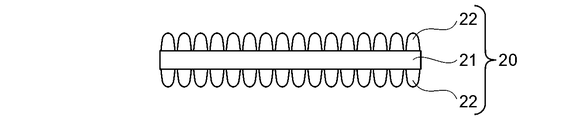
- a film-like member 20 that does not have the base layer 13 and in which the moth-eye structure of the plurality of structures 22 is directly formed on the base 21 may be used.
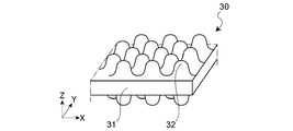
- the base body and the structure may be integrally formed as shown in FIG. 3, for example. That is, in the case of the configuration of FIG. 3, the structural body 32 is integrally formed on both surfaces of the base 31 to form the film-like member 30.
- the substrate 11 will be further described.
- the substrate 11 is a transparent substrate having transparency, for example.
- Examples of the material of the substrate 11 include those containing a plastic material having transparency as a main component, but are not particularly limited to these materials.
- an undercoat layer (not shown) may be further provided by surface treatment in order to further improve the surface energy, coatability, slipperiness, flatness, etc. of the surface of the plastic material.
- the undercoat layer include organoalkoxy metal compounds, polyesters, acrylic-modified polyesters, polyurethanes, and the like.
- the surface of the substrate 11 may be subjected to corona discharge treatment, UV irradiation treatment, or the like.
- the substrate 11 When the substrate 11 is a plastic film, the substrate 11 can be obtained by, for example, a method of stretching the above-mentioned resin or forming a film after being diluted with a solvent and drying.
- the thickness of the substrate 11 is preferably selected as appropriate according to the application of the optical laminate 1, and may be, for example, about 10 ⁇ m or more and 500 ⁇ m or less.
- Examples of the shape of the substrate 11 include a film shape and a plate shape, but are not particularly limited to these shapes.
- a sheet shall be contained in a film.
- Examples of the material of the substrate 11 include methyl methacrylate (co) polymer, polycarbonate, styrene (co) polymer, methyl methacrylate-styrene copolymer, cellulose diacetate, cellulose triacetate, cellulose acetate butyrate, polyester, Examples include, but are not limited to, polyamide, polyimide, polyether sulfone, polysulfone, polypropylene, polymethylpentene, polyvinyl chloride, polyvinyl acetal, polyether ketone, polyurethane, and glass.
- the wavelength band of visible light is 360 nm to 830 nm, but in this embodiment, the structures 12 are regularly arranged with a size equal to or smaller than the wavelength band of visible light. From this viewpoint, it is assumed that the arrangement pitch of the structures 12 does not exceed 350 nm.
- the structure 12 may have various shapes such as a cone shape, a column shape, and a needle shape.
- the structure 12 is formed by curing, for example, an energy ray curable resin composition.
- the energy beam curable resin product forming the structure 12 may have different physical properties on both surfaces of the substrate 11. For example, a function such as anti-fogging can be given to a specific surface by properly using water repellency and hydrophilicity depending on the intended use.
- an ultraviolet curable resin composition is preferably used.
- the energy beam curable resin composition may contain a filler, a functional additive, etc. as needed.
- the ultraviolet curable resin composition contains, for example, an acrylate and an initiator.
- the ultraviolet curable resin composition contains, for example, a monofunctional monomer, a bifunctional monomer, a polyfunctional monomer, and the like, and specifically, is a mixture of the following materials alone or in combination.
- examples of the “monofunctional monomer” include carboxylic acids (acrylic acid), hydroxys (2-hydroxyethyl acrylate, 2-hydroxypropyl acrylate, 4-hydroxybutyl acrylate), alkyl, alicyclics (isobutyl acrylate, t -Butyl acrylate, isooctyl acrylate, lauryl acrylate, stearyl acrylate, isobornyl acrylate, cyclohexyl acrylate), other functional monomers (2-methoxyethyl acrylate, methoxyethylene crycol acrylate, 2-ethoxyethyl acrylate, tetrahydrofurfuryl acrylate, Benzyl acrylate, ethyl carbitol acrylate, phenoxyethyl acrylate, N, N-dimethylaminoethyl acrylate N, N-dimethylaminopropylacrylamide, N, N-di
- bifunctional monomer examples include tri (propylene glycol) diacrylate, trimethylolpropane diallyl ether, urethane acrylate, and the like.
- polyfunctional monomer examples include trimethylolpropane triacrylate, dipentaerythritol penta and hexaacrylate, ditrimethylolpropane tetraacrylate, and the like.
- the “initiator” examples include 2,2-dimethoxy-1,2-diphenylethane-1-one, 1-hydroxy-cyclohexyl phenyl ketone, and 2-hydroxy-2-methyl-1-phenylpropan-1-one. And so on.
- the “filler” for example, both inorganic fine particles and organic fine particles can be used.
- the inorganic fine particles include metal oxide fine particles such as SiO 2 , TiO 2 , ZrO 2 , SnO 2 , and Al 2 O 3 .
- Examples of the “functional additive” include a leveling agent, a surface conditioner, and an antifoaming agent.
- the transparent laminate according to this embodiment includes a plurality of film-like members 10 in which a moth-eye structure composed of a structure 12 with irregularities having a pitch of a visible light wavelength or less is provided on the front and back surfaces of the base body 11, At least an end portion of the film-like member 10 is laminated by the adhesive layer 2 such as an adhesive, and there is a gap 14 between the structures 12 between the laminated film-like members 10.
- the adhesive layer 2 such as an adhesive
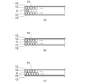
- FIGS. 4 (a) to 4 (c) The gap 14 includes a case where the gap 14 is formed of a resin such as an adhesive. That is, the air gap 14 may be an air layer or a resin layer.
- FIG. 4A shows a case where an air layer is formed without the opposing structures 12 contacting each other due to the thickness of the adhesive layer 2.
- FIG. 4B shows the case where the tips of the opposing structures 12 are in point contact with each other, but the structure 12 is a continuous concavo-convex structure, so that an air layer is formed in the recess.
- FIG. 4C shows a case where a predetermined air layer is formed because the front end of the structural body 12 enters the concave portion of the opposing structural body 12 but does not completely enter. In these cases, each air layer exists as a void. Note that the air gap is not limited to the air layer. For example, when the entire surface of the structure 12 is attached with the adhesive layer 2, the adhesive layer 2 may be included in the air gap in a broad sense.
- the structures 12 are in a regular arrangement, they have regularity when viewed in either the vertical direction or the horizontal direction, so that the stackability is also good.
- the lamination is performed by the adhesive layer 2 such as an adhesive, but in this embodiment, the adhesive layer 2 is provided on the outer peripheral portion that is out of the field of view when worn. That is, it is provided other than the visual recognition part.
- the structures 12 of the film-like member 2 are partially joined to each other by the adhesive layer 2 at the four corners of the film-like member 10 or in regions extending at a predetermined width and a predetermined length in the lateral direction at the left and right ends. It may be.
- the peelability of the film-like member 10 itself is improved, and the release of the adhesive as the pressure-sensitive adhesive layer 2 is achieved. (A reduction in visibility due to residues) is also improved, and the occurrence of distortion due to the thickness of the adhesive as the pressure-sensitive adhesive layer 2 can be avoided.
- the entire surface may be attached with an adhesive or the like.
- the resin composition is appropriately selected so that the refractive index and the like are suitable for improving visibility.
- the transparent laminated body 1 which concerns on this embodiment is a laminated body which has the moth eye structure which implement
- the transparent laminate 1 is bonded to the adherend 4 via the bonding layer 3.
- the adherend include a helmet visor used in auto racing, a medical face shield, a medical display, and protective eyeglasses for painting.
- the present invention is not limited to these, and it is not possible to predict the arrival of pollutants, and in the environment where the visibility must be restored immediately when contaminated, or in the first place the pollutants are dangerous and contact is not desirable.
- Various optical articles used in the above are included.
- the adherend to which the transparent laminated body 1 of FIG. 5 is attached corresponds to an example of the protective equipment of the present embodiment.
- the adhesive layer 3 can use adhesives, such as rubber
- the pressure-sensitive adhesive is a (meth) acrylic acid ester copolymer having a weight average molecular weight of 200,000 to 2,000,000, preferably 500,000 to 2,000,000, and the weight average molecular weight is 50,000 or less and 5% or less. It is good as well. In this case, even if the pressure sensitive adhesive is on the entire surface of the film, there is no practical problem because the peelability is good.
- the transparent laminate according to the embodiment of the present invention is a film in which a plurality of structures 12 are provided on both surfaces of a base 11 as a flexible transparent substrate with a pitch less than the wavelength of visible light.
- the sheet-like member 10 is configured by laminating and laminating a plurality of sheets with a gap between a part of the areas of the film-like member 10 being laminated.
- the contaminated film-like member 10 is not preferable because it is a dangerous substance. Can be removed one by one, so that the field of view can be immediately recovered and it is not necessary to come into contact with dangerous materials.
- such a moth-eye structure is basically compatible with all wavelengths, so when the subject is viewed through the moth-eye structure, There is also an advantage that the color does not change. Moreover, it can be said that the moth-eye structure is suitable for use in an environment where the illuminance jumps abruptly, or in an environment where it takes time until the human eye gets used to the illuminance difference.
- the adhesive layer 2 such as an adhesive
- the immediateness and convenience of peeling can be achieved, and the adhesive There is no distortion caused by the thickness.
- the shield surface is dirty and the film-like member 10 is peeled off, only a part of the area is adhered, so that it can be peeled off with a light force.
- the adhesive layer is provided in a wide area, the difference in the peel force between the end portion and the visual recognition portion is because the peelability by the light force described above is not inhibited.
- the structure provided on the back side of the film-like member is hydrophilic
- the structure provided on the front side is water-repellent
- one film-like member constituting the transparent laminate is provided.
- the adhesive layer such as adhesive remains on the peeled film-like member side, so that the adhesive remains on the surface after peeling and promotes the adhesion of flying contaminants Can also be prevented.
- the film-like members are alternately provided from the right and from the left after removing the film-like members from the left by alternately providing knobs (projections) for removal one by one at the left and right ends of the film-like member. You may comprise so that may be peeled.
- the number of the film-like member 10 may be displayed as a number on the knob portion so that the remaining number of the film-like member 10 can be grasped.
- the adherend to which the transparent laminate according to this embodiment is applied includes a helmet visor used in auto racing, a medical face shield, a medical display, protective glasses for painting, and the like.
- a helmet visor used in auto racing
- a medical face shield used in auto racing
- a medical display used in auto racing
- protective glasses for painting and the like.
- it can also be applied to optical devices such as cameras and telescopes.
- the optical sensitivity such as the refractive index is directly different from that of human beings.
- Example 1 First, several drops of UV curable resin were dropped on a master plate having a moth-eye shape, which is a fine uneven shape below the wavelength of light, and a polycarbonate film as a transparent substrate corresponding to the substrate was covered, and the entire master plate was spread with a roller. . Then, after irradiating the ultraviolet-ray from the polycarbonate film side as a transparent base material and hardening
- FIG. 6A shows the structure of a single layer
- FIG. 6B shows the structure of two laminated layers
- Example 2 First, several drops of UV curable resin were dropped on a master plate having a moth-eye shape, which is a fine uneven shape below the wavelength of light, and a polycarbonate film as a transparent substrate corresponding to the substrate was covered, and the entire master plate was spread with a roller. . Then, after irradiating the ultraviolet-ray from the polycarbonate film side as a transparent base material and hardening
- Comparative Example 1 As Comparative Example 1, a commercially available optical PET film was laminated as an adhesive layer with two or three layers using an adhesive or the like, and three types of transparent laminates including a single layer were obtained. 8A shows the structure of a single layer, FIG. 8B shows the structure of two layers, and FIG. 8C shows the structure of a transparent layered structure of three layers. In this example, since the adhesive layer is provided only at the end of the optical PET film, the gap is divided into an adhesive surface and a non-adhesive surface.
- FIG. 11 shows how this result is illustrated.
- the transmittance of the n-layer structure can be regarded as approximately n times the transmittance in the case of a single layer.
- Example 1 from Table 1 and FIG. 9, even when three sheets are stacked, the transmittance is very high, and the transmittance more than the transmittance of the single layers of Examples 2, 3 and Comparative Example 1 can be secured. It became clear that That is, for example, the transmittance of the single layer of Example 2 is 95.29%, whereas in Example 1, the two-layer lamination is 99.13% and the three-layer lamination is 98.85% on the bonding surface. In the non-adhesive surface, the number of single layers in Examples 2 and 3 and Comparative Example 1 is 95.74%. It was clear that the good transmittance was maintained.
- the required luminous transmittance of the JIS standard is 85% or more, but as is apparent from FIG. It can be seen that the transmittance is satisfied. This means that the range of application to standard products is wide.
- the reflectance as shown in Table 2 and FIG. 11, even in the case of two-layer lamination and three-layer lamination, both the adhesive surface and the non-adhesive surface are good results of less than 4%.
- Example 2 as shown in Table 1 and FIGS. 9 and 10, the transmittance of the single layer of Comparative Example 1 was obtained even in the case of two-layer lamination, three-layer lamination, and twenty-sheet lamination on the bonding surface. The above transmittance can be secured. However, in Example 2, the transmittance on the non-adhesive surface drops by about 4% every time one layer increases, and some influence due to reflection on the surface without the fine structure is seen.
- Comparative Example 1 there is an influence of reflection at both interfaces of the film, and the transmittance in a state where three sheets are stacked is 79% on the non-adhesive surface. This does not satisfy the required luminous transmittance of 85% of the JIS standard (JIS T8147 protective glasses), and it can be said that the adverse effect on the visual field when it is applied to an actual shield is remarkable.
- Example 3 Hereafter, each procedure of preparation of a nanostructure sheet
- PC polycarbonate
- FIG. 12A shows the structure of a single layer
- FIG. 12B shows the configuration of two laminated layers
- FIG. 12C shows the configuration of a transparent laminate of three stacked layers.
- the pressure-sensitive adhesive used when laminating a plurality of sheets is provided over the entire surface of the film-like member.
- Example 4 to 8 were produced in the same manner as in Example 3 described above except that the resin composition was different as described in detail later.
- Example 3 A pressure-sensitive adhesive was produced in the same manner as in Example 3 except that a resin obtained by solution polymerization instead of living polymerization was used, and a transparent laminate was produced in the same manner as in Example 3.
- Tt total light transmittance
- peel strength of adhesive With respect to the peel strength between the nanostructure support and the nanostructure, the load when peeled at a peel angle of 90 ° and a peel speed of 300 mm / min was determined using a tensile tester.
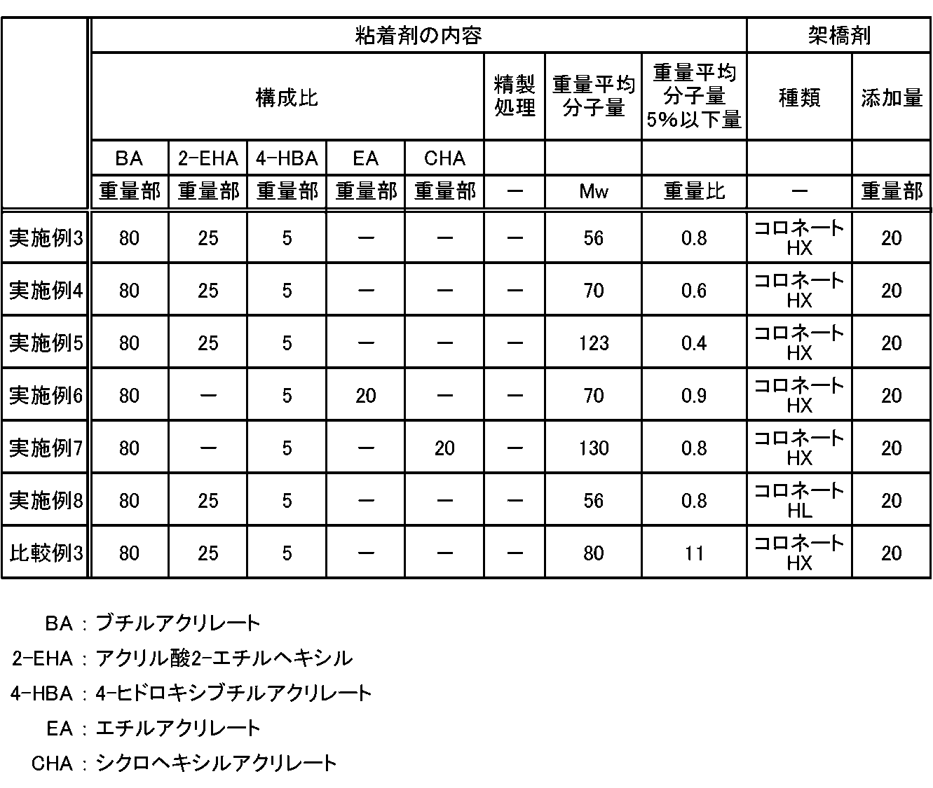
- Table 4 shows the contents of the pressure-sensitive adhesive used in the transparent laminates of Examples 3 to 8 and the type of the crosslinking agent.
- a crosslinking agent is included in an adhesive.
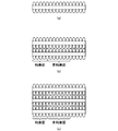
- FIG. 13 (a) to 13 (c) show a transparent laminated body that is a laminated body through a pressure-sensitive adhesive layer of a film-like member having a moth-eye shape on both sides, which is produced by the same method as in Example 1 of the present invention. It is a figure which shows another structure. That is, FIG. 13A shows the structure of a single layer, FIG. 13B shows the configuration of two laminated layers, and FIG. The adhesive used when laminating a plurality of sheets is provided over the entire surface of the film-like member. Thus, even with a transparent laminate having a moth-eye shape on both sides created by the same method as in Example 1, the effect can be obtained without problems.
- the transparent support, the base provided with a plurality of structures at a pitch equal to or less than the wavelength of visible light on at least one surface, and another base are laminated with an adhesive.
- a (meth) acrylic acid ester copolymer having a weight average molecular weight of 200,000 to 2,000,000 is used as an adhesive, and the weight average molecular weight is 50,000 or less and 5% or less. It became clear that this was preferable.
- By using such an adhesive it is possible to suppress changes in adhesive residue / peeling force over time on the nanostructure.
- a plurality of film-like members may be laminated and laminated, and one film-like member may have a gap between some of the areas of the film-like member, and the remaining area
- a plurality of laminates may be laminated using a pressure-sensitive adhesive capable of peeling between layers.
- the low molecular weight component having a weight average molecular weight of 50,000 or less of the pressure-sensitive adhesive may be 2 parts by weight or less.
- a plurality of film-like members may be laminated and bonded using an ultrasonic welding method or a heat welding method.
Landscapes
- Physics & Mathematics (AREA)
- General Physics & Mathematics (AREA)
- Optics & Photonics (AREA)
- Laminated Bodies (AREA)
- Helmets And Other Head Coverings (AREA)
Abstract
本発明は、モスアイ構造体(12)を備えたフィルム状部材(10)を積層することで、反射率の高まりや透過率の低下を防止し、剥離の即時性、簡便性を損なわず、接着剤の離形性も向上し、接着剤の厚みによる歪みの発生も回避し、視認性も確保することを目的とする。本発明の透明積層体(1)は、基体(11)の少なくとも一方の面に可視光波長以下のピッチからなる凹凸による構造体(12)が規則配列で設けられた複数のフィルム状部材(10)を備える。フィルム状部材(10)の少なくとも端部は粘着層(2)を介して積層されており、この積層されたフィルム状部材(10)間には対向する構造体(12)間に空隙(14)がある。
Description
本発明は、例えば可撓性を有する基体の少なくとも一方の面に可視光の波長以下のピッチで複数の構造体を設けたフィルム状部材を、当該フィルム状部材の面積の少なくとも一部の積層間を空隙とし複数枚積層貼合したことを特徴とする透明積層体、及びそれを用いた保護具に関する。
従来、2輪車や4輪車の自動車のオートレースの競技に用いられるヘルメットのシールドは、短時間で表面が汚れて視界が妨げられことが度々発生する。また、塗装作業の際に用いられる塗装用保護眼鏡は、塗装作業中に飛散した塗料等で眼鏡の表面が汚れて視界が妨げられることがある。また、医療用ゴーグルやフェイスシールドでは、手術中に患者から飛散した血液等でその表面が汚れることもある。
このように汚染物の飛来が予測できない環境では、即座に視界の回復を図ることが求められる。しかしながら、例えばオートレース中等、汚染物を拭き取る時間的余裕がない場合や、外科的手術中等、そもそも汚染物が危険物であることから接触することが好ましくない場合もある。このような問題は、前述した自動車競技や塗装作業等以外でも、ヘルメット、ゴーグル、保護眼鏡等を使用する環境では頻繁に発生している。
このような問題を解決するために、従来、ヘルメットのシールドや塗装用保護眼鏡の表面に簡単に剥離可能な保護フィルムを複数枚積層しておき、汚れによって視界が妨げられた際には、一番上層の保護フィルムを汚れと共に剥離し視界を回復させることが行われている。この種の技術について、例えば特許文献1では、ヘルメットのシールド部分を覆うように複数のシート状保護カバー、即ち使い捨てのバイザーを貼り付けたヘルメットのシールド部分の保護装置が開示されている。
しかしながら、上記のように保護装置を単なる保護フィルムの積層構造とすると、積層した各層間における界面で反射が生じるなどする。また、単純に積層枚数の増加に伴い透過性が低下する(積層枚数に限界ができる)等の問題がある。
例えば、前述した保護フィルムとしては、一般に透明なプラスチックフィルムを用いることができる。このプラスチックフィルムとしては、屈折率が1.4~1.6のものが汎用されており、フィルムの表裏でそれぞれ4~5%程度の光の反射があり、全体の透過率としては90~92%程度になっている。1枚のフィルムでは90%程度の透過率であるが、2枚重ねた場合は81%、3枚重ねた場合は73%と、複数枚重ねるごとに光線の透過率が下がり見えづらくなる問題がある。
一方、可視光波長以下のピッチを備えたモスアイ構造体の光学素子、フィルムは、広く知られている。例えば、特許文献2に開示されているように、透明基材上にモスアイ構造体を備える方法として、未硬化の紫外線硬化樹脂を、表面に構造体形状を備えた原盤の間に挟持し光照射させて得る手法がある。
このようなモスアイ構造体は、液晶ディスプレイ等に用いられる特定波長に対応したARフィルムとは異なり、基本的には全波長対応なので、当該モスアイ構造体を介して被写体を見たとき、その色味が変わらない等といった利点もある。
このようなモスアイ構造体の利点に着目し、例えば、特許文献3では、表面の微細構造が発現するモスアイ効果によって低反射率が実現された低反射透明板及びそれを用いた展示用ケースが開示されている。
しかしながら、例えば前述した特許文献2に開示されたように、紫外線硬化樹脂でモスアイ構造体を得る場合、樹脂の性質上、摩擦によって構造体が破壊されるなどして光学性能が低下する場合がある。そのため、ヘルメットのシールドやゴーグル、保護眼鏡等への適用を想定すると、その表面に視認を妨害する汚れが付着した場合、これを拭き取ることは望ましくない。
そこで、このような摩擦による破壊の問題や、前述したような即時的な視界の確保の観点から、基体の一方の面にモスアイ構造体を備えた保護フィルムを複数枚積層して透明積層体とし、汚れによって視界が妨げられた際には、一番上層の保護フィルムを汚れと共に剥離し視界を回復させることが考えられる。しかしながら、この場合、保護フィルムのモスアイ構造体の全面にわたって貼り合わせると、剥離の即時性、簡便性の観点から望ましくない。さらに、接着剤の厚みによる歪みも生じる可能性がある。
そこで、本発明は上述したような技術的な課題に鑑みてなされたもので、モスアイ構造体を備えたフィルム状部材を積層することで、反射率の高まりや透過率の低下を防止しつつ、剥離の即時性、簡便性を損なわず、例えば狭い幅とするなど接着領域を限定することで接着剤の離形性も向上し、接着剤の厚みによる歪みの発生も回避し、視認性も確保できる透明積層体、及びそれを用いた保護具を提供することを目的とする。
上述したような技術的な課題を解決するために、本発明の第1の態様に係る透明積層体は、基体の少なくとも一方の面に可視光波長以下のピッチからなる凹凸による構造体が設けられた複数のフィルム状部材を備え、前記フィルム状部材の少なくとも端部は粘着層を介して積層されており、この積層されたフィルム状部材間には対向する上記構造体間に空隙がある。
さらに、本発明の第2の態様による保護具は、このような透明積層体が視認部位に設けられている。
したがって、本発明に係る透明積層体、及びそれを用いた保護具によれば、モスアイ構造体を備えたフィルム状部材を積層することで、反射率の高まりや透過率の低下を防止しつつ、剥離の即時性、簡便性を損なわず、接着剤の離形性も向上し、接着剤の厚みによる歪みの発生も回避し、視認性も確保することができる。
以下、本発明の透明積層体、及びそれを用いた保護具に係る好適な実施形態について図面を参照しながら説明する。なお、本発明の透明積層体、及びそれを用いた保護具は、以下の記述に限定されるものではなく、本発明の要旨を逸脱しない範囲において、適宜変更可能である。
先ず、本発明の透明積層体について概略説明すると、可撓性を有する基体の表裏面に可視光波長以下のピッチで構造体を設けている。以下、反射防止機能を有する微細な凹凸構造体を「モスアイ構造体」と称する。そして、複数のフィルム状部材を積層する際に、フィルム状部材間に空隙ができるようにする。構造体の間に所定の空隙ができるようにするため、フィルム状部材の粘着層の粘着領域を適宜設定できる。例えば、端部にのみ接着層を設ける態様があり、この接着層は線で形成しても点で形成されていてもよい。また、どちらも備えた形でもよい。また、接着層はフィルム部材の端部のみでなく、全面にわたって設けられた態様を除外するものではなく、この場合は端部と端部位外の領域で剥離性が異なればよい。望ましくは、端部以外の剥離性が、端部よりも弱いことが求められる。
その他の態様として、フィルム状部材の端部もしくはその一部を物理的に固定して積層することもできる。一例として、フィルム状部材を積層した状態において、ピンで固定する、ないしは固定化されたピンやフックにひっかける、などして固定化する。この場合、端部もしくはその一部に設けられた固定部は、積層体が安定するように設けられていることが求められる。フィルム状部材の一部は切り込みなどの加工がなされていてもよい。更に、超音波溶着法又は熱溶着法を用いて積層を固定化させてもよい。
即ち、従来のフィルムでは、積層により光学性能の低下が生じていたことに鑑みて、本発明では、モスアイ構造体を備えたフィルム状部材を積層する。そして、モスアイ構造体が片面にのみ設けられているフィルム状部材の積層構造では、透過率の低下やフィルム状部材の裏面側での反射などの問題が発生するため、両面にモスアイ構造が設けられたフィルム状部材を用いて透明積層体を構成する。これにより透過性低下のない積層シールド構成とすることができ、透過性が向上するので積層枚数を増やすこともできる。但し、片面にモスアイ構造体を備えたものを除外するものではない。
積層は接着剤等の粘着層によってなされると固定化が容易になる。この接着剤は装着時に視野外となるような外周部に設けられることが望ましい。フィルム状部材の全面に接着剤を設けないようにすることで、(1)フィルム状部材自体の剥離性向上、(2)接着剤の離形性(残渣による視認性低減回避)向上、(3)接着剤の厚みによる歪みの発生の回避、などといった特性とコストを両立した条件を見出し易くなる。但し、全面を粘着層により貼り合わせるものを除外するものではない。
モスアイ構造体を備えたフィルム状部材を積層することで、シールドの視認性が汚れなどで低下しても、必要に応じてフィルム状部材を剥離することで低下要因ごと取り除くことができるので、シールドを備えた保護具の利便性をも高めることもできる。
以上の概要を踏まえて、以下、本発明の実施形態について詳述する。
<実施形態>
図1は本発明の一実施形態に係る透明積層体の構成の一例を示す概略図である。
図1に示されるように、この透明積層体1は、複数の光学素子としてのフィルム状部材10が、接着剤等による粘着層2により接合され、構成されている。各フィルム状部材10は、基体11の両面に基底層13を介して構造体12が設けられている。
光学素子としてのフィルム状部材10は、対向する表面及び裏面の両面が反射防止機能を有している。
即ち、フィルム状部材10は、表面および裏面を有する基体11と、この基体11の表面及び裏面に積層された基底層13と、この基底層13を介して設けられた複数の構造体12とを備えている。複数の構造体12は、基体11の表面及び裏面において、基底層13の上に複数の列をなすように規則的に配置されている。こうして、フィルム状部材10の表面及び裏面は複数の構造体12からなるモスアイ構造体による凹凸形状を有する(但し、表面のみに構造体12を設けることもできる。)。
つまり、フィルム状部材10の表面及び裏面は、可視光の波長以下のピッチで複数の構造体が設けられたモスアイ構造体による凹凸面となっている。このような凹凸面をフィルム状部材10の表面及び裏面に設けることで、波長依存性が少なく、視認性の優れた光学調整機能を、透明積層体1が装着された被着体の表面に付与することができる。即ち、視認性に優れた被着体を実現することに寄与することができる。
ここで、「光学調整機能」とは、透過特性や反射特性の光学調整機能を示す。光学素子としてのフィルム状部材10は、例えば可視光に対して透明性を有しており、その屈折率nは、好ましくは1.30以上2.00以下、より好ましくは1.34以上2.00以下の範囲内であることが好ましい。但し、これには限定されない。
なお、構造体12の屈折率は、粘着層2および基体11の屈折率と同様又は略同様であることが好ましい。内部反射を抑制し、コントラストを向上できるからである。
図1では、構造体12が基底層13を介して基体11の表裏面に形成される例を示したが、この基底層13は、基体11に対する構造体12の密着性を向上させる役割を担っている。この場合、基底層13は、構造体12の底面側に当該構造体12と一体成形される光学層であって、透明性を有しており、構造体12と同様のエネルギー線硬化性樹脂組成物などを硬化することにより形成されてよい。
また、例えば図2に示されるように、基底層13を有せず、基体21の上に複数の構造体22によるモスアイ構造が直接形成されたフィルム状部材20としてもよい。
さらに、基体と構造体とは、例えば、図3に示されるように一体成形されてもよい。すなわち、この図3の構成の場合、基体31の両面に構造体32が一体成形され、フィルム状部材30が構成されることになる。
ここで、基体11について更に言及する。
基体11は、例えば、透明性を有する透明基体である。基体11の材料としては、例えば、透明性を有するプラスチック材料を主成分とするものが挙げられるが、これらの材料に特に限定されるものではない。
基体11としてプラスチック材料を用いる場合、プラスチック材料の表面の表面エネルギー、塗布性、すべり性、平面性などをより改善するために、表面処理により不図示の下塗り層を更に設けるようにしてもよい。この下塗り層としては、例えば、オルガノアルコキシメタル化合物、ポリエステル、アクリル変性ポリエステル、ポリウレタンなどが挙げられる。また、下塗り層を設けるのと同等の効果を得るために、基体11の表面に対してコロナ放電処理、UV照射処理などを行うようにしてもよい。
基体11がプラスチックフィルムである場合、当該基体11は、例えば、上述の樹脂を伸延、あるいは溶剤に希釈後フィルム状に成膜して乾燥するなどの方法で得ることができる。基体11の厚さは、光学積層体1の用途に応じて適宜選択することが好ましく、例えば10μm以上500μm以下程度であってよい。基体11の形状としては、例えば、フィルム状、プレート状等を挙げることができるが、特にこれら形状に限定されるものではない。なお、フィルムにはシートが含まれるものとする。
そして、基体11の材料としては、例えば、メチルメタクリレート(共)重合体、ポリカーボネート、スチレン(共)重合体、メチルメタクリレート-スチレン共重合体、セルロースジアセテート、セルローストリアセテート、セルロースアセテートブチレート、ポリエステル、ポリアミド、ポリイミド、ポリエーテルスルフォン、ポリスルフォン、ポリプロピレン、ポリメチルペンテン、ポリ塩化ビニル、ポリビニルアセタール、ポリエーテルケトン、ポリウレタン、ガラス等が挙げられるが、これらには限定されない。
次に、構造体12について更に言及する。
一般に、可視光の波長帯域は360nm~830nmであるが、この実施形態では、構造体12を可視光の波長帯域以下のサイズで規則配列している。かかる観点から、構造体12の配置ピッチは350nmを超えないものとする。構造体12は、錐体状、柱状、針状など、種々の形状でよい。構造体12は、例えばエネルギー線硬化性樹脂組成物などを硬化することで形成される。構造体12を形成するエネルギー線硬化性樹脂生成物は、基体11の両面で異なる物性を持っても良い。例えば、使用の用途によって、撥水性、親水性を使い分けることにより、防曇などの機能を特定の面に持たせることができる。
エネルギー線硬化性樹脂組成物としては、紫外線硬化性樹脂組成物を用いることが好ましい。また、エネルギー線硬化性樹脂組成物が、必要に応じてフィラーや機能性添加剤などを含んでいてもよい。
紫外線硬化性樹脂組成物は、例えばアクリレート及び開始剤を含んでいる。
そして、紫外線硬化性樹脂組成物は、例えば単官能モノマー、二官能モノマー、多官能モノマー等を含み、具体的には、以下に示す材料を単独又は複数混合したものである。
即ち「単官能モノマー」としては、例えば、カルボン酸類(アクリル酸)、ヒドロキシ類(2-ヒドロキシエチルアクリレート、2-ヒドロキシプロピルアクリレート、4-ヒドロキシブチルアクリレート)、アルキル、脂環類(イソブチルアクリレート、t-ブチルアクリレート、イソオクチルアクリレート、ラウリルアクリレート、ステアリルアクリレート、イソボニルアクリレート、シクロヘキシルアクリレート)、その他機能性モノマー(2-メトキシエチルアクリレート、メトキシエチレンクリコールアクリレート、2-エトキシエチルアクリレート、テトラヒドロフルフリルアクリレート、ベンジルアクリレート、エチルカルビトールアクリレート、フェノキシエチルアクリレート、N,N-ジメチルアミノエチルアクリレート、N,N-ジメチルアミノプロピルアクリルアミド、N,N-ジメチルアクリルアミド、アクリロイルモルホリン、N-イソプロピルアクリルアミド、N,N-ジエチルアクリルアミド、N-ビニルピロリドン、2-(パーフルオロオクチル)エチル アクリレート、3-パーフルオロヘキシル-2-ヒドロキシプロピルアクリレート、3-パーフルオロオクチルー2-ヒドロキシプロピルアクリレート、2-(パーフルオロデシル)エチル アクリレート、2-(パーフルオロー3-メチルブチル)エチル アクリレート)、2,4,6-トリブロモフェノールアクリレート、2,4,6-トリブロモフェノールメタクリレート、2-(2,4,6-トリブロモフェノキシ)エチルアクリレート)、2-エチルヘキシルアクリレートなどを挙げることができる。
「二官能モノマー」としては、例えば、トリ(プロピレングリコール)ジアクリレート、トリメチロールプロパン ジアリルエーテル、ウレタンアクリレートなどを挙げることができる。
「多官能モノマー」としては、例えば、トリメチロールプロパントリアクリレート、ジペンタエリスリトールペンタ及びヘキサアクリレート、ジトリメチロールプロパンテトラアクリレートなどを挙げることができる。
「開始剤」としては、例えば、2,2-ジメトキシ-1,2-ジフェニルエタン-1-オン、1-ヒドロキシ-シクロヘキシルフェニルケトン、2-ヒドロキシ-2-メチル-1-フェニルプロパン-1-オンなどを挙げることができる。
「フィラー」としては、例えば、無機微粒子および有機微粒子のいずれも用いることができる。無機微粒子としては、例えば、SiO2、TiO2、ZrO2、SnO2、Al2O3などの金属酸化物微粒子を挙げることができる。
「機能性添加剤」としては、例えば、レベリング剤、表面調整剤、消泡剤などを挙げることができる。
ここで、この実施形態に係る透明積層体は、可視光波長以下のピッチからなる凹凸による構造体12からなるモスアイ構造体が基体11の表裏面に設けられた複数のフィルム状部材10を備え、当該フィルム状部材10の少なくとも端部は接着剤などの粘着層2によって積層されているが、積層されたフィルム状部材10間には上記構造体12間に空隙14がある。空隙14のパターンとしては、種々のパターンが考えられるが、いくつかの例を図4(a)乃至(c)に示している。空隙14は、接着剤など樹脂で設けられる場合も含む。つまり空隙14は、空気層でもよく、樹脂層でもよい。
即ち、図4(a)は粘着層2の厚みにより対向する構造体12同士が接触せずに空気層ができている場合を示している。図4(b)は対向する構造体12の先端同士が点接触しているが、構造体12は凹凸の連続であることから凹部において空気層ができている場合を示している。そして、図4(c)は構造体12の先端が対向する構造体12の凹部に入り込んでいるが、完全には入り込まないので所定の空気層ができる場合を示している。これらの場合、各空気層が空隙となって存在する。尚、空隙は空気層には限定されず、例えば構造体12の全面を粘着層2により貼り付けた場合には、当該粘着層2も広義には空隙に含まれてよいことは勿論である。
この実施形態では、構造体12は、規則配列となっているので、縦方向、横方向いずれで見た場合でも規則性を有しているので、積層性も良好である。
積層は接着剤等の粘着層2によってなされるが、この実施形態では、粘着層2は装着時に視野外となるような外周部に設けられる。つまり、視認部以外に設ける。例えば、フィルム状部材10の四隅に、あるいは左右の端部において短手方向に所定幅、所定長で延びる領域で、フィルム状部材2の構造体12同士を粘着層2により部分的に接合するようにしてもよい。
このように、フィルム状部材10の全面には粘着層2としての接着剤を設けないようにすることで、フィルム状部材10自体の剥離性が向上し、粘着層2としての接着剤の離形性(残渣による視認性低減回避)も向上し、粘着層2としての接着剤の厚みによる歪みの発生も回避することができるようになる。なお、透過性能を最優先とする場合には、接着剤等による全面貼り付けとしてもよいことは勿論である。この場合、視認性向上のため屈折率等も好適となるように樹脂組成が適宜選択される。
また、この実施形態に係る透明積層体1は、反射防止機能を実現するモスアイ構造体を両面に有する積層体であり、複数の光学素子としてのフィルム状部材が、複数の粘着層により接合されているが、図5に示されるように、該透明積層体1は貼合層3を介して被着体4に貼り合わされる。この被着体としては、オートレース等で用いられるヘルメットのバイザーや、医療用のフェイスシールド、医療用のディスプレイ、塗装用保護眼鏡等が挙げられる。但し、これらには限定されず、汚染物の飛来が予想できず、汚染された場合に即時的に視界の回復が必要な環境、乃至はそもそも汚染物が危険物であり接触が好ましくない環境、などで用いられる各種の光学用品が含まれる。また、この実施形態に係る透明積層体をARフィルムの上に貼り付けしてもよい。なお、図5の透明積層体1が装着された被着体は、本実施形態の保護具の一例に相当する。
なお、貼合層3は、例えば、ゴムやシリコン等の粘着剤を用いることができるが、透明性を実現するためにはアクリル系粘着剤が好適である。また、粘着剤としては、重量平均分子量20万~200万好ましくは、50万~200万の(メタ)アクリル酸エステル系共重合体を用い、その重量平均分子量5万以下が5%以下であることとしてもよい。この場合は粘着剤がフィルム全面であっても、剥離性がよいので、実用上問題はない。
以上説明したように、本発明の実施形態に係る透明積層体は、可撓性を有する透明基材としての基体11の両面に可視光の波長以下のピッチで複数の構造体12を設けたフィルム状部材10を、当該フィルム状部材10の面積の一部の積層間を空隙とし、複数枚積層貼合することにより構成される。
したがって、例えばオートレース中等、汚染物を拭き取る時間的余裕がない場合や、外科的手術中等、そもそも汚染物が危険物であることから接触することが好ましくない場合でも、汚染されたフィルム状部材10を1枚ずつ剥離すればよいので、即時に視界の回復を図ることができ、更に危険物に接触しなくても済む。
しかも、フィルム状部材10の両面に複数の構造体12の規則配列によるモスアイ構造体を設けることで、フィルム状部材10が複数枚積層され、接着剤等の粘着層2で接合されたときに、モスアイ構造体間に空隙ができても、透過性の低下を防止し、界面での反射を低減し反射防止性能を実現することができる。
また、このようなモスアイ構造体は、液晶ディスプレイ等に用いられる特定波長に対応したARフィルムとは異なり、基本的には全波長対応なので、当該モスアイ構造体を介して被写体を見たとき、その色味が変わらない等といった利点もある。また、モスアイ構造体の特性から、照度が急激に跳ね上がるような環境、人間の目が照度差に慣れるまでに時間がかかるような環境での使用にも好適であるといえる。
さらに、前述したように、フィルム状部材10の構造体12の一部のみを接着剤等の粘着層2により接合するようにしているので、剥離の即時性、簡便性も図られ、更に接着剤の厚みによる歪みも生じない。シールド面が汚れ、フィルム状部材10を剥離する際には一部の面積のみ接着されていることから、軽い力で剥離することができる。また、視野の大部分を粘着層2を有しない領域とすることで、高温での保存や使用時でも視界内に粘着層2の糊残りが発生せず、良好な視界が得られる。広範な面積に接着層を設ける場合、端部と視認部で剥離力に差を設けるのは、上記した軽い力による剥離性を阻害させないためである。
また、複数のフィルム状部材10を全面貼り付けした場合には、2つの透明な物質の間に光の波長に比較しうる程度の細い隙間があれば同心円状のニュートンリングが観察されることがあるが、この実施形態に係る透明積層体1では、各フィルム状部材10を両面モスアイ構造とすることで、その発生を抑制することができる。
本実施形態によれば、モスアイ構造体を備えたフィルム状部材を積層することで、反射率の高まりや透過率の低下を防止しつつ、剥離の即時性、簡便性を損なわず、接着剤の離形性も向上し、接着剤の厚みによる歪みの発生も回避し、視認性も確保できる透明積層体、及びそれを用いた保護具を提供することができる。
尚、以上の実施形態において、例えば、フィルム状部材の裏面側に設けられる構造体を親水性とし、表面側に設けられる構造体を撥水性とし、透明積層体を構成するフィルム状部材を1枚ずつ剥離したときに、剥離したフィルム状部材側に接着剤等の粘着層が残るように構成することで、剥離後に接着剤等が表面に残り、飛来する汚染物の付着を助長させるような事態が発生するのを防止することもできる。
また、フィルム状部材の左右端部に取り外し用のつまみ(突出部)を1枚ずつ交互に設けて、左からフィルム状部材を外した後は、右から、そして左からと交互にフィルム状部材を剥離するように構成してもよい。また、フィルム状部材10の残りの枚数を把握することができるように、当該つまみ部に枚数を数字で表示してもよい。
そして、この実施形態に係る透明積層体が適用される被着体としては、オートレース等で用いられるヘルメットのバイザーや、医療用のフェイスシールド、医療用のディスプレイ、塗装用の保護眼鏡等を挙げたが、人の目に対する効果が期待できるもののほか、カメラや望遠鏡等の光学機器への適用も可能である。光学機器への適用の場合、屈折率などの光学的な感度は人間のそれとは直接的には異なるため、樹脂を充填させるなどして対応する場合が出てくる。
以下、本発明の実施例について説明する。
(実施例1)
先ず、光の波長以下の微細な凹凸形状であるモスアイ形状をもつ原盤上にUV硬化樹脂を数滴垂らし、基体に相当する透明基材としてのポリカーボネイトフィルムをかぶせ、原盤全体にローラーにて拡げた。その後、透明基材としてのポリカーボネイトフィルム側から紫外線を照射し、樹脂の硬化を行った後、原盤から離型し、光学素子としてのフィルム状部材を得た。同様の手順でポリカーボネイトフィルムの反対面側にもモスアイ形状を原盤より転写し、両面に凹凸形状を備える光学素子としてのフィルム状部材を得た。こうして得られたフィルム状部材を粘着層としての接着剤等を用いて2層、3層、それぞれ積層し、単層のものを含め3種の透明積層体を得た。即ち、図6(a)は単層、図6(b)は2枚積層、図6(c)は3枚積層した透明積層体の構成をそれぞれ示している。この例では、粘着層はフィルム状部材の端部にのみ設けられているので、空隙は粘着面と非粘着面に分けられることになる。
先ず、光の波長以下の微細な凹凸形状であるモスアイ形状をもつ原盤上にUV硬化樹脂を数滴垂らし、基体に相当する透明基材としてのポリカーボネイトフィルムをかぶせ、原盤全体にローラーにて拡げた。その後、透明基材としてのポリカーボネイトフィルム側から紫外線を照射し、樹脂の硬化を行った後、原盤から離型し、光学素子としてのフィルム状部材を得た。同様の手順でポリカーボネイトフィルムの反対面側にもモスアイ形状を原盤より転写し、両面に凹凸形状を備える光学素子としてのフィルム状部材を得た。こうして得られたフィルム状部材を粘着層としての接着剤等を用いて2層、3層、それぞれ積層し、単層のものを含め3種の透明積層体を得た。即ち、図6(a)は単層、図6(b)は2枚積層、図6(c)は3枚積層した透明積層体の構成をそれぞれ示している。この例では、粘着層はフィルム状部材の端部にのみ設けられているので、空隙は粘着面と非粘着面に分けられることになる。
(実施例2)
先ず、光の波長以下の微細な凹凸形状であるモスアイ形状をもつ原盤上にUV硬化樹脂を数滴垂らし、基体に相当する透明基材としてのポリカーボネイトフィルムをかぶせ、原盤全体にローラーにて拡げた。その後、透明基材としてのポリカーボネイトフィルム側から紫外線を照射し、樹脂の硬化を行った後、原盤から離型し、光学素子としてのフィルム状部材を得た。この得られたフィルム状部材を粘着層としての接着剤等を用いて2層、3層、それぞれ積層し、単層のものを含め3種の透明積層体を得た。即ち、図7(a)は単層、図7(b)は2枚積層、図7(c)は3枚積層した透明積層体の構成をそれぞれ示している。この例では、粘着層はフィルム状部材の端部にのみ設けられているので、空隙は粘着面と非粘着面に分けられることになる。
先ず、光の波長以下の微細な凹凸形状であるモスアイ形状をもつ原盤上にUV硬化樹脂を数滴垂らし、基体に相当する透明基材としてのポリカーボネイトフィルムをかぶせ、原盤全体にローラーにて拡げた。その後、透明基材としてのポリカーボネイトフィルム側から紫外線を照射し、樹脂の硬化を行った後、原盤から離型し、光学素子としてのフィルム状部材を得た。この得られたフィルム状部材を粘着層としての接着剤等を用いて2層、3層、それぞれ積層し、単層のものを含め3種の透明積層体を得た。即ち、図7(a)は単層、図7(b)は2枚積層、図7(c)は3枚積層した透明積層体の構成をそれぞれ示している。この例では、粘着層はフィルム状部材の端部にのみ設けられているので、空隙は粘着面と非粘着面に分けられることになる。
(比較例1)
比較例1としては、市販されている光学用PETフィルムを粘着層として接着剤等を用いて2層、3層、それぞれ積層し、単層のものを含め3種の透明積層体を得た。即ち、図8(a)は単層、図8(b)は2枚積層、図8(c)は3枚積層した透明積層体の構成をそれぞれ示している。この例では、粘着層は光学用PETフィルムの端部にのみ設けられているので、空隙は粘着面と非粘着面に分けられることになる。
比較例1としては、市販されている光学用PETフィルムを粘着層として接着剤等を用いて2層、3層、それぞれ積層し、単層のものを含め3種の透明積層体を得た。即ち、図8(a)は単層、図8(b)は2枚積層、図8(c)は3枚積層した透明積層体の構成をそれぞれ示している。この例では、粘着層は光学用PETフィルムの端部にのみ設けられているので、空隙は粘着面と非粘着面に分けられることになる。
(光学特性評価)
実施例1~2の透明積層体と比較例1の透明積層体との反射スペクトル及び透過スペクトルを、紫外可視分光光度計(日本分光株式会社、製品名:V-500)を用いて測定した。
実施例1~2の透明積層体と比較例1の透明積層体との反射スペクトル及び透過スペクトルを、紫外可視分光光度計(日本分光株式会社、製品名:V-500)を用いて測定した。
(結果)
以上の光学特性の評価結果は、以下の表1,2に示される。
以上の光学特性の評価結果は、以下の表1,2に示される。
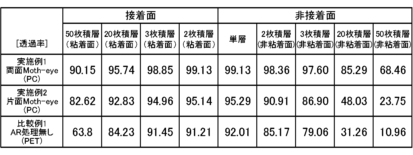
即ち、各実施例1~2と比較例1の積層構造毎の透過率の評価結果は以下の表1に示される通りである。
そして、この結果を図示した様子は、図9,10に示される。
また、各実施例1~2と比較例1の積層構造毎の反射率の評価結果は以下の表2に示される通りである。
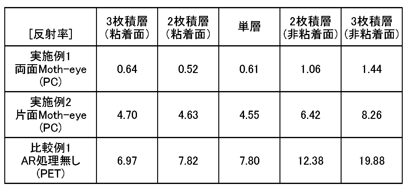
そして、この結果を図示した様子は、図11に示される。
(考察)
上記評価結果から、n層の構造の透過率は、単層の場合の透過率のおよそn乗倍ととらえることができる。先ず、実施例1では、表1、図9より、3枚積層した場合でも透過率が非常に高く、実施例2,3、比較例1の単層の透過率以上の透過率を確保できていることが明らかになった。即ち、例えば、実施例2の単層の透過率は95.29%であるのに対して、実施例1では、接着面では2枚積層が99.13%、3枚積層が98.85%、そして20枚積層でも95.74%となり、非接着面でも2枚積層が98.36%、3枚積層が97.60%となり、実施例2,3、比較例1の単層の数値を上回っており、透過率が良好な状態が維持されていることが明らかになった。
上記評価結果から、n層の構造の透過率は、単層の場合の透過率のおよそn乗倍ととらえることができる。先ず、実施例1では、表1、図9より、3枚積層した場合でも透過率が非常に高く、実施例2,3、比較例1の単層の透過率以上の透過率を確保できていることが明らかになった。即ち、例えば、実施例2の単層の透過率は95.29%であるのに対して、実施例1では、接着面では2枚積層が99.13%、3枚積層が98.85%、そして20枚積層でも95.74%となり、非接着面でも2枚積層が98.36%、3枚積層が97.60%となり、実施例2,3、比較例1の単層の数値を上回っており、透過率が良好な状態が維持されていることが明らかになった。
また、一般にJIS規格(JIS T8147 保護めがね)の要求視感透過率は85%以上であるが、図10からも明らかなように、実施例1では、20枚積層した場合でも、この要求視感透過率を満たしていることが分かる。これは、規格製品への適用の幅が広いことを意味する。反射率についても表2、図11に示したように、2枚積層、3枚積層の場合であっても、粘着面、非粘着面ともに、4%を下回る良好な結果となっている。
実施例2では、表1、図9,10に示したように、接着面においては、2枚積層、3枚積層、20枚積層の場合であっても、比較例1の単層の透過率以上の透過率を確保できている。しかしながら、実施例2では、非粘着面での透過率が1層増える毎に約4%程度落ちており、微細構造の無い面での反射による影響が多少見られる。また、反射率については、粘着面では2枚積層、3枚積層の場合であっても、比較例1の単層の反射率に比して良好な結果を得ており、非粘着面においても、2枚積層の場合は、比較例1の単層の反射率に比して良好な結果となっていることが分かる。
一方、比較例1ではフィルムの両界面での反射の影響がでており、3枚重ねた状態での透過率は非粘着面で79%である。これは、JIS規格(JIS T8147 保護めがね)の要求視感透過率85%を満たしておらず、実際のシールドに適用した場合の視界への悪影響は顕著であるといえる。
なお、ここでは、用途の一例としてJIS規格製品への適用の可能性を述べたが、用途により要求される透過率や反射率は異なってくる。その場合、透過率であれば、単層の場合の透過率の積層n乗倍で、おおよその限界積層数を算定することが可能である。
次に、実施例3~8について詳述する。
(実施例3)
以下、ナノ構造体シートの作製、粘着剤樹脂の作製、そして透明積層体の作製の各手順について説明する。
以下、ナノ構造体シートの作製、粘着剤樹脂の作製、そして透明積層体の作製の各手順について説明する。
(1)ナノ構造体シートの作製
先ず、ポリカーボネート(PC)支持体(屈折率=1.58、厚み100um)の表面に、UV硬化性の樹脂(硬化後の屈折率=1.53)をバーコーターにて4um塗布し、ドットピッチ230nm、隣接するドット間隔153nmとして凹凸220nmとしたナノ構造体の型を合わせ、PC基材側よりUV光を照射し、硬化させ、表面にナノ構造体を有するシートを得た。
先ず、ポリカーボネート(PC)支持体(屈折率=1.58、厚み100um)の表面に、UV硬化性の樹脂(硬化後の屈折率=1.53)をバーコーターにて4um塗布し、ドットピッチ230nm、隣接するドット間隔153nmとして凹凸220nmとしたナノ構造体の型を合わせ、PC基材側よりUV光を照射し、硬化させ、表面にナノ構造体を有するシートを得た。
(2)粘着剤樹脂の作製
次に、主成分としてリビングラジカル重合により得た粘着剤、トルエン溶媒を添加して固形分25%とし、更に、架橋剤として日本ポリウレタン社製のコロネートHXを20重量部添加し、軽剥離処理のされたPETフィルム上へ塗布、乾燥し、更に軽剥離処理のされたポリプロピレン(OPP)フィルムにて挟み込み、常温にて1週間保管して粘着剤を得た。
トルエン溶媒を添加して固形分25%とした。
(主成分は以下になる)
・ブチルアクリレート :80重量部
・アクリル酸2-エチルヘキシル :25重量部
・4-ヒドロキシブチルアクリレート :5重量部
次に、主成分としてリビングラジカル重合により得た粘着剤、トルエン溶媒を添加して固形分25%とし、更に、架橋剤として日本ポリウレタン社製のコロネートHXを20重量部添加し、軽剥離処理のされたPETフィルム上へ塗布、乾燥し、更に軽剥離処理のされたポリプロピレン(OPP)フィルムにて挟み込み、常温にて1週間保管して粘着剤を得た。
トルエン溶媒を添加して固形分25%とした。
(主成分は以下になる)
・ブチルアクリレート :80重量部
・アクリル酸2-エチルヘキシル :25重量部
・4-ヒドロキシブチルアクリレート :5重量部
(3)透明積層体の作製
工程(1)で得られたナノ構造体が設けられていない一方の面にコロナ処理を施し、工程(2)で作成した粘着剤樹脂の軽剥離OPPを剥離し貼合した。これを、別の工程(1)で得られたナノ構造体の表面にローラーで貼合することによって透明積層体を得た。図12(a)は単層、図12(b)は2枚積層、図12(c)は3枚積層した透明積層体の構成をそれぞれ示している。この例では、複数枚積層する際に用いる粘着剤は、フィルム状部材の全面に亘り設けられている。
工程(1)で得られたナノ構造体が設けられていない一方の面にコロナ処理を施し、工程(2)で作成した粘着剤樹脂の軽剥離OPPを剥離し貼合した。これを、別の工程(1)で得られたナノ構造体の表面にローラーで貼合することによって透明積層体を得た。図12(a)は単層、図12(b)は2枚積層、図12(c)は3枚積層した透明積層体の構成をそれぞれ示している。この例では、複数枚積層する際に用いる粘着剤は、フィルム状部材の全面に亘り設けられている。
(実験例4~8)
実施例4乃至8は、詳細は後述するように樹脂の組成がそれぞれ異なる以外、前述した実施例3と同様にして作製した。
実施例4乃至8は、詳細は後述するように樹脂の組成がそれぞれ異なる以外、前述した実施例3と同様にして作製した。
(比較例3)
実施例3の組成にて、リビング重合ではなく、溶液重合した樹脂を使用した以外には、同様にして粘着剤を作製し、実施例3と同様に透明積層体を作製した。
実施例3の組成にて、リビング重合ではなく、溶液重合した樹脂を使用した以外には、同様にして粘着剤を作製し、実施例3と同様に透明積層体を作製した。
こうして得られた実施例3乃至8の透明積層体について、以下の評価を行った。
(光学特性)
全光線透過率(Tt)を、村上色彩製のヘイズメーターより計測した(JIS-K-7361)。
全光線透過率(Tt)を、村上色彩製のヘイズメーターより計測した(JIS-K-7361)。
(粘着剤特性)
重量平均分子量、平均重量分子量分布が5万以下の成分について、液体クロマトグラフィーにて計測して求めた。
重量平均分子量、平均重量分子量分布が5万以下の成分について、液体クロマトグラフィーにて計測して求めた。
(粘着剤の剥離強度)
ナノ構造体の支持体とナノ構造体間の剥離強度について、剥離角度90°、剥離スピード300mm/minにて剥離した際の荷重を、引っ張り試験機により求めた。
ナノ構造体の支持体とナノ構造体間の剥離強度について、剥離角度90°、剥離スピード300mm/minにて剥離した際の荷重を、引っ張り試験機により求めた。
(環境試験)
環境試験では、40℃/90%RH条件下にて10日間保管した後に、剥離強度、全光線透過率の変化を計測した。
環境試験では、40℃/90%RH条件下にて10日間保管した後に、剥離強度、全光線透過率の変化を計測した。
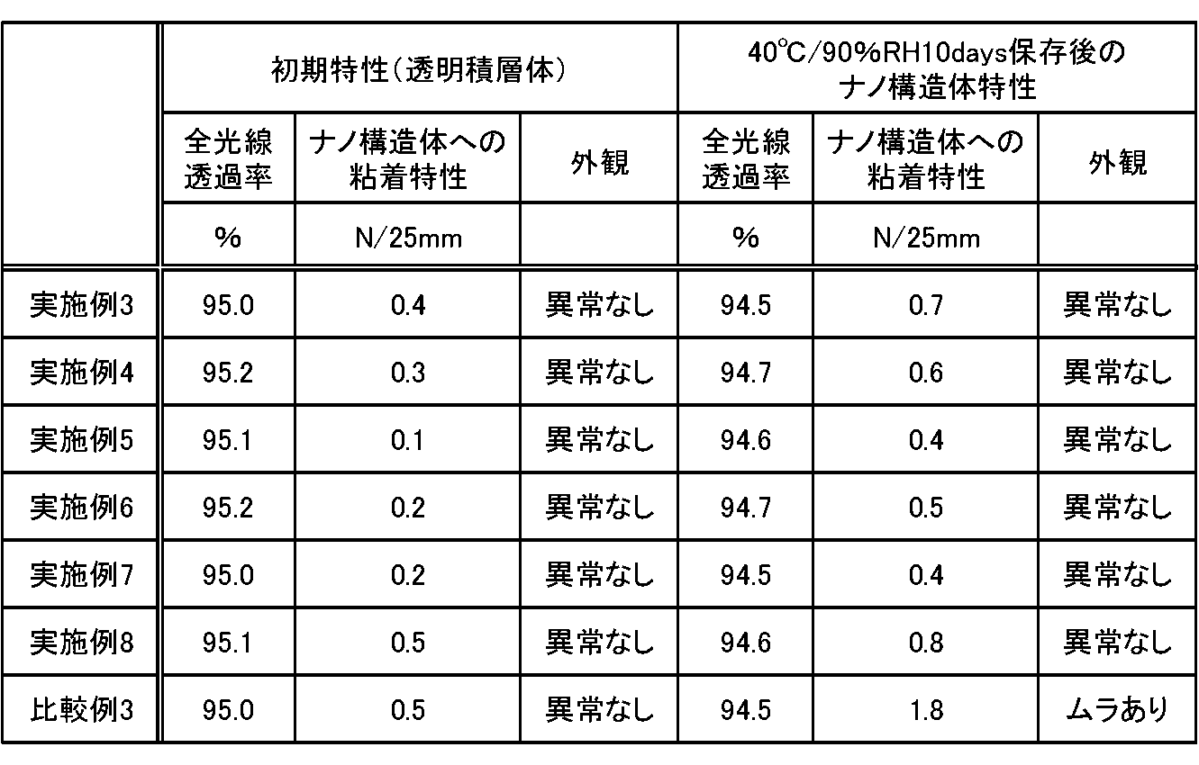
以上の評価結果は以下の表3に示される。
また、実施例3乃至8の透明積層体に用いた粘着剤の内容、並びに架橋剤の種類については、表4に示される。尚、粘着剤には、架橋剤を含む。
なお、図13(a)乃至(c)は、本発明の実施例1と同様の手法で作製した両面にモスアイ形状を備えたフィルム状部材の粘着層を介した積層体である透明積層体の他の構成を示す図である。即ち、図13(a)は単層、図13(b)は2枚積層、図13(c)は3枚積層した透明積層体の構成をそれぞれ示している。複数枚積層する際に用いる粘着剤は、フィルム状部材の全面に亘り設けられている。このように、実施例1と同様の手法で作成した両面にモスアイ形状を備えた透明積層体でも、問題なく効果が得られる。
(考察)
以上の実施例3乃至8に係る評価結果より、透明支持体と、少なくとも一方の面に可視光の波長以下のピッチで複数の構造体を設けた基体と他の基体とを粘着剤により積層して光透過性積層体を構成するに際し、粘着剤として、重量平均分子量20万~200万の(メタ)アクリル酸エステル系共重合体を用い、その重量平均分子量5万以下が5%以下であることが好ましいことが明らかとなった。このような粘着剤を用いることで、ナノ構造体への糊残り/剥離力の経時変化を抑制できる。
以上の実施例3乃至8に係る評価結果より、透明支持体と、少なくとも一方の面に可視光の波長以下のピッチで複数の構造体を設けた基体と他の基体とを粘着剤により積層して光透過性積層体を構成するに際し、粘着剤として、重量平均分子量20万~200万の(メタ)アクリル酸エステル系共重合体を用い、その重量平均分子量5万以下が5%以下であることが好ましいことが明らかとなった。このような粘着剤を用いることで、ナノ構造体への糊残り/剥離力の経時変化を抑制できる。
このような光透過性積層体では、フィルム状部材を複数枚積層貼合してよく、更に一のフィルム状部材を当該フィルム状部材の面積の一部の積層間を空隙とし、残りの面積の積層間を剥離可能な粘着剤を用いて複数枚積層貼合してもよい。また、前記粘着剤の重量平均分子量5万以下の低分子量成分が2重量部以下であることとしてもよい。また、フィルム状部材を、超音波溶着法や熱溶着法を用いて複数枚積層貼合してもよい。
従って、実施例3乃至8によれば、糊残り、粘着特性の劣化のない透明積層体が実現されることになる。
1 透明積層体
2 粘着層
3 貼合層
4 被着体
10 フィルム状部材
11 基体
12 構造体
13 基底層
14 空隙
20 フィルム状部材
21 基体
22 構造体
30 フィルム状部材
31 基体
32 構造体
2 粘着層
3 貼合層
4 被着体
10 フィルム状部材
11 基体
12 構造体
13 基底層
14 空隙
20 フィルム状部材
21 基体
22 構造体
30 フィルム状部材
31 基体
32 構造体
Claims (9)
- 基体の少なくとも一方の面に可視光波長以下のピッチからなる凹凸による構造体が設けられた複数のフィルム状部材を備え、
前記フィルム状部材の少なくとも端部において固定化されて積層されており、この積層されたフィルム状部材間には対向する上記構造体間に空隙がある
透明積層体。 - 上記構造体がフィルム状部材の両面に設けられている
請求項1記載の透明積層体。 - 上記空隙とは、上記構造体間に設けられた空気層である
請求項1又は2記載の透明積層体。 - 上記空隙とは、上記構造体間に設けられた樹脂層である
請求項1又は2記載の透明積層体。 - 上記固定化されたフィルム状部材は、上記端部としての外縁部に少なくとも設けられた粘着層によって剥離可能に接合される
請求項1乃至4のいずれかに記載の透明積層体。 - 上記粘着層は少なくとも視野部の全面に設けられ、剥離可能に接合される
請求項1乃至5のいずれかに記載の透明積層体。 - 上記粘着層は、重量平均分子量20万~200万のアクリル酸エステル系共重合体であり、その重量平均分子量5万以下が5%以下である
請求項6に記載の透明積層体。 - 上記フィルム状部材を、超音波溶着法又は熱溶着法を用いて複数枚積層貼合し、剥離可能に接合される
請求項1乃至7のいずれかに記載の透明積層体。 - 請求項1乃至8記載の透明積層体が視認部位に設けられている
保護具。
Priority Applications (2)
| Application Number | Priority Date | Filing Date | Title |
|---|---|---|---|
| US14/910,598 US10000037B2 (en) | 2013-08-09 | 2014-06-04 | Transparent laminate and protective tool including the same |
| EP14834273.6A EP3031602B1 (en) | 2013-08-09 | 2014-06-04 | Transparent laminate and protective tool including same |
Applications Claiming Priority (4)
| Application Number | Priority Date | Filing Date | Title |
|---|---|---|---|
| JP2013165708 | 2013-08-09 | ||
| JP2013-165708 | 2013-08-09 | ||
| JP2014069558A JP6493900B2 (ja) | 2013-08-09 | 2014-03-28 | 透明積層体、及びそれを用いた保護具 |
| JP2014-069558 | 2014-03-28 |
Publications (1)
| Publication Number | Publication Date |
|---|---|
| WO2015019529A1 true WO2015019529A1 (ja) | 2015-02-12 |
Family
ID=52460893
Family Applications (1)
| Application Number | Title | Priority Date | Filing Date |
|---|---|---|---|
| PCT/JP2014/002980 Ceased WO2015019529A1 (ja) | 2013-08-09 | 2014-06-04 | 透明積層体、及びそれを用いた保護具 |
Country Status (4)
| Country | Link |
|---|---|
| US (1) | US10000037B2 (ja) |
| EP (1) | EP3031602B1 (ja) |
| JP (1) | JP6493900B2 (ja) |
| WO (1) | WO2015019529A1 (ja) |
Cited By (3)
| Publication number | Priority date | Publication date | Assignee | Title |
|---|---|---|---|---|
| KR20210072042A (ko) * | 2018-11-08 | 2021-06-16 | 데쿠세리아루즈 가부시키가이샤 | 적층체, 적층체의 제조 방법, 광학체의 형성 방법 및 카메라 모듈 탑재 장치 |
| WO2022054933A1 (ja) * | 2020-09-11 | 2022-03-17 | 大日本印刷株式会社 | 透明積層フィルム、保護フィルム付き透明積層フィルムおよびフェイスシールド |
| JP7669705B2 (ja) | 2021-01-28 | 2025-04-30 | 大日本印刷株式会社 | 透明積層フィルム、保護フィルム付き透明積層フィルムおよびフェイスシールド |
Families Citing this family (9)
| Publication number | Priority date | Publication date | Assignee | Title |
|---|---|---|---|---|
| JP6684046B2 (ja) * | 2014-07-30 | 2020-04-22 | デクセリアルズ株式会社 | 透明積層体 |
| US11585962B2 (en) * | 2018-10-19 | 2023-02-21 | Racing Optics, Inc. | Transparent covering having anti-reflective coatings |
| US11635622B1 (en) * | 2018-12-07 | 2023-04-25 | Meta Platforms Technologies, Llc | Nanovided spacer materials and corresponding systems and methods |
| JP7816149B2 (ja) | 2020-06-30 | 2026-02-18 | 大日本印刷株式会社 | 透明積層体、画像表示装置、両面反射防止積層体、および顔用透明保護具 |
| US11708150B2 (en) | 2021-02-09 | 2023-07-25 | Safran Landing Systems Canada Inc. | Hybrid main landing gear fitting with detachable drag arm |
| US12140781B2 (en) | 2021-07-27 | 2024-11-12 | Laminated Film Llc | Low reflectance removable lens stack |
| US11307329B1 (en) | 2021-07-27 | 2022-04-19 | Racing Optics, Inc. | Low reflectance removable lens stack |
| JP7791771B2 (ja) | 2022-05-19 | 2025-12-24 | デクセリアルズ株式会社 | フィルム積層体、フィルム積層体の製造方法、保護具、保護具の製造方法 |
| JP2023170535A (ja) | 2022-05-19 | 2023-12-01 | デクセリアルズ株式会社 | フィルム積層体、フィルム積層体の製造方法、保護具、保護具の製造方法 |
Citations (18)
| Publication number | Priority date | Publication date | Assignee | Title |
|---|---|---|---|---|
| US5002326A (en) * | 1990-01-22 | 1991-03-26 | Westfield William R | Automotive windshield laminated protector |
| US5592698A (en) * | 1995-06-30 | 1997-01-14 | Woods; Marlen M. | Tear-off lens for transparent eye and face shield |
| JP2000192322A (ja) | 1998-12-24 | 2000-07-11 | Teac Corp | ヘルメットのシールド部分の保護装置 |
| JP2002528298A (ja) * | 1998-10-28 | 2002-09-03 | スリーエム イノベイティブ プロパティズ カンパニー | 剥離可能なシートを有する落書き防止および/または環境保護物品、それにより保護された基板、並びに使用方法 |
| JP2003222701A (ja) * | 2002-01-29 | 2003-08-08 | Seiko Epson Corp | 光学部品及びその製造方法 |
| WO2004000540A2 (en) * | 2002-06-24 | 2003-12-31 | Bart Wilson | Optical stack of laminated removable lenses |
| US6847492B2 (en) * | 1999-11-24 | 2005-01-25 | Bart Wilson | Optical stack of laminated removable lenses for face shields, windows, and displays |
| US20050015860A1 (en) * | 2003-06-19 | 2005-01-27 | Reaux Brian K. | Face and eye covering device |
| JP2010048902A (ja) | 2008-08-19 | 2010-03-04 | The Inctec Inc | 低反射透明板及びそれを用いた展示用ケース |
| WO2010073881A1 (ja) * | 2008-12-25 | 2010-07-01 | シャープ株式会社 | 貯液槽、液中観察器具及び光学フィルム |
| WO2011027909A1 (ja) * | 2009-09-02 | 2011-03-10 | ソニー株式会社 | 導電性光学素子、タッチパネル、情報入力装置、表示装置、太陽電池、および導電性光学素子作製用原盤 |
| WO2011149948A1 (en) * | 2010-05-24 | 2011-12-01 | Astic Signals Defenses Llc | Transparent, biodegradable, protective screens and uses thereof |
| JP4849183B1 (ja) * | 2010-08-05 | 2012-01-11 | 大日本印刷株式会社 | 反射防止フィルム製造用金型の製造方法 |
| JP2012086515A (ja) | 2010-10-22 | 2012-05-10 | Sony Corp | 積層体、成型素子、および光学素子 |
| JP3178509U (ja) * | 2012-06-26 | 2012-09-20 | 章 富岡 | 使い捨て透明フィルム付きメガネ |
| WO2013081145A1 (ja) * | 2011-12-02 | 2013-06-06 | シャープ株式会社 | 積層体 |
| JP2013195579A (ja) * | 2012-03-16 | 2013-09-30 | Sony Corp | 積層体およびその製造方法、透明基材、表示装置、入力装置ならびに電子機器 |
| WO2014112555A1 (ja) * | 2013-01-17 | 2014-07-24 | デクセリアルズ株式会社 | 顔面保護用光学素子 |
Family Cites Families (17)
| Publication number | Priority date | Publication date | Assignee | Title |
|---|---|---|---|---|
| US2511329A (en) * | 1946-12-26 | 1950-06-13 | Craig Edward | Lens shield |
| US3904281A (en) * | 1969-12-08 | 1975-09-09 | Optical Sciences Group Inc | Flexible refracting membrane adhered to spectacle lens |
| JP2698799B2 (ja) * | 1991-09-20 | 1998-01-19 | セイコープレシジョン株式会社 | インクジェットヘッド |
| US5502516A (en) * | 1994-03-11 | 1996-03-26 | Elterman; Warren B. | Disposable/reusable sun filter |
| JPH0966606A (ja) * | 1995-08-31 | 1997-03-11 | Seikosha Co Ltd | インクジェットヘッドの製造方法 |
| WO1999048339A1 (en) * | 1998-03-17 | 1999-09-23 | Seiko Epson Corporation | Substrate for patterning thin film and surface treatment thereof |
| JP3870562B2 (ja) * | 1998-07-16 | 2007-01-17 | セイコーエプソン株式会社 | パターン形成方法、およびパターン形成基板の製造方法 |
| US8054416B2 (en) * | 2000-08-15 | 2011-11-08 | Reflexite Corporation | Light polarizer |
| JP4269769B2 (ja) | 2003-05-07 | 2009-05-27 | ソニー株式会社 | バッテリパック及び電子機器 |
| EP1865799B1 (en) * | 2005-03-24 | 2010-06-09 | Stryker Corporation | Personal protection system |
| KR100831558B1 (ko) * | 2005-11-18 | 2008-05-21 | 주식회사 엘지화학 | 편광판용 아크릴계 점착제 조성물 |
| JP5170495B2 (ja) * | 2006-03-20 | 2013-03-27 | 日産自動車株式会社 | 反射防止微細構造及び反射防止構造体 |
| WO2011016270A1 (ja) * | 2009-08-05 | 2011-02-10 | シャープ株式会社 | 板状部材及び観察窓付き構造物 |
| JP4626721B1 (ja) * | 2009-09-02 | 2011-02-09 | ソニー株式会社 | 透明導電性電極、タッチパネル、情報入力装置、および表示装置 |
| GB2485522B (en) * | 2010-10-11 | 2012-10-31 | Fu-Yi Hsu | Screen protective sticker structure |
| JP2012212080A (ja) * | 2011-03-31 | 2012-11-01 | Sumitomo Chemical Co Ltd | 偏光板 |
| TWI537357B (zh) * | 2011-06-11 | 2016-06-11 | Toagosei Co Ltd | Plastic film or sheet with active high-energy radiation hardening adhesive composition (b) |
-
2014
- 2014-03-28 JP JP2014069558A patent/JP6493900B2/ja active Active
- 2014-06-04 EP EP14834273.6A patent/EP3031602B1/en active Active
- 2014-06-04 WO PCT/JP2014/002980 patent/WO2015019529A1/ja not_active Ceased
- 2014-06-04 US US14/910,598 patent/US10000037B2/en active Active
Patent Citations (19)
| Publication number | Priority date | Publication date | Assignee | Title |
|---|---|---|---|---|
| US5002326A (en) * | 1990-01-22 | 1991-03-26 | Westfield William R | Automotive windshield laminated protector |
| US5592698A (en) * | 1995-06-30 | 1997-01-14 | Woods; Marlen M. | Tear-off lens for transparent eye and face shield |
| JP2002528298A (ja) * | 1998-10-28 | 2002-09-03 | スリーエム イノベイティブ プロパティズ カンパニー | 剥離可能なシートを有する落書き防止および/または環境保護物品、それにより保護された基板、並びに使用方法 |
| JP2000192322A (ja) | 1998-12-24 | 2000-07-11 | Teac Corp | ヘルメットのシールド部分の保護装置 |
| US6847492B2 (en) * | 1999-11-24 | 2005-01-25 | Bart Wilson | Optical stack of laminated removable lenses for face shields, windows, and displays |
| US7184217B2 (en) * | 1999-11-24 | 2007-02-27 | Bart Wilson | Optical stack of laminated removable lenses for face shield, windows, and displays |
| JP2003222701A (ja) * | 2002-01-29 | 2003-08-08 | Seiko Epson Corp | 光学部品及びその製造方法 |
| WO2004000540A2 (en) * | 2002-06-24 | 2003-12-31 | Bart Wilson | Optical stack of laminated removable lenses |
| US20050015860A1 (en) * | 2003-06-19 | 2005-01-27 | Reaux Brian K. | Face and eye covering device |
| JP2010048902A (ja) | 2008-08-19 | 2010-03-04 | The Inctec Inc | 低反射透明板及びそれを用いた展示用ケース |
| WO2010073881A1 (ja) * | 2008-12-25 | 2010-07-01 | シャープ株式会社 | 貯液槽、液中観察器具及び光学フィルム |
| WO2011027909A1 (ja) * | 2009-09-02 | 2011-03-10 | ソニー株式会社 | 導電性光学素子、タッチパネル、情報入力装置、表示装置、太陽電池、および導電性光学素子作製用原盤 |
| WO2011149948A1 (en) * | 2010-05-24 | 2011-12-01 | Astic Signals Defenses Llc | Transparent, biodegradable, protective screens and uses thereof |
| JP4849183B1 (ja) * | 2010-08-05 | 2012-01-11 | 大日本印刷株式会社 | 反射防止フィルム製造用金型の製造方法 |
| JP2012086515A (ja) | 2010-10-22 | 2012-05-10 | Sony Corp | 積層体、成型素子、および光学素子 |
| WO2013081145A1 (ja) * | 2011-12-02 | 2013-06-06 | シャープ株式会社 | 積層体 |
| JP2013195579A (ja) * | 2012-03-16 | 2013-09-30 | Sony Corp | 積層体およびその製造方法、透明基材、表示装置、入力装置ならびに電子機器 |
| JP3178509U (ja) * | 2012-06-26 | 2012-09-20 | 章 富岡 | 使い捨て透明フィルム付きメガネ |
| WO2014112555A1 (ja) * | 2013-01-17 | 2014-07-24 | デクセリアルズ株式会社 | 顔面保護用光学素子 |
Non-Patent Citations (1)
| Title |
|---|
| See also references of EP3031602A4 |
Cited By (4)
| Publication number | Priority date | Publication date | Assignee | Title |
|---|---|---|---|---|
| KR20210072042A (ko) * | 2018-11-08 | 2021-06-16 | 데쿠세리아루즈 가부시키가이샤 | 적층체, 적층체의 제조 방법, 광학체의 형성 방법 및 카메라 모듈 탑재 장치 |
| KR102603101B1 (ko) | 2018-11-08 | 2023-11-17 | 데쿠세리아루즈 가부시키가이샤 | 적층체, 적층체의 제조 방법, 광학체의 형성 방법 및 카메라 모듈 탑재 장치 |
| WO2022054933A1 (ja) * | 2020-09-11 | 2022-03-17 | 大日本印刷株式会社 | 透明積層フィルム、保護フィルム付き透明積層フィルムおよびフェイスシールド |
| JP7669705B2 (ja) | 2021-01-28 | 2025-04-30 | 大日本印刷株式会社 | 透明積層フィルム、保護フィルム付き透明積層フィルムおよびフェイスシールド |
Also Published As
| Publication number | Publication date |
|---|---|
| US10000037B2 (en) | 2018-06-19 |
| JP6493900B2 (ja) | 2019-04-03 |
| EP3031602B1 (en) | 2020-12-30 |
| EP3031602A4 (en) | 2017-04-26 |
| JP2015057317A (ja) | 2015-03-26 |
| US20160193808A1 (en) | 2016-07-07 |
| EP3031602A1 (en) | 2016-06-15 |
Similar Documents
| Publication | Publication Date | Title |
|---|---|---|
| JP6493900B2 (ja) | 透明積層体、及びそれを用いた保護具 | |
| JP6750188B2 (ja) | マスターフィルム付きナノ構造フィルム及びその製造方法 | |
| TWI680869B (zh) | 顏面保護罩用透明膜 | |
| JP5412321B2 (ja) | 透明性に優れた離型フィルム | |
| JP6469965B2 (ja) | 眼鏡用保護具 | |
| JP6655239B2 (ja) | 透明積層体、及びそれを用いた保護具 | |
| JP6609402B2 (ja) | 光学フィルム及びその製造方法 | |
| WO2010113868A1 (ja) | 表示装置及び光学フィルム | |
| JP6018397B2 (ja) | 情報表示面用の両面粘着シート,情報表示面の保護シート,及び前記両面粘着シート及び保護シートの製造方法 | |
| KR101321341B1 (ko) | 터치스크린 패널 보호용 필터 | |
| KR101840992B1 (ko) | 투명한 점착제층을 갖는 도전성 필름 적층체 | |
| JP2012027260A (ja) | 偏光シート積層体 | |
| JPWO2013172448A1 (ja) | フィルムとその製造方法、板状物、画像表示装置、太陽電池 | |
| JP2013195579A (ja) | 積層体およびその製造方法、透明基材、表示装置、入力装置ならびに電子機器 | |
| TWI740932B (zh) | 觸控面板、顯示裝置、光學片及光學片的篩選方法 | |
| WO2021200678A1 (ja) | 反射防止フィルム積層体及びそれを備える物品 | |
| JP2013107281A (ja) | 積層体 | |
| JP6923293B2 (ja) | 微細凹凸構造体および接合体 | |
| KR101819437B1 (ko) | 투명한 점착제층을 갖는 도전성 필름 적층체 | |
| JP6938455B2 (ja) | 眼鏡装着者用保護具 |
Legal Events
| Date | Code | Title | Description |
|---|---|---|---|
| 121 | Ep: the epo has been informed by wipo that ep was designated in this application |
Ref document number: 14834273 Country of ref document: EP Kind code of ref document: A1 |
|
| DPE1 | Request for preliminary examination filed after expiration of 19th month from priority date (pct application filed from 20040101) | ||
| WWE | Wipo information: entry into national phase |
Ref document number: 14910598 Country of ref document: US |
|
| NENP | Non-entry into the national phase |
Ref country code: DE |
|
| WWE | Wipo information: entry into national phase |
Ref document number: 2014834273 Country of ref document: EP |