WO2015019529A1 - Stratifié transparent et outil protecteur le comprenant - Google Patents
Stratifié transparent et outil protecteur le comprenant Download PDFInfo
- Publication number
- WO2015019529A1 WO2015019529A1 PCT/JP2014/002980 JP2014002980W WO2015019529A1 WO 2015019529 A1 WO2015019529 A1 WO 2015019529A1 JP 2014002980 W JP2014002980 W JP 2014002980W WO 2015019529 A1 WO2015019529 A1 WO 2015019529A1
- Authority
- WO
- WIPO (PCT)
- Prior art keywords
- film
- adhesive
- transparent
- transparent laminate
- laminated
- Prior art date
- Legal status (The legal status is an assumption and is not a legal conclusion. Google has not performed a legal analysis and makes no representation as to the accuracy of the status listed.)
- Ceased
Links
Images


Classifications
-
- B—PERFORMING OPERATIONS; TRANSPORTING
- B32—LAYERED PRODUCTS
- B32B—LAYERED PRODUCTS, i.e. PRODUCTS BUILT-UP OF STRATA OF FLAT OR NON-FLAT, e.g. CELLULAR OR HONEYCOMB, FORM
- B32B7/00—Layered products characterised by the relation between layers; Layered products characterised by the relative orientation of features between layers, or by the relative values of a measurable parameter between layers, i.e. products comprising layers having different physical, chemical or physicochemical properties; Layered products characterised by the interconnection of layers
- B32B7/04—Interconnection of layers
- B32B7/06—Interconnection of layers permitting easy separation
-
- B—PERFORMING OPERATIONS; TRANSPORTING
- B32—LAYERED PRODUCTS
- B32B—LAYERED PRODUCTS, i.e. PRODUCTS BUILT-UP OF STRATA OF FLAT OR NON-FLAT, e.g. CELLULAR OR HONEYCOMB, FORM
- B32B3/00—Layered products comprising a layer with external or internal discontinuities or unevennesses, or a layer of non-planar shape; Layered products comprising a layer having particular features of form
- B32B3/26—Layered products comprising a layer with external or internal discontinuities or unevennesses, or a layer of non-planar shape; Layered products comprising a layer having particular features of form characterised by a particular shape of the outline of the cross-section of a continuous layer; characterised by a layer with cavities or internal voids ; characterised by an apertured layer
- B32B3/30—Layered products comprising a layer with external or internal discontinuities or unevennesses, or a layer of non-planar shape; Layered products comprising a layer having particular features of form characterised by a particular shape of the outline of the cross-section of a continuous layer; characterised by a layer with cavities or internal voids ; characterised by an apertured layer characterised by a layer formed with recesses or projections, e.g. hollows, grooves, protuberances, ribs
-
- A—HUMAN NECESSITIES
- A42—HEADWEAR
- A42B—HATS; HEAD COVERINGS
- A42B3/00—Helmets; Helmet covers ; Other protective head coverings
- A42B3/04—Parts, details or accessories of helmets
- A42B3/18—Face protection devices
- A42B3/22—Visors
-
- B—PERFORMING OPERATIONS; TRANSPORTING
- B32—LAYERED PRODUCTS
- B32B—LAYERED PRODUCTS, i.e. PRODUCTS BUILT-UP OF STRATA OF FLAT OR NON-FLAT, e.g. CELLULAR OR HONEYCOMB, FORM
- B32B7/00—Layered products characterised by the relation between layers; Layered products characterised by the relative orientation of features between layers, or by the relative values of a measurable parameter between layers, i.e. products comprising layers having different physical, chemical or physicochemical properties; Layered products characterised by the interconnection of layers
- B32B7/04—Interconnection of layers
- B32B7/12—Interconnection of layers using interposed adhesives or interposed materials with bonding properties
-
- G—PHYSICS
- G02—OPTICS
- G02B—OPTICAL ELEMENTS, SYSTEMS OR APPARATUS
- G02B1/00—Optical elements characterised by the material of which they are made; Optical coatings for optical elements
- G02B1/10—Optical coatings produced by application to, or surface treatment of, optical elements
- G02B1/11—Anti-reflection coatings
- G02B1/118—Anti-reflection coatings having sub-optical wavelength surface structures designed to provide an enhanced transmittance, e.g. moth-eye structures
-
- B—PERFORMING OPERATIONS; TRANSPORTING
- B32—LAYERED PRODUCTS
- B32B—LAYERED PRODUCTS, i.e. PRODUCTS BUILT-UP OF STRATA OF FLAT OR NON-FLAT, e.g. CELLULAR OR HONEYCOMB, FORM
- B32B2307/00—Properties of the layers or laminate
- B32B2307/40—Properties of the layers or laminate having particular optical properties
- B32B2307/412—Transparent
-
- B—PERFORMING OPERATIONS; TRANSPORTING
- B32—LAYERED PRODUCTS
- B32B—LAYERED PRODUCTS, i.e. PRODUCTS BUILT-UP OF STRATA OF FLAT OR NON-FLAT, e.g. CELLULAR OR HONEYCOMB, FORM
- B32B2437/00—Clothing
- B32B2437/04—Caps, helmets
-
- B—PERFORMING OPERATIONS; TRANSPORTING
- B32—LAYERED PRODUCTS
- B32B—LAYERED PRODUCTS, i.e. PRODUCTS BUILT-UP OF STRATA OF FLAT OR NON-FLAT, e.g. CELLULAR OR HONEYCOMB, FORM
- B32B2571/00—Protective equipment
Definitions
- the present invention provides, for example, a film-like member in which a plurality of structures are provided on at least one surface of a flexible substrate at a pitch equal to or less than the wavelength of visible light, between at least a part of the area of the film-like member. It is related with the transparent laminated body characterized by laminating
- shields of helmets used for auto racing of two-wheeled vehicles and four-wheeled vehicles often get dirty because the surface becomes dirty in a short time.
- the protective glasses for painting used in the painting operation may be obstructed by the surface of the glasses being stained with paint or the like scattered during the painting operation.
- the surface of medical goggles or face shields may be contaminated with blood scattered from the patient during the operation.
- Patent Document 1 discloses a protection device for a shield portion of a helmet in which a plurality of sheet-like protective covers, that is, disposable visors are attached so as to cover the shield portion of the helmet.
- the protective device is a simple protective film laminated structure as described above, reflection occurs at the interface between the laminated layers.
- the permeability is simply lowered as the number of stacked layers increases (the number of stacked layers can be limited).
- a transparent plastic film can be used as the above-described protective film.
- a film having a refractive index of 1.4 to 1.6 is widely used, and there is reflection of about 4 to 5% on the front and back of the film, respectively, and the total transmittance is 90 to 92. %.
- One film has a transmittance of about 90%, but when two sheets are stacked, it is 81%, and when three sheets are stacked, 73%. is there.
- optical elements and films having a moth-eye structure having a pitch equal to or smaller than the visible light wavelength are widely known.
- Patent Document 2 as a method of providing a moth-eye structure on a transparent substrate, an uncured ultraviolet curable resin is sandwiched between masters having a structure shape on the surface, and light irradiation is performed. There is a technique to get it.
- such a moth-eye structure is basically compatible with all wavelengths. Therefore, when the subject is viewed through the moth-eye structure, the color tone There are also advantages such as no change.
- Patent Document 3 discloses a low-reflection transparent plate in which a low reflectance is realized by the moth-eye effect in which the fine structure of the surface is expressed, and an exhibition case using the same. Has been.
- Patent Document 2 when a moth-eye structure is obtained with an ultraviolet curable resin, the optical performance may be degraded due to friction of the structure due to the nature of the resin. . Therefore, assuming application to a shield, goggles, protective glasses, etc. of a helmet, it is not desirable to wipe off dirt that obstructs visual recognition on the surface.
- a plurality of protective films having a moth-eye structure on one surface of the substrate are laminated to form a transparent laminate.
- the visibility is hindered by dirt, it is conceivable to remove the uppermost protective film together with the dirt to restore the visibility.
- the entire surface of the moth-eye structure of the protective film is bonded, it is not desirable from the viewpoints of immediateness and ease of peeling. Furthermore, distortion due to the thickness of the adhesive may also occur.
- the present invention was made in view of the technical problems as described above, and by laminating a film-like member provided with a moth-eye structure, while preventing an increase in reflectance and a decrease in transmittance, Immediate peeling and simplicity are not impaired, and the adhesive area is improved by limiting the adhesive area, for example by narrow width, avoiding distortion due to adhesive thickness, and ensuring visibility
- An object of the present invention is to provide a transparent laminate and a protective device using the same.
- the transparent laminate according to the first aspect of the present invention is provided with at least one surface of a substrate having a structure with irregularities having a pitch of visible light wavelength or less.
- a plurality of film-like members are provided, and at least end portions of the film-like members are laminated via an adhesive layer, and there is a gap between the above-mentioned structures facing each other between the laminated film-like members.
- such a transparent laminate is provided at the visual recognition site.
- the transparent laminate according to the present invention by laminating a film-like member provided with a moth-eye structure, while preventing an increase in reflectance and a decrease in transmittance, Immediate peeling and simplicity are not impaired, the releasability of the adhesive is improved, the occurrence of distortion due to the thickness of the adhesive is avoided, and visibility can be ensured.
- or (c) are the block diagrams of the transparent laminated body which concerns on Example 1 of this invention.
- or (c) are the block diagrams of the transparent laminated body which concerns on Example 2 of this invention.
- or (c) are the block diagrams of the transparent laminated body which concerns on the comparative example 1 of this invention. It is a figure which shows the evaluation result of the transmittance
- FIG. 1 A thru
- or (c) is another structure of the transparent laminated body which is a laminated body through the adhesion layer of the film-like member provided with the moth-eye shape on both surfaces produced by the method similar to Example 1 of this invention.
- FIG. 1 A thru
- the transparent laminated body of this invention and a protective device using the same are not limited to the following description, In the range which does not deviate from the summary of this invention, it can change suitably.
- the transparent laminate of the present invention will be briefly described. Structures are provided on the front and back surfaces of a flexible substrate with a pitch of a visible light wavelength or less.
- a fine concavo-convex structure having an antireflection function is referred to as a “moth eye structure”.
- the adhesive region of the adhesive layer of the film-like member can be set as appropriate. For example, there is an aspect in which an adhesive layer is provided only at the end, and this adhesive layer may be formed by lines or dots. Also, both may be provided.
- the adhesive layer does not exclude an aspect provided not only at the end portion of the film member but also over the entire surface.
- the peelability may be different between the end portion and the region outside the end portion. Desirably, the peelability other than the end is required to be weaker than the end.
- the end portion of the film-like member or a part thereof can be physically fixed and laminated.
- the film-like member in the state where the film-like member is laminated, the film-like member is fixed by a pin, or is fixed by being hooked on a fixed pin or hook.
- the fixing portion provided at the end portion or a part thereof is required to be provided so that the laminate is stable.
- a part of the film-like member may be processed such as cutting.
- the laminate may be fixed using an ultrasonic welding method or a thermal welding method.
- a film-like member having a moth-eye structure is laminated.
- the laminated structure of the film-like member in which the moth-eye structure is provided only on one side problems such as a decrease in transmittance and reflection on the back side of the film-like member occur, so the moth-eye structure is provided on both sides.
- a transparent laminate is formed using the film-like member.
- ⁇ ⁇ Lamination is facilitated by an adhesive layer such as an adhesive. It is desirable that this adhesive is provided on the outer periphery so that it is out of view when mounted.
- an adhesive layer such as an adhesive. It is desirable that this adhesive is provided on the outer periphery so that it is out of view when mounted.
- FIG. 1 is a schematic view showing an example of the configuration of a transparent laminate according to an embodiment of the present invention.
- the transparent laminate 1 is configured by bonding a film-like member 10 as a plurality of optical elements with an adhesive layer 2 made of an adhesive or the like.
- Each film-like member 10 is provided with a structure 12 on both sides of a base 11 with a base layer 13 interposed.
- the film-like member 10 as an optical element has an antireflection function on both the front and back surfaces.
- the film-like member 10 includes a base body 11 having a front surface and a back surface, a base layer 13 laminated on the front surface and the back surface of the base body 11, and a plurality of structures 12 provided via the base layer 13.
- the plurality of structures 12 are regularly arranged in a plurality of rows on the base layer 13 on the front and back surfaces of the base body 11.
- the front and back surfaces of the film-like member 10 have a concavo-convex shape by a moth-eye structure composed of a plurality of structures 12 (however, the structure 12 can be provided only on the surface).
- the front and back surfaces of the film-like member 10 are uneven surfaces formed by a moth-eye structure in which a plurality of structures are provided at a pitch equal to or smaller than the wavelength of visible light.
- optical adjustment function means an optical adjustment function of transmission characteristics and reflection characteristics.
- the film-like member 10 as an optical element has transparency with respect to visible light, for example, and the refractive index n is preferably 1.30 or more and 2.00 or less, more preferably 1.34 or more. It is preferably within the range of 00 or less. However, it is not limited to this.
- the refractive index of the structure 12 is preferably the same as or substantially the same as the refractive index of the adhesive layer 2 and the substrate 11. This is because the internal reflection can be suppressed and the contrast can be improved.
- FIG. 1 shows an example in which the structure 12 is formed on the front and back surfaces of the base 11 via the base layer 13.
- the base layer 13 plays a role of improving the adhesion of the structure 12 to the base 11. ing.
- the base layer 13 is an optical layer integrally formed with the structure 12 on the bottom surface side of the structure 12, has transparency, and has the same energy ray curable resin composition as the structure 12. It may be formed by curing an object or the like.
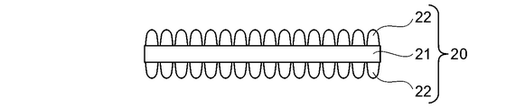
- a film-like member 20 that does not have the base layer 13 and in which the moth-eye structure of the plurality of structures 22 is directly formed on the base 21 may be used.
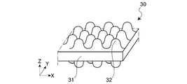
- the base body and the structure may be integrally formed as shown in FIG. 3, for example. That is, in the case of the configuration of FIG. 3, the structural body 32 is integrally formed on both surfaces of the base 31 to form the film-like member 30.
- the substrate 11 will be further described.
- the substrate 11 is a transparent substrate having transparency, for example.
- Examples of the material of the substrate 11 include those containing a plastic material having transparency as a main component, but are not particularly limited to these materials.
- an undercoat layer (not shown) may be further provided by surface treatment in order to further improve the surface energy, coatability, slipperiness, flatness, etc. of the surface of the plastic material.
- the undercoat layer include organoalkoxy metal compounds, polyesters, acrylic-modified polyesters, polyurethanes, and the like.
- the surface of the substrate 11 may be subjected to corona discharge treatment, UV irradiation treatment, or the like.
- the substrate 11 When the substrate 11 is a plastic film, the substrate 11 can be obtained by, for example, a method of stretching the above-mentioned resin or forming a film after being diluted with a solvent and drying.
- the thickness of the substrate 11 is preferably selected as appropriate according to the application of the optical laminate 1, and may be, for example, about 10 ⁇ m or more and 500 ⁇ m or less.
- Examples of the shape of the substrate 11 include a film shape and a plate shape, but are not particularly limited to these shapes.
- a sheet shall be contained in a film.
- Examples of the material of the substrate 11 include methyl methacrylate (co) polymer, polycarbonate, styrene (co) polymer, methyl methacrylate-styrene copolymer, cellulose diacetate, cellulose triacetate, cellulose acetate butyrate, polyester, Examples include, but are not limited to, polyamide, polyimide, polyether sulfone, polysulfone, polypropylene, polymethylpentene, polyvinyl chloride, polyvinyl acetal, polyether ketone, polyurethane, and glass.
- the wavelength band of visible light is 360 nm to 830 nm, but in this embodiment, the structures 12 are regularly arranged with a size equal to or smaller than the wavelength band of visible light. From this viewpoint, it is assumed that the arrangement pitch of the structures 12 does not exceed 350 nm.
- the structure 12 may have various shapes such as a cone shape, a column shape, and a needle shape.
- the structure 12 is formed by curing, for example, an energy ray curable resin composition.
- the energy beam curable resin product forming the structure 12 may have different physical properties on both surfaces of the substrate 11. For example, a function such as anti-fogging can be given to a specific surface by properly using water repellency and hydrophilicity depending on the intended use.
- an ultraviolet curable resin composition is preferably used.
- the energy beam curable resin composition may contain a filler, a functional additive, etc. as needed.
- the ultraviolet curable resin composition contains, for example, an acrylate and an initiator.
- the ultraviolet curable resin composition contains, for example, a monofunctional monomer, a bifunctional monomer, a polyfunctional monomer, and the like, and specifically, is a mixture of the following materials alone or in combination.
- examples of the “monofunctional monomer” include carboxylic acids (acrylic acid), hydroxys (2-hydroxyethyl acrylate, 2-hydroxypropyl acrylate, 4-hydroxybutyl acrylate), alkyl, alicyclics (isobutyl acrylate, t -Butyl acrylate, isooctyl acrylate, lauryl acrylate, stearyl acrylate, isobornyl acrylate, cyclohexyl acrylate), other functional monomers (2-methoxyethyl acrylate, methoxyethylene crycol acrylate, 2-ethoxyethyl acrylate, tetrahydrofurfuryl acrylate, Benzyl acrylate, ethyl carbitol acrylate, phenoxyethyl acrylate, N, N-dimethylaminoethyl acrylate N, N-dimethylaminopropylacrylamide, N, N-di
- bifunctional monomer examples include tri (propylene glycol) diacrylate, trimethylolpropane diallyl ether, urethane acrylate, and the like.
- polyfunctional monomer examples include trimethylolpropane triacrylate, dipentaerythritol penta and hexaacrylate, ditrimethylolpropane tetraacrylate, and the like.
- the “initiator” examples include 2,2-dimethoxy-1,2-diphenylethane-1-one, 1-hydroxy-cyclohexyl phenyl ketone, and 2-hydroxy-2-methyl-1-phenylpropan-1-one. And so on.
- the “filler” for example, both inorganic fine particles and organic fine particles can be used.
- the inorganic fine particles include metal oxide fine particles such as SiO 2 , TiO 2 , ZrO 2 , SnO 2 , and Al 2 O 3 .
- Examples of the “functional additive” include a leveling agent, a surface conditioner, and an antifoaming agent.
- the transparent laminate according to this embodiment includes a plurality of film-like members 10 in which a moth-eye structure composed of a structure 12 with irregularities having a pitch of a visible light wavelength or less is provided on the front and back surfaces of the base body 11, At least an end portion of the film-like member 10 is laminated by the adhesive layer 2 such as an adhesive, and there is a gap 14 between the structures 12 between the laminated film-like members 10.
- the adhesive layer 2 such as an adhesive
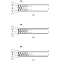
- FIGS. 4 (a) to 4 (c) The gap 14 includes a case where the gap 14 is formed of a resin such as an adhesive. That is, the air gap 14 may be an air layer or a resin layer.
- FIG. 4A shows a case where an air layer is formed without the opposing structures 12 contacting each other due to the thickness of the adhesive layer 2.
- FIG. 4B shows the case where the tips of the opposing structures 12 are in point contact with each other, but the structure 12 is a continuous concavo-convex structure, so that an air layer is formed in the recess.
- FIG. 4C shows a case where a predetermined air layer is formed because the front end of the structural body 12 enters the concave portion of the opposing structural body 12 but does not completely enter. In these cases, each air layer exists as a void. Note that the air gap is not limited to the air layer. For example, when the entire surface of the structure 12 is attached with the adhesive layer 2, the adhesive layer 2 may be included in the air gap in a broad sense.
- the structures 12 are in a regular arrangement, they have regularity when viewed in either the vertical direction or the horizontal direction, so that the stackability is also good.
- the lamination is performed by the adhesive layer 2 such as an adhesive, but in this embodiment, the adhesive layer 2 is provided on the outer peripheral portion that is out of the field of view when worn. That is, it is provided other than the visual recognition part.
- the structures 12 of the film-like member 2 are partially joined to each other by the adhesive layer 2 at the four corners of the film-like member 10 or in regions extending at a predetermined width and a predetermined length in the lateral direction at the left and right ends. It may be.
- the peelability of the film-like member 10 itself is improved, and the release of the adhesive as the pressure-sensitive adhesive layer 2 is achieved. (A reduction in visibility due to residues) is also improved, and the occurrence of distortion due to the thickness of the adhesive as the pressure-sensitive adhesive layer 2 can be avoided.
- the entire surface may be attached with an adhesive or the like.
- the resin composition is appropriately selected so that the refractive index and the like are suitable for improving visibility.
- the transparent laminated body 1 which concerns on this embodiment is a laminated body which has the moth eye structure which implement
- the transparent laminate 1 is bonded to the adherend 4 via the bonding layer 3.
- the adherend include a helmet visor used in auto racing, a medical face shield, a medical display, and protective eyeglasses for painting.
- the present invention is not limited to these, and it is not possible to predict the arrival of pollutants, and in the environment where the visibility must be restored immediately when contaminated, or in the first place the pollutants are dangerous and contact is not desirable.
- Various optical articles used in the above are included.
- the adherend to which the transparent laminated body 1 of FIG. 5 is attached corresponds to an example of the protective equipment of the present embodiment.
- the adhesive layer 3 can use adhesives, such as rubber
- the pressure-sensitive adhesive is a (meth) acrylic acid ester copolymer having a weight average molecular weight of 200,000 to 2,000,000, preferably 500,000 to 2,000,000, and the weight average molecular weight is 50,000 or less and 5% or less. It is good as well. In this case, even if the pressure sensitive adhesive is on the entire surface of the film, there is no practical problem because the peelability is good.
- the transparent laminate according to the embodiment of the present invention is a film in which a plurality of structures 12 are provided on both surfaces of a base 11 as a flexible transparent substrate with a pitch less than the wavelength of visible light.
- the sheet-like member 10 is configured by laminating and laminating a plurality of sheets with a gap between a part of the areas of the film-like member 10 being laminated.
- the contaminated film-like member 10 is not preferable because it is a dangerous substance. Can be removed one by one, so that the field of view can be immediately recovered and it is not necessary to come into contact with dangerous materials.
- such a moth-eye structure is basically compatible with all wavelengths, so when the subject is viewed through the moth-eye structure, There is also an advantage that the color does not change. Moreover, it can be said that the moth-eye structure is suitable for use in an environment where the illuminance jumps abruptly, or in an environment where it takes time until the human eye gets used to the illuminance difference.
- the adhesive layer 2 such as an adhesive
- the immediateness and convenience of peeling can be achieved, and the adhesive There is no distortion caused by the thickness.
- the shield surface is dirty and the film-like member 10 is peeled off, only a part of the area is adhered, so that it can be peeled off with a light force.
- the adhesive layer is provided in a wide area, the difference in the peel force between the end portion and the visual recognition portion is because the peelability by the light force described above is not inhibited.
- the structure provided on the back side of the film-like member is hydrophilic
- the structure provided on the front side is water-repellent
- one film-like member constituting the transparent laminate is provided.
- the adhesive layer such as adhesive remains on the peeled film-like member side, so that the adhesive remains on the surface after peeling and promotes the adhesion of flying contaminants Can also be prevented.
- the film-like members are alternately provided from the right and from the left after removing the film-like members from the left by alternately providing knobs (projections) for removal one by one at the left and right ends of the film-like member. You may comprise so that may be peeled.
- the number of the film-like member 10 may be displayed as a number on the knob portion so that the remaining number of the film-like member 10 can be grasped.
- the adherend to which the transparent laminate according to this embodiment is applied includes a helmet visor used in auto racing, a medical face shield, a medical display, protective glasses for painting, and the like.
- a helmet visor used in auto racing
- a medical face shield used in auto racing
- a medical display used in auto racing
- protective glasses for painting and the like.
- it can also be applied to optical devices such as cameras and telescopes.
- the optical sensitivity such as the refractive index is directly different from that of human beings.
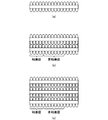
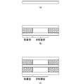
- Example 1 First, several drops of UV curable resin were dropped on a master plate having a moth-eye shape, which is a fine uneven shape below the wavelength of light, and a polycarbonate film as a transparent substrate corresponding to the substrate was covered, and the entire master plate was spread with a roller. . Then, after irradiating the ultraviolet-ray from the polycarbonate film side as a transparent base material and hardening
- FIG. 6A shows the structure of a single layer
- FIG. 6B shows the structure of two laminated layers
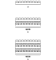
- Example 2 First, several drops of UV curable resin were dropped on a master plate having a moth-eye shape, which is a fine uneven shape below the wavelength of light, and a polycarbonate film as a transparent substrate corresponding to the substrate was covered, and the entire master plate was spread with a roller. . Then, after irradiating the ultraviolet-ray from the polycarbonate film side as a transparent base material and hardening
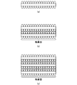
- Comparative Example 1 As Comparative Example 1, a commercially available optical PET film was laminated as an adhesive layer with two or three layers using an adhesive or the like, and three types of transparent laminates including a single layer were obtained. 8A shows the structure of a single layer, FIG. 8B shows the structure of two layers, and FIG. 8C shows the structure of a transparent layered structure of three layers. In this example, since the adhesive layer is provided only at the end of the optical PET film, the gap is divided into an adhesive surface and a non-adhesive surface.
- FIG. 11 shows how this result is illustrated.
- the transmittance of the n-layer structure can be regarded as approximately n times the transmittance in the case of a single layer.
- Example 1 from Table 1 and FIG. 9, even when three sheets are stacked, the transmittance is very high, and the transmittance more than the transmittance of the single layers of Examples 2, 3 and Comparative Example 1 can be secured. It became clear that That is, for example, the transmittance of the single layer of Example 2 is 95.29%, whereas in Example 1, the two-layer lamination is 99.13% and the three-layer lamination is 98.85% on the bonding surface. In the non-adhesive surface, the number of single layers in Examples 2 and 3 and Comparative Example 1 is 95.74%. It was clear that the good transmittance was maintained.
- the required luminous transmittance of the JIS standard is 85% or more, but as is apparent from FIG. It can be seen that the transmittance is satisfied. This means that the range of application to standard products is wide.
- the reflectance as shown in Table 2 and FIG. 11, even in the case of two-layer lamination and three-layer lamination, both the adhesive surface and the non-adhesive surface are good results of less than 4%.
- Example 2 as shown in Table 1 and FIGS. 9 and 10, the transmittance of the single layer of Comparative Example 1 was obtained even in the case of two-layer lamination, three-layer lamination, and twenty-sheet lamination on the bonding surface. The above transmittance can be secured. However, in Example 2, the transmittance on the non-adhesive surface drops by about 4% every time one layer increases, and some influence due to reflection on the surface without the fine structure is seen.
- Comparative Example 1 there is an influence of reflection at both interfaces of the film, and the transmittance in a state where three sheets are stacked is 79% on the non-adhesive surface. This does not satisfy the required luminous transmittance of 85% of the JIS standard (JIS T8147 protective glasses), and it can be said that the adverse effect on the visual field when it is applied to an actual shield is remarkable.
- Example 3 Hereafter, each procedure of preparation of a nanostructure sheet
- PC polycarbonate
- FIG. 12A shows the structure of a single layer
- FIG. 12B shows the configuration of two laminated layers
- FIG. 12C shows the configuration of a transparent laminate of three stacked layers.
- the pressure-sensitive adhesive used when laminating a plurality of sheets is provided over the entire surface of the film-like member.
- Example 4 to 8 were produced in the same manner as in Example 3 described above except that the resin composition was different as described in detail later.
- Example 3 A pressure-sensitive adhesive was produced in the same manner as in Example 3 except that a resin obtained by solution polymerization instead of living polymerization was used, and a transparent laminate was produced in the same manner as in Example 3.
- Tt total light transmittance
- peel strength of adhesive With respect to the peel strength between the nanostructure support and the nanostructure, the load when peeled at a peel angle of 90 ° and a peel speed of 300 mm / min was determined using a tensile tester.
- Table 4 shows the contents of the pressure-sensitive adhesive used in the transparent laminates of Examples 3 to 8 and the type of the crosslinking agent.
- a crosslinking agent is included in an adhesive.
- FIG. 13 (a) to 13 (c) show a transparent laminated body that is a laminated body through a pressure-sensitive adhesive layer of a film-like member having a moth-eye shape on both sides, which is produced by the same method as in Example 1 of the present invention. It is a figure which shows another structure. That is, FIG. 13A shows the structure of a single layer, FIG. 13B shows the configuration of two laminated layers, and FIG. The adhesive used when laminating a plurality of sheets is provided over the entire surface of the film-like member. Thus, even with a transparent laminate having a moth-eye shape on both sides created by the same method as in Example 1, the effect can be obtained without problems.
- the transparent support, the base provided with a plurality of structures at a pitch equal to or less than the wavelength of visible light on at least one surface, and another base are laminated with an adhesive.
- a (meth) acrylic acid ester copolymer having a weight average molecular weight of 200,000 to 2,000,000 is used as an adhesive, and the weight average molecular weight is 50,000 or less and 5% or less. It became clear that this was preferable.
- By using such an adhesive it is possible to suppress changes in adhesive residue / peeling force over time on the nanostructure.
- a plurality of film-like members may be laminated and laminated, and one film-like member may have a gap between some of the areas of the film-like member, and the remaining area
- a plurality of laminates may be laminated using a pressure-sensitive adhesive capable of peeling between layers.
- the low molecular weight component having a weight average molecular weight of 50,000 or less of the pressure-sensitive adhesive may be 2 parts by weight or less.
- a plurality of film-like members may be laminated and bonded using an ultrasonic welding method or a heat welding method.
Landscapes
- Physics & Mathematics (AREA)
- General Physics & Mathematics (AREA)
- Optics & Photonics (AREA)
- Laminated Bodies (AREA)
- Helmets And Other Head Coverings (AREA)
Abstract
La présente invention a pour objet d'empêcher une augmentation de la réflectance et une diminution de la transmittance, de conserver l'instantanéité intacte et la facilité de décapage, d'améliorer l'aptitude au décollement de l'adhésif, d'éviter la génération de distorsion du fait de l'épaisseur de l'adhésif, et d'assurer la visibilité, en stratifiant des éléments pelliculaires (10) dont chacun est équipé d'une structure (12) en œil de lépidoptère. Ce stratifié transparent (1) comporte une pluralité d'éléments pelliculaires (10) dont chacun comporte un socle (11) et, disposé sur au moins une de ses surfaces, une structure (12) constituée de creux et de protubérances qui ont été agencés régulièrement à un pas qui n'est pas supérieur aux longueurs d'ondes de la lumière visible. Au moins les extrémités des éléments pelliculaires (10) ont été superposées, une couche (2) d'adhésif autocollant étant interposée entre celles-ci. Dans les éléments pelliculaires (10) superposés, un espace (14) est ménagé entre les structures (12) opposées.
Priority Applications (2)
| Application Number | Priority Date | Filing Date | Title |
|---|---|---|---|
| US14/910,598 US10000037B2 (en) | 2013-08-09 | 2014-06-04 | Transparent laminate and protective tool including the same |
| EP14834273.6A EP3031602B1 (fr) | 2013-08-09 | 2014-06-04 | Stratifié transparent et outil protecteur le comprenant |
Applications Claiming Priority (4)
| Application Number | Priority Date | Filing Date | Title |
|---|---|---|---|
| JP2013165708 | 2013-08-09 | ||
| JP2013-165708 | 2013-08-09 | ||
| JP2014069558A JP6493900B2 (ja) | 2013-08-09 | 2014-03-28 | 透明積層体、及びそれを用いた保護具 |
| JP2014-069558 | 2014-03-28 |
Publications (1)
| Publication Number | Publication Date |
|---|---|
| WO2015019529A1 true WO2015019529A1 (fr) | 2015-02-12 |
Family
ID=52460893
Family Applications (1)
| Application Number | Title | Priority Date | Filing Date |
|---|---|---|---|
| PCT/JP2014/002980 Ceased WO2015019529A1 (fr) | 2013-08-09 | 2014-06-04 | Stratifié transparent et outil protecteur le comprenant |
Country Status (4)
| Country | Link |
|---|---|
| US (1) | US10000037B2 (fr) |
| EP (1) | EP3031602B1 (fr) |
| JP (1) | JP6493900B2 (fr) |
| WO (1) | WO2015019529A1 (fr) |
Cited By (3)
| Publication number | Priority date | Publication date | Assignee | Title |
|---|---|---|---|---|
| KR20210072042A (ko) * | 2018-11-08 | 2021-06-16 | 데쿠세리아루즈 가부시키가이샤 | 적층체, 적층체의 제조 방법, 광학체의 형성 방법 및 카메라 모듈 탑재 장치 |
| WO2022054933A1 (fr) * | 2020-09-11 | 2022-03-17 | 大日本印刷株式会社 | Film stratifié transparent, film stratifié transparent avec film de protection et écran facial |
| JP7669705B2 (ja) | 2021-01-28 | 2025-04-30 | 大日本印刷株式会社 | 透明積層フィルム、保護フィルム付き透明積層フィルムおよびフェイスシールド |
Families Citing this family (9)
| Publication number | Priority date | Publication date | Assignee | Title |
|---|---|---|---|---|
| JP6684046B2 (ja) * | 2014-07-30 | 2020-04-22 | デクセリアルズ株式会社 | 透明積層体 |
| US11585962B2 (en) * | 2018-10-19 | 2023-02-21 | Racing Optics, Inc. | Transparent covering having anti-reflective coatings |
| US11635622B1 (en) * | 2018-12-07 | 2023-04-25 | Meta Platforms Technologies, Llc | Nanovided spacer materials and corresponding systems and methods |
| JP7816149B2 (ja) | 2020-06-30 | 2026-02-18 | 大日本印刷株式会社 | 透明積層体、画像表示装置、両面反射防止積層体、および顔用透明保護具 |
| US11708150B2 (en) | 2021-02-09 | 2023-07-25 | Safran Landing Systems Canada Inc. | Hybrid main landing gear fitting with detachable drag arm |
| US12140781B2 (en) | 2021-07-27 | 2024-11-12 | Laminated Film Llc | Low reflectance removable lens stack |
| US11307329B1 (en) | 2021-07-27 | 2022-04-19 | Racing Optics, Inc. | Low reflectance removable lens stack |
| JP7791771B2 (ja) | 2022-05-19 | 2025-12-24 | デクセリアルズ株式会社 | フィルム積層体、フィルム積層体の製造方法、保護具、保護具の製造方法 |
| JP2023170535A (ja) | 2022-05-19 | 2023-12-01 | デクセリアルズ株式会社 | フィルム積層体、フィルム積層体の製造方法、保護具、保護具の製造方法 |
Citations (18)
| Publication number | Priority date | Publication date | Assignee | Title |
|---|---|---|---|---|
| US5002326A (en) * | 1990-01-22 | 1991-03-26 | Westfield William R | Automotive windshield laminated protector |
| US5592698A (en) * | 1995-06-30 | 1997-01-14 | Woods; Marlen M. | Tear-off lens for transparent eye and face shield |
| JP2000192322A (ja) | 1998-12-24 | 2000-07-11 | Teac Corp | ヘルメットのシールド部分の保護装置 |
| JP2002528298A (ja) * | 1998-10-28 | 2002-09-03 | スリーエム イノベイティブ プロパティズ カンパニー | 剥離可能なシートを有する落書き防止および/または環境保護物品、それにより保護された基板、並びに使用方法 |
| JP2003222701A (ja) * | 2002-01-29 | 2003-08-08 | Seiko Epson Corp | 光学部品及びその製造方法 |
| WO2004000540A2 (fr) * | 2002-06-24 | 2003-12-31 | Bart Wilson | Empilement optique de lentilles amovibles en verre feuillete |
| US6847492B2 (en) * | 1999-11-24 | 2005-01-25 | Bart Wilson | Optical stack of laminated removable lenses for face shields, windows, and displays |
| US20050015860A1 (en) * | 2003-06-19 | 2005-01-27 | Reaux Brian K. | Face and eye covering device |
| JP2010048902A (ja) | 2008-08-19 | 2010-03-04 | The Inctec Inc | 低反射透明板及びそれを用いた展示用ケース |
| WO2010073881A1 (fr) * | 2008-12-25 | 2010-07-01 | シャープ株式会社 | Cuve de stockage de liquide, outil d'observation dans le liquide et film optique |
| WO2011027909A1 (fr) * | 2009-09-02 | 2011-03-10 | ソニー株式会社 | Élément optique conducteur, panneau tactile, dispositif d'entrée d'informations, dispositif d'affichage, cellule solaire et dessin maître pour la production d'élément optique conducteur |
| WO2011149948A1 (fr) * | 2010-05-24 | 2011-12-01 | Astic Signals Defenses Llc | Ecrans protecteurs transparents, biodégradables, et utilisations associées |
| JP4849183B1 (ja) * | 2010-08-05 | 2012-01-11 | 大日本印刷株式会社 | 反射防止フィルム製造用金型の製造方法 |
| JP2012086515A (ja) | 2010-10-22 | 2012-05-10 | Sony Corp | 積層体、成型素子、および光学素子 |
| JP3178509U (ja) * | 2012-06-26 | 2012-09-20 | 章 富岡 | 使い捨て透明フィルム付きメガネ |
| WO2013081145A1 (fr) * | 2011-12-02 | 2013-06-06 | シャープ株式会社 | Stratifié |
| JP2013195579A (ja) * | 2012-03-16 | 2013-09-30 | Sony Corp | 積層体およびその製造方法、透明基材、表示装置、入力装置ならびに電子機器 |
| WO2014112555A1 (fr) * | 2013-01-17 | 2014-07-24 | デクセリアルズ株式会社 | Élément optique pour protection faciale |
Family Cites Families (17)
| Publication number | Priority date | Publication date | Assignee | Title |
|---|---|---|---|---|
| US2511329A (en) * | 1946-12-26 | 1950-06-13 | Craig Edward | Lens shield |
| US3904281A (en) * | 1969-12-08 | 1975-09-09 | Optical Sciences Group Inc | Flexible refracting membrane adhered to spectacle lens |
| JP2698799B2 (ja) * | 1991-09-20 | 1998-01-19 | セイコープレシジョン株式会社 | インクジェットヘッド |
| US5502516A (en) * | 1994-03-11 | 1996-03-26 | Elterman; Warren B. | Disposable/reusable sun filter |
| JPH0966606A (ja) * | 1995-08-31 | 1997-03-11 | Seikosha Co Ltd | インクジェットヘッドの製造方法 |
| KR100660384B1 (ko) * | 1998-03-17 | 2006-12-21 | 세이코 엡슨 가부시키가이샤 | 표시장치의 제조방법 |
| JP3870562B2 (ja) * | 1998-07-16 | 2007-01-17 | セイコーエプソン株式会社 | パターン形成方法、およびパターン形成基板の製造方法 |
| US8054416B2 (en) * | 2000-08-15 | 2011-11-08 | Reflexite Corporation | Light polarizer |
| JP4269769B2 (ja) | 2003-05-07 | 2009-05-27 | ソニー株式会社 | バッテリパック及び電子機器 |
| AU2006226849B2 (en) * | 2005-03-24 | 2012-08-23 | Stryker Corporation | Personal protection system for fitting over a head and a neck |
| KR100831558B1 (ko) * | 2005-11-18 | 2008-05-21 | 주식회사 엘지화학 | 편광판용 아크릴계 점착제 조성물 |
| JP5170495B2 (ja) * | 2006-03-20 | 2013-03-27 | 日産自動車株式会社 | 反射防止微細構造及び反射防止構造体 |
| US9122002B2 (en) * | 2009-08-05 | 2015-09-01 | Sharp Kabushiki Kaisha | Tabular member and structure with observation port |
| JP4626721B1 (ja) * | 2009-09-02 | 2011-02-09 | ソニー株式会社 | 透明導電性電極、タッチパネル、情報入力装置、および表示装置 |
| GB2485522B (en) * | 2010-10-11 | 2012-10-31 | Fu-Yi Hsu | Screen protective sticker structure |
| JP2012212080A (ja) * | 2011-03-31 | 2012-11-01 | Sumitomo Chemical Co Ltd | 偏光板 |
| TWI537357B (zh) * | 2011-06-11 | 2016-06-11 | Toagosei Co Ltd | Plastic film or sheet with active high-energy radiation hardening adhesive composition (b) |
-
2014
- 2014-03-28 JP JP2014069558A patent/JP6493900B2/ja active Active
- 2014-06-04 EP EP14834273.6A patent/EP3031602B1/fr active Active
- 2014-06-04 WO PCT/JP2014/002980 patent/WO2015019529A1/fr not_active Ceased
- 2014-06-04 US US14/910,598 patent/US10000037B2/en active Active
Patent Citations (19)
| Publication number | Priority date | Publication date | Assignee | Title |
|---|---|---|---|---|
| US5002326A (en) * | 1990-01-22 | 1991-03-26 | Westfield William R | Automotive windshield laminated protector |
| US5592698A (en) * | 1995-06-30 | 1997-01-14 | Woods; Marlen M. | Tear-off lens for transparent eye and face shield |
| JP2002528298A (ja) * | 1998-10-28 | 2002-09-03 | スリーエム イノベイティブ プロパティズ カンパニー | 剥離可能なシートを有する落書き防止および/または環境保護物品、それにより保護された基板、並びに使用方法 |
| JP2000192322A (ja) | 1998-12-24 | 2000-07-11 | Teac Corp | ヘルメットのシールド部分の保護装置 |
| US6847492B2 (en) * | 1999-11-24 | 2005-01-25 | Bart Wilson | Optical stack of laminated removable lenses for face shields, windows, and displays |
| US7184217B2 (en) * | 1999-11-24 | 2007-02-27 | Bart Wilson | Optical stack of laminated removable lenses for face shield, windows, and displays |
| JP2003222701A (ja) * | 2002-01-29 | 2003-08-08 | Seiko Epson Corp | 光学部品及びその製造方法 |
| WO2004000540A2 (fr) * | 2002-06-24 | 2003-12-31 | Bart Wilson | Empilement optique de lentilles amovibles en verre feuillete |
| US20050015860A1 (en) * | 2003-06-19 | 2005-01-27 | Reaux Brian K. | Face and eye covering device |
| JP2010048902A (ja) | 2008-08-19 | 2010-03-04 | The Inctec Inc | 低反射透明板及びそれを用いた展示用ケース |
| WO2010073881A1 (fr) * | 2008-12-25 | 2010-07-01 | シャープ株式会社 | Cuve de stockage de liquide, outil d'observation dans le liquide et film optique |
| WO2011027909A1 (fr) * | 2009-09-02 | 2011-03-10 | ソニー株式会社 | Élément optique conducteur, panneau tactile, dispositif d'entrée d'informations, dispositif d'affichage, cellule solaire et dessin maître pour la production d'élément optique conducteur |
| WO2011149948A1 (fr) * | 2010-05-24 | 2011-12-01 | Astic Signals Defenses Llc | Ecrans protecteurs transparents, biodégradables, et utilisations associées |
| JP4849183B1 (ja) * | 2010-08-05 | 2012-01-11 | 大日本印刷株式会社 | 反射防止フィルム製造用金型の製造方法 |
| JP2012086515A (ja) | 2010-10-22 | 2012-05-10 | Sony Corp | 積層体、成型素子、および光学素子 |
| WO2013081145A1 (fr) * | 2011-12-02 | 2013-06-06 | シャープ株式会社 | Stratifié |
| JP2013195579A (ja) * | 2012-03-16 | 2013-09-30 | Sony Corp | 積層体およびその製造方法、透明基材、表示装置、入力装置ならびに電子機器 |
| JP3178509U (ja) * | 2012-06-26 | 2012-09-20 | 章 富岡 | 使い捨て透明フィルム付きメガネ |
| WO2014112555A1 (fr) * | 2013-01-17 | 2014-07-24 | デクセリアルズ株式会社 | Élément optique pour protection faciale |
Non-Patent Citations (1)
| Title |
|---|
| See also references of EP3031602A4 |
Cited By (4)
| Publication number | Priority date | Publication date | Assignee | Title |
|---|---|---|---|---|
| KR20210072042A (ko) * | 2018-11-08 | 2021-06-16 | 데쿠세리아루즈 가부시키가이샤 | 적층체, 적층체의 제조 방법, 광학체의 형성 방법 및 카메라 모듈 탑재 장치 |
| KR102603101B1 (ko) | 2018-11-08 | 2023-11-17 | 데쿠세리아루즈 가부시키가이샤 | 적층체, 적층체의 제조 방법, 광학체의 형성 방법 및 카메라 모듈 탑재 장치 |
| WO2022054933A1 (fr) * | 2020-09-11 | 2022-03-17 | 大日本印刷株式会社 | Film stratifié transparent, film stratifié transparent avec film de protection et écran facial |
| JP7669705B2 (ja) | 2021-01-28 | 2025-04-30 | 大日本印刷株式会社 | 透明積層フィルム、保護フィルム付き透明積層フィルムおよびフェイスシールド |
Also Published As
| Publication number | Publication date |
|---|---|
| US20160193808A1 (en) | 2016-07-07 |
| EP3031602A4 (fr) | 2017-04-26 |
| US10000037B2 (en) | 2018-06-19 |
| EP3031602B1 (fr) | 2020-12-30 |
| JP2015057317A (ja) | 2015-03-26 |
| EP3031602A1 (fr) | 2016-06-15 |
| JP6493900B2 (ja) | 2019-04-03 |
Similar Documents
| Publication | Publication Date | Title |
|---|---|---|
| JP6493900B2 (ja) | 透明積層体、及びそれを用いた保護具 | |
| JP6750188B2 (ja) | マスターフィルム付きナノ構造フィルム及びその製造方法 | |
| TWI680869B (zh) | 顏面保護罩用透明膜 | |
| JP5412321B2 (ja) | 透明性に優れた離型フィルム | |
| JP6469965B2 (ja) | 眼鏡用保護具 | |
| JP6655239B2 (ja) | 透明積層体、及びそれを用いた保護具 | |
| JP6609402B2 (ja) | 光学フィルム及びその製造方法 | |
| WO2010113868A1 (fr) | Dispositif d'affichage et film optique | |
| JP6018397B2 (ja) | 情報表示面用の両面粘着シート,情報表示面の保護シート,及び前記両面粘着シート及び保護シートの製造方法 | |
| KR101321341B1 (ko) | 터치스크린 패널 보호용 필터 | |
| KR101840992B1 (ko) | 투명한 점착제층을 갖는 도전성 필름 적층체 | |
| JP2012027260A (ja) | 偏光シート積層体 | |
| JPWO2013172448A1 (ja) | フィルムとその製造方法、板状物、画像表示装置、太陽電池 | |
| JP2013195579A (ja) | 積層体およびその製造方法、透明基材、表示装置、入力装置ならびに電子機器 | |
| TWI740932B (zh) | 觸控面板、顯示裝置、光學片及光學片的篩選方法 | |
| WO2021200678A1 (fr) | Stratifié de film antireflet et produit pourvu dudit stratifié | |
| JP2013107281A (ja) | 積層体 | |
| JP6923293B2 (ja) | 微細凹凸構造体および接合体 | |
| KR101819437B1 (ko) | 투명한 점착제층을 갖는 도전성 필름 적층체 | |
| JP6938455B2 (ja) | 眼鏡装着者用保護具 |
Legal Events
| Date | Code | Title | Description |
|---|---|---|---|
| 121 | Ep: the epo has been informed by wipo that ep was designated in this application |
Ref document number: 14834273 Country of ref document: EP Kind code of ref document: A1 |
|
| DPE1 | Request for preliminary examination filed after expiration of 19th month from priority date (pct application filed from 20040101) | ||
| WWE | Wipo information: entry into national phase |
Ref document number: 14910598 Country of ref document: US |
|
| NENP | Non-entry into the national phase |
Ref country code: DE |
|
| WWE | Wipo information: entry into national phase |
Ref document number: 2014834273 Country of ref document: EP |