WO2015019683A1 - Dispositif d'éclairage et lentille de distribution de lumière large - Google Patents
Dispositif d'éclairage et lentille de distribution de lumière large Download PDFInfo
- Publication number
- WO2015019683A1 WO2015019683A1 PCT/JP2014/063913 JP2014063913W WO2015019683A1 WO 2015019683 A1 WO2015019683 A1 WO 2015019683A1 JP 2014063913 W JP2014063913 W JP 2014063913W WO 2015019683 A1 WO2015019683 A1 WO 2015019683A1
- Authority
- WO
- WIPO (PCT)
- Prior art keywords
- point
- optical element
- central axis
- light distribution
- distribution lens
- Prior art date
- Legal status (The legal status is an assumption and is not a legal conclusion. Google has not performed a legal analysis and makes no representation as to the accuracy of the status listed.)
- Ceased
Links
Images


Classifications
-
- G—PHYSICS
- G02—OPTICS
- G02B—OPTICAL ELEMENTS, SYSTEMS OR APPARATUS
- G02B19/00—Condensers, e.g. light collectors or similar non-imaging optics
- G02B19/0033—Condensers, e.g. light collectors or similar non-imaging optics characterised by the use
- G02B19/0047—Condensers, e.g. light collectors or similar non-imaging optics characterised by the use for use with a light source
- G02B19/0061—Condensers, e.g. light collectors or similar non-imaging optics characterised by the use for use with a light source the light source comprising a LED
-
- F—MECHANICAL ENGINEERING; LIGHTING; HEATING; WEAPONS; BLASTING
- F21—LIGHTING
- F21V—FUNCTIONAL FEATURES OR DETAILS OF LIGHTING DEVICES OR SYSTEMS THEREOF; STRUCTURAL COMBINATIONS OF LIGHTING DEVICES WITH OTHER ARTICLES, NOT OTHERWISE PROVIDED FOR
- F21V13/00—Producing particular characteristics or distribution of the light emitted by means of a combination of elements specified in two or more of main groups F21V1/00 - F21V11/00
- F21V13/02—Combinations of only two kinds of elements
-
- F—MECHANICAL ENGINEERING; LIGHTING; HEATING; WEAPONS; BLASTING
- F21—LIGHTING
- F21V—FUNCTIONAL FEATURES OR DETAILS OF LIGHTING DEVICES OR SYSTEMS THEREOF; STRUCTURAL COMBINATIONS OF LIGHTING DEVICES WITH OTHER ARTICLES, NOT OTHERWISE PROVIDED FOR
- F21V3/00—Globes; Bowls; Cover glasses
- F21V3/02—Globes; Bowls; Cover glasses characterised by the shape
-
- F—MECHANICAL ENGINEERING; LIGHTING; HEATING; WEAPONS; BLASTING
- F21—LIGHTING
- F21V—FUNCTIONAL FEATURES OR DETAILS OF LIGHTING DEVICES OR SYSTEMS THEREOF; STRUCTURAL COMBINATIONS OF LIGHTING DEVICES WITH OTHER ARTICLES, NOT OTHERWISE PROVIDED FOR
- F21V5/00—Refractors for light sources
- F21V5/04—Refractors for light sources of lens shape
-
- F—MECHANICAL ENGINEERING; LIGHTING; HEATING; WEAPONS; BLASTING
- F21—LIGHTING
- F21V—FUNCTIONAL FEATURES OR DETAILS OF LIGHTING DEVICES OR SYSTEMS THEREOF; STRUCTURAL COMBINATIONS OF LIGHTING DEVICES WITH OTHER ARTICLES, NOT OTHERWISE PROVIDED FOR
- F21V7/00—Reflectors for light sources
- F21V7/0091—Reflectors for light sources using total internal reflection
-
- G—PHYSICS
- G02—OPTICS
- G02B—OPTICAL ELEMENTS, SYSTEMS OR APPARATUS
- G02B19/00—Condensers, e.g. light collectors or similar non-imaging optics
- G02B19/0004—Condensers, e.g. light collectors or similar non-imaging optics characterised by the optical means employed
- G02B19/0028—Condensers, e.g. light collectors or similar non-imaging optics characterised by the optical means employed refractive and reflective surfaces, e.g. non-imaging catadioptric systems
-
- F—MECHANICAL ENGINEERING; LIGHTING; HEATING; WEAPONS; BLASTING
- F21—LIGHTING
- F21K—NON-ELECTRIC LIGHT SOURCES USING LUMINESCENCE; LIGHT SOURCES USING ELECTROCHEMILUMINESCENCE; LIGHT SOURCES USING CHARGES OF COMBUSTIBLE MATERIAL; LIGHT SOURCES USING SEMICONDUCTOR DEVICES AS LIGHT-GENERATING ELEMENTS; LIGHT SOURCES NOT OTHERWISE PROVIDED FOR
- F21K9/00—Light sources using semiconductor devices as light-generating elements, e.g. using light-emitting diodes [LED] or lasers
- F21K9/20—Light sources comprising attachment means
- F21K9/23—Retrofit light sources for lighting devices with a single fitting for each light source, e.g. for substitution of incandescent lamps with bayonet or threaded fittings
- F21K9/232—Retrofit light sources for lighting devices with a single fitting for each light source, e.g. for substitution of incandescent lamps with bayonet or threaded fittings specially adapted for generating an essentially omnidirectional light distribution, e.g. with a glass bulb
-
- F—MECHANICAL ENGINEERING; LIGHTING; HEATING; WEAPONS; BLASTING
- F21—LIGHTING
- F21K—NON-ELECTRIC LIGHT SOURCES USING LUMINESCENCE; LIGHT SOURCES USING ELECTROCHEMILUMINESCENCE; LIGHT SOURCES USING CHARGES OF COMBUSTIBLE MATERIAL; LIGHT SOURCES USING SEMICONDUCTOR DEVICES AS LIGHT-GENERATING ELEMENTS; LIGHT SOURCES NOT OTHERWISE PROVIDED FOR
- F21K9/00—Light sources using semiconductor devices as light-generating elements, e.g. using light-emitting diodes [LED] or lasers
- F21K9/20—Light sources comprising attachment means
- F21K9/23—Retrofit light sources for lighting devices with a single fitting for each light source, e.g. for substitution of incandescent lamps with bayonet or threaded fittings
- F21K9/238—Arrangement or mounting of circuit elements integrated in the light source
-
- F—MECHANICAL ENGINEERING; LIGHTING; HEATING; WEAPONS; BLASTING
- F21—LIGHTING
- F21K—NON-ELECTRIC LIGHT SOURCES USING LUMINESCENCE; LIGHT SOURCES USING ELECTROCHEMILUMINESCENCE; LIGHT SOURCES USING CHARGES OF COMBUSTIBLE MATERIAL; LIGHT SOURCES USING SEMICONDUCTOR DEVICES AS LIGHT-GENERATING ELEMENTS; LIGHT SOURCES NOT OTHERWISE PROVIDED FOR
- F21K9/00—Light sources using semiconductor devices as light-generating elements, e.g. using light-emitting diodes [LED] or lasers
- F21K9/60—Optical arrangements integrated in the light source, e.g. for improving the colour rendering index or the light extraction
- F21K9/69—Details of refractors forming part of the light source
-
- F—MECHANICAL ENGINEERING; LIGHTING; HEATING; WEAPONS; BLASTING
- F21—LIGHTING
- F21Y—INDEXING SCHEME ASSOCIATED WITH SUBCLASSES F21K, F21L, F21S and F21V, RELATING TO THE FORM OR THE KIND OF THE LIGHT SOURCES OR OF THE COLOUR OF THE LIGHT EMITTED
- F21Y2105/00—Planar light sources
-
- F—MECHANICAL ENGINEERING; LIGHTING; HEATING; WEAPONS; BLASTING
- F21—LIGHTING
- F21Y—INDEXING SCHEME ASSOCIATED WITH SUBCLASSES F21K, F21L, F21S and F21V, RELATING TO THE FORM OR THE KIND OF THE LIGHT SOURCES OR OF THE COLOUR OF THE LIGHT EMITTED
- F21Y2115/00—Light-generating elements of semiconductor light sources
- F21Y2115/10—Light-emitting diodes [LED]
Definitions
- Embodiments of the present invention relate to a lighting device and a wide light distribution lens.
- ⁇ LED (Light-emitting Diode) lamps for general lighting have strong light directivity and a narrow light distribution angle of about 120 °. For this reason, there exists a subject that the way of the spreading
- an LED lamp in which a wide light distribution lens is arranged on a COB (Chip On Board) type light emitting module (hereinafter also referred to as a light emitting element) is known.
- the conventional wide light distribution lens includes an incident surface, a first exit surface facing the entrance surface, and a second exit surface connecting the outer periphery of the entrance surface and the outer periphery of the first exit surface. And.
- the first exit surface has a shape that is recessed in a conical shape toward the center of the entrance surface, and the tip of the cone is positioned on the optical axis passing through the center of the entrance surface.
- the second exit surface surrounds the optical axis coaxially and extends in the radial direction of the optical axis from the outer periphery of the entrance surface toward the outer periphery of the first exit surface.
- the light from the light emitting element When the light from the light emitting element is incident on the incident surface of the wide light distribution lens, a part of the incident light is totally reflected by the first exit surface and travels toward the second exit surface, and further the second exit surface. Radiated from the surface toward the side and rear of the wide light distribution lens. Therefore, the light emitted from the second emission surface becomes a light distribution component toward the rear of the LED lamp, and the light distribution angle of the LED lamp is widened.
- the second exit surface that diffuses light toward the side and rear of the LED lamp has a central axis from the outer peripheral edge of the incident surface toward the outer peripheral edge of the first output surface. It spreads in the radial direction.
- the wide light distribution lens is increased in size, and even if this wide light distribution lens is applied to a small LED lamp having a glove having a shape similar to a chandelier sphere, for example, The lens can no longer fit in the glove.
- This embodiment provides a wide light distribution lens and a proof device that can be made compact while sufficiently securing a light distribution angle.
- the wide light distribution lens according to the present embodiment is a first optical element having a rotationally symmetric shape with respect to a central axis and transparent to visible light, wherein the first optical element includes a first portion, A second portion connected to the first portion, the first portion including a bottom surface having one of a concave surface and a flat surface, and a side surface connected to the bottom surface;
- the portion has an upper surface and a side surface connected to the upper surface, the side surface of the first portion and the side surface of the second portion are connected by a bonding surface having the same size and shape, and the bonding surface is A first optical element larger than the bottom surface,
- a surface light source having a light emitting surface having a circular first region having a center intersecting the central axis and a second region outside the first region is disposed to face the bottom surface of the first portion.
- the side surface of the first portion is a point on the light emitting surface.
- the angle ⁇ P formed by the first vector from the first point toward the second point is configured to be larger than the total reflection angle ⁇ C in the first portion
- the side surface of the second portion is such that the third point on the side surface is the center of the points on the light emitting surface.
- the angle ⁇ Q formed by the vector from the point to the fourth point is configured to be larger than the total reflection angle ⁇ C in the second part.
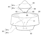
- the bird's-eye view which shows the wide light distribution lens which concerns on 1st Embodiment.
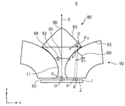
- Sectional drawing which shows the illuminating device by 1st Embodiment.
- the bird's-eye view which shows the illuminating device by 2nd Embodiment.
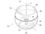
- the bird's-eye view which shows the wide light distribution lens which concerns on 2nd Embodiment.
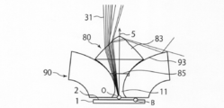
- Sectional drawing which shows the illuminating device by 2nd Embodiment Sectional drawing explaining the function of the illuminating device of 2nd Embodiment. Sectional drawing explaining the function of the illuminating device of 2nd Embodiment. Sectional drawing explaining the function of the illuminating device of 2nd Embodiment. Sectional drawing explaining the function of the illuminating device of 2nd Embodiment. Sectional drawing explaining the function of the illuminating device of 2nd Embodiment.
- the bird's-eye view which shows the illuminating device by 3rd Embodiment.
- the bird's-eye view which shows the wide light distribution lens which concerns on 3rd Embodiment.
- the illumination device includes a light emitting module (light emitting element) and a wide light distribution lens.
- a light emitting module light emitting element
- a wide light distribution lens A bird's-eye view of this wide light distribution lens is shown in FIG.
- This wide light distribution lens includes an optical element 80, a joining column 82, and a basic optical element 90.
- the basic optical element 90 includes a first portion 91a and a second portion 91b connected to the first portion.
- the bottom surface of the first portion 91a is flat and serves as an incident surface on which light from the light emitting element is incident.
- the side surface of the first portion 91a is in contact with the side surface of the second portion 91b and is connected by a joint surface having the same size and shape, and this joint surface is larger than the incident surface.
- the joint surface means a cross section cut along a plane orthogonal to the central axis.
- the side surface of the first portion 91a has a shape that is recessed toward the central axis of the first portion 91a.
- the first portion 91a has a cross-sectional area that increases from the bottom surface toward the joint surface, that is, from the bottom to the top, and the side surface is recessed toward the central axis of the first portion 91a. It has a shape.
- “upward” and “downward” correspond to the positive and negative directions of the central axis 5, respectively.
- the positive direction is a direction in which light is extracted from the light emitting module.
- a cross-sectional area means the area cut
- the upper surface (total reflection surface) 93 of the second portion 91b has a shape that is recessed toward the central axis, and the side surface has a tapered shape in which the cross-sectional area of the second portion 91b decreases from the bottom to the top.
- a through hole 11 is provided in the central portion of the basic optical element 90 along the central axis.
- the through-hole 11 has a shape in which the cross-sectional area decreases as it goes upward from the incident surface 92 in the first portion 91a, and the shape in which the cross-sectional area increases in the second portion 91b as it goes upward from below. have.
- Light that has entered the through hole 11 from a light emitting element (not shown) travels straight, and light that has entered the first portion 91 a without passing through the through hole 11 is totally reflected by the upper surface (total reflection surface) 93.
- the optical element 80 includes a first portion 81a and a second portion 81b connected to the first portion 81a.
- the bottom surface 85 of the first portion 81 a is a concave surface
- the side surface 84 is a connection surface connected to the total reflection surface 93 of the basic optical element 90.
- the side surface 84 of the first portion 81a and the side surface 83 of the second portion 81b are connected by a joint surface having the same size and shape, and this joint surface is larger than the bottom surface.
- the side surface 83 of the second portion 81b is a total reflection / refractive transmission surface that totally reflects or refracts and transmits light that has passed through the optical element 80.
- the upper surface (the surface on the positive direction side of the central axis) of the second portion 81b is connected to the side surface 83 and has a shape that protrudes toward the center.
- the joining column 82 is provided on the side surface of the first portion 81a.
- the optical element 80 and the basic optical element 90 are bonded by the bonding column 82.
- the surface of the joining column 82 in contact with the basic optical element 90 may be adhered with an adhesive or the like.
- the length of the column of the joining column 82 is determined so that an air layer is formed between the optical element 80 and the basic optical element 90.
- both the basic optical element 90 and the optical element 80 are made of acrylic.
- the basic optical element 90 may be glass, and the optical element 80 may be polycarbonate. If the material is selected in this way, the heat resistance can be made higher than that using acrylic.
- the refractive index of acrylic is assumed to be n.
- the value of the refractive index n is about 1.49.
- the total reflection angle ⁇ c for this is It is expressed as
- the light emitting element 1 used in the illumination device 9 of the present embodiment and a coordinate system based on the light emitting element 1 will be described.
- the light emitting surface 2 of the light emitting element 1 is disposed so as to face the incident surface 92 of the basic optical element 90.
- the center O ′ of the light emitting surface 2 is defined as the center of gravity of the light emitting surface 2.
- the central axis 5 of the wide light distribution lens passes through the center O ′ and is orthogonal to the light emitting surface 2.
- the origin O of the central axis 5 is a point where the central axis 5 and the incident surface 92 intersect.
- the light emitting element 1 is a surface light source, and the light emitting surface 2 of the light emitting element 1 has a circular shape with a diameter of 14 mm, for example.
- the dimension and shape of the light emitting surface 2 are not limited to this. Assuming that the area of the light emitting surface 2 is C, the radius r A of a virtual circle having half the area of the light emitting surface 2 is It becomes. When the diameter of the light emitting surface and 14 mm, r A is about 4.9 mm. Distance from the central axis 5 of the point A becomes r A, and a point on the light emitting surface 2. However, point A is not limited to this, anything good if that distance from the central axis 5 becomes less r A.
- the basic optical element 90 is provided with a through hole 11 along the central axis 5.
- the direction in which light is extracted from the origin O along the central axis 5 is the z direction
- the direction orthogonal to the z direction is the x direction
- the central axis 5 is the point where the distance from the central axis 5 on the incident surface 92 is the shortest.
- l be the distance from.
- the shape of the total reflection surface 93 is It can be expressed as In the equations (3) and (4), the parameter ⁇ is 0 ⁇ ⁇ ⁇ (5) It is a finite region included in the range.
- the real constant ⁇ a is In this case, the total reflection surface 93 can be made most compact.
- each point P in the finite region of the total reflection surface 93 has an inward normal vector of the total reflection surface 93 at the point P, that is, a vector toward the inside of the material as an inward normal vector.
- the angle ⁇ P formed by the vector PA connecting A is ⁇ P > ⁇ C (8) Meet.
- the optical element 80 is provided with a connection surface 84 along the total reflection surface 93.
- the connection surface 84 is connected to the total reflection / refractive transmission surface 83.
- the connection surface 84 is also connected to the bottom surface 85. Since the connection surface 84 has a shape along the total reflection surface 93 of the basic optical element 90, the expression (8) is satisfied in the same manner as the total reflection surface 93.
- the bottom surface 85 is a concave surface.
- rotational symmetry means that when the object is rotated with respect to the central axis 5, it coincides with the original shape until it rotates 360 degrees.
- cylinders and quadrangular columns are also rotationally symmetric.
- connection surface 84 is provided with three connection pillars 82.
- the connecting column 82 is inserted into three holes (not shown) provided in the total reflection surface 93 of the basic optical element 90.
- the joint surface of the connection column 82 may be bonded to the hole with an adhesive.
- the length of the column of the connection column 82 is determined so that the distance between the connection surface 84 and the total reflection surface 93 is 0.1 mm.
- the surface spacing is not limited to this as long as it is longer than the wavelength of visible light.
- the maximum value of the distance from the central axis 5 of the connection surface 84 is equal to the distance from the central axis 5 of the end point of the light emitting element 1. That is, it is 7 mm here. However, this is not the case.
- the total reflection / refractive transmission surface 83 has an apex 86 convex upward on the central axis 5.
- a point Q is taken on the surface of the total reflection / refractive transmission surface 83, and among the points on the light emitting surface 2, the point is on the point Q side with respect to the central axis 5 and the distance from the central axis 5 is more than r A.
- B be the larger point.
- the distance from the central axis 5 to the point B is about 5.0 mm.
- theta Q is ⁇ Q > ⁇ C (12) Meet.
- ⁇ Q is about 53 degrees.
- FIGS. 3 to 5 are cross-sectional views including the central axis 5.
- light rays emitted from the light emitting surface 2 of the light emitting element 1 are added.
- a light beam 31 emitted from the light emitting surface 2 in a direction along the central axis 5 and passing through the through-hole 11 is incident on the bottom surface 85, and the light beam 31 travels in a spreading direction by refraction. Further, the light is refracted and transmitted by the total reflection / refractive transmission surface 83 and emitted toward the positive direction side of the central axis 5. That is, the light beam on the front side (the positive direction side of the central axis 5) is produced in this way.
- a light beam 32 emitted from a region of the light emitting surface 2 closer to the point A or closer to the central axis 5 and incident on the incident surface 92 is totally reflected by the total reflection surface 93. Then, the light is finally emitted from the emission surface of the basic optical element toward the negative direction side of the central axis 5. That is, the light beam 32 on the rear side (the negative direction side of the central axis 5) is produced in this way.
- the distance of the point A from the central axis 5 is equal to the distance represented by the formula (2). That is, it is located at the outer edge of a virtual circle having half the area of the light emitting surface 2. As a result, nearly half of all the light emitted from the light emitting surface 2 is finally emitted to the rear side in this way.
- a light beam 33 emitted from a region of the light emitting surface 2 farther from the central axis 5 than the point B and incident on the incident surface 92 is transmitted through the total reflection surface 93.
- the light beam 33 that has just passed through is incident on the connection surface 84 and propagates through the optical element 80.
- the total reflection / refractive transmission surface 83 is then totally reflected once. Further, it is refracted and transmitted by the same total reflection / refractive transmission surface 83. That is, the total reflection / refractive transmission surface 83 is also a refractive transmission surface. In this way, the light beam 33 is finally emitted from the optical element 80 to the intermediate side (between the front side and the rear side).
- FIG. 6 is a radar chart showing the luminous intensity (standardized) for each light distribution angle. As can be seen from FIG. 6, 1 ⁇ 2 of the light distribution angle is about 300 degrees.
- the distance from the central axis 5 of the end point near the light emitting surface 2 of the total reflection / refractive transmission surface 83 is the central axis 5 of the end point of the exit surface 93 of the basic optical element 90 farthest from the light emitting surface 2. Less than the distance from. Thereby, the whole height of the illuminating device 9 can be suppressed, and it can be made compact.
- the first embodiment it is possible to provide a wide light distribution lens and a proof device that can be made compact while sufficiently ensuring a light distribution angle.
- the illumination device 9 of the second embodiment includes a light emitting element 1 and a wide light distribution lens.
- This wide light distribution lens includes an optical element 80 and a basic optical element 90.
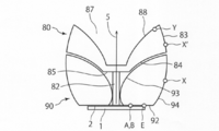
- FIG. 8 shows a bird's eye view when the optical element 80 and the basic optical element 90 of this wide light distribution lens are separated.
- the wide light distribution lens has a rotationally symmetric shape with respect to the central axis 5 shown in FIG.
- the basic optical element 90 includes a flat bottom surface 92 having a round shape, a top surface 93 having a shape recessed toward the center, and a side surface 94.
- the upper surface (total reflection surface) 93 of the basic optical element 90 is a concave surface.
- the bottom surface 92 is an incident surface on which light from the light emitting element 1 is incident.
- the side surface 94 becomes an emission surface.
- the side surface 94 has a convex shape with respect to the central axis 5 and a shape in which the cross-sectional area increases from the bottom surface 92 toward the top surface 93.
- a through hole 11 is provided in the central portion of the basic optical element 90 along the central axis.
- the through-hole 11 has a shape in which the cross-sectional area once decreases from the incident surface 92 toward the upper surface, and then the cross-sectional area increases.
- the optical element 80 includes a first portion 81a, a second portion 81b connected to the first portion 81a, and a joining column 82 connected to the central portion of the bottom surface 85 of the first portion 81a.
- the optical element 80 and the basic optical element 90 are bonded by the bonding column 82.
- the tip of the joining column 82 is a male screw
- the through hole 11 of the basic optical element 90 is a female screw.
- the length of the column of the joining column 82 is determined so that an air layer is formed between the optical element 80 and the basic optical element 90.
- the optical element 80 and the basic optical element 90 can be attached and detached by the joining column 82.
- the joining column 82 and the through hole 11 may be bonded and fixed by an adhesive instead of being screwed.
- the bottom surface 85 of the first portion 81 a of the optical element 80 is flat, and the side surface 84 is a connection surface connected to the total reflection surface 93 of the basic optical element 90.
- the side surface 84 of the first portion 81a and the side surface 83 of the second portion 81b are connected by a joint surface having the same size and shape, and this joint surface is larger than the bottom surface 85.
- the side surface 83 of the second portion 81b is a total reflection / refractive transmission surface that totally reflects or refracts and transmits light that has passed through the optical element 80.
- the upper surface 88 of the second portion 81b has a shape that is recessed toward the center. That is, the upper surface 88 of the second portion 81b is a concave surface.
- This upper surface 88 is also referred to as an inner surface.
- a hole 87 is provided along the central axis 5 in the center of the optical element 80.
- the air holes 87 have a shape in which the cross-sectional area decreases downward from the upper surface 88 but does not reach the bottom surface 85.
- the light emitting element 1 is a surface light source
- the light emitting surface 2 of the light emitting element 1 is rectangular
- the size thereof is 10 mm ⁇ 16 mm.
- the dimension and shape of the light emitting surface 2 are not limited to this. Assuming that the area of the light emitting surface 2 is C, the radius r A of a virtual circle having half the area of the light emitting surface 2 is It becomes. If the size of the light emitting surface 2 is 10 mm ⁇ 16 mm, r A is about 5.0 mm. Point A is a point on the light emitting surface 2 a distance from the center axis 5 is r A.
- the distance from the central axis 5 is r A and the points on the light emitting surface 2 are A and B. That is, point A and point B are the same here.
- the angle between the vector XB connecting the point X and the point B was theta X
- ⁇ X is ⁇ X > ⁇ C Meet.
- the optical element 80 will be described.
- the optical element 80 is provided with a connection surface 84 along the total reflection surface 93.
- the connection surface 84 is connected to the total reflection / refractive transmission surface 83.
- the connection surface 84 is also connected to the bottom surface 85. Since the connection surface 84 has a shape along the total reflection surface 93 of the basic optical element 90, the expression (8) is satisfied in the same manner as the total reflection surface 93.
- the bottom surface 85 is flat, and the connection pillar 82 is connected at the center thereof.
- the distance from the central axis 5 of the end point of the total reflection / refractive transmission surface 83 on the side close to the light emitting surface 2 of the light emitting element 1 is the end point farthest from the light emitting surface 2 of the exit surface 94 of the basic optical element 90. It is equal to the distance from the central axis 5.
- the optical element 80 is provided with the air holes 87.
- a point on the inner surface 88 of the hole 87 is defined as Y.
- a point on the point Y side with respect to the central axis 5 is defined as E.
- 10 to 13 are cross-sectional views including the central axis 5.
- light rays emitted from the light emitting surface 2 of the light emitting element 1 are added.
- a light ray 35 emitted from a region between point B and point E on the light emitting surface 2 of the light emitting element 1 and incident on the incident surface 92 is totally reflected by the exit surface 94. Further, the light passes through the total reflection surface 93, enters the connection surface 84, is refracted and transmitted from the inner surface 88 of the hole 87, and is emitted forward.
- a light beam 36 emitted from the point E on the light emitting surface 2 and incident on the incident surface 92 is transmitted through the total reflection surface 93 and incident on the connection surface 84. Thereafter, the light is totally reflected by the inner surface 88 of the hole 87. Further, the light is refracted and transmitted from the total reflection / refractive transmission surface 83 and is emitted to the intermediate side of the central axis 5.
- a light ray 37 emitted from a region between point B and point E on the light emitting surface 2 and incident on the incident surface 92 is transmitted through the total reflection surface 93 and incident on the connection surface 84. Thereafter, the light is totally reflected by the total reflection / refractive transmission surface 83. Further, the light is refracted and transmitted by the inner surface 88 of the hole 87 and is emitted from the intermediate side to the front side.
- the light rays emitted from the light emitting surface 2 of the light emitting element 1 are finally emitted to the front side, the intermediate side, and the rear side, respectively.
- the first embodiment it is possible to provide a wide light distribution lens and an illumination device that can be made compact while sufficiently securing a light distribution angle.
- FIG. 14 is a bird's-eye view of the lighting apparatus according to the third embodiment.
- the illumination device 9 according to the third embodiment includes a light emitting element 1 and a wide light distribution lens.
- This wide light distribution lens includes an optical element 80 and a basic optical element 90.
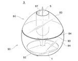
- FIG. 15 shows a bird's eye view when the optical element 80 and the basic optical element 90 of this wide light distribution lens are separated.
- the wide light distribution lens has a rotationally symmetric shape with respect to the central axis 5 shown in FIG.
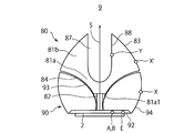
- FIG. 16 is a cross-sectional view of the illumination device 9 according to the third embodiment.
- the basic optical element 90 includes a bottom surface 92 having a concave shape, an upper surface 93 having a shape recessed toward the center, and a side surface 94.
- the upper surface (total reflection surface) 93 of the basic optical element 90 is a concave surface.
- the bottom surface 92 is an incident surface on which light from the light emitting element 1 is incident.
- the side surface 94 becomes an emission surface.
- the side surface 94 has a convex shape with respect to the central axis 5 and has a shape in which the cross-sectional area once increases as it goes from the bottom surface 92 to the upper surface 93 and thereafter the cross-sectional area decreases.
- a through hole 11 is provided in the central portion of the basic optical element 90 along the central axis.
- the through-hole 11 has a shape in which the cross-sectional area once decreases from the incident surface 92 toward the upper surface, and then the cross-sectional area increases.
- the optical element 80 includes a first portion 81a, a second portion 81b connected to the first portion 81a, and a joining column 82 connected to the central portion of the bottom surface 81a1 of the first portion 81a.
- the optical element 80 and the basic optical element 90 are bonded by the bonding column 82.
- the tip of the joining column 82 is a male screw
- the through hole 11 of the basic optical element 90 is a female screw.
- the length of the column of the joining column 82 is determined so that an air layer is formed between the optical element 80 and the basic optical element 90.
- the optical element 80 and the basic optical element 90 can be attached and detached by the joining column 82.
- the joining column 82 and the through hole 11 may be bonded and fixed by an adhesive instead of being screwed.
- the side surface 84 of the first portion 81 a of the optical element 80 serves as a connection surface connected to the total reflection surface 93 of the basic optical element 90. Further, the side surface 84 of the first portion 81a and the side surface 83 of the second portion 81b are connected by a joint surface having the same size and shape, and this joint surface is larger than the bottom surface.
- the side surface 83 of the second portion 81b serves as a total reflection / refractive transmission surface that totally reflects or refracts and transmits light emitted from the light emitting surface 2.
- the upper surface 88 of the second portion 81b is provided with a hole 87 that communicates with the joint surface of the second portion 81b along the central axis 5.
- a side surface 88 of the hole 87 is also referred to as an inner surface.
- the air holes 87 have substantially the same cross-sectional area from the top to the bottom, and have a cylindrical shape.
- the air hole 87 continues from the first portion 81a, and has a shape in which a cross-sectional area decreases as it goes downward in the first portion 81a.
- the light emitting element 1 is placed on the substrate 101.
- the substrate 101 and the light emitting element 1 are thermally connected.
- the light-emitting element 1 is a surface light source
- the light-emitting surface 2 of the light-emitting element 1 is rectangular, and its size is 10 mm ⁇ 16 mm.
- the dimension and shape of the light emitting surface 2 are not limited to this. Assuming that the area of the light emitting surface 2 is C, the radius r A of a virtual circle having half the area of the light emitting surface 2 is It becomes. If the size of the light emitting surface 2 is 10 mm ⁇ 16 mm, r A is about 5.0 mm. Point A is a point on the light emitting surface 2 a distance from the center axis 5 is r A. However, point A is not limited to this, anything good if that distance from the central axis 5 becomes less r A.
- the distance from the central axis 5 is r A and the points on the light emitting surface 2 are A and B. That is, point A and point B are the same here.
- the optical element 80 When taking a cross section in a plane including the central axis 5, the X point on the exit surface 94, and the inward normal vector at the point X, the angle between the vector XB connecting the point X and the point B was theta X When ⁇ X is ⁇ X > ⁇ C Meet.
- the optical element 80 is provided with a connection surface 84 along the total reflection surface 93.
- the connection surface 84 is connected to the total reflection / refractive transmission surface 83.
- the connection surface 84 is connected to the bottom surface 81a1, and the connection column 82 is connected to the center of the bottom surface 81a1. Since the connection surface 84 has a shape along the total reflection surface 93 of the basic optical element 90, the expression (8) is satisfied in the same manner as the total reflection surface 93.
- the bottom surface 81a1 is flat.
- the distance from the central axis 5 of the end point near the light emitting surface 2 of the total reflection / refractive transmission surface 83 is from the central axis 5 of the end point far from the light emitting surface 2 of the exit surface 94 of the basic optical element 90. Equal to distance.
- a cross section is taken on a plane including the central axis 5, an inward normal vector at the point X ′ and a vector X′B connecting the point X ′ and the point B at the point X ′ on the total reflection / refractive transmission surface 83.
- ⁇ X' the angle formed by the door ⁇ X is, ⁇ X > ⁇ C Meet.
- the optical element 80 is provided with the hole 87 as described above.
- a point on the inner surface 88 of the hole 87 is defined as Y.
- the inward normal vector at the point Y and the central axis 5 are orthogonal. That is, the inner surface 88 has a finite region parallel to the central axis 5. As the point on the inner surface 88 gets closer to the light emitting surface 2, the distance from the central axis 5 becomes smaller.
- 17 and 18 are cross-sectional views including the central axis 5. In these figures, light rays emitted from the light emitting surface 2 of the light emitting element 1 are added.
- a light ray 38 emitted from the region between the point B and the point E on the light emitting surface 2 and incident on the incident surface 92 is transmitted through the total reflection surface 93 of the basic optical element 90 and is connected to the connection surface 84 of the optical element 80. And is totally reflected by the total reflection / refractive transmission surface 83. Further, it passes through the inner surface 88 of the hole 87 and is finally emitted from the total reflection / refractive transmission surface 83 to the intermediate side.
- a light ray 39 emitted from the region between point B and point E on the light emitting surface 2 and incident on the incident surface 92 is totally reflected by the exit surface 94. Further, the light passes through the total reflection surface 93 of the basic optical element 90, enters the connection surface 84 of the optical element 80, is totally reflected by the inner surface 88 of the hole 87, and finally comes to the front side from the total reflection / refractive transmission surface 83. It is injected.
- the hole 87 appears to shine to the observer. That is, since the inside of the optical element 80 appears to shine, it can be made to resemble light emission that is closer to a point light source and closer to a point light source such as an incandescent lamp. That is, the retrofit feeling increases.
- the light emitted from the light emitting surface 2 of the light emitting element 1 is emitted backward, as in the case of FIG. 4 of the first embodiment. That is, the light emitted from the light emitting surface 2 of the light emitting element 1 and incident on the incident surface 92 and totally reflected by the total reflection / refractive transmission surface 93 of the basic optical element 90 is emitted backward.
- the light rays emitted from the light emitting surface 2 of the light emitting element 1 are finally emitted to the front side, the intermediate side, and the rear side, respectively. In this way, light rays are emitted in all directions, and wide light distribution can be realized.
- the incident surface 92 is provided with a recess.
- the inner surface 88 has a finite region parallel to the central axis 5 and shines along the central axis 5, the filament appears to shine, that is, the retrofit to the incandescent bulb is increased and the reverse tapered shape is not provided. Therefore, there is an advantage that it is easy to cut and can be easily extracted with a mold during manufacture.
- the third embodiment it is possible to provide a wide light distribution lens and a proof device that can be made compact while sufficiently ensuring a light distribution angle.
Landscapes
- Physics & Mathematics (AREA)
- Engineering & Computer Science (AREA)
- General Engineering & Computer Science (AREA)
- General Physics & Mathematics (AREA)
- Optics & Photonics (AREA)
- Non-Portable Lighting Devices Or Systems Thereof (AREA)
- Lenses (AREA)
- Securing Globes, Refractors, Reflectors Or The Like (AREA)
- Led Device Packages (AREA)
Abstract
Le problème à résoudre selon l'invention est la réalisation d'une lentille de distribution de lumière large et un dispositif d'éclairage qui peut être rendu compact tout en garantissant un angle de distribution de lumière suffisant. La solution selon l'invention consiste en un premier élément optique dont la forme est symétrique en rotation par rapport à l'axe central et qui est transparent par rapport à la lumière visible, le premier élément optique ayant une première partie et une seconde partie reliée à la première partie, la première partie ayant une surface inférieure dont la forme est évidée ou plate et une surface latérale reliée à la surface inférieure, la seconde partie ayant une surface supérieure et une surface latérale reliée à la surface supérieure, la surface latérale de la première partie et la surface latérale de la seconde partie étant reliées au niveau de surfaces de liaison de taille et de forme identiques, et les surfaces de liaison étant plus larges que la surface inférieure.
Priority Applications (3)
| Application Number | Priority Date | Filing Date | Title |
|---|---|---|---|
| JP2015530992A JP6089107B2 (ja) | 2013-08-09 | 2014-08-11 | 照明装置および広配光レンズ |
| PCT/JP2014/071233 WO2015020229A1 (fr) | 2013-08-09 | 2014-08-11 | Dispositif d'éclairage et lentille de répartition de lumière large |
| EP14833979.9A EP3037718B1 (fr) | 2013-08-09 | 2014-08-11 | Dispositif d'éclairage et lentille de répartition de lumière large |
Applications Claiming Priority (2)
| Application Number | Priority Date | Filing Date | Title |
|---|---|---|---|
| JP2013166928 | 2013-08-09 | ||
| JP2013-166928 | 2013-08-09 |
Publications (1)
| Publication Number | Publication Date |
|---|---|
| WO2015019683A1 true WO2015019683A1 (fr) | 2015-02-12 |
Family
ID=52461030
Family Applications (2)
| Application Number | Title | Priority Date | Filing Date |
|---|---|---|---|
| PCT/JP2014/063913 Ceased WO2015019683A1 (fr) | 2013-08-09 | 2014-05-27 | Dispositif d'éclairage et lentille de distribution de lumière large |
| PCT/JP2014/071233 Ceased WO2015020229A1 (fr) | 2013-08-09 | 2014-08-11 | Dispositif d'éclairage et lentille de répartition de lumière large |
Family Applications After (1)
| Application Number | Title | Priority Date | Filing Date |
|---|---|---|---|
| PCT/JP2014/071233 Ceased WO2015020229A1 (fr) | 2013-08-09 | 2014-08-11 | Dispositif d'éclairage et lentille de répartition de lumière large |
Country Status (3)
| Country | Link |
|---|---|
| EP (1) | EP3037718B1 (fr) |
| JP (1) | JP6089107B2 (fr) |
| WO (2) | WO2015019683A1 (fr) |
Cited By (2)
| Publication number | Priority date | Publication date | Assignee | Title |
|---|---|---|---|---|
| US10222050B2 (en) | 2015-02-05 | 2019-03-05 | Kabushiki Kaisha Toshiba | Lighting device |
| US10274185B2 (en) | 2014-03-28 | 2019-04-30 | Kabushiki Kaisha Toshiba | Lighting device |
Families Citing this family (4)
| Publication number | Priority date | Publication date | Assignee | Title |
|---|---|---|---|---|
| JP6675828B2 (ja) * | 2015-02-26 | 2020-04-08 | 三菱電機株式会社 | 照明用レンズ、発光装置及び照明器具 |
| KR101875026B1 (ko) * | 2017-04-21 | 2018-07-06 | 주식회사 에이치엘옵틱스 | 광 확산 렌즈 |
| JP7165629B2 (ja) | 2019-07-12 | 2022-11-04 | Dowaエレクトロニクス株式会社 | 発光素子ランプ及びその製造方法 |
| JP7458242B2 (ja) * | 2020-05-28 | 2024-03-29 | 株式会社小糸製作所 | 車両用灯具 |
Citations (3)
| Publication number | Priority date | Publication date | Assignee | Title |
|---|---|---|---|---|
| JP2011228204A (ja) * | 2010-04-22 | 2011-11-10 | Toki Corporation Kk | 発光装置 |
| JP2012160666A (ja) * | 2011-02-02 | 2012-08-23 | Sharp Corp | 光源モジュール及び照明装置 |
| JP2013084346A (ja) * | 2011-10-06 | 2013-05-09 | Hitachi Appliances Inc | 照明装置 |
Family Cites Families (6)
| Publication number | Priority date | Publication date | Assignee | Title |
|---|---|---|---|---|
| JP4754126B2 (ja) * | 2001-09-18 | 2011-08-24 | ライツ・アドバンスト・テクノロジー株式会社 | 導光部材および標識灯 |
| ITRE20060052A1 (it) * | 2006-04-28 | 2007-10-29 | Incerti Simonini Snc | DISPOSITIVO OTTICO SECONDARIO PER LAMPADE A LEDs |
| TWI524030B (zh) * | 2009-04-02 | 2016-03-01 | 皇家飛利浦電子股份有限公司 | 發光裝置及照明器具 |
| JP4660654B1 (ja) * | 2009-11-04 | 2011-03-30 | ナルックス株式会社 | 照明装置 |
| TWI418854B (zh) * | 2010-03-16 | 2013-12-11 | Cal Comp Electronics & Comm Co | 透鏡結構 |
| CN102829437B (zh) * | 2011-06-15 | 2015-04-01 | 光宝科技股份有限公司 | 光罩及具光罩的灯具 |
-
2014
- 2014-05-27 WO PCT/JP2014/063913 patent/WO2015019683A1/fr not_active Ceased
- 2014-08-11 EP EP14833979.9A patent/EP3037718B1/fr active Active
- 2014-08-11 JP JP2015530992A patent/JP6089107B2/ja active Active
- 2014-08-11 WO PCT/JP2014/071233 patent/WO2015020229A1/fr not_active Ceased
Patent Citations (3)
| Publication number | Priority date | Publication date | Assignee | Title |
|---|---|---|---|---|
| JP2011228204A (ja) * | 2010-04-22 | 2011-11-10 | Toki Corporation Kk | 発光装置 |
| JP2012160666A (ja) * | 2011-02-02 | 2012-08-23 | Sharp Corp | 光源モジュール及び照明装置 |
| JP2013084346A (ja) * | 2011-10-06 | 2013-05-09 | Hitachi Appliances Inc | 照明装置 |
Cited By (2)
| Publication number | Priority date | Publication date | Assignee | Title |
|---|---|---|---|---|
| US10274185B2 (en) | 2014-03-28 | 2019-04-30 | Kabushiki Kaisha Toshiba | Lighting device |
| US10222050B2 (en) | 2015-02-05 | 2019-03-05 | Kabushiki Kaisha Toshiba | Lighting device |
Also Published As
| Publication number | Publication date |
|---|---|
| EP3037718A4 (fr) | 2017-03-08 |
| EP3037718B1 (fr) | 2020-09-16 |
| JP6089107B2 (ja) | 2017-03-01 |
| EP3037718A1 (fr) | 2016-06-29 |
| JPWO2015020229A1 (ja) | 2017-03-02 |
| WO2015020229A1 (fr) | 2015-02-12 |
Similar Documents
| Publication | Publication Date | Title |
|---|---|---|
| EP2276076B1 (fr) | Unité luminescente dotée d une lentille | |
| JP6089107B2 (ja) | 照明装置および広配光レンズ | |
| US9442241B2 (en) | Optics for illumination devices | |
| US9465205B2 (en) | Optical lens and backlight module incorporating the same | |
| TWI626401B (zh) | 透鏡及其發光裝置 | |
| TWI534391B (zh) | 光源導引結構及發光裝置 | |
| US20130083541A1 (en) | Optical lens, light-emitting diode optical component and light-emitting diode illumination lamp | |
| JP6222557B2 (ja) | 車両用灯具 | |
| CN204083863U (zh) | 照明装置和光导 | |
| JP2014003168A (ja) | レンズ、照明装置、受光装置および光学装置 | |
| CN103975191A (zh) | 光束控制部件以及照明装置 | |
| CN105202394A (zh) | 透镜组合及应用透镜组合的照明装置 | |
| US8047675B1 (en) | Light emitting diode optical system and related methods | |
| TWI574049B (zh) | 透鏡及使用該透鏡的背光模組 | |
| WO2014174859A1 (fr) | Dispositif d'éclairage et lentille de répartition lumineuse large | |
| CN107614964A (zh) | 光束控制部件、发光装置及照明装置 | |
| CN105222086B (zh) | 二次光学元件及光源模块 | |
| JP2012209049A (ja) | Led照明装置およびレンズ | |
| US10125951B2 (en) | Light flux control member, light-emitting device and lighting device | |
| CN205037137U (zh) | 透镜组合及应用透镜组合的照明装置 | |
| CN205299098U (zh) | 透镜模组及led灯具 | |
| CN205037087U (zh) | 一种发光装置 | |
| US8616733B1 (en) | Light emitting diode optical system and related methods | |
| CN205807297U (zh) | 准直光学器件以及聚光灯 | |
| CN102411162A (zh) | 使光线均匀出射的导光柱及应用此导光柱的led灯 |
Legal Events
| Date | Code | Title | Description |
|---|---|---|---|
| 121 | Ep: the epo has been informed by wipo that ep was designated in this application |
Ref document number: 14833813 Country of ref document: EP Kind code of ref document: A1 |
|
| NENP | Non-entry into the national phase |
Ref country code: DE |
|
| 122 | Ep: pct application non-entry in european phase |
Ref document number: 14833813 Country of ref document: EP Kind code of ref document: A1 |