WO2015019698A1 - Fil-électrode fourré pour soudage supplémentaire et procédé de soudage - Google Patents
Fil-électrode fourré pour soudage supplémentaire et procédé de soudage Download PDFInfo
- Publication number
- WO2015019698A1 WO2015019698A1 PCT/JP2014/065251 JP2014065251W WO2015019698A1 WO 2015019698 A1 WO2015019698 A1 WO 2015019698A1 JP 2014065251 W JP2014065251 W JP 2014065251W WO 2015019698 A1 WO2015019698 A1 WO 2015019698A1
- Authority
- WO
- WIPO (PCT)
- Prior art keywords
- mass
- welding
- flux
- less
- wire
- Prior art date
- Legal status (The legal status is an assumption and is not a legal conclusion. Google has not performed a legal analysis and makes no representation as to the accuracy of the status listed.)
- Ceased
Links
Images
Classifications
-
- B—PERFORMING OPERATIONS; TRANSPORTING
- B23—MACHINE TOOLS; METAL-WORKING NOT OTHERWISE PROVIDED FOR
- B23K—SOLDERING OR UNSOLDERING; WELDING; CLADDING OR PLATING BY SOLDERING OR WELDING; CUTTING BY APPLYING HEAT LOCALLY, e.g. FLAME CUTTING; WORKING BY LASER BEAM
- B23K35/00—Rods, electrodes, materials, or media, for use in soldering, welding, or cutting
- B23K35/22—Rods, electrodes, materials, or media, for use in soldering, welding, or cutting characterised by the composition or nature of the material
- B23K35/36—Selection of non-metallic compositions, e.g. coatings or fluxes; Selection of soldering or welding materials, conjoint with selection of non-metallic compositions, both selections being of interest
- B23K35/368—Selection of non-metallic compositions of core materials either alone or conjoint with selection of soldering or welding materials
-
- B—PERFORMING OPERATIONS; TRANSPORTING
- B23—MACHINE TOOLS; METAL-WORKING NOT OTHERWISE PROVIDED FOR
- B23K—SOLDERING OR UNSOLDERING; WELDING; CLADDING OR PLATING BY SOLDERING OR WELDING; CUTTING BY APPLYING HEAT LOCALLY, e.g. FLAME CUTTING; WORKING BY LASER BEAM
- B23K35/00—Rods, electrodes, materials, or media, for use in soldering, welding, or cutting
- B23K35/02—Rods, electrodes, materials, or media, for use in soldering, welding, or cutting characterised by mechanical features, e.g. shape
- B23K35/0255—Rods, electrodes, materials, or media, for use in soldering, welding, or cutting characterised by mechanical features, e.g. shape for use in welding
- B23K35/0261—Rods, electrodes or wires
- B23K35/0266—Rods, electrodes or wires flux-cored
-
- B—PERFORMING OPERATIONS; TRANSPORTING
- B23—MACHINE TOOLS; METAL-WORKING NOT OTHERWISE PROVIDED FOR
- B23K—SOLDERING OR UNSOLDERING; WELDING; CLADDING OR PLATING BY SOLDERING OR WELDING; CUTTING BY APPLYING HEAT LOCALLY, e.g. FLAME CUTTING; WORKING BY LASER BEAM
- B23K35/00—Rods, electrodes, materials, or media, for use in soldering, welding, or cutting
- B23K35/22—Rods, electrodes, materials, or media, for use in soldering, welding, or cutting characterised by the composition or nature of the material
- B23K35/24—Selection of soldering or welding materials proper
- B23K35/30—Selection of soldering or welding materials proper with the principal constituent melting at less than 1550°C
- B23K35/3053—Fe as the principal constituent
- B23K35/3073—Fe as the principal constituent with Mn as next major constituent
-
- B—PERFORMING OPERATIONS; TRANSPORTING
- B23—MACHINE TOOLS; METAL-WORKING NOT OTHERWISE PROVIDED FOR
- B23K—SOLDERING OR UNSOLDERING; WELDING; CLADDING OR PLATING BY SOLDERING OR WELDING; CUTTING BY APPLYING HEAT LOCALLY, e.g. FLAME CUTTING; WORKING BY LASER BEAM
- B23K35/00—Rods, electrodes, materials, or media, for use in soldering, welding, or cutting
- B23K35/40—Making wire or rods for soldering or welding
- B23K35/406—Filled tubular wire or rods
-
- C—CHEMISTRY; METALLURGY
- C21—METALLURGY OF IRON
- C21D—MODIFYING THE PHYSICAL STRUCTURE OF FERROUS METALS; GENERAL DEVICES FOR HEAT TREATMENT OF FERROUS OR NON-FERROUS METALS OR ALLOYS; MAKING METAL MALLEABLE, e.g. BY DECARBURISATION OR TEMPERING
- C21D9/00—Heat treatment, e.g. annealing, hardening, quenching or tempering, adapted for particular articles; Furnaces therefor
- C21D9/46—Heat treatment, e.g. annealing, hardening, quenching or tempering, adapted for particular articles; Furnaces therefor for sheet metals
-
- C—CHEMISTRY; METALLURGY
- C21—METALLURGY OF IRON
- C21D—MODIFYING THE PHYSICAL STRUCTURE OF FERROUS METALS; GENERAL DEVICES FOR HEAT TREATMENT OF FERROUS OR NON-FERROUS METALS OR ALLOYS; MAKING METAL MALLEABLE, e.g. BY DECARBURISATION OR TEMPERING
- C21D9/00—Heat treatment, e.g. annealing, hardening, quenching or tempering, adapted for particular articles; Furnaces therefor
- C21D9/52—Heat treatment, e.g. annealing, hardening, quenching or tempering, adapted for particular articles; Furnaces therefor for wires; for strips ; for rods of unlimited length
- C21D9/525—Heat treatment, e.g. annealing, hardening, quenching or tempering, adapted for particular articles; Furnaces therefor for wires; for strips ; for rods of unlimited length for wire, for rods
-
- C—CHEMISTRY; METALLURGY
- C22—METALLURGY; FERROUS OR NON-FERROUS ALLOYS; TREATMENT OF ALLOYS OR NON-FERROUS METALS
- C22C—ALLOYS
- C22C38/00—Ferrous alloys, e.g. steel alloys
- C22C38/02—Ferrous alloys, e.g. steel alloys containing silicon
-
- C—CHEMISTRY; METALLURGY
- C22—METALLURGY; FERROUS OR NON-FERROUS ALLOYS; TREATMENT OF ALLOYS OR NON-FERROUS METALS
- C22C—ALLOYS
- C22C38/00—Ferrous alloys, e.g. steel alloys
- C22C38/04—Ferrous alloys, e.g. steel alloys containing manganese
-
- C—CHEMISTRY; METALLURGY
- C22—METALLURGY; FERROUS OR NON-FERROUS ALLOYS; TREATMENT OF ALLOYS OR NON-FERROUS METALS
- C22C—ALLOYS
- C22C38/00—Ferrous alloys, e.g. steel alloys
- C22C38/06—Ferrous alloys, e.g. steel alloys containing aluminium
-
- C—CHEMISTRY; METALLURGY
- C22—METALLURGY; FERROUS OR NON-FERROUS ALLOYS; TREATMENT OF ALLOYS OR NON-FERROUS METALS
- C22C—ALLOYS
- C22C38/00—Ferrous alloys, e.g. steel alloys
- C22C38/18—Ferrous alloys, e.g. steel alloys containing chromium
- C22C38/40—Ferrous alloys, e.g. steel alloys containing chromium with nickel
- C22C38/58—Ferrous alloys, e.g. steel alloys containing chromium with nickel with more than 1.5% by weight of manganese
Definitions
- the present invention relates to a flux-cored wire for additional welding used for additional welding to the weld metal toe of main welding and a welding method. More specifically, the present invention relates to a flux-cored wire for additional welding having a structure in which a steel outer shell is filled with flux and a welding method for performing additional welding using this wire.
- additional beads may be formed at the weld toe of the main weld for the purpose of improving the fatigue strength of welded joints or reducing residual stress (see Patent Documents 1 to 3).
- a welding material used for welding additional welding
- a material having a composition similar to that of main welding is generally used.
- Patent Document 1 discloses that a weld metal having a Ni content of 4 to 12% by mass and a Cr content of 7 to 15% by mass is formed by additional welding.
- Patent Document 2 the content of C, Cr, Ni, Si, Mn, Mo, and Nb is specified for the weld metal formed by additional welding, and the amount of Ni and Cr is increased. Therefore, the martensite transformation start temperature is set to 120 to 400 ° C. Further, Patent Document 3 contains C: 0.20 mass% or less, Cr: 5.0-18.0 mass%, Ni: 3.0-15.0 mass% for additional welding, and the balance A welding material having a composition consisting of Fe and inevitable impurities has been proposed.
- the main object of the present invention is to provide a flux-cored wire and a welding method capable of improving the fatigue strength of the welded portion while maintaining good crack resistance of the weld metal in addition welding. .
- the present inventor has conducted extensive experiments to solve the above-described problems.
- the welding material with an increased Mn content can reduce the added amount of Cr and Ni, and in addition welding, it can achieve improved fatigue strength of the weld while ensuring the crack resistance and toughness of the weld metal.
- the headline, the present invention has been reached.
- the flux-cored wire for additional welding is a flux-cored wire in which a steel outer sheath is filled with flux, and Si: 0.2 to 1.0 mass%, Mn: 3.0 to 10.0% by mass, C: 0.1% by mass or less, P: 0.03% by mass or less, S: 0.03% by mass or less, Cr and / or Ni: 3 in total It has a composition restricted to .8% by mass or less, and is used for additional welding to the weld metal toe portion of main welding.
- the flux-cored wire of the present invention may have Ni: 0.5 to 3.8% by mass and Mn: 3 to 7% by mass based on the total mass of the wire.
- the flux-cored wire of the present invention may further contain Al: 0.1 to 0.5% by mass with respect to the total mass of the wire.
- the welding method according to the present invention uses the above-described flux-cored wire for additional welding, and contains at least Mn: 0.5 to 2.0 mass%, Ni: 3.5 mass% or less (excluding 0). Additional welding is performed on the weld metal toe of the main weld made of steel.
- the additional welding in the welding method of the present invention can be performed, for example, by gas shielded arc welding using a shielding gas containing 10% by volume or more of CO 2 .
- the fatigue strength of the welded portion is maintained while maintaining good crack resistance of the weld metal in addition welding without adding a large amount of Ni or Cr. Can be improved.
- the flux-cored wire of this embodiment is a steel outer shell filled with flux, and Si is 0.2 to 1.0 mass% and Mn is 3.0 to 10.0 mass% with respect to the total mass of the wire. contains. At the same time, C is controlled to 0.1 mass% or less, P is 0.03 mass% or less, S is 0.03 mass% or less, and Cr and / or Ni are regulated to 3.8 mass% or less in total. Moreover, in addition to each component mentioned above, specific amount of Al can also be added to the flux cored wire of this embodiment.
- the outer diameter of the flux-cored wire of the present embodiment is not particularly limited, but is, for example, 0.9 to 1.6 mm.
- the flux filling rate can be set to any value as long as each component in the wire is within the above-mentioned range, but from the viewpoint of wire drawability and workability (feedability, etc.) during welding. Therefore, the content is preferably 8 to 25% by mass based on the total mass of the wire.
- Si 0.2 to 1.0% by mass
- Si has the effect of increasing the strength of the weld metal and reducing the stress concentration by smoothing the toe shape of the bead.
- Si content is less than 0.2% by mass, these effects are insufficient.
- Si content exceeds 1.0% by mass, grain boundary segregation occurs and high temperature cracking is likely to occur. Therefore, the Si content is 0.2 to 1.0% by mass with respect to the total mass of the wire.
- Si source in the flux-cored wire of the present embodiment include Si contained in the steel outer sheath, Fe—Si, Fe—Si—Mn, Fe—Si—Mg, REM— contained in the flux.
- Si contained in the steel outer sheath
- examples thereof include Ca—Si, Fe—Si—B, SiO 2 , ZrSiO 3 , K 2 SiF 6, and MgSiO 3 .
- Mn has the effect of enhancing the hardenability, lowering the martensitic transformation start temperature (Ms point) of the weld metal, and applying compressive residual stress to the weld metal toe.
- Mn has an effect of suppressing hot cracking by fixing an appropriate amount of S, which affects hot cracking resistance of the weld metal, as MnS.
- Mn content is less than 3% by mass, these effects are insufficient, and when the Mn content exceeds 10% by mass, the weld metal is excessively cured, and hot cracking is likely to occur. Toughness also decreases. Therefore, the Mn content is 3 to 10% by mass with respect to the total mass of the wire.
- Mn source in the flux-cored wire of the present embodiment include Mn contained in the steel outer sheath, Fe—Mn, Si—Mn, MnO 2 contained in the flux, and the like.
- C 0.1% by mass or less
- C has the effect of improving the strength of the weld metal and increasing the hardenability and lowering the Ms point of the weld metal, but is also an element that easily induces hot cracking. Specifically, when the C content exceeds 0.1% by mass, hot cracking is likely to occur in the weld metal. Therefore, the C content is regulated to 0.1% by mass or less per the total mass of the wire.
- P 0.03 mass% or less
- P is also an element that easily induces hot cracking.
- the P content exceeds 0.03% by mass, hot cracking is likely to occur in the weld metal. Therefore, the P content is regulated to 0.03% by mass or less per the total mass of the wire.
- S 0.03 mass% or less
- S is also an element that easily induces hot cracking as with P described above.
- S content exceeds 0.03% by mass, hot cracking is likely to occur in the weld metal. Therefore, the S content is also regulated to 0.03% by mass or less per total mass of the wire.
- Cr and Ni 3.8% by mass or less in total
- Cr has the effect of lowering the Ms point of the weld metal and improving the fatigue strength of the weld.
- an iron alloy containing Cr forms a harder weld metal
- the weld metal It hardens excessively and causes a decrease in crack resistance and toughness.
- Ni also has the effect of lowering the Ms point of the weld metal, and by adding an appropriate amount, the fatigue strength of the welded portion can be further improved, but when added in a large amount, the crack resistance of the weld metal and Toughness decreases.
- the total content of Cr and Ni exceeds 3.8% by mass with respect to the total mass of the wire, the crack resistance and toughness of the weld metal are lowered, and the desired characteristics cannot be obtained. Therefore, in the flux-cored wire of the present embodiment, when Cr and / or Ni is added, the total content is made 3.8% by mass or less.
- Cr and Ni may contain both of them within the above-described range, but may contain either one or both.
- the Ni content is preferably 0.5 to 3.8% by mass and the Mn content is preferably 3 to 7% by mass.
- the relationship between the Mn content and the Ni content satisfies the following formula 2.
- [Mn] in the following formula 2 is the amount of Mn (mass%) per the total mass of the wire
- [Ni] is the amount of Ni (mass%) per the total mass of the wire.
- the sum of the Mn content and the 1 ⁇ 2 amount of the Ni content is within the range of more than 3 and less than 6, while sufficiently ensuring the toughness of the weld metal, A weld metal having excellent hot cracking resistance can be obtained even in current and high-speed welding.
- Al 0.1 to 0.5% by mass
- Al has the effect of making the slag generated on the bead surface uniform, but it slightly increases the Ms point of the weld metal, so it is added as necessary in the flux-cored wire of this embodiment.
- the Al content is less than 0.1% by mass, the above-described addition effect cannot be obtained, and if the Al content exceeds 0.5% by mass, the toughness of the weld metal deteriorates, This causes a reduction in fatigue strength of the weld due to an increase in Ms point. Therefore, when Al is added, the content is 0.1 to 0.5% by mass with respect to the total mass of the wire. Thereby, uniform slag can be formed over the entire surface of the weld bead.
- the remainder in the component composition of the flux-cored wire of this embodiment is Fe and inevitable impurities.
- Examples of inevitable impurities in the flux-cored wire of this embodiment include Nb and V.
- O and N are also contained in the remainder of the flux cored wire of this embodiment.
- Mo, Ti, Zr, Mg, K, Ca, Na, and F may be added to the flux-cored wire of the present embodiment in addition to the components described above.
- the flux cored wire of this embodiment is used for additional welding to the weld metal toe of main welding.
- the weld metal composition of the main weld portion is not particularly limited, but the flux-cored wire of the present embodiment has a weld metal of the main weld portion of Mn: 0.5 to 2.0 mass%, This is particularly suitable when the steel contains at least Ni: 3.5% by mass or less (excluding 0).
- Mn content and the Ni content are in this range, it is possible to suppress a reduction in the effect due to dilution of the base material and to form a welded joint having excellent crack resistance and fatigue strength.
- the fatigue strength may be insufficient.
- the Mn content of the weld metal in the main weld exceeds 2.0% by mass, the crack resistance may be lowered.
- the weld metal of the main weld part exceeds 3.5 mass% and contains Ni, the crack resistance of a weld metal may fall, and also manufacturing cost will increase.
- the conditions for additional welding are not particularly limited, gas shield arc welding is usually used.
- the shielding gas preferably contains a CO 2 or 10 vol%, it is more preferable to use 100% CO 2 gas. The occurrence of poor fusion can be suppressed by using a shielding gas containing CO 2 .
- the flux-cored wire of the present embodiment has an increased amount of Mn as compared with the conventional case. Therefore, even if the content of Ni or Cr is reduced, the crack resistance of the weld metal in addition welding is reduced. The fatigue strength of the welded portion can be improved while maintaining good.
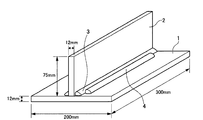
- FIG. 1 is a perspective view showing a double-sided fillet weld joint used for evaluation.
- flux was filled in the outer skin made of steel having the composition shown in Table 1 below, and flux-cored wires of Examples and Comparative Examples were produced.
- the diameter of the wire was 1.2 mm, and the flux filling rate was in the range of 12 to 18% by mass with respect to the total mass of the wire.
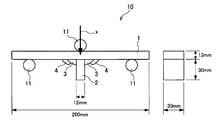
- FIG. 2 is a side view showing a fatigue test method.
- the fatigue strength was evaluated by cutting out the test piece 10 shown in FIG. 2 from the both-side fillet welded joint shown in FIG. 1 and conducting a partial piece swing three-point bending fatigue test.
- a 200 kN fatigue tester (PA24901) manufactured by Takes Group Co., Ltd. was used, and the test conditions were environmental temperature: room temperature, distance between fulcrums 11: 150 mm, load control with sine wave, frequency: 15 Hz, stress Ratio: 0.1 (partial swing).
- the arrow x shown in FIG. 2 shows a load application direction.
- the number of repetitions was 500,000 times, and the time strength was measured as fatigue strength.
- the fatigue strength of 300 MPa or more was evaluated as ⁇ (excellent), 250 MPa or more and less than 300 MPa as ⁇ (good), and less than 250 MPa as x (impossible).
- ⁇ Crack resistance> The crack resistance of the weld metal was evaluated based on the results of a C-type constrained cracking test based on JIS Z3155. At that time, the welding current was 280 A, and the welding speed was 40, 50, 70 cm / min. Then, after welding, an X-ray transmission test was performed, and x (impossible) the case where cracks occurred even at 40 cm / min, ⁇ (possible) those where no cracks occurred only at 40 cm / min, and 50 cm / min or less. Evaluations were made with ⁇ (good) indicating no cracking at the speed and ⁇ (excellent) indicating no cracking even at 70 cm / min.
- ⁇ Toughness> The toughness of all weld metals was evaluated based on the results of impact performance tests of all weld metals at 0 ° C. based on JIS Z3111.
- the impact performance at 0 ° C. was 60 J or more, and ⁇ (excellent), and 47 J or more and less than 60 J was rated ⁇ (good).
- the mechanical performance of a welded joint part is normally ensured by the main welded part, the additional welded part is not required to perform as well as the main welded part. Therefore, in this example, even if the impact performance at 0 ° C. is less than 47 J, it can be practically applied if it is 10 J or more.
- the impact performance at 0 ° C. is less than 10 J, the weld metal is excessively cured, and cracking may occur during press correction, and therefore, ⁇ (impossible).
- the remainder in the wire composition of additional welding shown in the following Table 3 and Table 4 is Fe and inevitable impurities.
- Cr and Ni are often present as unavoidable impurities in the steel shell.
- the comparative example No. In No. 39 Cr was 0.07% by mass. 21 and 22 contain 0.03% by mass of Ni, but these are added as impurities and are not positively added.
- the Cr content and the Ni content of the additional welding wires shown in Tables 3 and 4 include those added as inevitable impurities.
- No. 34 was inferior in fatigue strength of the weld.
- No. 35 was inferior in crack resistance of the weld metal.
- Example No. using the flux-cored wire produced within the scope of the present invention For Nos. 1 to 29, good results were obtained in all evaluations of slag tension, fatigue strength of welds, toughness of weld metal, and crack resistance.
Landscapes
- Chemical & Material Sciences (AREA)
- Engineering & Computer Science (AREA)
- Mechanical Engineering (AREA)
- Materials Engineering (AREA)
- Metallurgy (AREA)
- Organic Chemistry (AREA)
- Physics & Mathematics (AREA)
- Thermal Sciences (AREA)
- Crystallography & Structural Chemistry (AREA)
- Nonmetallic Welding Materials (AREA)
- Plasma & Fusion (AREA)
- Arc Welding In General (AREA)
Abstract
Priority Applications (3)
| Application Number | Priority Date | Filing Date | Title |
|---|---|---|---|
| EP14834592.9A EP3031568A4 (fr) | 2013-08-07 | 2014-06-09 | Fil-électrode fourré pour soudage supplémentaire et procédé de soudage |
| CN201480042456.2A CN105408053B (zh) | 2013-08-07 | 2014-06-09 | 附加焊接用药芯焊丝和焊接方法 |
| KR1020167003205A KR101823798B1 (ko) | 2013-08-07 | 2014-06-09 | 부가 용접용 플럭스 코어드 와이어 및 용접 방법 |
Applications Claiming Priority (2)
| Application Number | Priority Date | Filing Date | Title |
|---|---|---|---|
| JP2013-164606 | 2013-08-07 | ||
| JP2013164606A JP6061809B2 (ja) | 2013-08-07 | 2013-08-07 | 付加溶接用フラックス入りワイヤ及び溶接方法 |
Publications (1)
| Publication Number | Publication Date |
|---|---|
| WO2015019698A1 true WO2015019698A1 (fr) | 2015-02-12 |
Family
ID=52461042
Family Applications (1)
| Application Number | Title | Priority Date | Filing Date |
|---|---|---|---|
| PCT/JP2014/065251 Ceased WO2015019698A1 (fr) | 2013-08-07 | 2014-06-09 | Fil-électrode fourré pour soudage supplémentaire et procédé de soudage |
Country Status (5)
| Country | Link |
|---|---|
| EP (1) | EP3031568A4 (fr) |
| JP (1) | JP6061809B2 (fr) |
| KR (1) | KR101823798B1 (fr) |
| CN (1) | CN105408053B (fr) |
| WO (1) | WO2015019698A1 (fr) |
Families Citing this family (6)
| Publication number | Priority date | Publication date | Assignee | Title |
|---|---|---|---|---|
| JP6740805B2 (ja) * | 2016-08-23 | 2020-08-19 | 国立大学法人大阪大学 | 溶接方法、溶接継手の製造方法および溶接継手 |
| US11529697B2 (en) | 2017-09-29 | 2022-12-20 | Lincoln Global, Inc. | Additive manufacturing using aluminum-containing wire |
| US11426824B2 (en) | 2017-09-29 | 2022-08-30 | Lincoln Global, Inc. | Aluminum-containing welding electrode |
| JP7606071B2 (ja) * | 2020-10-07 | 2024-12-25 | 日本製鉄株式会社 | 溶接継手の製造方法及び開先充填用のフラックス入りカットワイヤ |
| CN115106673B (zh) * | 2021-03-22 | 2023-11-14 | 宝山钢铁股份有限公司 | 高强管线钢单面焊双面成型焊接性评估方法 |
| CN115609175B (zh) * | 2021-07-13 | 2026-03-17 | 宝山钢铁股份有限公司 | 焊接接头疲劳行为评价方法 |
Citations (9)
| Publication number | Priority date | Publication date | Assignee | Title |
|---|---|---|---|---|
| JP2003251489A (ja) | 2002-02-27 | 2003-09-09 | Jfe Steel Kk | 低合金鉄鋼材料の溶接継手及びその溶接方法 |
| JP2003275890A (ja) | 2002-03-18 | 2003-09-30 | Nippon Steel Corp | 疲労寿命向上処理方法およびそれによる長寿命溶接継手 |
| JP2004042133A (ja) | 2002-05-15 | 2004-02-12 | Jfe Steel Kk | 耐応力腐食割れ性に優れた溶接継手およびその製造方法 |
| JP2012115877A (ja) * | 2010-12-01 | 2012-06-21 | Kobe Steel Ltd | フラックス入りワイヤ |
| JP2013018012A (ja) * | 2011-07-08 | 2013-01-31 | Nippon Steel & Sumitomo Metal Corp | 高張力鋼ガスシールドアーク溶接用フラックス入りワイヤ |
| JP2013091082A (ja) * | 2011-10-26 | 2013-05-16 | Nippon Steel & Sumikin Welding Co Ltd | 低温用鋼のサブマージアーク溶接方法 |
| JP2013173179A (ja) * | 2012-02-27 | 2013-09-05 | Kobe Steel Ltd | 耐水素脆化感受性に優れた溶接金属 |
| JP2013226577A (ja) * | 2012-04-25 | 2013-11-07 | Nippon Steel & Sumikin Welding Co Ltd | 原油油槽鋼のガスシールドアーク溶接用フラックス入りワイヤ |
| JP2014018852A (ja) * | 2012-07-23 | 2014-02-03 | Kobe Steel Ltd | サブマージアーク溶接用フラックス入りワイヤ |
Family Cites Families (6)
| Publication number | Priority date | Publication date | Assignee | Title |
|---|---|---|---|---|
| US5233149A (en) * | 1991-08-02 | 1993-08-03 | Eaton Corporation | Reprocessing weld and method |
| US6336583B1 (en) * | 1999-03-23 | 2002-01-08 | Exxonmobil Upstream Research Company | Welding process and welded joints |
| JP5179073B2 (ja) * | 2007-03-08 | 2013-04-10 | 日鐵住金溶接工業株式会社 | ガスシールドアーク溶接用フラックス入りワイヤ |
| EP2289661B1 (fr) * | 2009-08-27 | 2014-04-02 | Nippon Steel & Sumikin Welding Co., Ltd. | Fil à flux incorporé pour soudure à l'arc protégée en acier de grande résistance |
| JP5459083B2 (ja) * | 2010-06-04 | 2014-04-02 | 新日鐵住金株式会社 | 高張力鋼用炭酸ガスシールドアーク溶接用フラックス入りワイヤ |
| JP5557790B2 (ja) * | 2011-04-13 | 2014-07-23 | 日鐵住金溶接工業株式会社 | 2電極水平すみ肉co2ガスシールドアーク溶接用フラックス入りワイヤ |
-
2013
- 2013-08-07 JP JP2013164606A patent/JP6061809B2/ja not_active Expired - Fee Related
-
2014
- 2014-06-09 WO PCT/JP2014/065251 patent/WO2015019698A1/fr not_active Ceased
- 2014-06-09 EP EP14834592.9A patent/EP3031568A4/fr not_active Withdrawn
- 2014-06-09 CN CN201480042456.2A patent/CN105408053B/zh not_active Expired - Fee Related
- 2014-06-09 KR KR1020167003205A patent/KR101823798B1/ko not_active Expired - Fee Related
Patent Citations (9)
| Publication number | Priority date | Publication date | Assignee | Title |
|---|---|---|---|---|
| JP2003251489A (ja) | 2002-02-27 | 2003-09-09 | Jfe Steel Kk | 低合金鉄鋼材料の溶接継手及びその溶接方法 |
| JP2003275890A (ja) | 2002-03-18 | 2003-09-30 | Nippon Steel Corp | 疲労寿命向上処理方法およびそれによる長寿命溶接継手 |
| JP2004042133A (ja) | 2002-05-15 | 2004-02-12 | Jfe Steel Kk | 耐応力腐食割れ性に優れた溶接継手およびその製造方法 |
| JP2012115877A (ja) * | 2010-12-01 | 2012-06-21 | Kobe Steel Ltd | フラックス入りワイヤ |
| JP2013018012A (ja) * | 2011-07-08 | 2013-01-31 | Nippon Steel & Sumitomo Metal Corp | 高張力鋼ガスシールドアーク溶接用フラックス入りワイヤ |
| JP2013091082A (ja) * | 2011-10-26 | 2013-05-16 | Nippon Steel & Sumikin Welding Co Ltd | 低温用鋼のサブマージアーク溶接方法 |
| JP2013173179A (ja) * | 2012-02-27 | 2013-09-05 | Kobe Steel Ltd | 耐水素脆化感受性に優れた溶接金属 |
| JP2013226577A (ja) * | 2012-04-25 | 2013-11-07 | Nippon Steel & Sumikin Welding Co Ltd | 原油油槽鋼のガスシールドアーク溶接用フラックス入りワイヤ |
| JP2014018852A (ja) * | 2012-07-23 | 2014-02-03 | Kobe Steel Ltd | サブマージアーク溶接用フラックス入りワイヤ |
Non-Patent Citations (1)
| Title |
|---|
| See also references of EP3031568A4 * |
Also Published As
| Publication number | Publication date |
|---|---|
| KR101823798B1 (ko) | 2018-01-30 |
| EP3031568A4 (fr) | 2017-01-18 |
| JP6061809B2 (ja) | 2017-01-18 |
| CN105408053A (zh) | 2016-03-16 |
| CN105408053B (zh) | 2018-08-10 |
| KR20160028473A (ko) | 2016-03-11 |
| JP2015033703A (ja) | 2015-02-19 |
| EP3031568A1 (fr) | 2016-06-15 |
Similar Documents
| Publication | Publication Date | Title |
|---|---|---|
| KR101827193B1 (ko) | 저수소계 피복 아크 용접봉 | |
| JP5005309B2 (ja) | 高張力鋼用ガスシールドアーク溶接フラックス入りワイヤ | |
| JP6040125B2 (ja) | フラックス入りワイヤ | |
| JP6322093B2 (ja) | ガスシールドアーク溶接用フラックス入りワイヤ | |
| JP6061809B2 (ja) | 付加溶接用フラックス入りワイヤ及び溶接方法 | |
| JP2013018012A (ja) | 高張力鋼ガスシールドアーク溶接用フラックス入りワイヤ | |
| JP2011020154A (ja) | ガスシールド溶接用フラックス入りワイヤ | |
| JP6155810B2 (ja) | ガスシールドアーク溶接用高Niフラックス入りワイヤ | |
| KR101962050B1 (ko) | 가스 실드 아크 용접용 플럭스 코어드 와이어 | |
| JP6914182B2 (ja) | 被覆アーク溶接棒 | |
| JP6017406B2 (ja) | セルフシールドアーク溶接用ステンレス鋼フラックス入りワイヤ | |
| JP4209913B2 (ja) | ガスシールドアーク溶接用フラックス入りワイヤ | |
| JP6829111B2 (ja) | Tig溶接用溶加材 | |
| JP2009034724A (ja) | 高強度鋼用のサブマージアーク溶接用フラックス入りワイヤ。 | |
| JP4722811B2 (ja) | 高強度鋼用のサブマージアーク溶接用フラックス入りワイヤ。 | |
| JP6504894B2 (ja) | 被覆アーク溶接棒 | |
| JP2011206828A (ja) | 細径多電極サブマージアーク溶接用フラックス入り溶接ワイヤ | |
| KR100581027B1 (ko) | 마르텐사이트계 스테인레스강 용접용 플럭스 충전 와이어 | |
| JP2008248377A (ja) | 疲労特性に優れた溶接継手および溶接方法 | |
| JP2016151052A (ja) | 耐sr特性に優れた高強度uoe鋼管のサブマージアーク溶接金属 | |
| JP5151421B2 (ja) | フラックス入りワイヤ及びそれを用いた溶接継手 | |
| JP2019171457A (ja) | 高速溶接用フラックス入りワイヤ及び高速アーク溶接方法 |
Legal Events
| Date | Code | Title | Description |
|---|---|---|---|
| WWE | Wipo information: entry into national phase |
Ref document number: 201480042456.2 Country of ref document: CN |
|
| 121 | Ep: the epo has been informed by wipo that ep was designated in this application |
Ref document number: 14834592 Country of ref document: EP Kind code of ref document: A1 |
|
| WWE | Wipo information: entry into national phase |
Ref document number: 2014834592 Country of ref document: EP |
|
| ENP | Entry into the national phase |
Ref document number: 20167003205 Country of ref document: KR Kind code of ref document: A |
|
| NENP | Non-entry into the national phase |
Ref country code: DE |