WO2015019804A1 - Système de régénération de volant d'inertie, et son procédé de commande - Google Patents
Système de régénération de volant d'inertie, et son procédé de commande Download PDFInfo
- Publication number
- WO2015019804A1 WO2015019804A1 PCT/JP2014/068794 JP2014068794W WO2015019804A1 WO 2015019804 A1 WO2015019804 A1 WO 2015019804A1 JP 2014068794 W JP2014068794 W JP 2014068794W WO 2015019804 A1 WO2015019804 A1 WO 2015019804A1
- Authority
- WO
- WIPO (PCT)
- Prior art keywords
- flywheel
- clutch
- kinetic energy
- transmission
- regeneration system
- Prior art date
- Legal status (The legal status is an assumption and is not a legal conclusion. Google has not performed a legal analysis and makes no representation as to the accuracy of the status listed.)
- Ceased
Links
Images
Classifications
-
- B—PERFORMING OPERATIONS; TRANSPORTING
- B60—VEHICLES IN GENERAL
- B60K—ARRANGEMENT OR MOUNTING OF PROPULSION UNITS OR OF TRANSMISSIONS IN VEHICLES; ARRANGEMENT OR MOUNTING OF PLURAL DIVERSE PRIME-MOVERS IN VEHICLES; AUXILIARY DRIVES FOR VEHICLES; INSTRUMENTATION OR DASHBOARDS FOR VEHICLES; ARRANGEMENTS IN CONNECTION WITH COOLING, AIR INTAKE, GAS EXHAUST OR FUEL SUPPLY OF PROPULSION UNITS IN VEHICLES
- B60K6/00—Arrangement or mounting of plural diverse prime-movers for mutual or common propulsion, e.g. hybrid propulsion systems comprising electric motors and internal combustion engines
- B60K6/08—Prime-movers comprising combustion engines and mechanical or fluid energy storing means
- B60K6/10—Prime-movers comprising combustion engines and mechanical or fluid energy storing means by means of a chargeable mechanical accumulator, e.g. flywheel
-
- B—PERFORMING OPERATIONS; TRANSPORTING
- B60—VEHICLES IN GENERAL
- B60K—ARRANGEMENT OR MOUNTING OF PROPULSION UNITS OR OF TRANSMISSIONS IN VEHICLES; ARRANGEMENT OR MOUNTING OF PLURAL DIVERSE PRIME-MOVERS IN VEHICLES; AUXILIARY DRIVES FOR VEHICLES; INSTRUMENTATION OR DASHBOARDS FOR VEHICLES; ARRANGEMENTS IN CONNECTION WITH COOLING, AIR INTAKE, GAS EXHAUST OR FUEL SUPPLY OF PROPULSION UNITS IN VEHICLES
- B60K6/00—Arrangement or mounting of plural diverse prime-movers for mutual or common propulsion, e.g. hybrid propulsion systems comprising electric motors and internal combustion engines
- B60K6/08—Prime-movers comprising combustion engines and mechanical or fluid energy storing means
- B60K6/10—Prime-movers comprising combustion engines and mechanical or fluid energy storing means by means of a chargeable mechanical accumulator, e.g. flywheel
- B60K6/105—Prime-movers comprising combustion engines and mechanical or fluid energy storing means by means of a chargeable mechanical accumulator, e.g. flywheel the accumulator being a flywheel
-
- B—PERFORMING OPERATIONS; TRANSPORTING
- B60—VEHICLES IN GENERAL
- B60W—CONJOINT CONTROL OF VEHICLE SUB-UNITS OF DIFFERENT TYPE OR DIFFERENT FUNCTION; CONTROL SYSTEMS SPECIALLY ADAPTED FOR HYBRID VEHICLES; ROAD VEHICLE DRIVE CONTROL SYSTEMS FOR PURPOSES NOT RELATED TO THE CONTROL OF A PARTICULAR SUB-UNIT
- B60W10/00—Conjoint control of vehicle sub-units of different type or different function
- B60W10/02—Conjoint control of vehicle sub-units of different type or different function including control of driveline clutches
-
- B—PERFORMING OPERATIONS; TRANSPORTING
- B60—VEHICLES IN GENERAL
- B60W—CONJOINT CONTROL OF VEHICLE SUB-UNITS OF DIFFERENT TYPE OR DIFFERENT FUNCTION; CONTROL SYSTEMS SPECIALLY ADAPTED FOR HYBRID VEHICLES; ROAD VEHICLE DRIVE CONTROL SYSTEMS FOR PURPOSES NOT RELATED TO THE CONTROL OF A PARTICULAR SUB-UNIT
- B60W10/00—Conjoint control of vehicle sub-units of different type or different function
- B60W10/24—Conjoint control of vehicle sub-units of different type or different function including control of energy storage means
-
- B—PERFORMING OPERATIONS; TRANSPORTING
- B60—VEHICLES IN GENERAL
- B60W—CONJOINT CONTROL OF VEHICLE SUB-UNITS OF DIFFERENT TYPE OR DIFFERENT FUNCTION; CONTROL SYSTEMS SPECIALLY ADAPTED FOR HYBRID VEHICLES; ROAD VEHICLE DRIVE CONTROL SYSTEMS FOR PURPOSES NOT RELATED TO THE CONTROL OF A PARTICULAR SUB-UNIT
- B60W30/00—Purposes of road vehicle drive control systems not related to the control of a particular sub-unit, e.g. of systems using conjoint control of vehicle sub-units
- B60W30/18—Propelling the vehicle
- B60W30/18009—Propelling the vehicle related to particular drive situations
- B60W30/18027—Drive off, accelerating from standstill
-
- B—PERFORMING OPERATIONS; TRANSPORTING
- B60—VEHICLES IN GENERAL
- B60W—CONJOINT CONTROL OF VEHICLE SUB-UNITS OF DIFFERENT TYPE OR DIFFERENT FUNCTION; CONTROL SYSTEMS SPECIALLY ADAPTED FOR HYBRID VEHICLES; ROAD VEHICLE DRIVE CONTROL SYSTEMS FOR PURPOSES NOT RELATED TO THE CONTROL OF A PARTICULAR SUB-UNIT
- B60W30/00—Purposes of road vehicle drive control systems not related to the control of a particular sub-unit, e.g. of systems using conjoint control of vehicle sub-units
- B60W30/18—Propelling the vehicle
- B60W30/18009—Propelling the vehicle related to particular drive situations
- B60W30/18109—Braking
- B60W30/18127—Regenerative braking
-
- F—MECHANICAL ENGINEERING; LIGHTING; HEATING; WEAPONS; BLASTING
- F16—ENGINEERING ELEMENTS AND UNITS; GENERAL MEASURES FOR PRODUCING AND MAINTAINING EFFECTIVE FUNCTIONING OF MACHINES OR INSTALLATIONS; THERMAL INSULATION IN GENERAL
- F16D—COUPLINGS FOR TRANSMITTING ROTATION; CLUTCHES; BRAKES
- F16D48/00—External control of clutches
- F16D48/06—Control by electric or electronic means, e.g. of fluid pressure
- F16D48/062—Control by electric or electronic means, e.g. of fluid pressure of a clutch system with a plurality of fluid actuated clutches
-
- F—MECHANICAL ENGINEERING; LIGHTING; HEATING; WEAPONS; BLASTING
- F16—ENGINEERING ELEMENTS AND UNITS; GENERAL MEASURES FOR PRODUCING AND MAINTAINING EFFECTIVE FUNCTIONING OF MACHINES OR INSTALLATIONS; THERMAL INSULATION IN GENERAL
- F16D—COUPLINGS FOR TRANSMITTING ROTATION; CLUTCHES; BRAKES
- F16D48/00—External control of clutches
- F16D48/06—Control by electric or electronic means, e.g. of fluid pressure
- F16D48/08—Regulating clutch take-up on starting
-
- B—PERFORMING OPERATIONS; TRANSPORTING
- B60—VEHICLES IN GENERAL
- B60W—CONJOINT CONTROL OF VEHICLE SUB-UNITS OF DIFFERENT TYPE OR DIFFERENT FUNCTION; CONTROL SYSTEMS SPECIALLY ADAPTED FOR HYBRID VEHICLES; ROAD VEHICLE DRIVE CONTROL SYSTEMS FOR PURPOSES NOT RELATED TO THE CONTROL OF A PARTICULAR SUB-UNIT
- B60W2510/00—Input parameters relating to a particular sub-units
- B60W2510/10—Change speed gearings
- B60W2510/1005—Transmission ratio engaged
-
- B—PERFORMING OPERATIONS; TRANSPORTING
- B60—VEHICLES IN GENERAL
- B60W—CONJOINT CONTROL OF VEHICLE SUB-UNITS OF DIFFERENT TYPE OR DIFFERENT FUNCTION; CONTROL SYSTEMS SPECIALLY ADAPTED FOR HYBRID VEHICLES; ROAD VEHICLE DRIVE CONTROL SYSTEMS FOR PURPOSES NOT RELATED TO THE CONTROL OF A PARTICULAR SUB-UNIT
- B60W2510/00—Input parameters relating to a particular sub-units
- B60W2510/10—Change speed gearings
- B60W2510/1015—Input shaft speed, e.g. turbine speed
-
- B—PERFORMING OPERATIONS; TRANSPORTING
- B60—VEHICLES IN GENERAL
- B60W—CONJOINT CONTROL OF VEHICLE SUB-UNITS OF DIFFERENT TYPE OR DIFFERENT FUNCTION; CONTROL SYSTEMS SPECIALLY ADAPTED FOR HYBRID VEHICLES; ROAD VEHICLE DRIVE CONTROL SYSTEMS FOR PURPOSES NOT RELATED TO THE CONTROL OF A PARTICULAR SUB-UNIT
- B60W2510/00—Input parameters relating to a particular sub-units
- B60W2510/24—Energy storage means
-
- B—PERFORMING OPERATIONS; TRANSPORTING
- B60—VEHICLES IN GENERAL
- B60W—CONJOINT CONTROL OF VEHICLE SUB-UNITS OF DIFFERENT TYPE OR DIFFERENT FUNCTION; CONTROL SYSTEMS SPECIALLY ADAPTED FOR HYBRID VEHICLES; ROAD VEHICLE DRIVE CONTROL SYSTEMS FOR PURPOSES NOT RELATED TO THE CONTROL OF A PARTICULAR SUB-UNIT
- B60W2540/00—Input parameters relating to occupants
- B60W2540/10—Accelerator pedal position
-
- B—PERFORMING OPERATIONS; TRANSPORTING
- B60—VEHICLES IN GENERAL
- B60W—CONJOINT CONTROL OF VEHICLE SUB-UNITS OF DIFFERENT TYPE OR DIFFERENT FUNCTION; CONTROL SYSTEMS SPECIALLY ADAPTED FOR HYBRID VEHICLES; ROAD VEHICLE DRIVE CONTROL SYSTEMS FOR PURPOSES NOT RELATED TO THE CONTROL OF A PARTICULAR SUB-UNIT
- B60W2552/00—Input parameters relating to infrastructure
- B60W2552/15—Road slope, i.e. the inclination of a road segment in the longitudinal direction
-
- B—PERFORMING OPERATIONS; TRANSPORTING
- B60—VEHICLES IN GENERAL
- B60W—CONJOINT CONTROL OF VEHICLE SUB-UNITS OF DIFFERENT TYPE OR DIFFERENT FUNCTION; CONTROL SYSTEMS SPECIALLY ADAPTED FOR HYBRID VEHICLES; ROAD VEHICLE DRIVE CONTROL SYSTEMS FOR PURPOSES NOT RELATED TO THE CONTROL OF A PARTICULAR SUB-UNIT
- B60W2710/00—Output or target parameters relating to a particular sub-units
- B60W2710/02—Clutches
- B60W2710/025—Clutch slip, i.e. difference between input and output speeds
-
- B—PERFORMING OPERATIONS; TRANSPORTING
- B60—VEHICLES IN GENERAL
- B60W—CONJOINT CONTROL OF VEHICLE SUB-UNITS OF DIFFERENT TYPE OR DIFFERENT FUNCTION; CONTROL SYSTEMS SPECIALLY ADAPTED FOR HYBRID VEHICLES; ROAD VEHICLE DRIVE CONTROL SYSTEMS FOR PURPOSES NOT RELATED TO THE CONTROL OF A PARTICULAR SUB-UNIT
- B60W2710/00—Output or target parameters relating to a particular sub-units
- B60W2710/02—Clutches
- B60W2710/027—Clutch torque
-
- B—PERFORMING OPERATIONS; TRANSPORTING
- B60—VEHICLES IN GENERAL
- B60W—CONJOINT CONTROL OF VEHICLE SUB-UNITS OF DIFFERENT TYPE OR DIFFERENT FUNCTION; CONTROL SYSTEMS SPECIALLY ADAPTED FOR HYBRID VEHICLES; ROAD VEHICLE DRIVE CONTROL SYSTEMS FOR PURPOSES NOT RELATED TO THE CONTROL OF A PARTICULAR SUB-UNIT
- B60W2710/00—Output or target parameters relating to a particular sub-units
- B60W2710/10—Change speed gearings
- B60W2710/1005—Transmission ratio engaged
-
- F—MECHANICAL ENGINEERING; LIGHTING; HEATING; WEAPONS; BLASTING
- F16—ENGINEERING ELEMENTS AND UNITS; GENERAL MEASURES FOR PRODUCING AND MAINTAINING EFFECTIVE FUNCTIONING OF MACHINES OR INSTALLATIONS; THERMAL INSULATION IN GENERAL
- F16D—COUPLINGS FOR TRANSMITTING ROTATION; CLUTCHES; BRAKES
- F16D2500/00—External control of clutches by electric or electronic means
- F16D2500/10—System to be controlled
- F16D2500/102—Actuator
- F16D2500/1026—Hydraulic
-
- F—MECHANICAL ENGINEERING; LIGHTING; HEATING; WEAPONS; BLASTING
- F16—ENGINEERING ELEMENTS AND UNITS; GENERAL MEASURES FOR PRODUCING AND MAINTAINING EFFECTIVE FUNCTIONING OF MACHINES OR INSTALLATIONS; THERMAL INSULATION IN GENERAL
- F16D—COUPLINGS FOR TRANSMITTING ROTATION; CLUTCHES; BRAKES
- F16D2500/00—External control of clutches by electric or electronic means
- F16D2500/10—System to be controlled
- F16D2500/108—Gear
- F16D2500/1088—CVT
-
- F—MECHANICAL ENGINEERING; LIGHTING; HEATING; WEAPONS; BLASTING
- F16—ENGINEERING ELEMENTS AND UNITS; GENERAL MEASURES FOR PRODUCING AND MAINTAINING EFFECTIVE FUNCTIONING OF MACHINES OR INSTALLATIONS; THERMAL INSULATION IN GENERAL
- F16D—COUPLINGS FOR TRANSMITTING ROTATION; CLUTCHES; BRAKES
- F16D2500/00—External control of clutches by electric or electronic means
- F16D2500/30—Signal inputs
- F16D2500/31—Signal inputs from the vehicle
- F16D2500/3108—Vehicle speed
-
- F—MECHANICAL ENGINEERING; LIGHTING; HEATING; WEAPONS; BLASTING
- F16—ENGINEERING ELEMENTS AND UNITS; GENERAL MEASURES FOR PRODUCING AND MAINTAINING EFFECTIVE FUNCTIONING OF MACHINES OR INSTALLATIONS; THERMAL INSULATION IN GENERAL
- F16D—COUPLINGS FOR TRANSMITTING ROTATION; CLUTCHES; BRAKES
- F16D2500/00—External control of clutches by electric or electronic means
- F16D2500/70—Details about the implementation of the control system
- F16D2500/704—Output parameters from the control unit; Target parameters to be controlled
- F16D2500/70402—Actuator parameters
- F16D2500/7041—Position
-
- Y—GENERAL TAGGING OF NEW TECHNOLOGICAL DEVELOPMENTS; GENERAL TAGGING OF CROSS-SECTIONAL TECHNOLOGIES SPANNING OVER SEVERAL SECTIONS OF THE IPC; TECHNICAL SUBJECTS COVERED BY FORMER USPC CROSS-REFERENCE ART COLLECTIONS [XRACs] AND DIGESTS
- Y02—TECHNOLOGIES OR APPLICATIONS FOR MITIGATION OR ADAPTATION AGAINST CLIMATE CHANGE
- Y02T—CLIMATE CHANGE MITIGATION TECHNOLOGIES RELATED TO TRANSPORTATION
- Y02T10/00—Road transport of goods or passengers
- Y02T10/10—Internal combustion engine [ICE] based vehicles
- Y02T10/40—Engine management systems
-
- Y—GENERAL TAGGING OF NEW TECHNOLOGICAL DEVELOPMENTS; GENERAL TAGGING OF CROSS-SECTIONAL TECHNOLOGIES SPANNING OVER SEVERAL SECTIONS OF THE IPC; TECHNICAL SUBJECTS COVERED BY FORMER USPC CROSS-REFERENCE ART COLLECTIONS [XRACs] AND DIGESTS
- Y02—TECHNOLOGIES OR APPLICATIONS FOR MITIGATION OR ADAPTATION AGAINST CLIMATE CHANGE
- Y02T—CLIMATE CHANGE MITIGATION TECHNOLOGIES RELATED TO TRANSPORTATION
- Y02T10/00—Road transport of goods or passengers
- Y02T10/60—Other road transportation technologies with climate change mitigation effect
- Y02T10/62—Hybrid vehicles
Definitions
- the present invention relates to a flywheel regeneration system and a control method thereof.
- JP2012-516417A has a flywheel that can be connected / disconnected by a flywheel clutch on the input shaft of the transmission, and when the vehicle decelerates, the flywheel clutch is engaged and the flywheel is rotated by the rotation input from the drive wheels,
- a flywheel regenerative system for converting vehicle kinetic energy into flywheel kinetic energy is disclosed.
- flywheel regeneration system if the flywheel clutch is released, the regenerated kinetic energy can be stored in the flywheel, and if the flywheel clutch is engaged during start-up or acceleration, it is stored in the flywheel.
- the released kinetic energy can be released and used for starting and accelerating the vehicle.
- the flywheel regeneration system described above when the vehicle is started using the kinetic energy stored in the flywheel, if the flywheel clutch is engaged without considering the stored kinetic energy, the driver Unintended startability may occur. For example, when creeping is performed in a state where the kinetic energy stored in the flywheel is large, if the flywheel clutch is engaged, the driving force generated by the drive wheels increases, and the vehicle may start or accelerate suddenly.
- This invention solves such a problem, and when starting using the kinetic energy preserve
- a flywheel regeneration system includes a transmission provided between a drive source and a drive wheel, a flywheel that can be engaged with an input shaft side of the transmission, a flywheel, and a transmission. And a flywheel clutch that connects and disconnects the power transmission between the flywheel and the transmission. When the vehicle decelerates, the flywheel clutch is engaged, and the flywheel is rotated by the kinetic energy during deceleration.
- a flywheel regeneration system that performs regeneration and includes a start control unit that controls the engagement state of the flywheel clutch based on the kinetic energy stored in the flywheel when the vehicle starts.
- a control method for a flywheel regeneration system includes a transmission provided between a drive source and a drive wheel, a flywheel that can be engaged with an input shaft of the transmission, and a flywheel. Between the flywheel and the transmission, and a flywheel clutch that connects and disconnects the power transmission between the flywheel and the transmission. The flywheel clutch is engaged when the vehicle decelerates, and the flywheel is driven by the kinetic energy during deceleration.
- the engagement state of the flywheel clutch is controlled based on the kinetic energy of the flywheel when starting the vehicle, it is possible to suppress the startability unintended by the driver when starting the vehicle.
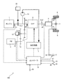
- FIG. 1 is a schematic configuration diagram of a vehicle in the present embodiment.
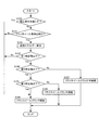
- FIG. 2 is a flowchart for explaining the vehicle start control according to this embodiment.
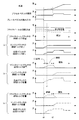
- FIG. 3 is a time chart showing changes in the engagement torque capacity of the flywheel clutch when the vehicle starts.
- FIG. 1 shows an overall configuration of a vehicle 100 provided with a flywheel regeneration system according to an embodiment of the present invention.
- the vehicle 100 decelerates the output rotation of the engine 1 as a power source, a flywheel 2 for regeneration, a continuously variable transmission (hereinafter referred to as CVT) 3 that continuously changes the output rotation of the engine 1, and the CVT 3.
- CVT continuously variable transmission
- a final reduction gear 4, a differential 5, left and right drive wheels 6, a hydraulic circuit 7, and a controller 8 are provided.
- the engine clutch CL1 is provided between the engine 1 and the input shaft 3in of the CVT 3.
- the engine clutch CL1 is a clutch that is engaged and released by operating the electric actuator 30, and electrically controls the engagement torque capacity.
- a hydraulic clutch capable of controlling the fastening torque capacity by the supplied hydraulic pressure may be used.
- a start clutch CL2 is provided between the CVT 3 and the final speed reducer 4 to transmit the rotation from the engine 1 or the flywheel 2 input through the CVT 3 to the final speed reducer 4 when starting.
- the starting clutch CL2 is a hydraulic clutch capable of controlling the fastening torque capacity by the supplied hydraulic pressure.
- the oil pump 10 is connected to the input shaft 3in of the CVT 3 via a belt, gear, etc. (not shown).
- the oil pump 10 is a gear pump type or vane pump type oil pump that generates hydraulic pressure when the input shaft 3in of the CVT 3 rotates.
- the hydraulic pressure generated by the oil pump 10 is sent to the hydraulic circuit 7 and supplied from the hydraulic circuit 7 to the pulley of the CVT 3 and the start clutch CL2.
- flywheel 2 can be engaged with the input shaft 3 in of the CVT 3 via a pair of reduction gear trains 11 and 12 and a flywheel clutch CLfw.
- the flywheel 2 is a metal cylinder or disk, and is housed in a container that is vacuumed or decompressed to reduce windage loss during rotation.
- a flywheel clutch CLfw is provided between the reduction gear train 11 and the reduction gear train 12.
- the flywheel clutch CLfw is an electric clutch that can be switched between an engaged state (engaged, semi-engaged, and released) by the clutch actuator 13, and connects and disconnects power transmission between the flywheel 2 and the input shaft 3in of the CVT 3.
- An electric oil pump may be provided instead of the clutch actuator 13, and the flywheel clutch CLfw may be a hydraulic clutch capable of controlling the fastening torque capacity by the hydraulic pressure generated by the electric oil pump.
- the engagement state of the flywheel clutch CLfw is changed by controlling the engagement torque capacity.
- the hydraulic circuit 7 is configured by a solenoid valve or the like that operates in response to a signal from a controller 8 described later, and is connected to the CVT 3, the engine clutch CL1, the start clutch CL2, and the oil pump 10 through an oil passage.
- the hydraulic circuit 7 generates the hydraulic pressure required by the pulley of the CVT 3 and the start clutch CL2 using the hydraulic pressure generated by the oil pump 10 as the original pressure, and the generated hydraulic pressure is supplied to the pulley of the CVT 3, the engine clutch CL1, and the start clutch CL2. Supply.
- the brake 14 is an electronically controlled brake in which the brake pedal 15 and the master cylinder 16 are mechanically independent.
- the brake actuator 17 displaces the piston of the master cylinder 16, and hydraulic pressure corresponding to the required deceleration (deceleration requested by the driver, the same applies hereinafter) is supplied to the brake 14. Power is generated.
- the brake 14 is also provided on the driven wheel.
- the controller 8 includes a CPU, a RAM, an input / output interface, and the like.
- the controller 8 includes a rotation speed sensor 21 that detects the rotation speed of the engine 1, and a rotation speed sensor 22 that detects the rotation speed Nin of the input shaft 3in of the CVT 3.
- a rotational speed sensor 23 for detecting the rotational speed Nfw of the flywheel 2 a vehicle speed sensor 24 for detecting the vehicle speed VSP, an accelerator opening sensor 26 for detecting the opening APO of the accelerator pedal 25, and the depression amount of the brake pedal 15 by the driver Signals from the brake sensor 27, the gradient sensor 28, etc. are detected.
- the controller 8 performs various calculations based on the input signal, and controls the shift of the CVT 3, the clutch CL 1, CL 2, CLfw engagement state, and the brake actuator 17. In particular, when the driver depresses the brake pedal 15 and the vehicle 100 decelerates, the controller 8 fastens the flywheel clutch CLfw, rotates the flywheel 2 by the rotation input from the drive wheels 6, and the vehicle 100 The kinetic energy of the vehicle 100 is regenerated by converting the kinetic energy it has into the kinetic energy of the flywheel 2.
- the controller 8 controls the engagement torque capacity of the flywheel clutch CLfw so that a braking force (regenerative braking) corresponding to the required deceleration is obtained.
- the controller 8 operates the brake actuator 17 to increase the braking force of the brake 14 to reduce the request. Let speed be realized.
- the regenerated kinetic energy can be stored in the flywheel 2 by releasing the flywheel clutch CLfw. If the flywheel clutch CLfw is engaged in a state where kinetic energy is stored in the flywheel 2, the kinetic energy stored in the flywheel 2 can be used for starting and acceleration of the vehicle 100.
- flywheel start starting the vehicle 100 using the kinetic energy stored in the flywheel 2 is referred to as flywheel start.
- the flywheel 2 itself cannot control the kinetic energy to be released, when the flywheel starts, the flywheel 2 is driven from the flywheel 2 by controlling the fastening torque capacity of the flywheel clutch CLfw.
- the torque transmitted to the wheel 6 is controlled, and a desired driving force is generated by the driving wheel 6.
- step S100 the controller 8 determines whether or not a flywheel start prohibition condition is satisfied.
- the controller 8 is, for example, (a) when the select lever is operated from the N range, (b) when the road surface gradient is equal to or greater than a predetermined gradient, or (c) when the turn signal switch is operated. Or (d) When the hazard switch is operated, it is determined that the flywheel start prohibition condition is satisfied.
- the predetermined gradient is a gradient (uphill gradient) that may cause the vehicle 100 to slide down or the drive wheels 6 to slip when the flywheel starts.
- the flywheel 2 releases kinetic energy
- the flywheel 2 itself cannot control the released kinetic energy.
- a large driving force is required.
- the flywheel clutch CLfw The resolution is insufficient and cannot be controlled accurately. Therefore, if the flywheel starts on a road surface with a large gradient, the vehicle 100 may slide down, and the drive wheel 6 may slip when the road surface resistance is low, which is particularly noticeable in a front-wheel drive vehicle. . Therefore, when the road surface has a predetermined slope or more, flywheel start is prohibited. If the flywheel start prohibition condition is satisfied, the process proceeds to step S106. If the flywheel start prohibition condition is not satisfied, the process proceeds to step S101.
- step S101 the controller 8 determines whether or not to start flywheel. Specifically, the controller 8 determines whether or not the creep travel without the depression of the brake pedal 15 and the depression of the accelerator pedal 25 is requested, and when the creep travel is requested, the flywheel starts. If it is determined that the creep travel is not requested, it is determined that the flywheel is not started. If the flywheel start is performed, the process proceeds to step S102, and if the flywheel start is not performed, the process proceeds to step S106.
- step S102 the controller 8 calculates the kinetic energy of the flywheel 2 based on the signal from the rotational speed sensor 23.
- step S103 the controller 8 determines whether or not the calculated kinetic energy is equal to or less than a first predetermined value.
- the first predetermined value is a value that suppresses the deterioration of the flywheel clutch CLfw and the start clutch CL2 and suppresses the sudden start of the vehicle 100 when creep running is requested.
- the flywheel clutch CLfw or the start clutch CL2 When the kinetic energy of the flywheel 2 is large, that is, when the rotational speed Nfw of the flywheel 2 is high, the flywheel clutch CLfw or the start clutch CL2 is semi-engaged (or fastened) to release the kinetic energy from the flywheel 2. The amount of heat generated by the flywheel clutch CLfw or the start clutch CL2 increases, and the durability of the flywheel clutch CLfw or the start clutch CL2 may be reduced.
- the engagement torque capacity of the flywheel clutch CLfw must be controlled so that torque suitable for creep running is transmitted.
- the kinetic energy of the flywheel 2 is large, it is necessary to control so that the torque is transmitted slightly by reducing the fastening torque capacity.
- the resolution is insufficient in a region where the engagement torque capacity of the flywheel clutch CLfw is small, the engagement torque capacity of the flywheel clutch CLfw cannot be controlled to a value suitable for creep travel in such a case.
- the power transmission in the clutch CLfw is larger than a desired value, a large driving force is generated in the vehicle 100 and the vehicle 100 may start suddenly.
- the first predetermined value is set so as not to start the flywheel in such a case. If the calculated kinetic energy is less than or equal to the first predetermined value, the process proceeds to step S104. If the calculated kinetic energy is greater than the first predetermined value, the process proceeds to step S106.
- step S104 the controller 8 determines whether or not the calculated kinetic energy is equal to or less than a second predetermined value.
- the second predetermined value is a value that enables creep travel even if the flywheel clutch CLfw is not half-engaged and is engaged.
- the process proceeds to step S105, and when the calculated kinetic energy is greater than the second predetermined value, the process proceeds to step S107.
- step S105 the controller 8 determines whether or not the calculated kinetic energy is greater than a third predetermined value.
- the third predetermined value is a value set based on the oil amount balance limit.
- the CVT 3 and the starting clutch CL2 are operated by hydraulic pressure, and a predetermined hydraulic pressure is required to operate the CVT 3 and the starting clutch CL2 normally.
- the oil amount balance limit is a hydraulic pressure necessary for normal operation of the CVT 3, the starting clutch CL2, and the like.
- the discharge pressure of the oil pump 10 is also small, which may be below the oil amount balance limit.
- the third predetermined value is set so that the discharge pressure of the oil pump 10 does not fall below the oil amount balance limit when the flywheel starts. If the calculated kinetic energy is less than or equal to the third predetermined value, the process proceeds to step S106, and if the calculated kinetic energy is greater than the third predetermined value, the process proceeds to step S108.
- step S106 the controller 8 starts the engine 1 with the flywheel clutch CLfw released, engages the engine clutch CL1 and the start clutch CL2, and starts the vehicle 100.
- the controller 8 does not start the flywheel, the kinetic energy of the flywheel 2 is greater than the first predetermined value, or the kinetic energy of the flywheel 2 is equal to or less than the third predetermined value. In this case, the kinetic energy is not released from the flywheel 2, and the engine 1 is started to start the vehicle 100.
- step S107 the controller 8 semi-engages the flywheel clutch CLfw, engages the start clutch CL2, and starts the vehicle 100 using the flywheel 2.
- the controller 8 controls the engagement torque capacity of the flywheel clutch CLfw so as to perform creep running. Specifically, first, a target driving force determined from the vehicle speed VSP and the opening APO of the accelerator pedal 25 is calculated, and the target slip of the flywheel clutch CLfw is calculated from the target driving force and the current rotational speed and gradient of the flywheel 2. The amount is calculated, the engagement torque capacity of the flywheel clutch CLfw is determined, and feedback control is performed. In addition, when making it slip only with one clutch, the emitted-heat amount becomes large.
- the starting clutch CL2 similarly calculates the engagement torque capacity from the clutch input side rotational speed, the output side rotational speed (vehicle speed VSP), and the opening degree APO of the accelerator pedal 25, and aims
- the hydraulic pressure is supplied from the hydraulic circuit 7 so that the fastening torque capacity is as follows.
- step S108 the controller 8 fastens the flywheel clutch CLfw, fastens the start clutch CL2, and starts the vehicle 100 using the kinetic energy of the flywheel 2.
- the controller 8 engages the flywheel clutch CLfw to start the vehicle 100, and then the engine 1 Is started, the engine clutch CL1 is engaged, and the vehicle 100 is started by the driving force from the engine 1.
- the engagement control of the flywheel clutch CLfw increases the engagement torque capacity by a predetermined increase amount determined based on the oil temperature and the rotational speed of the flywheel 2 after the piston stroke. Complete fastening is performed and the fastening control is terminated.
- the starting clutch CL2 is set to a semi-engaged state to control the vehicle speed VSP.
- the rotational speed of the flywheel 2 and the respective fastening torque capacities when the kinetic energy of the flywheel 2 is equal to or lower than the second predetermined value and larger than the third predetermined value are indicated by alternate long and short dash lines ((c) in FIG. 3). ).
- the brake pedal 15 is not depressed and the vehicle 100 starts.
- the accelerator pedal 25 is not depressed, and the vehicle 100 performs creep running.
- the engagement torque capacity of the flywheel clutch CLfw is maintained at zero at time t0 as shown in FIG. CLfw is released. Further, the engine 1 is started at time t0, the engagement torque capacity of the engine clutch CL1 is increased, the oil pump 10 is driven to generate hydraulic pressure, and the start clutch CL2 is engaged, so that the creep travel by the engine 1 is performed. Do. Thereafter, at time t2, when the accelerator pedal 25 is stepped on and an acceleration request is made, the creep travel is terminated.
- the flywheel clutch CLfw is set to the vehicle speed VSP at time t0 as shown in FIG.
- the fastening torque capacity is appropriately controlled by the fastening torque capacity calculated from the rotational speed of the flywheel 2 and the opening degree APO of the accelerator pedal 25 to make a semi-fastened state, and the creep running by the flywheel 2 is performed.
- the engagement torque capacity is calculated from the clutch input side rotational speed, the output side rotational speed (vehicle speed VSP), and the opening degree APO of the accelerator pedal 25. It controls so that it may be in a half-fastened state with the fastened torque capacity. Note that the engagement torque capacity of the engine clutch CL1 is maintained at zero, and the engine clutch CL1 is released.
- flywheel clutch CLfw When the flywheel clutch CLfw is semi-engaged and the vehicle 100 is started, the kinetic energy of the flywheel 2 gradually decreases, and when the kinetic energy of the flywheel 2 falls below the second predetermined value at time t1, the flywheel clutch CLfw The fastening torque capacity is increased in order to completely fasten. Thereafter, at time t2, when the accelerator pedal 25 is stepped on and an acceleration request is made, the creep travel is terminated. Accordingly, flywheel clutch CLfw is released, engine clutch CL1 is engaged, and engine 1 is started to accelerate vehicle 100.
- the fastening torque capacity is increased by a predetermined amount determined based on the temperature and the rotational speed of the flywheel 2 to engage the flywheel clutch CLfw, and creep travel is performed by the flywheel 2.
- the starting clutch CL2 is set in a semi-engaged state so as to prevent an unintended acceleration feeling, and the vehicle speed VSP is controlled. Note that the engagement torque capacity of the engine clutch CL1 is maintained at zero, and the engine clutch CL1 is released.
- flywheel clutch CLfw When starting, if the kinetic energy of the flywheel 2 is greater than the first predetermined value, the flywheel clutch CLfw is released. Thereby, it can suppress that a big torque is transmitted from the flywheel 2 to the driving wheel 6, and it can suppress that the vehicle 100 starts suddenly. Moreover, it can suppress that calorific value of flywheel clutch CLfw etc. becomes large, and can suppress that durability, such as flywheel clutch CLfw, falls.
- the flywheel clutch CLfw When starting, if the kinetic energy of the flywheel 2 is below the first predetermined value, the flywheel clutch CLfw is semi-engaged. As a result, a desired driving force can be generated in the vehicle 100 to achieve acceleration intended by the driver, and creep running can be performed using the kinetic energy of the flywheel 2.
- the flywheel clutch CLfw When starting, if the kinetic energy of the flywheel 2 is less than or equal to the second predetermined value, the flywheel clutch CLfw is engaged. Accordingly, power loss in the flywheel clutch CLfw can be reduced, acceleration intended by the driver can be realized, and creep running can be performed using the kinetic energy of the flywheel 2.
- flywheel start is prohibited and the engine 1 starts. Since the engine 1 can control the torque to be generated, the vehicle 100 can be prevented from sliding down and the drive wheels 6 can be prevented from slipping even when the road surface has a large gradient.
- the flywheel is started when creep travel without depression of the accelerator pedal 25 is requested.
- the accelerator pedal 25 is depressed at the time of departure and the vehicle 100 is requested to accelerate. Even if it is a case, you may perform a flywheel start.
- the controller 8 determines whether the flywheel clutch CLfw is half-engaged or engaged based on the kinetic energy of the flywheel 2. , The vehicle 100 is accelerated by releasing kinetic energy from the flywheel 2. If the acceleration request cannot be achieved by the kinetic energy of the flywheel 2, the controller 8 engages the engine clutch CL ⁇ b> 1, starts the engine 1, and accelerates the vehicle 100 by the engine 1.
- the vehicle 100 that performs creep travel in a state where the brake pedal 15 is not depressed and the accelerator pedal 25 is not depressed is described. However, the brake pedal 15 is not depressed and the accelerator pedal 25 is depressed. There may be a vehicle 100 that does not start the vehicle 100 in a state where there is not. Such a vehicle 100 performs a start corresponding to creep travel when the accelerator pedal 25 is slightly depressed, but the start control of the above-described embodiment may be performed during such a start.
- the vehicle 100 includes only the engine 1 as a power source, but may include the engine 1 and a motor as power sources, or may include only a motor instead of the engine 1.
- the vehicle 100 includes the CVT 3 as a transmission
- the type of the transmission is not limited to this, and may include a stepped transmission instead of the CVT 3.
- the engine clutch CL1 is interposed between the engine 1 and the CVT 3, but a torque converter is provided between the engine 1 and the CVT 3, and the flywheel clutch CLfw is connected to the torque converter. May be.
Landscapes
- Engineering & Computer Science (AREA)
- Mechanical Engineering (AREA)
- Transportation (AREA)
- General Engineering & Computer Science (AREA)
- Chemical & Material Sciences (AREA)
- Combustion & Propulsion (AREA)
- Automation & Control Theory (AREA)
- Physics & Mathematics (AREA)
- Fluid Mechanics (AREA)
- Hydraulic Clutches, Magnetic Clutches, Fluid Clutches, And Fluid Joints (AREA)
- Hybrid Electric Vehicles (AREA)
- Arrangement Or Mounting Of Propulsion Units For Vehicles (AREA)
Abstract
La présente invention concerne un système de régénération de volant d'inertie pourvu : d'une transmission ; d'un volant d'inertie pouvant être mis en prise avec le côté arbre d'entrée de la transmission ; et d'un embrayage principal qui est disposé entre le volant d'inertie et la transmission et qui relie ou désaccouple la transmission de puissance entre le volant d'inertie et la transmission. Lorsque le véhicule décélère, l'embrayage principal est mis en prise et une régénération est réalisée par rotation du volant d'inertie par le biais de l'énergie cinétique au cours de la décélération. Le système de régénération de volant d'inertie est équipé d'un moyen de commande de démarrage qui commande l'état de mise en prise de l'embrayage principal sur la base de l'énergie cinétique accumulée dans le volant d'inertie lorsque le véhicule démarre.
Applications Claiming Priority (2)
| Application Number | Priority Date | Filing Date | Title |
|---|---|---|---|
| JP2013165217A JP2015034585A (ja) | 2013-08-08 | 2013-08-08 | フライホイール回生システム及びその制御方法 |
| JP2013-165217 | 2013-08-08 |
Publications (1)
| Publication Number | Publication Date |
|---|---|
| WO2015019804A1 true WO2015019804A1 (fr) | 2015-02-12 |
Family
ID=52461143
Family Applications (1)
| Application Number | Title | Priority Date | Filing Date |
|---|---|---|---|
| PCT/JP2014/068794 Ceased WO2015019804A1 (fr) | 2013-08-08 | 2014-07-15 | Système de régénération de volant d'inertie, et son procédé de commande |
Country Status (2)
| Country | Link |
|---|---|
| JP (1) | JP2015034585A (fr) |
| WO (1) | WO2015019804A1 (fr) |
Citations (5)
| Publication number | Priority date | Publication date | Assignee | Title |
|---|---|---|---|---|
| JPS5898659A (ja) * | 1981-12-08 | 1983-06-11 | Nissan Motor Co Ltd | エンジンの慣性始動装置 |
| JP2001132592A (ja) * | 1999-11-09 | 2001-05-15 | Toyota Motor Corp | 蓄エネ用フライホイールを有する車両の制御装置 |
| JP2001130284A (ja) * | 1999-11-02 | 2001-05-15 | Toyota Motor Corp | 車両のクリープ制御装置 |
| JP2011038621A (ja) * | 2009-08-18 | 2011-02-24 | Denso Corp | 車両のエネルギ回収装置 |
| JP2011190854A (ja) * | 2010-03-12 | 2011-09-29 | Toyota Motor Corp | 車両のモータ駆動装置 |
-
2013
- 2013-08-08 JP JP2013165217A patent/JP2015034585A/ja active Pending
-
2014
- 2014-07-15 WO PCT/JP2014/068794 patent/WO2015019804A1/fr not_active Ceased
Patent Citations (5)
| Publication number | Priority date | Publication date | Assignee | Title |
|---|---|---|---|---|
| JPS5898659A (ja) * | 1981-12-08 | 1983-06-11 | Nissan Motor Co Ltd | エンジンの慣性始動装置 |
| JP2001130284A (ja) * | 1999-11-02 | 2001-05-15 | Toyota Motor Corp | 車両のクリープ制御装置 |
| JP2001132592A (ja) * | 1999-11-09 | 2001-05-15 | Toyota Motor Corp | 蓄エネ用フライホイールを有する車両の制御装置 |
| JP2011038621A (ja) * | 2009-08-18 | 2011-02-24 | Denso Corp | 車両のエネルギ回収装置 |
| JP2011190854A (ja) * | 2010-03-12 | 2011-09-29 | Toyota Motor Corp | 車両のモータ駆動装置 |
Also Published As
| Publication number | Publication date |
|---|---|
| JP2015034585A (ja) | 2015-02-19 |
Similar Documents
| Publication | Publication Date | Title |
|---|---|---|
| US7730982B2 (en) | Oil pump driving control device for a hybrid vehicle | |
| JP5832736B2 (ja) | ハイブリッド車両のエンジン始動制御装置 | |
| US8602939B2 (en) | Controlling vehicle creep | |
| JP5741551B2 (ja) | 車両の走行制御装置 | |
| JP5045431B2 (ja) | ハイブリッド車両のエンジン始動制御装置 | |
| JP5660227B2 (ja) | 車両制御システム及び制御装置 | |
| JP5471829B2 (ja) | ハイブリッド車両のアクセルペダル踏力制御装置 | |
| JP5488712B2 (ja) | ハイブリッド車両の制御装置 | |
| EP2778005B1 (fr) | Appareil de contrôle de véhicule | |
| CN103260987A (zh) | 混合动力车辆的控制装置 | |
| CN109072998B (zh) | 车辆控制装置 | |
| JP4637770B2 (ja) | ハイブリッド電気自動車の制御装置 | |
| JP2018177084A (ja) | ハイブリッド車両の制御方法及びハイブリッド車両の制御装置 | |
| JP5977212B2 (ja) | フライホイール回生システム及びその制御方法 | |
| JP5960657B2 (ja) | フライホイール回生システム及びその制御方法 | |
| JP2014091338A (ja) | 車両の走行制御装置 | |
| JP6777225B2 (ja) | ハイブリッド車両の制御方法及びハイブリッド車両の制御装置 | |
| US20250178584A1 (en) | Vehicle drive device | |
| JP2012091620A (ja) | ハイブリッド車両のエンジン始動制御装置 | |
| WO2015019804A1 (fr) | Système de régénération de volant d'inertie, et son procédé de commande | |
| WO2015019789A1 (fr) | Système de régénération à volant d'inertie, et procédé de commande de celui-ci | |
| JP2012091583A (ja) | ハイブリッド車両の制御装置 | |
| JP5960656B2 (ja) | フライホイール回生システム及びその制御方法 | |
| JP2016078636A (ja) | フライホイール回生システム及びその制御方法 | |
| WO2015019783A1 (fr) | Système de régénération de volant d'inertie et procédé de commande de celui-ci |
Legal Events
| Date | Code | Title | Description |
|---|---|---|---|
| 121 | Ep: the epo has been informed by wipo that ep was designated in this application |
Ref document number: 14833641 Country of ref document: EP Kind code of ref document: A1 |
|
| NENP | Non-entry into the national phase |
Ref country code: DE |
|
| 122 | Ep: pct application non-entry in european phase |
Ref document number: 14833641 Country of ref document: EP Kind code of ref document: A1 |