WO2015019901A1 - Compresseur centrifuge et compresseur d'alimentation - Google Patents
Compresseur centrifuge et compresseur d'alimentation Download PDFInfo
- Publication number
- WO2015019901A1 WO2015019901A1 PCT/JP2014/069936 JP2014069936W WO2015019901A1 WO 2015019901 A1 WO2015019901 A1 WO 2015019901A1 JP 2014069936 W JP2014069936 W JP 2014069936W WO 2015019901 A1 WO2015019901 A1 WO 2015019901A1
- Authority
- WO
- WIPO (PCT)
- Prior art keywords
- diffuser
- wall surface
- side wall
- centrifugal compressor
- housing
- Prior art date
- Legal status (The legal status is an assumption and is not a legal conclusion. Google has not performed a legal analysis and makes no representation as to the accuracy of the status listed.)
- Ceased
Links
Images


Classifications
-
- F—MECHANICAL ENGINEERING; LIGHTING; HEATING; WEAPONS; BLASTING
- F04—POSITIVE - DISPLACEMENT MACHINES FOR LIQUIDS; PUMPS FOR LIQUIDS OR ELASTIC FLUIDS
- F04D—NON-POSITIVE-DISPLACEMENT PUMPS
- F04D29/00—Details, component parts, or accessories
- F04D29/40—Casings; Connections of working fluid
- F04D29/42—Casings; Connections of working fluid for radial or helico-centrifugal pumps
- F04D29/44—Fluid-guiding means, e.g. diffusers
- F04D29/441—Fluid-guiding means, e.g. diffusers especially adapted for elastic fluid pumps
-
- F—MECHANICAL ENGINEERING; LIGHTING; HEATING; WEAPONS; BLASTING
- F02—COMBUSTION ENGINES; HOT-GAS OR COMBUSTION-PRODUCT ENGINE PLANTS
- F02B—INTERNAL-COMBUSTION PISTON ENGINES; COMBUSTION ENGINES IN GENERAL
- F02B33/00—Engines characterised by provision of pumps for charging or scavenging
- F02B33/32—Engines with pumps other than of reciprocating-piston type
- F02B33/34—Engines with pumps other than of reciprocating-piston type with rotary pumps
- F02B33/40—Engines with pumps other than of reciprocating-piston type with rotary pumps of non-positive-displacement type
-
- F—MECHANICAL ENGINEERING; LIGHTING; HEATING; WEAPONS; BLASTING
- F04—POSITIVE - DISPLACEMENT MACHINES FOR LIQUIDS; PUMPS FOR LIQUIDS OR ELASTIC FLUIDS
- F04D—NON-POSITIVE-DISPLACEMENT PUMPS
- F04D17/00—Radial-flow pumps, e.g. centrifugal pumps; Helico-centrifugal pumps
- F04D17/08—Centrifugal pumps
- F04D17/10—Centrifugal pumps for compressing or evacuating
-
- F—MECHANICAL ENGINEERING; LIGHTING; HEATING; WEAPONS; BLASTING
- F04—POSITIVE - DISPLACEMENT MACHINES FOR LIQUIDS; PUMPS FOR LIQUIDS OR ELASTIC FLUIDS
- F04D—NON-POSITIVE-DISPLACEMENT PUMPS
- F04D25/00—Pumping installations or systems
- F04D25/02—Units comprising pumps and their driving means
- F04D25/024—Units comprising pumps and their driving means the driving means being assisted by a power recovery turbine
-
- F—MECHANICAL ENGINEERING; LIGHTING; HEATING; WEAPONS; BLASTING
- F04—POSITIVE - DISPLACEMENT MACHINES FOR LIQUIDS; PUMPS FOR LIQUIDS OR ELASTIC FLUIDS
- F04D—NON-POSITIVE-DISPLACEMENT PUMPS
- F04D29/00—Details, component parts, or accessories
- F04D29/26—Rotors specially for elastic fluids
- F04D29/28—Rotors specially for elastic fluids for centrifugal or helico-centrifugal pumps for radial-flow or helico-centrifugal pumps
- F04D29/284—Rotors specially for elastic fluids for centrifugal or helico-centrifugal pumps for radial-flow or helico-centrifugal pumps for compressors
-
- F—MECHANICAL ENGINEERING; LIGHTING; HEATING; WEAPONS; BLASTING
- F04—POSITIVE - DISPLACEMENT MACHINES FOR LIQUIDS; PUMPS FOR LIQUIDS OR ELASTIC FLUIDS
- F04D—NON-POSITIVE-DISPLACEMENT PUMPS
- F04D29/00—Details, component parts, or accessories
- F04D29/40—Casings; Connections of working fluid
- F04D29/42—Casings; Connections of working fluid for radial or helico-centrifugal pumps
- F04D29/4206—Casings; Connections of working fluid for radial or helico-centrifugal pumps especially adapted for elastic fluid pumps
-
- F—MECHANICAL ENGINEERING; LIGHTING; HEATING; WEAPONS; BLASTING
- F04—POSITIVE - DISPLACEMENT MACHINES FOR LIQUIDS; PUMPS FOR LIQUIDS OR ELASTIC FLUIDS
- F04D—NON-POSITIVE-DISPLACEMENT PUMPS
- F04D29/00—Details, component parts, or accessories
- F04D29/66—Combating cavitation, whirls, noise, vibration or the like; Balancing
- F04D29/68—Combating cavitation, whirls, noise, vibration or the like; Balancing by influencing boundary layers
- F04D29/681—Combating cavitation, whirls, noise, vibration or the like; Balancing by influencing boundary layers especially adapted for elastic fluid pumps
-
- F—MECHANICAL ENGINEERING; LIGHTING; HEATING; WEAPONS; BLASTING
- F02—COMBUSTION ENGINES; HOT-GAS OR COMBUSTION-PRODUCT ENGINE PLANTS
- F02B—INTERNAL-COMBUSTION PISTON ENGINES; COMBUSTION ENGINES IN GENERAL
- F02B37/00—Engines characterised by provision of pumps driven at least for part of the time by exhaust
-
- F—MECHANICAL ENGINEERING; LIGHTING; HEATING; WEAPONS; BLASTING
- F05—INDEXING SCHEMES RELATING TO ENGINES OR PUMPS IN VARIOUS SUBCLASSES OF CLASSES F01-F04
- F05D—INDEXING SCHEME FOR ASPECTS RELATING TO NON-POSITIVE-DISPLACEMENT MACHINES OR ENGINES, GAS-TURBINES OR JET-PROPULSION PLANTS
- F05D2220/00—Application
- F05D2220/40—Application in turbochargers
-
- F—MECHANICAL ENGINEERING; LIGHTING; HEATING; WEAPONS; BLASTING
- F05—INDEXING SCHEMES RELATING TO ENGINES OR PUMPS IN VARIOUS SUBCLASSES OF CLASSES F01-F04
- F05D—INDEXING SCHEME FOR ASPECTS RELATING TO NON-POSITIVE-DISPLACEMENT MACHINES OR ENGINES, GAS-TURBINES OR JET-PROPULSION PLANTS
- F05D2250/00—Geometry
- F05D2250/50—Inlet or outlet
- F05D2250/52—Outlet
Definitions
- the present invention relates to a centrifugal compressor that uses a centrifugal force to compress fluid (including gas such as air), and more particularly to a diffuser in the centrifugal compressor.
- a typical centrifugal compressor has a housing.
- the housing has a shroud inside.
- an impeller is rotatably provided about its axis.
- the impeller is equipped with a disc.
- the hub surface of the disk extends radially outward from one axial side of the turbine impeller.
- a plurality of blades are integrally provided circumferentially spaced on the hub surface of the disk. The leading edge of each blade extends along the shroud of the housing.
- annular diffuser diffuser channel
- scroll scroll flow passage
- an object of the present invention is to provide a centrifugal compressor and a supercharger which can solve the above-mentioned problem.
- a centrifugal compressor for compressing fluid (including gas such as air) using centrifugal force, comprising: a housing having a shroud inside; and rotatable in the housing An impeller provided, a diffuser (diffuser channel) formed radially outward on the outlet side of the impeller in the housing, and a scroll (scroll channel) formed on the outlet side of the diffuser in the housing And the shroud side wall surface and the hub side wall surface of the diffuser respectively extend in the radial direction, and at least one stepped portion on the shroud side wall surface of the diffuser in the main flow direction of the flow path width of the diffuser
- the gist is that it is formed to be spread along.
- “provided” includes not only directly provided but also indirectly provided via another member, “Integrally provided” is meant to include integrally formed.
- “axial direction” refers to the axial direction of the impeller, and “radial direction” refers to the radial direction of the impeller.
- shroud side wall surface refers to a wall surface located on the radially outward extending surface of the shroud of the housing, and “hub side wall surface” extends radially outward the hub surface of the disk. It refers to the wall located on the surface side.
- a second aspect of the present invention is a supercharger, comprising the centrifugal compressor according to the first aspect.
- the centrifugal compressor during the operation of the centrifugal compressor, the development of separation on the outlet side of the shroud side wall surface of the diffuser can be suppressed. Therefore, the main flow can be sufficiently decelerated by the diffuser while suppressing a decrease in the effective flow passage area on the outlet side of the diffuser. Further, during operation of the centrifugal compressor, the low pressure portion due to flow separation can be reduced at the outlet side of the shroud side wall surface of the diffuser. Therefore, the collision (interference) between the low pressure portion and the main flow in the scroll can be alleviated, and the occurrence of disturbance in the main flow on the downstream side of the scroll can be suppressed. Therefore, according to the present invention, the compressor efficiency of the centrifugal compressor can be improved while enhancing the static pressure recovery performance of the diffuser.
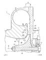
- FIG. 1 is an enlarged view of an arrow portion I in FIG. Fig.2 (a) is an enlarged view of arrow part II in FIG. 1
- FIG.2 (b) and FIG.2 (c) are figures which show a different aspect of a level
- FIG. 3 is a front sectional view showing a centrifugal compressor and the like according to an embodiment of the present invention.
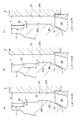
- Fig.4 (a) is a schematic diagram which shows the structure of the periphery of the diffuser which concerns on an invention example
- FIG.4 (b) is a schematic diagram which shows the structure of the periphery of the diffuser which concerns on a comparative example.
- FIG. 5 (a) and 5 (b) are diagrams showing an area where a low pressure portion is generated in the operation area on the large flow rate side (choke side), and FIG. Is the case of the comparative example.
- 6 (a) and 6 (b) are diagrams showing static pressure distributions in the scroll and the diffuser in the working area near the peak of the compressor efficiency, and
- FIG. b) is a case of a comparative example.
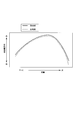
- FIG. 7 is a view showing the relationship between the flow rate and the compressor efficiency in the invention example and the comparative example.
- the present invention is based on the following new findings.
- the novel finding is that the annular step portion 35 is formed.
- Development of flow separation (peeling vortices) is suppressed at the outlet 27o side of the shroud side wall surface 27s of the diffuser 27 during operation of the centrifugal compressor, as compared to the case where no is formed (see FIG. 4 (b))
- the low pressure portion LP due to the peeling is reduced (see FIGS. 5A and 5B).
- FIG. 4A is a schematic view showing the configuration around the diffuser 27 according to the invention example.
- FIG. 4B is a schematic view showing the configuration around the diffuser 27 according to the comparative example.
- 5 (a) and 5 (b) are diagrams showing a region where a low pressure portion is generated in the operation region on the large flow rate side (choke side)
- FIG. 5 (a) is a diagram in the case of the invention example.
- 5 (b) is the case of the comparative example.
- the region where the low pressure portion LP is generated is obtained by computational fluid analysis (CFD: Computational Fluid Dynamics analysis).
- CFD computational Fluid Dynamics analysis
- FIGS. 1 to 3 As shown in the drawings, “L” is in the left direction, and “R” is in the right direction.
- the centrifugal compressor 1 which concerns on embodiment of this invention is used for the supercharger 3, and compresses air using a centrifugal force.
- the centrifugal compressor 1 includes a housing (compressor housing) 5.
- the housing 5 includes a housing body 7 having a shroud 7 s inside, and a seal plate 9 provided on the right side of the housing body 7.
- the seal plate 9 is integrally connected to another housing (bearing housing) 11 in the turbocharger 3.
- an impeller (compressor impeller) 13 is rotatably provided about its axis C.
- the impeller 13 is integrally connected to the left end of the rotating shaft 19.
- the rotating shaft 19 is rotatably provided in another housing 11 via a plurality of thrust bearings 15 and a plurality (only one is shown) of radial bearings 17.
- the impeller 13 also includes a disk 21.
- the disk 21 has a hub surface 21 h.
- the hub surface 21 h extends outward in the radial direction (radial direction of the impeller 13) from the left direction (one side in the axial direction of the impeller 13).
- a plurality of blades 23 having the same axial length are integrally formed on the hub surface 21 h of the disk 21 at intervals in the circumferential direction.
- the leading edge 23 t of each blade 23 extends along the shroud 7 s of the housing body 7. Note that, instead of using a plurality of blades 23 having the same axial length, a plurality of blades (not shown) having different axial lengths may be used.
- An inlet (introduction channel) 25 is formed on the inlet side of the impeller 13 in the housing body 7.
- the inlet 25 introduces air into the housing 5. Further, the inlet 25 is connected to an air cleaner (not shown) for purifying the air.
- a diffuser (diffuser channel) 27 is formed on the outlet side of the impeller 13 in the housing 5. The diffuser 27 decelerates and boosts the compressed air (compressed air).
- the diffuser 27 is formed, for example, in an annular shape.
- a throttle portion (throttling channel) 29 is formed between the impeller 13 and the diffuser 27 in the housing 5. The flow passage width of the throttling portion 29 gradually decreases along the main flow direction.
- the throttling portion 29 is formed, for example, in an annular shape.
- the throttling portion 29 communicates with the diffuser 27.
- a scroll (scroll flow path) 31 is formed on the outlet side of the diffuser 27 in the housing 5.
- the scroll 31 is formed in a spiral shape.
- the scroll 31 is in communication with the diffuser 27.
- the cross-sectional area of the scroll 31 is larger at the winding end side (downstream side) than at the winding start side (upstream side).
- a discharge port (discharge flow path) 33 is formed at an appropriate position of the housing body 7.
- the discharge port 33 discharges the compressed air to the outside of the housing 5.
- the discharge port 33 communicates with the scroll 31 and is connected to an engine-side intake pipe (not shown) such as an intake manifold or an intercooler of the engine.
- the shroud side wall surface 27s and the hub side wall surface 27h of the diffuser 27 are provided to extend in the radial direction (the radial direction of the impeller 13). For example, they may be parallel to the radial direction.
- the shroud side wall surface 27s refers to a wall surface located on the radially outer side of the shroud 7s of the housing body 7.
- the hub side wall surface 27 h refers to a wall surface located on the side where the hub surface 21 h of the disk 21 extends radially outward.
- the above-mentioned parallelism does not have to be exact. That is, the shroud side wall surface 27s and the hub side wall surface 27h may be inclined at an angle of several degrees with respect to the radial direction.
- a plurality of annular step portions 35 are formed in the middle of the shroud side wall surface 27s of the diffuser 27 (between the inlet 27i and the outlet 27o of the diffuser 27). Each step 35 is formed to extend the flow passage width of the diffuser 27 along the main flow direction. Each step 35 locally generates a separation vortex. Each stepped portion 35 is parallel to the flow passage width direction (left and right direction) of the diffuser 27. However, as shown to FIG. 2B, you may incline in linear or curvilinear form with respect to the flow-path width direction of the diffuser 27. As shown in FIG. Furthermore, as shown in FIG. 2C, the number of step portions 35 may be single (one). Here, the above-mentioned parallelism does not have to be exact.
- the step 35 need not be a continuous ring.
- the stepped portion 35 may be provided only in a specific circumferential direction area, such as near the tongue portion on the scroll winding end side.
- machining becomes easy.
- the number of stepped portions 35 can be arbitrarily selected in accordance with engine specifications. However, for example, a single step portion 35 can exert effects on pinpoints in a specific operation region, and by providing a plurality of step portions 35, a single operation in a relatively wide range of operation region, It can be effective.
- two stepped portions 35 can be provided as an example in which a plurality of stepped portions 35 are provided. By providing the two step portions 35, it is possible to minimize the time and effort required for processing the step portions, and to exhibit the effect in a wide range as compared with a single step.
- the step amount ⁇ of the step portion 35 is 5 to 30%, preferably 10 to 20% (0.05 to 0.30 times, preferably 0.10 to 0.3) of the flow path width ⁇ of the outlet 27 o of the diffuser 27. It is set to 20 times). If the step amount ⁇ is set to 5% or more of the flow path width ⁇ , if it is less than 5%, a peeling vortex with sufficient strength (vortex) near the step portion 35 is locally generated. Because it may be difficult. On the other hand, the step amount ⁇ is set to less than 30% of the flow channel width ⁇ because if it exceeds 30%, there is a possibility that the peeling vortices (peeling) generated by the step portion 35 may increase.
- the shroud side wall surface 27 s of the diffuser 27 has a portion that is continuous (adjacent) to the radially outer side of the stepped portion 35.
- the radial length ⁇ of this portion is set to 5 to 30 times, preferably 10 to 20 times, the step amount ⁇ of the step portion 35.
- the length ⁇ is set to five times or more of the step amount ⁇ , it is less than five times that the main flow along the shroud sidewall surface 27s of the diffuser 27 on the front side of the outlet 27o of the diffuser 27 It may be difficult to On the other hand, when the length ⁇ is set to 30 times or less of the step portion 35, if it exceeds 30 times, a new flow of separation vortex (peeling off the front side of the outlet 27o of the diffuser 27 on the shroud side wall surface 27s of the diffuser 27) ), And the effective flow area in the diffuser 27 may be reduced.
- Air introduced into the housing 5 from the inlet 25 can be compressed by rotating the impeller 13 integrally with the rotation shaft 19 around its axis by driving of a radial turbine (not shown) in the turbocharger 3. it can. Then, the compressed air (compressed air) is boosted while being decelerated by the diffuser 27, and is discharged to the outside of the housing 5 from the discharge port 33 via the scroll 31.
- the shroud side wall surface 27s and the hub side wall surface 27h of the diffuser 27 are respectively parallel to the radial direction. Further, an annular step portion 35 is formed at an intermediate portion of the shroud side wall surface 27s of the diffuser 27 so as to expand the flow passage width of the diffuser 27 along the main flow direction. Therefore, applying the above-mentioned new findings, during the operation of the centrifugal compressor 1 (the operation of the supercharger 3), the development of flow separation (a separation vortex) at the outlet 27o side of the diffuser 27 in the shroud side wall surface 27s. Can be reduced, and the low pressure part (blockage, low pressure area, closed area) due to the exfoliation can be reduced.
- the embodiment of the present invention it is possible to suppress the development of flow separation on the outlet side 27 o of the diffuser 27 at the shroud side wall surface 27 s during operation of the centrifugal compressor 1. Therefore, the reduction of the effective flow passage area on the outlet 27o side of the diffuser 27 can be suppressed. Therefore, the main flow can be sufficiently decelerated by the diffuser 27. In addition, during operation of the centrifugal compressor 1, the low pressure portion LP can be reduced due to flow separation on the outlet 27o side of the diffuser 27 at the shroud side wall surface 27s.
- the collision (interference) between the low pressure portion LP and the main flow in the scroll 31 is alleviated, and the occurrence of disturbance in the main flow in the discharge port 33 located on the downstream side of the scroll 31 can be suppressed. it can. Therefore, according to the embodiment of the present invention, the compressor efficiency of the centrifugal compressor 1 can be improved while improving the static pressure recovery performance of the diffuser 27.
- the present invention is not limited to the description of the above-described embodiment.
- the technical idea applied to the centrifugal compressor 1 may be applied to a gas turbine, an industrial air facility, etc.
- the present invention can be implemented in various other manners, such as disposing (not shown) at intervals in the circumferential direction. Further, the scope of rights included in the present invention is not limited to these embodiments.
- FIG. 6 Embodiments of the present invention will be described with reference to FIGS. 6 (a), 6 (b) and 7.
- FIG. 6 (a), 6 (b) and 7. FIG. 6
Landscapes
- Engineering & Computer Science (AREA)
- Mechanical Engineering (AREA)
- General Engineering & Computer Science (AREA)
- Chemical & Material Sciences (AREA)
- Combustion & Propulsion (AREA)
- Structures Of Non-Positive Displacement Pumps (AREA)
- Supercharger (AREA)
Abstract
Priority Applications (4)
| Application Number | Priority Date | Filing Date | Title |
|---|---|---|---|
| CN201480032889.XA CN105339675A (zh) | 2013-08-06 | 2014-07-29 | 离心压缩机以及增压器 |
| JP2015530830A JP6323454B2 (ja) | 2013-08-06 | 2014-07-29 | 遠心圧縮機及び過給機 |
| EP14834428.6A EP3032108B8 (fr) | 2013-08-06 | 2014-07-29 | Compresseur centrifuge et compresseur d'alimentation |
| US14/950,094 US10066638B2 (en) | 2013-08-06 | 2015-11-24 | Centrifugal compressor and turbocharger |
Applications Claiming Priority (2)
| Application Number | Priority Date | Filing Date | Title |
|---|---|---|---|
| JP2013162984 | 2013-08-06 | ||
| JP2013-162984 | 2013-08-06 |
Related Child Applications (1)
| Application Number | Title | Priority Date | Filing Date |
|---|---|---|---|
| US14/950,094 Continuation US10066638B2 (en) | 2013-08-06 | 2015-11-24 | Centrifugal compressor and turbocharger |
Publications (1)
| Publication Number | Publication Date |
|---|---|
| WO2015019901A1 true WO2015019901A1 (fr) | 2015-02-12 |
Family
ID=52461239
Family Applications (1)
| Application Number | Title | Priority Date | Filing Date |
|---|---|---|---|
| PCT/JP2014/069936 Ceased WO2015019901A1 (fr) | 2013-08-06 | 2014-07-29 | Compresseur centrifuge et compresseur d'alimentation |
Country Status (5)
| Country | Link |
|---|---|
| US (1) | US10066638B2 (fr) |
| EP (1) | EP3032108B8 (fr) |
| JP (1) | JP6323454B2 (fr) |
| CN (1) | CN105339675A (fr) |
| WO (1) | WO2015019901A1 (fr) |
Cited By (5)
| Publication number | Priority date | Publication date | Assignee | Title |
|---|---|---|---|---|
| CN104819166A (zh) * | 2015-05-11 | 2015-08-05 | 山东赛马力发电设备有限公司 | 一种减少增压器压气机漏油的装置及方法 |
| CN106837858A (zh) * | 2017-01-05 | 2017-06-13 | 上海交通大学 | 锯齿阻流结构 |
| WO2017140852A1 (fr) * | 2016-02-19 | 2017-08-24 | Abb Turbo Systems Ag | Diffuseur de compresseur centrifuge |
| CN107614886A (zh) * | 2015-10-29 | 2018-01-19 | 三菱重工业株式会社 | 涡壳以及离心压缩机 |
| JP2020511609A (ja) * | 2017-03-08 | 2020-04-16 | ロベルト・ボッシュ・ゲゼルシャフト・ミト・ベシュレンクテル・ハフツングRobert Bosch Gmbh | 遠心ターボ圧縮機 |
Families Citing this family (20)
| Publication number | Priority date | Publication date | Assignee | Title |
|---|---|---|---|---|
| KR102104415B1 (ko) * | 2015-02-05 | 2020-04-24 | 한화파워시스템 주식회사 | 압축기 |
| GB2551804B (en) * | 2016-06-30 | 2021-04-07 | Cummins Ltd | Diffuser for a centrifugal compressor |
| CN107061356B (zh) * | 2017-01-05 | 2020-01-07 | 上海交通大学 | 凹槽阻流结构 |
| CN106640754B (zh) * | 2017-01-05 | 2020-06-12 | 上海交通大学 | 带有环形突起结构的新型离心压气机 |
| JP6908472B2 (ja) * | 2017-08-31 | 2021-07-28 | 三菱重工コンプレッサ株式会社 | 遠心圧縮機 |
| EP3460257A1 (fr) * | 2017-09-20 | 2019-03-27 | Siemens Aktiengesellschaft | Dispositif pouvant être traversé |
| EP3460256A1 (fr) * | 2017-09-20 | 2019-03-27 | Siemens Aktiengesellschaft | Dispositif pouvant être traversé |
| DE102017127758A1 (de) * | 2017-11-24 | 2019-05-29 | Man Diesel & Turbo Se | Radialverdichter und Turbolader |
| DE102018115446A1 (de) * | 2018-06-27 | 2020-01-02 | Ihi Charging Systems International Gmbh | Abgasturbolader |
| US10935045B2 (en) * | 2018-07-19 | 2021-03-02 | GM Global Technology Operations LLC | Centrifugal compressor with inclined diffuser |
| WO2020039919A1 (fr) * | 2018-08-23 | 2020-02-27 | 株式会社Ihi | Compresseur centrifuge |
| DE102018215888A1 (de) * | 2018-09-19 | 2020-03-19 | Robert Bosch Gmbh | Verdichter |
| US11131236B2 (en) * | 2019-03-13 | 2021-09-28 | Garrett Transportation I Inc. | Turbocharger having adjustable-trim centrifugal compressor including divergent-wall diffuser |
| CN111120400A (zh) * | 2019-12-24 | 2020-05-08 | 哈尔滨工程大学 | 一种用于微型燃机的离心压气机 |
| CN112879349B (zh) * | 2021-01-15 | 2022-04-19 | 宁波方太厨具有限公司 | 一种进风装置、应用有该进风装置的风机系统和清洁机 |
| US20230093314A1 (en) * | 2021-09-17 | 2023-03-23 | Carrier Corporation | Passive flow reversal reduction in compressor assembly |
| CN114645858B (zh) * | 2022-03-15 | 2024-07-23 | 天津大学 | 发动机变工况下离心压气机性能测试台架装置 |
| US11788557B1 (en) * | 2022-05-06 | 2023-10-17 | Ingersoll-Rand Industrial U.S., Inc. | Centrifugal acceleration stabilizer |
| US12297844B2 (en) | 2022-11-13 | 2025-05-13 | Borgwarner Inc. | Controlled area progression diffuser |
| US20250354565A1 (en) * | 2024-05-20 | 2025-11-20 | Borgwarner Inc. | Controlled Area Progression Vaned Diffuser |
Citations (15)
| Publication number | Priority date | Publication date | Assignee | Title |
|---|---|---|---|---|
| JPS6070798U (ja) * | 1983-10-24 | 1985-05-18 | 三菱重工業株式会社 | 遠心式流体機械 |
| JPS6184199U (fr) * | 1984-11-08 | 1986-06-03 | ||
| JPS62188598U (fr) * | 1986-05-23 | 1987-12-01 | ||
| JPH0212097U (fr) * | 1988-07-08 | 1990-01-25 | ||
| JPH078597U (ja) * | 1993-07-06 | 1995-02-07 | 三菱重工業株式会社 | 遠心圧縮機 |
| JPH10176699A (ja) * | 1996-12-18 | 1998-06-30 | Ishikawajima Harima Heavy Ind Co Ltd | 遠心圧縮機 |
| JP2006220053A (ja) | 2005-02-10 | 2006-08-24 | Mitsubishi Heavy Ind Ltd | 可変容量型排気ターボ過給機のスクロール構造及びその製造方法 |
| JP2008510100A (ja) * | 2004-08-19 | 2008-04-03 | ハネウェル・インターナショナル・インコーポレーテッド | 圧縮機翼車ハウジング |
| JP2008163821A (ja) * | 2006-12-28 | 2008-07-17 | Toyota Central R&D Labs Inc | 遠心圧縮機 |
| JP2009002305A (ja) | 2007-06-25 | 2009-01-08 | Toyota Motor Corp | 過給機 |
| JP2010196542A (ja) | 2009-02-24 | 2010-09-09 | Toyota Motor Corp | 遠心圧縮機、及びターボ過給機 |
| JP2012041844A (ja) * | 2010-08-17 | 2012-03-01 | Toyota Motor Corp | 遠心圧縮機 |
| JP2013204550A (ja) * | 2012-03-29 | 2013-10-07 | Mitsubishi Heavy Ind Ltd | 遠心圧縮機 |
| JP2014074389A (ja) * | 2012-10-05 | 2014-04-24 | Ihi Corp | 遠心圧縮機 |
| JP2014074390A (ja) * | 2012-10-05 | 2014-04-24 | Ihi Corp | 遠心圧縮機 |
Family Cites Families (9)
| Publication number | Priority date | Publication date | Assignee | Title |
|---|---|---|---|---|
| US4181466A (en) * | 1977-03-17 | 1980-01-01 | Wallace Murray Corp. | Centrifugal compressor and cover |
| US4251183A (en) * | 1978-01-30 | 1981-02-17 | The Garrett Corp. | Crossover duct assembly |
| US4378194A (en) * | 1980-10-02 | 1983-03-29 | Carrier Corporation | Centrifugal compressor |
| JPS58183899A (ja) | 1982-04-21 | 1983-10-27 | Hitachi Ltd | 羽根付デイフユ−ザ |
| JP3153409B2 (ja) * | 1994-03-18 | 2001-04-09 | 株式会社日立製作所 | 遠心圧縮機の製作方法 |
| JP2005240681A (ja) | 2004-02-26 | 2005-09-08 | Mitsubishi Heavy Ind Ltd | 軸流ファン |
| DE102008036633B4 (de) * | 2008-08-06 | 2019-06-19 | Continental Mechanical Components Germany Gmbh | Turbolader mit einem Einlegeblech |
| FR2942267B1 (fr) * | 2009-02-19 | 2011-05-06 | Turbomeca | Temoin d'erosion pour roue de compresseur |
| JP5535562B2 (ja) | 2009-09-16 | 2014-07-02 | 三菱重工業株式会社 | 排出スクロール及びターボ機械 |
-
2014
- 2014-07-29 WO PCT/JP2014/069936 patent/WO2015019901A1/fr not_active Ceased
- 2014-07-29 JP JP2015530830A patent/JP6323454B2/ja active Active
- 2014-07-29 EP EP14834428.6A patent/EP3032108B8/fr active Active
- 2014-07-29 CN CN201480032889.XA patent/CN105339675A/zh active Pending
-
2015
- 2015-11-24 US US14/950,094 patent/US10066638B2/en active Active
Patent Citations (15)
| Publication number | Priority date | Publication date | Assignee | Title |
|---|---|---|---|---|
| JPS6070798U (ja) * | 1983-10-24 | 1985-05-18 | 三菱重工業株式会社 | 遠心式流体機械 |
| JPS6184199U (fr) * | 1984-11-08 | 1986-06-03 | ||
| JPS62188598U (fr) * | 1986-05-23 | 1987-12-01 | ||
| JPH0212097U (fr) * | 1988-07-08 | 1990-01-25 | ||
| JPH078597U (ja) * | 1993-07-06 | 1995-02-07 | 三菱重工業株式会社 | 遠心圧縮機 |
| JPH10176699A (ja) * | 1996-12-18 | 1998-06-30 | Ishikawajima Harima Heavy Ind Co Ltd | 遠心圧縮機 |
| JP2008510100A (ja) * | 2004-08-19 | 2008-04-03 | ハネウェル・インターナショナル・インコーポレーテッド | 圧縮機翼車ハウジング |
| JP2006220053A (ja) | 2005-02-10 | 2006-08-24 | Mitsubishi Heavy Ind Ltd | 可変容量型排気ターボ過給機のスクロール構造及びその製造方法 |
| JP2008163821A (ja) * | 2006-12-28 | 2008-07-17 | Toyota Central R&D Labs Inc | 遠心圧縮機 |
| JP2009002305A (ja) | 2007-06-25 | 2009-01-08 | Toyota Motor Corp | 過給機 |
| JP2010196542A (ja) | 2009-02-24 | 2010-09-09 | Toyota Motor Corp | 遠心圧縮機、及びターボ過給機 |
| JP2012041844A (ja) * | 2010-08-17 | 2012-03-01 | Toyota Motor Corp | 遠心圧縮機 |
| JP2013204550A (ja) * | 2012-03-29 | 2013-10-07 | Mitsubishi Heavy Ind Ltd | 遠心圧縮機 |
| JP2014074389A (ja) * | 2012-10-05 | 2014-04-24 | Ihi Corp | 遠心圧縮機 |
| JP2014074390A (ja) * | 2012-10-05 | 2014-04-24 | Ihi Corp | 遠心圧縮機 |
Non-Patent Citations (1)
| Title |
|---|
| See also references of EP3032108A4 * |
Cited By (11)
| Publication number | Priority date | Publication date | Assignee | Title |
|---|---|---|---|---|
| CN104819166A (zh) * | 2015-05-11 | 2015-08-05 | 山东赛马力发电设备有限公司 | 一种减少增压器压气机漏油的装置及方法 |
| CN107614886A (zh) * | 2015-10-29 | 2018-01-19 | 三菱重工业株式会社 | 涡壳以及离心压缩机 |
| EP3299635A4 (fr) * | 2015-10-29 | 2018-05-30 | Mitsubishi Heavy Industries, Ltd. | Carter en spirale et compresseur centrifuge |
| US11078922B2 (en) | 2015-10-29 | 2021-08-03 | Mitsubishi Heavy Industries Engine & Turbocharger, Ltd. | Scroll casing and centrifugal compressor |
| WO2017140852A1 (fr) * | 2016-02-19 | 2017-08-24 | Abb Turbo Systems Ag | Diffuseur de compresseur centrifuge |
| CN109072939A (zh) * | 2016-02-19 | 2018-12-21 | Abb涡轮系统有限公司 | 径流式压缩机的扩压器 |
| CN106837858A (zh) * | 2017-01-05 | 2017-06-13 | 上海交通大学 | 锯齿阻流结构 |
| CN106837858B (zh) * | 2017-01-05 | 2020-01-07 | 上海交通大学 | 锯齿阻流结构 |
| JP2020511609A (ja) * | 2017-03-08 | 2020-04-16 | ロベルト・ボッシュ・ゲゼルシャフト・ミト・ベシュレンクテル・ハフツングRobert Bosch Gmbh | 遠心ターボ圧縮機 |
| US11242857B2 (en) | 2017-03-08 | 2022-02-08 | Robert Bosch Gmbh | Centrifugal turbo-compressor |
| JP7110219B2 (ja) | 2017-03-08 | 2022-08-01 | ロベルト・ボッシュ・ゲゼルシャフト・ミト・ベシュレンクテル・ハフツング | 遠心ターボ圧縮機 |
Also Published As
| Publication number | Publication date |
|---|---|
| EP3032108B1 (fr) | 2020-02-19 |
| JPWO2015019901A1 (ja) | 2017-03-02 |
| US10066638B2 (en) | 2018-09-04 |
| EP3032108A1 (fr) | 2016-06-15 |
| JP6323454B2 (ja) | 2018-05-16 |
| CN105339675A (zh) | 2016-02-17 |
| EP3032108B8 (fr) | 2020-06-17 |
| US20160076553A1 (en) | 2016-03-17 |
| EP3032108A4 (fr) | 2017-03-29 |
Similar Documents
| Publication | Publication Date | Title |
|---|---|---|
| JP6323454B2 (ja) | 遠心圧縮機及び過給機 | |
| US7575412B2 (en) | Anti-stall casing treatment for turbo compressors | |
| CA2496543C (fr) | Structure de recirculation d'un turbocompresseur | |
| JP6468414B2 (ja) | 圧縮機静翼、軸流圧縮機、及びガスタービン | |
| EP2803866B1 (fr) | Compresseur centrifuge avec traitement de carter pour le contrôle de pompage | |
| US10330102B2 (en) | Centrifugal compressor and turbocharger | |
| CN101560987A (zh) | 带有喘振控制的离心式压缩机及有关方法 | |
| US10221858B2 (en) | Impeller blade morphology | |
| WO2015076102A1 (fr) | Compresseur centrifuge et compresseur d'alimentation | |
| JP2010144698A (ja) | 遠心圧縮機 | |
| WO2018181343A1 (fr) | Compresseur centrifuge | |
| US10138898B2 (en) | Centrifugal compressor and turbocharger | |
| JP2009197613A (ja) | 遠心圧縮機及びディフューザベーンユニット | |
| JP6357830B2 (ja) | 圧縮機インペラ、遠心圧縮機、及び過給機 | |
| JP6349645B2 (ja) | 遠心圧縮機及び多段圧縮装置 | |
| JP5251587B2 (ja) | 遠心圧縮機 | |
| WO2018155546A1 (fr) | Compresseur centrifuge | |
| JP2018178769A (ja) | 多段流体機械 | |
| JP2015040505A (ja) | 遠心圧縮機及び過給機 | |
| JP2015075013A (ja) | 遠心圧縮機 | |
| JP5428962B2 (ja) | 軸流圧縮機及びガスタービンエンジン | |
| JP2009197614A (ja) | 遠心圧縮機及びディフューザベーン |
Legal Events
| Date | Code | Title | Description |
|---|---|---|---|
| WWE | Wipo information: entry into national phase |
Ref document number: 201480032889.X Country of ref document: CN |
|
| 121 | Ep: the epo has been informed by wipo that ep was designated in this application |
Ref document number: 14834428 Country of ref document: EP Kind code of ref document: A1 |
|
| ENP | Entry into the national phase |
Ref document number: 2015530830 Country of ref document: JP Kind code of ref document: A |
|
| WWE | Wipo information: entry into national phase |
Ref document number: 2014834428 Country of ref document: EP |
|
| NENP | Non-entry into the national phase |
Ref country code: DE |