WO2015029451A1 - 防水通気膜とそれを備える防水通気部材および防水通気構造ならびに防水通音膜 - Google Patents
防水通気膜とそれを備える防水通気部材および防水通気構造ならびに防水通音膜 Download PDFInfo
- Publication number
- WO2015029451A1 WO2015029451A1 PCT/JP2014/004452 JP2014004452W WO2015029451A1 WO 2015029451 A1 WO2015029451 A1 WO 2015029451A1 JP 2014004452 W JP2014004452 W JP 2014004452W WO 2015029451 A1 WO2015029451 A1 WO 2015029451A1
- Authority
- WO
- WIPO (PCT)
- Prior art keywords
- sound
- waterproof
- film
- resin film
- membrane
- Prior art date
- Legal status (The legal status is an assumption and is not a legal conclusion. Google has not performed a legal analysis and makes no representation as to the accuracy of the status listed.)
- Ceased
Links
Images


Classifications
-
- B—PERFORMING OPERATIONS; TRANSPORTING
- B01—PHYSICAL OR CHEMICAL PROCESSES OR APPARATUS IN GENERAL
- B01D—SEPARATION
- B01D67/00—Processes specially adapted for manufacturing semi-permeable membranes for separation processes or apparatus
- B01D67/0002—Organic membrane manufacture
- B01D67/0023—Organic membrane manufacture by inducing porosity into non porous precursor membranes
- B01D67/0032—Organic membrane manufacture by inducing porosity into non porous precursor membranes by elimination of segments of the precursor, e.g. nucleation-track membranes, lithography or laser methods
-
- B—PERFORMING OPERATIONS; TRANSPORTING
- B01—PHYSICAL OR CHEMICAL PROCESSES OR APPARATUS IN GENERAL
- B01D—SEPARATION
- B01D67/00—Processes specially adapted for manufacturing semi-permeable membranes for separation processes or apparatus
- B01D67/0081—After-treatment of organic or inorganic membranes
- B01D67/0088—Physical treatment with compounds, e.g. swelling, coating or impregnation
-
- B—PERFORMING OPERATIONS; TRANSPORTING
- B01—PHYSICAL OR CHEMICAL PROCESSES OR APPARATUS IN GENERAL
- B01D—SEPARATION
- B01D69/00—Semi-permeable membranes for separation processes or apparatus characterised by their form, structure or properties; Manufacturing processes specially adapted therefor
- B01D69/10—Supported membranes; Membrane supports
- B01D69/107—Organic support material
- B01D69/1071—Woven, non-woven or net mesh
-
- B—PERFORMING OPERATIONS; TRANSPORTING
- B01—PHYSICAL OR CHEMICAL PROCESSES OR APPARATUS IN GENERAL
- B01D—SEPARATION
- B01D69/00—Semi-permeable membranes for separation processes or apparatus characterised by their form, structure or properties; Manufacturing processes specially adapted therefor
- B01D69/12—Composite membranes; Ultra-thin membranes
- B01D69/1213—Laminated layers
-
- B—PERFORMING OPERATIONS; TRANSPORTING
- B01—PHYSICAL OR CHEMICAL PROCESSES OR APPARATUS IN GENERAL
- B01D—SEPARATION
- B01D71/00—Semi-permeable membranes for separation processes or apparatus characterised by the material; Manufacturing processes specially adapted therefor
- B01D71/06—Organic material
- B01D71/48—Polyesters
-
- B—PERFORMING OPERATIONS; TRANSPORTING
- B32—LAYERED PRODUCTS
- B32B—LAYERED PRODUCTS, i.e. PRODUCTS BUILT-UP OF STRATA OF FLAT OR NON-FLAT, e.g. CELLULAR OR HONEYCOMB, FORM
- B32B27/00—Layered products comprising a layer of synthetic resin
- B32B27/06—Layered products comprising a layer of synthetic resin as the main or only constituent of a layer, which is next to another layer of the same or of a different material
-
- B—PERFORMING OPERATIONS; TRANSPORTING
- B32—LAYERED PRODUCTS
- B32B—LAYERED PRODUCTS, i.e. PRODUCTS BUILT-UP OF STRATA OF FLAT OR NON-FLAT, e.g. CELLULAR OR HONEYCOMB, FORM
- B32B3/00—Layered products comprising a layer with external or internal discontinuities or unevennesses, or a layer of non-planar shape; Layered products comprising a layer having particular features of form
- B32B3/02—Layered products comprising a layer with external or internal discontinuities or unevennesses, or a layer of non-planar shape; Layered products comprising a layer having particular features of form characterised by features of form at particular places, e.g. in edge regions
- B32B3/04—Layered products comprising a layer with external or internal discontinuities or unevennesses, or a layer of non-planar shape; Layered products comprising a layer having particular features of form characterised by features of form at particular places, e.g. in edge regions characterised by at least one layer folded at the edge, e.g. over another layer ; characterised by at least one layer enveloping or enclosing a material
-
- B—PERFORMING OPERATIONS; TRANSPORTING
- B32—LAYERED PRODUCTS
- B32B—LAYERED PRODUCTS, i.e. PRODUCTS BUILT-UP OF STRATA OF FLAT OR NON-FLAT, e.g. CELLULAR OR HONEYCOMB, FORM
- B32B3/00—Layered products comprising a layer with external or internal discontinuities or unevennesses, or a layer of non-planar shape; Layered products comprising a layer having particular features of form
- B32B3/26—Layered products comprising a layer with external or internal discontinuities or unevennesses, or a layer of non-planar shape; Layered products comprising a layer having particular features of form characterised by a particular shape of the outline of the cross-section of a continuous layer; characterised by a layer with cavities or internal voids ; characterised by an apertured layer
- B32B3/266—Layered products comprising a layer with external or internal discontinuities or unevennesses, or a layer of non-planar shape; Layered products comprising a layer having particular features of form characterised by a particular shape of the outline of the cross-section of a continuous layer; characterised by a layer with cavities or internal voids ; characterised by an apertured layer characterised by an apertured layer, the apertures going through the whole thickness of the layer, e.g. expanded metal, perforated layer, slit layer regular cells B32B3/12
-
- H—ELECTRICITY
- H04—ELECTRIC COMMUNICATION TECHNIQUE
- H04R—LOUDSPEAKERS, MICROPHONES, GRAMOPHONE PICK-UPS OR LIKE ACOUSTIC ELECTROMECHANICAL TRANSDUCERS; ELECTRIC HEARING AIDS; PUBLIC ADDRESS SYSTEMS
- H04R1/00—Details of transducers, loudspeakers or microphones
- H04R1/02—Casings; Cabinets ; Supports therefor; Mountings therein
- H04R1/023—Screens for loudspeakers
-
- H—ELECTRICITY
- H04—ELECTRIC COMMUNICATION TECHNIQUE
- H04R—LOUDSPEAKERS, MICROPHONES, GRAMOPHONE PICK-UPS OR LIKE ACOUSTIC ELECTROMECHANICAL TRANSDUCERS; ELECTRIC HEARING AIDS; PUBLIC ADDRESS SYSTEMS
- H04R1/00—Details of transducers, loudspeakers or microphones
- H04R1/08—Mouthpieces; Microphones; Attachments therefor
- H04R1/083—Special constructions of mouthpieces
- H04R1/086—Protective screens, e.g. all weather or wind screens
-
- H—ELECTRICITY
- H05—ELECTRIC TECHNIQUES NOT OTHERWISE PROVIDED FOR
- H05K—PRINTED CIRCUITS; CASINGS OR CONSTRUCTIONAL DETAILS OF ELECTRIC APPARATUS; MANUFACTURE OF ASSEMBLAGES OF ELECTRICAL COMPONENTS
- H05K5/00—Casings, cabinets or drawers for electric apparatus
- H05K5/02—Details
- H05K5/0213—Venting apertures; Constructional details thereof
- H05K5/0215—Venting apertures; Constructional details thereof with semi-permeable membranes attached to casings
-
- B—PERFORMING OPERATIONS; TRANSPORTING
- B01—PHYSICAL OR CHEMICAL PROCESSES OR APPARATUS IN GENERAL
- B01D—SEPARATION
- B01D2325/00—Details relating to properties of membranes
- B01D2325/38—Hydrophobic membranes
-
- B—PERFORMING OPERATIONS; TRANSPORTING
- B32—LAYERED PRODUCTS
- B32B—LAYERED PRODUCTS, i.e. PRODUCTS BUILT-UP OF STRATA OF FLAT OR NON-FLAT, e.g. CELLULAR OR HONEYCOMB, FORM
- B32B2307/00—Properties of the layers or laminate
- B32B2307/10—Properties of the layers or laminate having particular acoustical properties
-
- B—PERFORMING OPERATIONS; TRANSPORTING
- B32—LAYERED PRODUCTS
- B32B—LAYERED PRODUCTS, i.e. PRODUCTS BUILT-UP OF STRATA OF FLAT OR NON-FLAT, e.g. CELLULAR OR HONEYCOMB, FORM
- B32B2307/00—Properties of the layers or laminate
- B32B2307/70—Other properties
- B32B2307/724—Permeability to gases, adsorption
-
- B—PERFORMING OPERATIONS; TRANSPORTING
- B32—LAYERED PRODUCTS
- B32B—LAYERED PRODUCTS, i.e. PRODUCTS BUILT-UP OF STRATA OF FLAT OR NON-FLAT, e.g. CELLULAR OR HONEYCOMB, FORM
- B32B2307/00—Properties of the layers or laminate
- B32B2307/70—Other properties
- B32B2307/726—Permeability to liquids, absorption
- B32B2307/7265—Non-permeable
-
- B—PERFORMING OPERATIONS; TRANSPORTING
- B32—LAYERED PRODUCTS
- B32B—LAYERED PRODUCTS, i.e. PRODUCTS BUILT-UP OF STRATA OF FLAT OR NON-FLAT, e.g. CELLULAR OR HONEYCOMB, FORM
- B32B2307/00—Properties of the layers or laminate
- B32B2307/70—Other properties
- B32B2307/73—Hydrophobic
-
- B—PERFORMING OPERATIONS; TRANSPORTING
- B32—LAYERED PRODUCTS
- B32B—LAYERED PRODUCTS, i.e. PRODUCTS BUILT-UP OF STRATA OF FLAT OR NON-FLAT, e.g. CELLULAR OR HONEYCOMB, FORM
- B32B2457/00—Electrical equipment
-
- H—ELECTRICITY
- H04—ELECTRIC COMMUNICATION TECHNIQUE
- H04R—LOUDSPEAKERS, MICROPHONES, GRAMOPHONE PICK-UPS OR LIKE ACOUSTIC ELECTROMECHANICAL TRANSDUCERS; ELECTRIC HEARING AIDS; PUBLIC ADDRESS SYSTEMS
- H04R2499/00—Aspects covered by H04R or H04S not otherwise provided for in their subgroups
- H04R2499/10—General applications
- H04R2499/11—Transducers incorporated or for use in hand-held devices, e.g. mobile phones, PDA's, camera's
Definitions
- the present invention relates to a waterproof breathable membrane having both waterproof properties and breathability, a waterproof vent member and a waterproof vent structure having the waterproof breathable membrane.
- the present invention also relates to a waterproof sound-permeable membrane having both waterproof properties and sound-transmitting properties.
- An opening for ensuring air permeability between the outside and the inside of the casing is often provided in a casing of such a home appliance; and a casing of an information terminal such as a mobile phone.
- the pressure difference generated between the inside and the outside of the housing can be eliminated or reduced.
- gas usually air
- a waterproof air-permeable membrane is arranged to prevent water from entering the inside through the opening.
- an opening for transmitting sound between an acoustic part arranged in the casing and the outside of the electronic apparatus is provided in the casing of the electronic apparatus having a voice function such as a mobile phone and a tablet computer.
- the sound unit is, for example, a sound generation unit such as a speaker and / or a sound reception unit such as a microphone. Due to the nature of electronic equipment, water intrusion into the housing must be prevented, but the opening for transmitting sound can easily be a path for water to enter. In particular, portable electronic devices are often exposed to rain and water in daily life, and the direction of the opening cannot be fixed in a certain direction that can avoid water (for example, the downward direction in which rain is difficult to blow). The risk of intrusion increases. Therefore, a waterproof sound-permeable membrane that transmits sound between the acoustic unit and the outside and prevents water from entering the housing through the opening from the outside is disposed so as to close the opening.
- Patent Documents 1 and 2 disclose a waterproof gas-permeable membrane and a waterproof sound-permeable membrane made of a stretched porous membrane of polytetrafluoroethylene (PTFE), respectively.
- PTFE polytetrafluoroethylene
- Another example of the waterproof breathable membrane and the waterproof sound-permeable membrane is a non-porous resin film in which a plurality of through-holes penetrating in the thickness direction are formed (see Patent Documents 3 and 4).
- the waterproof breathable membrane of the present invention corresponds to the non-porous resin film in which a plurality of through holes penetrating in the thickness direction are formed, and the plurality of through holes formed on the main surface of the resin film. And a liquid repellent layer having an opening at the position.
- the through hole extends linearly and has a diameter of 15 ⁇ m or less.
- the density of the through holes in the resin film is 1 ⁇ 10 3 pieces / cm 2 or more and 1 ⁇ 10 9 pieces / cm 2 or less.
- the said resin film has the said through-hole extended in the direction inclined with respect to the direction perpendicular
- the waterproof ventilation member of the present invention includes the waterproof ventilation membrane of the present invention and a support joined to the waterproof ventilation membrane.
- the waterproof ventilation structure of the present invention is disposed so as to close the housing having an opening and the opening, and allows water to pass through the opening from the outside while allowing gas to pass between the inside and the outside of the housing. And a waterproof breathable membrane that prevents the intrusion of water.
- the waterproof breathable membrane is the waterproof breathable membrane of the present invention.
- the waterproof sound-permeable membrane of the present invention includes a non-porous resin film in which a plurality of through holes penetrating in the thickness direction are formed, and the plurality of through holes formed on the main surface of the resin film.
- a liquid repellent layer having an opening at a corresponding position.
- the through hole extends linearly and has a diameter of 15 ⁇ m or less.
- the density of the through holes in the resin film is 1 ⁇ 10 3 pieces / cm 2 or more and 1 ⁇ 10 9 pieces / cm 2 or less.
- the said resin film has the said through-hole extended in the direction inclined with respect to the direction perpendicular
- a waterproof breathable membrane that achieves both breathability and waterproofness at a higher level than before.
- a waterproof sound-permeable membrane excellent in waterproofness and sound-transmitting characteristics can be obtained.
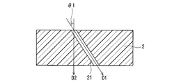
- FIG. 4 is a schematic cross-sectional view for explaining an angle ⁇ 1 formed by a direction in which a through hole is inclined and extended with respect to a direction perpendicular to a main surface of a resin film 2 in the waterproof breathable membrane of the present invention.
- FIG. In the waterproof breathable membrane of the present invention it is a top view showing typically an example of the relation between the through-holes in the direction in which the through-holes extend. In the waterproof breathable membrane of the present invention, it is a top view showing typically another example of the relation between the through holes in the direction in which the through holes extend.
- the waterproof breathable membrane of the present invention is a top view showing typically another example of the relation between the through holes in the direction in which the through holes extend. It is sectional drawing which shows typically an example of the relationship between through-holes in the waterproof breathable film of this invention. It is sectional drawing which shows typically another example of the waterproof breathable film of this invention. It is a schematic diagram which shows an example of the method of manufacturing the waterproof breathable film of this invention. It is sectional drawing which shows typically another example of the waterproof breathable film of this invention. It is a perspective view which shows typically an example of the waterproof ventilation member of this invention. It is a top view which shows typically another example of the waterproof ventilation member of this invention. It is sectional drawing which shows typically an example of the waterproof ventilation structure of this invention.
- FIG. 13A It is a perspective view which shows typically an example of an electronic device provided with the waterproof sound-permeable membrane of this invention. It is sectional drawing which shows typically arrangement
- FIG. 1 shows an example of the waterproof breathable membrane of the present invention.
- a waterproof breathable membrane 1 shown in FIG. 1 includes a non-porous resin film 2 and a liquid repellent layer 3 formed on the main surface of the resin film 2.
- a plurality of through holes 21 (21a to 21g) penetrating in the thickness direction are formed in the resin film 2.
- the liquid repellent layer 3 has an opening 31 at a position corresponding to the through hole 21 (a position corresponding to the opening of the through hole 21 in the resin film 2).
- the resin film 2 is a non-porous resin film that has no path other than the through hole 21 through which air can be passed in the thickness direction. (Real) resin film.
- the through hole 21 has openings on both main surfaces of the resin film 2.
- the through hole 21 is a straight hole extending linearly, that is, penetrating the resin film 2 linearly.
- the through hole 21 can be a hole whose diameter does not substantially change from one main surface of the resin film 2 to the other main surface.
- the through-hole 21 can be formed by, for example, irradiation of an ion beam onto a resin film that is an original film and chemical etching on the film after irradiation. By ion beam irradiation and etching, a large number of through holes 21 having a uniform opening diameter can be formed in the resin film 2.
- Film 2 can be obtained. For this reason, for example, if a film having a high surface smoothness is selected as the original film, a resin film 21 having a surface with a high smoothness corresponding thereto (for example, the surface is flat except for the opening) is obtained. Is possible.
- the original film is a non-porous film that does not have a path that allows air to flow in the thickness direction in the region to be the waterproof breathable membrane 1.
- the original film is typically a nonporous resin film.
- the resin film 2 has a through hole 21 extending in a direction inclined with respect to a direction perpendicular to the main surface of the film.
- through holes 21 a to 21 g having different directions extending in an inclined manner are mixed in the resin film 2.
- the through hole 21 extends in a direction inclined with respect to a direction perpendicular to the main surface of the resin film 2 (through the resin film 2), and the extending directions of the resin film 2 are different from each other.
- the resin film 2 may have a combination of through holes 21 having the same extending direction. In the example shown in FIG.
- the extending directions of the through holes 21a, 21b, and 21c are different from each other, and the extending directions of the through holes 21a, 21d, and 21g are the same.
- “combination” is also simply referred to as “set” in the present specification.
- the “set” is not limited to the relationship (pair) between one through hole and one through hole, and means a relationship between one or two or more through holes. Having a set of through holes having the same characteristics means that there are a plurality of through holes having the characteristics.
- the resin film 2 as shown in FIG. 1 irradiates, for example, an ion beam tilted from a direction perpendicular to the main surface of the original film, and changes the tilting direction continuously or stepwise to change the film after irradiation. It can be formed by chemical etching. Since the ion beam is a beam in which a plurality of ions fly in parallel with each other, a set of through holes 21 extending in the same direction is usually present in the resin film 2 (a plurality of through holes 21 extending in the same direction are the resin film 2). Usually exists).
- Through holes 21 having different directions extending at an angle are mixed in the resin film 2, the diameter of the through holes existing in the resin film 2 is 15 ⁇ m or less, and the hole density of the through holes in the resin film 2 is 1 ⁇ 10 3 pieces / cm 3. 2 and 1 ⁇ 10 9 pieces / cm 2 or less, and having a liquid repellent layer 3 on the main surface of the resin film 2, a waterproof breathable membrane that achieves both breathability and waterproofness at a higher level than before. 1
- the angle ⁇ 1 (see FIG. 2) formed by the inclined direction D1 with respect to the direction D2 perpendicular to the main surface of the resin film 2 is preferably 45 ° or less, and more preferably 30 ° or less.
- the minimum of angle (theta) 1 is not specifically limited, For example, it is 10 degrees or more, and 20 degrees or more are preferable. If the angle ⁇ 1 is excessively large, the mechanical strength of the waterproof gas-permeable membrane 1 tends to be weakened.
- the angle ⁇ 1 can be controlled by, for example, the incident angle of the ion beam with respect to the original film when the resin film 2 is manufactured.
- the extending directions of the through holes 21 are parallel to each other.
- the resin film 2 has a set in which the extending directions are different from each other (through holes 21 having different extending directions are present in the resin film 2). In the latter case, the level of both air permeability and waterproof property as the waterproof gas-permeable membrane 1 is further increased.
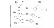
- FIG. 3 shows an example in which the directions in which the through holes 21 extend are parallel to each other when viewed from the direction perpendicular to the main surface of the resin film 2.
- three through holes 21 21 h, 21 i, 21 j
- D3, D4, and D5 are parallel to each other (the direction from the opening 22a of the through hole 21 in the main surface on the side to the opening 22b of the through hole 21 in the main surface on the opposite side) ( ⁇ 2 described later is 0 °).
- angles ⁇ 1 of the through holes 21h, 21i, and 21j are different from each other (the angle ⁇ 1 of the through hole 21j is the smallest and the angle ⁇ 1 of the through hole 21h is the largest), and the direction in which the through holes 21h, 21i, and 21j extend is Three-dimensionally different.
- FIG. 4 shows an example in which the through holes 21 extend in different directions when viewed from a direction perpendicular to the main surface of the resin film 2.
- three through holes 21 21k, 21l, 21m
- D6, D7 in which each through hole 21 extends when viewed from a direction perpendicular to the main surface of the resin film 2.
- D8 are different from each other.
- the through holes 21k and 21l form an angle ⁇ 2 of less than 90 ° when viewed from a direction perpendicular to the main surface of the resin film 2, and extend from the main surface in different directions.
- the through holes 21k and 21m form an angle ⁇ 2 of 90 ° or more when viewed from a direction perpendicular to the main surface of the resin film 2, and extend from the main surface in different directions.
- the resin film 2 has a set of through holes 21 that form an angle ⁇ 2 of 90 ° or more and extend from the main surface in different directions when viewed from a direction perpendicular to the main surface of the film. It is preferable.
- the resin film 2 has a through-hole 21k extending in a certain direction D6 from the main surface and 90 ° or more with respect to the certain direction D6 when viewed from a direction perpendicular to the main surface of the film. It is preferable to have a through hole 21m extending from the main surface in a direction D8 forming the angle ⁇ 2. At this time, the level of coexistence of breathability and waterproofness as the waterproof breathable membrane 1 is further increased.
- the angle ⁇ 2 is preferably 90 ° or more and 180 ° or less, and may be 180 °.
- An example in which the angle ⁇ 2 is 180 ° is shown in FIG.
- two through holes 21 21 n and 21 o
- the through holes 21 n and 21 o are antiparallel to each other when viewed from a direction perpendicular to the main surface of the resin film 2.
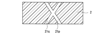
- Two or more through holes 21 may intersect each other in the resin film 2. That is, the resin film 2 may have a set of through holes 21 that intersect with each other in the film 2. At this time, the level of coexistence of breathability and waterproofness as the waterproof breathable membrane 1 is particularly high. Such an example is shown in FIG. In the example shown in FIG. 6, the through holes 21 p and 21 q intersect each other in the resin film 2.
- the resin film 2 may have through holes 23 extending in a direction perpendicular to the main surface of the film in addition to the through holes 21.
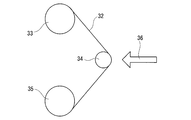
- the resin film 2 shown in FIGS. 3 to 7 can be formed, for example, by controlling the irradiation direction of the ion beam, the irradiation timing, and the shape of the beam line cross section with respect to the original film.
- the belt-shaped original film 32 is fed out from the feed roll 33 and passed through an irradiation roll 34 having a predetermined curvature, and has a predetermined cross-sectional shape and cross-sectional area while passing through the roll 34.
- the ion beam 36 is irradiated by a beam line, and the irradiated original film 32 is wound on a winding roll 35.
- the angle at which the ion film collides with the main surface of the original film 32 while the original film 32 moves on the irradiation roll 34 (incident).
- the angle ⁇ 1) changes. If this is chemically etched, for example, a resin film 2 as shown in FIG. 7 is formed.
- corresponds to the left-right direction of FIG.
- the direction in which the through holes 21 and 23 extend in the resin film 2 (in the waterproof gas-permeable membrane 1) can be confirmed by, for example, observing the main surface and cross section of the film with a scanning electron microscope (SEM).
- SEM scanning electron microscope
- the shape of the opening of the through holes 21 and 23 is not particularly limited. For example, it may be circular or irregular.
- the diameter (opening diameter) of the through holes 21 and 23 is 15 ⁇ m or less. If the diameters of the through holes 21 and 23 are larger than this, the waterproof property as the waterproof breathable membrane 1 is lowered, and it is difficult to achieve both the breathability and the waterproof property.
- the minimum of the diameter of the through-holes 21 and 23 is not specifically limited, For example, it is 0.01 micrometer. When the diameters of the through holes 21 and 23 are excessively small, the air permeability as the waterproof gas-permeable membrane 1 is lowered, and it is difficult to achieve both the air permeability and the water resistance.
- the diameters of the through holes 21 and 23 are the diameters of the circles when the cross-sectional shape (for example, opening shape) of the through holes 21 and 23 is regarded as a circle. Since the through hole 21 extends in a direction inclined with respect to the direction perpendicular to the main surface of the resin film 2, the opening shape thereof is typically an ellipse. However, the cross-sectional shape of the through-hole 21 in the resin film 2 (cross-sectional shape cut perpendicular to the extending direction) can be regarded as a circle like the through-hole 23, and the diameter of this circle is an opening shape. Equal to the minimum diameter of the ellipse. For this reason, about the through-hole 21, the said minimum diameter can be made into the diameter of a through-hole.
- the diameters of the through holes 21 and 23 do not need to be the same in all the through holes 21 and 23 existing in the resin film 2, but in an effective portion of the resin film 2 (a portion that can be used as the waterproof breathable membrane 1). It is preferable that the values agree with a level that can be regarded as substantially the same value (for example, the standard deviation is 10% or less of the average value).
- the diameters of the through holes 21 and 23 can be adjusted by the time for etching the original film and / or the concentration of the etching treatment liquid.
- the diameters of all the through holes 21 and 23 existing in the effective portion of the resin film 2 can be the same.
- the waterproof gas-permeable membrane 1 is 0.01 cm 3 / (cm 2 ⁇ sec) or more and 100 cm 3 / (cm 2 ⁇ ) in terms of the number of fragiles measured in accordance with JIS L1096 (hereinafter simply referred to as “fragile number”). It is preferable to have an air permeability equal to or less than (second) in the thickness direction. Considering that the liquid repellent layer 3 does not substantially affect the air permeability, the resin film 2 has a Frazier number of 0.01 cm 3 / (cm 2 ⁇ sec) or more and 100 cm 3 / (cm 2 ⁇ sec).
- the air permeability is expressed in terms of the number of fragile, and is preferably 2.0 cm 3 / (cm 2 ⁇ sec) or more and 50 cm 3 / (cm 2 ⁇ sec) or less, and 11 cm 3 / (cm 2 ⁇ sec) or more and 50 cm 3 / (cm 2 ⁇ sec) or less is more preferable.
- the porosity of the resin film 2 is preferably 50% or less, preferably 25% or more and 45% or less, and more preferably 30% or more and 40% or less. At this time, the level of coexistence of breathability and waterproofness as the waterproof breathable membrane 1 becomes higher. Further, a stretched porous membrane having a dispersed structure of innumerable pores generated by stretching cannot be a waterproof breathable membrane having such a low porosity.
- the resin film 2 is a non-porous film in which a plurality of through-holes penetrating in the thickness direction are formed, the porosity is open on the main surface with respect to the area of the main surface of the resin film 2. This is the total ratio of the opening areas of the through holes 21 and 23.
- the density (hole density) of the through holes 21 and 23 in the resin film 2 is 1 ⁇ 10 3 pieces / cm 2 or more and 1 ⁇ 10 9 pieces / cm 2 or less.
- the air permeability of the waterproof gas-permeable membrane 1 is lowered. If the pore density exceeds this range, the waterproof property of the waterproof breathable membrane 1 is lowered.
- Pore density, 1 ⁇ 10 5 / cm 2 or more 5 ⁇ 10 8 / cm 2 or less being more preferred.
- the pore density does not need to be constant throughout the resin film 2, but in the effective portion of the resin film 2, it may be constant so that the maximum pore density is not more than 1.5 times the minimum pore density. preferable.
- the pore density can be adjusted by the ion irradiation amount when the original film is irradiated with the ion beam.
- the thickness of the resin film 2 is, for example, 10 ⁇ m or more and 100 ⁇ m or less, and preferably 15 ⁇ m or more and 50 ⁇ m or less.
- the material constituting the resin film 2 is not limited as long as the material can form the through holes 21 in the original film which is a non-porous resin film.
- the resin film 2 is made of, for example, an alkaline solution, an acidic solution, or a resin that decomposes with an alkaline solution or an acidic solution to which at least one selected from an oxidizing agent, an organic solvent, and a surfactant is added. In this case, formation of the through hole 21 in the original film by ion beam irradiation and etching becomes easier.
- the resin film 2 is made of, for example, a resin that can be etched by hydrolysis or oxidative decomposition.
- the resin film 2 can be made of a resin that can be etched with an alkaline solution or an oxidant solution.
- Resin film 2 is made of, for example, at least one resin selected from polyethylene terephthalate (PET), polycarbonate, polyimide, polyethylene naphthalate, and polyvinylidene fluoride.
- PET polyethylene terephthalate
- polycarbonate polycarbonate
- polyimide polyimide
- polyethylene naphthalate polyvinylidene fluoride
- an etching treatment liquid corresponding to the material constituting the resin film 2 is selected.
- the etching treatment liquid is, for example, an alkaline solution, an acidic solution, or an alkaline solution or an acidic solution to which at least one selected from an oxidizing agent, an organic solvent, and a surfactant is added.
- the etching treatment liquid may be an alkaline solution and an oxidant solution.
- the alkaline solution is, for example, a solution containing potassium hydroxide and / or sodium hydroxide as a main component, and may further contain an oxidizing agent.
- the oxidant solution is, for example, a solution containing at least one selected from chlorous acid, chlorite, hypochlorous acid, hypochlorite, hydrogen peroxide, and potassium permanganate as a main component.
- the resin constituting the original film can be oxidatively decomposed.
- An example of a combination of the resin film 2 and the resin constituting the original film and the etching treatment liquid is an alkaline solution (for example, a solution containing sodium hydroxide as a main component) for PET, polycarbonate, and polyethylene naphthalate.
- an oxidizing agent solution for example, a solution containing sodium hypochlorite as a main component for vinylidene chloride.
- a commercially available film can be used as the resin film 2 having the through holes 21.
- Commercially available films are sold as membrane filters, for example, by Oxyphen and Millipore.
- the waterproof breathable membrane 1 may have two or more layers of resin films 2.
- Such a waterproof gas-permeable membrane 1 can be formed by, for example, ion beam irradiation and etching on a laminate having two or more original films.
- the liquid repellent layer 3 is a layer having water repellency, and preferably also has oil repellency.
- the liquid repellent layer 3 has an opening 31 at a position corresponding to the through hole 21 of the resin film 2.
- the opening 31 can also be provided at a position corresponding to the through hole 23.
- the liquid repellent layer 3 is formed on the main surface of the resin film 2.
- the liquid repellent layer 3 only needs to be formed on at least one main surface of the resin film 2.
- Such a liquid repellent layer 3 can be formed, for example, by thinly applying a treatment liquid prepared by diluting a water repellent or a hydrophobic oil repellent with a diluent onto the resin film 2 and drying it.
- the water repellent and the hydrophobic oil repellent are, for example, perfluoroalkyl acrylate and perfluoroalkyl methacrylate.
- the thickness of the liquid repellent layer 3 is preferably less than 1 ⁇ 2 of the diameter of the through hole 21 (and 23).
- the inner peripheral surface of the through hole is also continuous with the liquid repellent layer 3 depending on the diameter of the through hole 21 (and 23). It is possible to coat with a liquid repellent layer (this is the case in the example shown in FIG. 1). In this case, the diameter of the through hole 21 (and 23) is smaller than the original diameter depending on the thickness of the liquid repellent layer.
- the waterproof breathable membrane 1 may include any member other than the resin film 2 and the liquid repellent layer 3 as long as the effects of the present invention can be obtained.
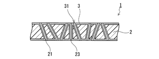
- the member is, for example, a breathable support layer 4 shown in FIG.
- the air-permeable support layer 4 is disposed on one main surface of the resin film 2 of the waterproof gas-permeable membrane 1 shown in FIG.
- the air-permeable support layer 4 is a layer having a higher air permeability in the thickness direction than the resin film 2.
- a woven fabric, a nonwoven fabric, a net, or a mesh can be used.
- the material constituting the air-permeable support layer 4 is, for example, polyester, polyethylene, or aramid resin.
- the liquid repellent layer 3 may or may not be formed on the main surface of the resin film 2 on which the air-permeable support layer 4 is disposed.
- the shape of the air-permeable support layer 4 may be the same as or different from the shape of the resin film 2.
- the breathable support layer 4 has a shape that is arranged only at the peripheral edge of the resin film 2 (specifically, when the resin film is circular, it is a ring-shaped support layer 4 that is arranged only at the peripheral edge). sell.
- the air-permeable support layer 4 is disposed, for example, by a technique such as thermal welding with the resin film 2 or adhesion with an adhesive.
- the air-permeable support layer 4 may be disposed on one main surface of the resin film 2 or may be disposed on both main surfaces.
- the waterproof breathable membrane 1 preferably has a water pressure resistance of 2 kPa or more measured according to the provisions of the water resistance test method B (high water pressure method) of JIS L1092.
- the water pressure resistance of 2 kPa means drip-proof and rain-proof in daily life.
- the water pressure resistance can be 5 kPa or more, or 10 kPa or more.
- the water pressure resistance of 10 kPa means that it can withstand the water pressure at a depth of 1 m.
- waterproofing equivalent to “water protection class 7 (IPX7)” defined in JIS C0920 is secured. For example, even if a device equivalent to IPX7 is accidentally dropped into water, it can be prevented from entering the device within a predetermined depth and time.
- IPX4 water protection class 4
- JIS C0920 water protection class 4
- IPX4 is also one of the waterproof properties required for electronic devices in recent years.
- the waterproof pressure of the waterproof gas-permeable membrane 1 is 5 kPa or more or 10 kPa or more
- both waterproof properties equivalent to IPX4 or IPX7 and air permeability can be achieved.
- a device with a high degree of design freedom including design is realized, such as miniaturization and / or thinning.
- Surface density of the waterproof breathable membrane 1, from the viewpoint of the strength and handling properties of the film preferably from 5 ⁇ 100g / m 2, more preferably 10 ⁇ 50g / m 2.
- the thickness of the waterproof breathable membrane 1 is, for example, 10 to 100 ⁇ m, and preferably 15 to 50 ⁇ m.
- the waterproof breathable membrane 1 may be subjected to a coloring treatment.
- the color of the waterproof gas-permeable membrane 1 that has not been colored is, for example, transparent or white.
- the membrane 1 may stand out.
- the conspicuous membrane stimulates the user's curiosity, and the function as a waterproof breathable membrane may be impaired by piercing with a needle or the like.
- the waterproof gas-permeable membrane 1 is colored, for example, by using the membrane 1 having the same color or a color similar to the color of the housing, the user's attention can be relatively suppressed.
- a colored waterproof breathable membrane may be required due to the design of the housing, and such a design requirement can be met by the coloring process.
- the coloring treatment can be performed by, for example, dyeing the resin film 2 or adding a colorant to the resin film 2.
- the coloring treatment may be performed so that light included in a wavelength range of 380 nm to 500 nm is absorbed.
- the waterproof gas-permeable membrane 1 may be subjected to a coloring treatment that absorbs light included in a wavelength range of 380 nm to 500 nm.
- the resin film 2 includes a colorant having an ability to absorb light included in a wavelength range of 380 nm to 500 nm, or absorbs light included in a wavelength range of 380 nm to 500 nm. It is dyed by a dye having ability.
- the waterproof gas-permeable membrane 1 can be colored blue, gray, brown, pink, green, yellow, or the like.
- the waterproof air-permeable membrane 1 may be colored in black, gray, brown or pink.
- the waterproof breathable membrane of the present invention can be used for the same applications as conventional waterproof breathable membranes.
- the waterproof breathable membrane 1 of the present invention accommodates an acoustic part such as a microphone, a speaker, and a transducer, and a casing provided with an opening for transmitting sound between the acoustic part and the outside, and closes the opening.
- an acoustic part such as a microphone, a speaker, and a transducer
- a casing provided with an opening for transmitting sound between the acoustic part and the outside, and closes the opening.
- it can be used as a waterproof sound-permeable membrane that transmits sound between the acoustic part and the outside and prevents water from entering the casing through the opening from the outside.
- the waterproof sound-permeable membrane (waterproof sound-permeable membrane of the present invention) includes a non-porous resin film 2 in which a plurality of through-holes 21 penetrating in the thickness direction are formed, and a main part of the resin film 2. And a liquid repellent layer 3 having openings 31 at positions corresponding to the plurality of through holes 21, the through holes 21 extending linearly and having a diameter (opening diameter) of 15 ⁇ m or less.
- the hole density of the through holes 21 in the resin film 2 is 1 ⁇ 10 3 pieces / cm 2 or more and 1 ⁇ 10 9 pieces / cm 2 or less, and the resin film 2 is the main film 2 of the film 2.
- the waterproof sound-permeable membrane includes the through-holes 21 extending in a direction inclined with respect to a direction perpendicular to the surface, and the through-holes 21 having different directions extending in an inclined manner are mixed in the resin film 2.
- Through holes 21 having different directions extending at an angle are mixed in the resin film 2, the diameter of the through holes existing in the resin film 2 is 15 ⁇ m or less, and the hole density of the through holes in the resin film 2 is 1 ⁇ 10 3 pieces / cm 3.
- the liquid-repellent layer 3 on the main surface of the resin film 2 while being 2 or more and 1 ⁇ 10 9 pieces / cm 2 or less, a waterproof sound-permeable membrane having excellent waterproof properties and sound-transmitting properties is obtained.
- the said effect as a waterproof sound-permeable membrane does not necessarily originate in the effect as a waterproof breathable membrane, ie, the coexistence (balance) in the level higher than the conventional air permeability and waterproofness.
- the effect as a waterproof sound-permeable membrane is derived from the structure of the film, particularly the structure of the resin film 2.
- the film including the resin film 2 and the liquid repellent layer 3 having the above-described structure can be used as a waterproof gas permeable film or a waterproof sound permeable film, and each achieves the predetermined effect described above. That is.
- the resin film 2 and the liquid repellent layer 3 included in the waterproof sound-permeable membrane of the present invention can have the same configuration as the resin film 2 and the liquid repellent layer 3 included in the waterproof air-permeable membrane 1 described above. Its main effect is the realization of higher waterproofness and sound transmission characteristics. However, considering the fact that it is a sound-permeable membrane, it is more preferable to satisfy the following characteristics.
- the upper limit of the diameter (opening diameter) of the through holes 21 and 23 is preferably 12 ⁇ m or less.
- the diameters of the through holes 21 and 23 are preferably 4.5 ⁇ m or more and 12 ⁇ m or less, and more preferably 5 ⁇ m or more and 11 ⁇ m or less. In this range, the sound transmission characteristics are further improved.
- the waterproof sound-permeable membrane is indicated by the above-mentioned fragile number, preferably 5.0 cm 3 / (cm 2 ⁇ sec) or more and 50 cm 3 / (cm 2 ⁇ sec) or less, more preferably 11 cm 3 / (cm 2 ⁇ sec). It is preferable to have an air permeability in the thickness direction of 50 cm 3 / (cm 2 ⁇ sec) or less. In this range, the sound transmission characteristics are further improved.
- the waterproof sound-permeable membrane of the present invention has high sound-permeable characteristics. High sound transmission characteristics are, for example, reduced “chattering noise”. If the chatter sound is generated more strongly, for example, the sound quality of the sound and music emitted from the speaker, and the sound quality of the sound and music received by the microphone will deteriorate, and the performance, function and appeal of the product as a product will decrease. . According to the waterproof sound-permeable membrane of the present invention, for example, generation of chatter noise due to the placement of the waterproof sound-permeable membrane is suppressed while providing high waterproofness to the opening for transmitting sound to / from the acoustic unit, and The performance, function, and appeal of the product as an electronic device equipped with a sound membrane can be improved.
- the chatter sound of the sound-permeable membrane can be evaluated as follows.
- the chatter sound is generated by inducing a sound having a frequency higher than the frequency of the sound, more specifically, a sound having a frequency range of 5 kHz to 20 kHz. If the generation of the induced sound in such a high sound range is suppressed, the generation of chatter noise due to the arrangement of the waterproof sound-permeable membrane is suppressed.
- the waterproof sound-permeable membrane of the present invention has, for example, an input sound having a waveform of a sine wave and maintaining the sound pressure level so that the sound pressure level of the sound having a frequency of 1 kHz after passing through the membrane is 94 dB, Starting from 100 Hz, when the frequency is continuously increased at a rate of 100 Hz / second and input to the membrane having an effective area of 132.7 mm 2 , the input sound is input until 20 seconds elapse from the start of input.
- FFT Fast Fourier Transform
- the sound pressure level of the input sound is adjusted at a frequency of 1 kHz because the sound having a frequency of 1 kHz corresponds to a standard human voice and can be heard most sharply in the audible range. Based on something.
- the input sound whose sound pressure level has been adjusted in this way is input to the waterproof sound-permeable membrane while continuously changing the frequency, and is transmitted through the membrane, and FFT analysis is performed on the transmitted sound.
- the membrane having an effective area of 132.7 mm 2 is assumed to be a waterproof sound-permeable membrane having a circular effective portion having a radius of 6.5 mm.
- the effective area is the part where sound is actually input to the membrane when the waterproof sound-permeable membrane is placed so as to block the opening of the housing, and the sound is output from the membrane through the membrane (effective For example, it does not include the area of the support or adhesive portion that is disposed and formed on the peripheral edge of the membrane in order to dispose the waterproof sound-permeable membrane.
- the effective area is typically the area of the opening in which the membrane is arranged or the area of the opening in the waterproof sound-permeable member in which the support is arranged at the periphery of the waterproof sound-permeable membrane. It is possible.
- the integrated sound pressure level is a value obtained by integrating the sound pressure levels of sounds within the specific frequency range in the frequency direction, and is a general acoustic analysis (evaluation) apparatus or acoustic analysis that performs FFT analysis of the sound. (Evaluation) Can be obtained by software.
- the ratio A / B is preferably 1.16 or more, more preferably 1.25 or more. As the ratio A / B is larger, the waterproof sound-permeable membrane is suppressed from generating chatter noise.
- the waterproof sound-permeable membrane of the present invention further has an input sound having a waveform of a sine wave and maintaining the sound pressure level so that the sound pressure level of the sound having a frequency of 1 kHz after passing through the membrane is 94 dB, Starting from 100 Hz, when the frequency is continuously increased at a rate of 100 Hz / second and input to the membrane having an effective area of 132.7 mm 2 , the input sound is input until 20 seconds elapse.
- the sound transmitted through the membrane may be a waterproof sound-permeable membrane in which a sound pressure level of 40 dB or more is observed in a sound region of a frequency of 5 kHz or more and 20 kHz or less, and the frequency range of the input sound is 1.3 kHz or less.
- the transmitted sound includes a component belonging to the sound range of the frequency of 5 kHz or more and 20 kHz or less and having a sound pressure level of 40 dB or more. Will occur.
- the frequency of the input sound is further increased, the above components are not included in the transmitted sound at another frequency (maximum frequency F max ).
- the difference ⁇ F between F max and F min is 1.3 kHz or less, a waterproof sound-permeable membrane with less chatter noise is obtained.
- the maximum value of F max is 2 kHz 20 seconds after the start of input.
- ⁇ F is preferably 1.3 kHz or less, and more preferably 1.1 kHz or less.
- the waterproof sound-permeable membrane of the present invention further has an input sound having a waveform of a sine wave and maintaining the sound pressure level so that the sound pressure level of the sound having a frequency of 1 kHz after passing through the membrane is 94 dB, Starting from 100 Hz, when the frequency is continuously increased at a rate of 100 Hz / second and input to the membrane having an effective area of 132.7 mm 2 , the input sound is input until 20 seconds elapse.
- the sound transmitted through the membrane may be a waterproof sound-permeable membrane in which a sound pressure level of 40 dB or higher is observed in a frequency range of 5 kHz to 20 kHz, and the maximum frequency F max of the input sound is 1.5 kHz or lower.
- the F max is preferably 1.5 kHz or less, and more preferably 1.1 kHz or less.
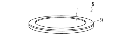
- the waterproof ventilation member 5 shown in FIG. 10 is a waterproof ventilation membrane 1 having a circular shape when viewed from a direction perpendicular to the main surface of the membrane, and a support body that is a ring-shaped sheet joined to the peripheral edge of the membrane 1. 51.
- the form in which the support body 51 is joined to the waterproof gas-permeable membrane 1 reinforces the waterproof gas-permeable membrane 1 and improves its handleability.
- the support body 51 becomes an allowance to the part to which the waterproof ventilation member 5 is arrange
- the shape of the support 51 is not limited. For example, as shown in FIG. 11, even if it is the support body 51 which is a frame-shaped sheet
- membrane is a rectangle. Good. As shown in FIGS. 10 and 11, by reducing the shape of the support 51 to the shape of the periphery of the waterproof gas-permeable membrane 1, a decrease in the air permeability of the waterproof gas-permeable membrane 1 due to the arrangement of the support 51 is suppressed. Moreover, the sheet-like support body 51 is preferable from the viewpoints of the handleability of the waterproof ventilation member 5 and the disposition property to the housing, particularly the disposition property within the housing. In the example shown in FIGS. 10 and 11, the waterproof gas-permeable membrane 1 is exposed except for the peripheral portion where the support body 51 is disposed (both surfaces of the waterproof gas-permeable membrane 1 are exposed).
- the material constituting the support 51 is, for example, a resin, a metal, or a composite material thereof.
- the resin is, for example, a polyolefin such as polyethylene or polypropylene; a polyester such as PET or polycarbonate; a polyimide or a composite material thereof.
- the metal is a metal having excellent corrosion resistance, such as stainless steel or aluminum.
- the thickness of the support 51 is, for example, 5 to 500 ⁇ m, and preferably 25 to 200 ⁇ m.
- the ring width (frame width: difference between the outer shape and the inner diameter) is suitably about 0.5 to 2 mm.
- a foam made of the above resin may be used.
- the joining method of the waterproof breathable membrane 1 and the support 51 is not particularly limited, and for example, methods such as heat welding, ultrasonic welding, adhesion with an adhesive, and adhesion with a double-sided tape can be employed.
- the waterproof ventilation member 5 may include two or more waterproof ventilation membranes 1 and / or two or more supports 51.
- the waterproof ventilation member of the present invention can be used for the same applications as conventional waterproof ventilation members. Moreover, the waterproof ventilation member of this invention can be used as a waterproof sound-permeable member by using the waterproof ventilation film with which the said member is provided as a waterproof sound-permeable membrane. At this time, the waterproof sound-permeable member includes the waterproof breathable membrane (sound-permeable membrane) of the present invention and a support joined to the waterproof breathable membrane (sound-permeable membrane). The configuration of the support can be the same as the configuration of the support 51 of the waterproof ventilation member.
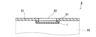
- FIG. 12 An example of the waterproof ventilation structure of the present invention is shown in FIG.
- the waterproof ventilation structure 8 shown in FIG. 12 includes a casing 81 provided with an opening 82 for allowing gas to pass between the inside 83 and the outside, and a waterproof ventilation film 1 arranged so as to close the opening (opening) 82.
- the opening 82 is a space that connects the inside and the outside of the housing 81, and gas can travel between the inside and the outside of the housing 81 through the opening.
- the waterproof breathable membrane 1 can prevent water from entering the housing 81 from the outside through the opening 82 while allowing gas to pass between the outside and the inside 83 of the housing 81.
- the waterproof gas-permeable membrane 1 is bonded to the housing 81 via the support body 51.
- a waterproof ventilation member including the waterproof ventilation membrane 1 and the support 51 is joined to the housing 81.
- the waterproof gas-permeable membrane 1 is joined to the housing 81 from the inside 83 of the housing 81, but may be joined from the outside of the housing 81.
- the housing 81 is made of resin, metal, glass, and a composite material thereof.
- the support 51 may be a double-sided tape.
- the parts, devices, equipment, products, etc. having the waterproof ventilation structure 8 are not limited.
- the waterproof ventilation structure of the present invention can be applied to various uses as with the conventional waterproof ventilation structure.
- the waterproof ventilation structure of this invention can be used as a waterproof sound-permeable structure by using the waterproof ventilation film with which the said structure is provided as a waterproof sound-permeable film.
- this waterproof sound transmission structure transmits sound between a housing provided with an opening for transmitting sound between the inside and the outside, and the inside and the outside arranged so as to close the opening.
- a waterproof sound-permeable membrane that prevents water from entering the inside through the opening, and the waterproof sound-permeable membrane is the waterproof breathable membrane (sound-permeable membrane) of the present invention.
- the structure of the housing and the bonding of the waterproof sound-permeable membrane to the housing can be the same as the waterproof ventilation structure.
- an example of applying the waterproof ventilation structure of the present invention as a waterproof sound transmission structure is an electronic device. More specifically, the electronic device includes a housing in which an acoustic unit is accommodated and an opening for transmitting sound between the acoustic unit and the outside, and the acoustic unit disposed so as to close the opening.
- a waterproof sound-permeable membrane that transmits sound between the portion and the outside and prevents water from entering the housing from the outside through the opening, and the waterproof sound-permeable membrane is waterproof according to the present invention. It is a gas permeable membrane (sound permeable membrane).
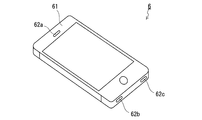
- FIG. 13A An example of an electronic device is shown in FIG. 13A.
- the electronic device illustrated in FIG. 13A is a smartphone that is a type of mobile phone.
- the housing 61 of the smartphone 6 includes an opening 62a provided in the vicinity of a transducer that is a kind of sound generation part and sound receiving part, and an opening 62b provided in the vicinity of a microphone that is a kind of sound receiving part, And an opening 62c provided in the vicinity of a speaker which is a kind of sound generation unit. Sound is transmitted between the outside of the smartphone 6 and each acoustic part (transducer, microphone, and speaker) accommodated in the housing 61 via the openings 62a to 62c. As shown in FIG.
- a waterproof gas-permeable membrane (sound-permeable membrane) 1 is attached to the housing 61 from the inside so as to close these openings 62a to 62c.
- the location and method of disposing the waterproof gas-permeable membrane (sound-permeable membrane) 1 in the electronic device 6 are not limited as long as the opening (opening) provided in the housing 61 of the device 6 is closed by the membrane.
- the waterproof gas-permeable membrane (sound-permeable membrane) 1 is joined to the housing 61 via the support 51 (that is, as a waterproof gas-permeable member (sound-permeable member)).
- a technique such as sticking using a double-sided tape, thermal welding, high-frequency welding, or ultrasonic welding can be employed.
- the support 51 may be a double-sided tape.
- the housing 61 is made of resin, metal, glass, and a composite material thereof.
- the display unit of the electronic device 6 may constitute a part of the housing 61 like a smartphone and a tablet computer.
- the electronic device is not limited to the smartphone 6.
- the housing is provided with an opening for transmitting sound between the outside and the sound section, and it is necessary to prevent water from entering through the opening. This applies to all types of electronic devices in which the film 1 can be disposed so as to close the opening.
- the electronic device is, for example, a mobile phone such as a feature phone and a smartphone, a tablet computer, a wearable computer, a PDA, a game device, a mobile computer such as a notebook computer, an electronic notebook, a digital camera, a video camera, and an electronic book reader.
- an electronic device having a waterproof ventilation structure may be used for the purpose of simply ensuring ventilation and waterproofing without considering sound transmission.
- This electronic device is arranged so as to block the opening and a housing having an opening, and allows water to enter the inside through the opening while allowing gas to pass between the inside and the outside of the housing. With waterproof breathable membrane to prevent.
- This waterproof gas-permeable membrane is the waterproof gas-permeable membrane of the present invention.
- this electronic device case is an electronic device case that houses an electronic device having an acoustic part, and is provided with an opening for transmitting sound between the acoustic part of the electronic device and the outside, A waterproof sound-permeable membrane disposed so as to close the opening and transmitting sound between the acoustic part of the electronic device and the outside and preventing water from entering the case from the outside through the opening
- the waterproof sound-permeable membrane is the waterproof breathable membrane (sound-permeable membrane) of the present invention.
- FIG. 14A An example of an electronic device case is shown in FIG. 14A.
- the case 7 shown in FIG. 14A is provided with openings 71 a to 71 c for transmitting sound between the acoustic part of the electronic device housed in the case 7 and the outside of the case 7.
- the case 7 shown in FIG. 14A is a case of a smartphone different from the smartphone 6 shown in FIG. 13A, and the opening 71a transmits sound from the receiving part of the smartphone.
- the openings 71c are provided to transmit the sound from the speaker of the smartphone to the outside. As shown in FIG.
- the case 7 further includes a waterproof gas-permeable membrane (sound-permeable membrane) 1 disposed so as to close the openings 71a (71b, 71c). Sound is transmitted between the sound part of the electronic device housed in the inside 72 of the case 7 and the outside by the film, and the inside 72 of the case 7 through the openings 71a (71b, 71c), and thus the outside. Water can be prevented from entering the electronic equipment.
- a waterproof gas-permeable membrane (sound-permeable membrane) 1 disposed so as to close the openings 71a (71b, 71c). Sound is transmitted between the sound part of the electronic device housed in the inside 72 of the case 7 and the outside by the film, and the inside 72 of the case 7 through the openings 71a (71b, 71c), and thus the outside. Water can be prevented from entering the electronic equipment.
- the method of disposing the waterproof gas-permeable membrane (sound-permeable membrane) 1 in the electronic device case 7 is not limited as long as the openings (openings) 71a (71b, 71c) are blocked by the membrane 1.
- the waterproof gas-permeable membrane (sound-permeable membrane) 1 is joined from the inside 72 to the case 7 via the support body 51 (that is, as a waterproof gas-permeable member (sound-permeable member)).
- a technique such as sticking using a double-sided tape, thermal welding, high-frequency welding, ultrasonic welding, or the like can be employed.
- the support 51 may be a double-sided tape. It is also possible to dispose a waterproof gas-permeable membrane (sound-permeable membrane) 1 from the outside of the case 7.
- the electronic device case 7 is made of resin, metal, glass and a composite material thereof.
- the electronic device case 7 can have any configuration as long as the effects of the present invention can be obtained.
- the case 7 shown in FIG. 14A is a case for a smartphone, and includes a film 73 that can operate a touch panel of a smartphone accommodated therein from the outside.
- a case for an electronic device having a waterproof ventilation structure may be used for the purpose of simply ensuring ventilation and waterproofing without considering sound transmission.
- This case for an electronic device has an opening, is arranged so as to close the opening, and allows water to enter inside through the opening while allowing gas to pass between the inside and outside of the case. With waterproof breathable membrane to prevent.
- This waterproof gas-permeable membrane is the waterproof gas-permeable membrane of the present invention.
- the air permeability in the thickness direction of the waterproof air-permeable membrane was determined in accordance with the provisions of JIS L1096 (Breathability measurement method A: Frazier method).
- the water pressure resistance of the waterproof breathable membrane was determined in accordance with the provisions of the water resistance test method B (high water pressure method) of JIS L1092. However, since the membrane is significantly deformed in the area of the test piece indicated in this regulation, a stainless steel mesh (opening diameter 2 mm) is placed on the opposite side of the pressure surface of the membrane, and measurement is performed with the membrane deformed to some extent. did.
- the hole density of the resin film was determined by observing both main surfaces of the resin film with SEM, counting the number of through holes in the obtained SEM image, and dividing this by the unit area.
- the oil repellency of the waterproof breathable membrane was evaluated as follows. Place the waterproof breathable membrane and copy paper (plain paper) on top of each other so that the waterproof breathable membrane is on top and the copy paper is on the bottom, drop a drop of castor oil on the waterproof breathable membrane with a dropper, and leave for 1 minute did. Thereafter, the waterproof breathable film was removed, and the state of the copy paper was confirmed. When the copy paper was wet with castor oil, the waterproof breathable film was not oil-repellent, and when it was not wet, the oil-repellent was given.
- Example 1 A non-porous commercially available PET film (it4ip, Track etched membrane, thickness 44 ⁇ m) in which a plurality of through holes penetrating in the thickness direction was formed was prepared.
- This film is a film produced by irradiating a non-porous PET film with an ion beam and chemically etching the irradiated film.
- the through hole was a straight hole having a diameter of 6.5 ⁇ m, and (2) the through hole extending in a direction inclined with respect to the main surface of the film.
- through-holes extending in a direction perpendicular to the main surface are mixed in the film, and (3) all through-holes extending in a direction inclined with respect to the main surface of the film are in the extending direction. Is in a direction forming an angle ⁇ 1 of 30 ° or less with respect to a direction perpendicular to the main surface, and (4) one direction as viewed from a direction perpendicular to the main surface of the film as a through hole extending in a tilted direction And a group extending in the direction opposite to the direction (a group having an angle ⁇ 2 of 180 °) are mixed, and (5) there are a plurality of sets of through holes intersecting in the film. confirmed.
- the hole density of the film was 1.8 ⁇ 10 6 holes / cm 2 .
- the liquid repellent treatment solution was prepared by diluting a liquid repellent (X-70-029C, manufactured by Shin-Etsu Chemical Co., Ltd.) with a diluent (manufactured by Shin-Etsu Chemical Co., Ltd., FS thinner) to a concentration of 0.7% by weight.
- the waterproof breathable membrane thus obtained had an air permeability (fragile) of 18.5 cm 3 / (cm 2 ⁇ sec), a water pressure resistance of 15 kPa, and an oil repellency of “Yes”.
- a non-porous commercially available PET film (it4ip, Track etched membrane, thickness 44 ⁇ m) in which a plurality of through holes penetrating in the thickness direction was formed was prepared.
- This film is a film produced by irradiating a non-porous PET film with an ion beam and chemically etching the irradiated film.
- the through hole was a straight hole having a diameter of 6.5 ⁇ m
- (2) the through hole extending in a direction perpendicular to the main surface of the film It was confirmed that only was present in the film.
- the hole density of the film was 1.8 ⁇ 10 6 holes / cm 2 , the same as in the example.
- the liquid repellent treatment solution was prepared by diluting a liquid repellent (X-70-029C, manufactured by Shin-Etsu Chemical Co., Ltd.) with a diluent (manufactured by Shin-Etsu Chemical Co., Ltd., FS thinner) to a concentration of 0.7% by weight.
- the waterproof breathable membrane thus obtained had an air permeability (fragile) of 17.1 cm 3 / (cm 2 ⁇ sec), a water pressure resistance of 9 kPa, and an oil repellency of “Yes”.
- Example 1 In comparison with Comparative Example 1, in Example 1, both the breathability and the water pressure resistance of the waterproof breathable membrane were improved.
- Example 2 A non-porous commercially available PET film (it4ip, Track etched membrane, thickness 44 ⁇ m) in which a plurality of through holes penetrating in the thickness direction was formed was prepared.
- This film is a film produced by irradiating a non-porous PET film with an ion beam and chemically etching the irradiated film.
- the through hole was a straight hole having a diameter of 5.5 ⁇ m, and (2) the through hole extending in a direction inclined with respect to the main surface of the film.
- through-holes extending in a direction perpendicular to the main surface are mixed in the film, and (3) all through-holes extending in a direction inclined with respect to the main surface of the film are in the extending direction. Is in a direction forming an angle ⁇ 1 of 30 ° or less with respect to a direction perpendicular to the main surface, and (4) one direction as viewed from a direction perpendicular to the main surface of the film as a through hole extending in a tilted direction And a group extending in the direction opposite to the direction (a group having an angle ⁇ 2 of 180 °) are mixed, and (5) there are a plurality of sets of through holes intersecting in the film. confirmed.
- the hole density of the film was 1.8 ⁇ 10 6 holes / cm 2 .
- the liquid repellent treatment solution was prepared by diluting a liquid repellent (X-70-029C, manufactured by Shin-Etsu Chemical Co., Ltd.) with a diluent (manufactured by Shin-Etsu Chemical Co., Ltd., FS thinner) to a concentration of 0.7% by weight.
- the waterproof breathable membrane thus obtained had an air permeability (Fragile) of 8.0 cm 3 / (cm 2 ⁇ sec), a water pressure resistance of 18 kPa, and an oil repellency of “Yes”.
- a non-porous commercially available PET film (it4ip, Track etched membrane, thickness 44 ⁇ m) in which a plurality of through holes penetrating in the thickness direction was formed was prepared.
- This film is a film produced by irradiating a non-porous PET film with an ion beam and chemically etching the irradiated film.
- the through hole was a straight hole having a diameter of 5.5 ⁇ m
- the hole density of the film was 1.8 ⁇ 10 6 holes / cm 2 , the same as in the example.
- the liquid repellent treatment solution was prepared by diluting a liquid repellent (X-70-029C, manufactured by Shin-Etsu Chemical Co., Ltd.) with a diluent (manufactured by Shin-Etsu Chemical Co., Ltd., FS thinner) to a concentration of 0.7% by weight.
- the waterproof breathable membrane thus obtained had an air permeability (fragile) of 5.0 cm 3 / (cm 2 ⁇ sec), a water pressure resistance of 11 kPa, and an oil repellency of “Yes”.
- Example 2 Compared with Comparative Example 2, in Example 2, both the breathability of the waterproof breathable membrane and the water pressure resistance were improved.
- Example 3 A non-porous commercially available PET film (it4ip, Track etched membrane, thickness 44 ⁇ m) in which a plurality of through holes penetrating in the thickness direction was formed was prepared.
- This film is a film produced by irradiating a non-porous PET film with an ion beam and chemically etching the irradiated film.
- the through hole was a straight hole having a diameter of 5.9 ⁇ m, and (2) the through hole extending in a direction inclined with respect to the main surface of the film.
- through-holes extending in a direction perpendicular to the main surface are mixed in the film, and (3) all through-holes extending in a direction inclined with respect to the main surface of the film are in the extending direction. Is in a direction forming an angle ⁇ 1 of 30 ° or less with respect to a direction perpendicular to the main surface, and (4) one direction as viewed from a direction perpendicular to the main surface of the film as a through hole extending in a tilted direction And a group extending in the direction opposite to the direction (a group having an angle ⁇ 2 of 180 °) are mixed, and (5) there are a plurality of sets of through holes intersecting in the film. confirmed.
- the hole density of the film was 2.0 ⁇ 10 6 holes / cm 2 .
- the liquid repellent treatment solution was prepared by diluting a liquid repellent (X-70-029C, manufactured by Shin-Etsu Chemical Co., Ltd.) with a diluent (manufactured by Shin-Etsu Chemical Co., Ltd., FS thinner) to a concentration of 0.7% by weight.
- the waterproof breathable membrane thus obtained had an air permeability (fragile) of 25.0 cm 3 / (cm 2 ⁇ sec), a water pressure resistance of 17 kPa, and an oil repellency of “Yes”.
- a non-porous commercially available PET film (it4ip, Track etched membrane, thickness 44 ⁇ m) in which a plurality of through holes penetrating in the thickness direction was formed was prepared.
- This film is a film produced by irradiating a non-porous PET film with an ion beam and chemically etching the irradiated film.
- the through hole was a straight hole having a diameter of 5.9 ⁇ m
- the hole density of the film was 2.0 ⁇ 10 6 holes / cm 2 , the same as in the example.
- the liquid repellent treatment solution was prepared by diluting a liquid repellent (X-70-029C, manufactured by Shin-Etsu Chemical Co., Ltd.) with a diluent (manufactured by Shin-Etsu Chemical Co., Ltd., FS thinner) to a concentration of 0.7% by weight.
- the waterproof breathable membrane thus obtained had an air permeability (fragile) of 14.5 cm 3 / (cm 2 ⁇ sec), a water pressure resistance of 10 kPa, and an oil repellency of “Yes”.
- Example 4 A non-porous commercially available PET film (it4ip, Track etched membrane, thickness 44 ⁇ m) in which a plurality of through holes penetrating in the thickness direction was formed was prepared.
- This film is a film produced by irradiating a non-porous PET film with an ion beam and chemically etching the irradiated film.
- the through hole was a straight hole having a diameter of 10.0 ⁇ m, and (2) the through hole extending in a direction inclined with respect to the main surface of the film.
- through-holes extending in a direction perpendicular to the main surface are mixed in the film, and (3) all through-holes extending in a direction inclined with respect to the main surface of the film are in the extending direction. Is in a direction forming an angle ⁇ 1 of 30 ° or less with respect to a direction perpendicular to the main surface, and (4) one direction as viewed from a direction perpendicular to the main surface of the film as a through hole extending in a tilted direction And a group extending in the direction opposite to the direction (a group having an angle ⁇ 2 of 180 °) are mixed, and (5) there are a plurality of sets of through holes intersecting in the film. confirmed.
- the hole density of the film was 5.0 ⁇ 10 5 holes / cm 2 .
- the liquid repellent treatment solution was prepared by diluting a liquid repellent (X-70-029C, manufactured by Shin-Etsu Chemical Co., Ltd.) with a diluent (manufactured by Shin-Etsu Chemical Co., Ltd., FS thinner) to a concentration of 0.7% by weight.
- the waterproof breathable membrane thus obtained had an air permeability (fragile) of 50.0 cm 3 / (cm 2 ⁇ sec), a water pressure resistance of 6 kPa, and an oil repellency of “Yes”.
- a simulated case 91 (made of polystyrene, outer dimensions 60 mm ⁇ 50 mm ⁇ 28 mm) imitating the case of a mobile phone was prepared.
- the simulated housing 91 is provided with a speaker mounting hole 92 (circular with a diameter of 13 mm) serving as an opening for transmitting the sound output from the speaker to the outside of the housing, and a conducting port 93 of the speaker cable 96. There is no opening other than that.
- double-sided tape manufactured by Nitto Denko, No.5620A, thickness 0.2 mm
- the waterproof gas-permeable membrane 1 waterproof sound-permeable membrane
- Examples 2 to 4 and Comparative Example 2 was punched into a circle having a diameter of 16 mm.
- the support 51, the waterproof gas-permeable membrane 1 and the support 51 were laminated in this order with the same outer shape, and a sample for evaluating sound transmission characteristics was obtained.
- the effective area of the sound-permeable membrane in this sample was 132.7 mm 2 (corresponding to the area of a circle with a diameter of 13 mm).
- each prepared sample was attached to the inside of the speaker mounting hole 92 of the simulated casing 91 as shown in FIG. 15 by using one support body (double-sided tape) 51.
- the effective portion of the sound-permeable membrane of the sample was made to coincide with the opening of the speaker mounting hole 92.
- a speaker 95 (Star Precision, SCG-16A, 16 mm outer shape circle) was further attached.
- the external shape of the sample was matched with the external shape of the speaker.
- the speaker cable 96 of the speaker 95 is led out of the casing 91 from the conduction port 93, and then the conduction hole 93 is closed with putty.
- the speaker cable 96 and the microphone 97 (Bruel & Kjaer Sound & Vibration Measurement A / S (B & K), Type 2669) are connected to the sound evaluation device (B & K, Multi-analyzer System 3560-B-030).
- the microphone 97 is disposed at a position 50 mm away from the front surface of the speaker 95 housed in the simulated housing 91.
- FFT analysis test signal 100 Hz to 20 kHz, sweep
- the sound passing characteristics sound pressure level, integrated sound pressure level
- the sound pressure level of the sound output from the speaker 95 (the sound input to the sample) is 94 dB as the sound pressure level of the sound having a frequency of 1 kHz after passing through the sample. It adjusted so that it might become.
- the sound input to the sample was a sine wave, and the frequency was continuously increased at a rate of 100 Hz / second starting from a frequency of 100 Hz.
- the sound pressure level and the integrated sound pressure level of the sound transmitted through the sample and received by the microphone 97 can be automatically obtained by the sound evaluation apparatus over an arbitrary measurement time range. In the present example, the sound passing characteristics of the sample were evaluated such that the sound pressure level of the sound and the integrated sound pressure level were obtained over a range from the start of measurement to 20 seconds.
- FIG. 16A shows the measurement result of the sample using the waterproof gas-permeable membrane (waterproof sound-permeable membrane) produced in Example 2.
- the horizontal axis of FIG. 16A is the frequency (Hz; logarithmic axis) of the sound received by the speaker, and the vertical axis is the elapsed time (seconds) from the start of measurement.
- the sound pressure level of the sound received by the speaker is represented by the difference in color of the plot shown in FIG. 16A before being expressed in white and black as in the drawing of the present application, that is, in the original state.
- the relationship between the sound pressure level value and the color is shown on the right side of FIG. 16A.
- FIG. 16A a plurality of curved plots are displayed.
- the leftmost plot corresponds to the sound (fundamental wave) that is input to the sample from the speaker, passes through the membrane as it is, and is received by the microphone. ing.
- the plot is curved because the horizontal axis is a logarithmic axis.
- the plurality of plots seen on the right side of the fundamental wave correspond to a sound having a higher frequency than the fundamental wave that is generated while the fundamental wave passes through the membrane.
- the sound (input wave) input to the sample changes only to 2 kHz within 20 seconds after starting from 100 Hz, but measurement is started even in the high frequency range of 5 kHz to 20 kHz, which is considered to correlate with the occurrence of chattering sound. It can be seen from FIG. 16A that sound has been detected for approximately 5-12 seconds.
- the ratio A between the integrated sound pressure level A in the sound range of frequencies from 100 Hz to 20 kHz and the integrated sound pressure level B in the sound range of frequencies from 5 kHz to 20 kHz obtained from this FFT analysis / B was 1.28.
- the cumulative sound pressure level B decreases, that is, the ratio A / B increases, when the sound is less generated in the frequency range of 5 kHz to 20 kHz. For this reason, when the ratio A / B is large, the generation of chatter noise when sound passes through the waterproof sound-permeable membrane is small, that is, the waterproof sound-permeable membrane generates less chatter sound.
- a sound pressure level of 40 dB or higher is observed in a sound range of 5 kHz to 20 kHz, and the frequency range of the input wave is 0.7 kHz (minimum frequency 500 Hz, maximum frequency 1 0.2 kHz).
- FIG. 16B shows the measurement results of the sample using the waterproof gas-permeable membrane (waterproof sound-permeable membrane) produced in Comparative Example 2.
- FIG. 16B and subsequent FIGS. 16C and D are diagrams showing measurement results in the same manner as FIG. 16A.
- the frequency of the input wave to the sample changes only up to 2 kHz in 20 seconds after starting from 100 Hz, but even in the sound range of 5 kHz to 20 kHz, which is considered to correlate with the generation of chattering sound. Sound was detected for approximately 2-16 seconds from the start of measurement.
- the ratio A between the integrated sound pressure level A in the sound range of frequencies from 100 Hz to 20 kHz and the integrated sound pressure level B in the sound range of frequencies from 5 kHz to 20 kHz obtained from this FFT analysis / B was 1.15.
- a sound pressure level of 40 dB or higher is observed in the sound range of 5 kHz to 20 kHz, and the frequency range of the input wave is 1.4 kHz (minimum frequency 200 Hz, maximum frequency 1 .6 kHz).
- FIG. 16C shows the measurement result of the sample using the waterproof gas-permeable membrane (waterproof sound-permeable membrane) produced in Example 3.
- the frequency of the input wave to the sample changes only up to 2 kHz in 20 seconds after starting from 100 Hz, but also in a frequency range of 5 kHz to 20 kHz, which is considered to correlate with the occurrence of chatter noise. Sound was detected for approximately 6-11 seconds from the start of measurement.
- the ratio A between the integrated sound pressure level A in the sound range of frequency 100 Hz to 20 kHz and the integrated sound pressure level B in the sound frequency range of 5 kHz to 20 kHz obtained from this FFT analysis. / B was 1.41. Further, in the sample using the film of Example 3, a sound pressure level of 40 dB or higher is observed in the sound range of the frequency of 5 kHz to 20 kHz.
- the frequency range of the input wave is 0.5 kHz (minimum frequency 600 Hz, maximum frequency 1 0.1 kHz).
- FIG. 16D shows the measurement results of the sample using the waterproof gas-permeable membrane (waterproof sound-permeable membrane) produced in Example 4.
- the frequency of the input wave to the sample changes only up to 2 kHz in 20 seconds after starting from 100 Hz, but even in the sound range of 5 kHz to 20 kHz, which is considered to correlate with the generation of chattering sound. Sound was detected for approximately 8-10 seconds from the start of measurement.
- the ratio A between the integrated sound pressure level A in the sound range of frequency 100 Hz to 20 kHz and the integrated sound pressure level B in the sound frequency range of 5 kHz to 20 kHz obtained from this FFT analysis. / B was 1.89.
- a sound pressure level of 40 dB or higher is observed in a sound range of 5 kHz to 20 kHz, and the frequency range of the input wave is 0.2 kHz (minimum frequency 800 Hz, maximum frequency 1 0.0 kHz).
- a non-porous resin film in which a plurality of through holes penetrating in the thickness direction are formed; A liquid repellent layer having openings at positions corresponding to the plurality of through-holes formed on the main surface of the resin film, The through hole extends linearly and has a diameter of 15 ⁇ m or less, The hole density of the through holes in the resin film is 1 ⁇ 10 3 pieces / cm 2 or more and 1 ⁇ 10 9 pieces / cm 2 or less, The resin film has the through-hole extending in a direction inclined with respect to a direction perpendicular to the main surface of the film, and the resin film includes the through-holes having different directions extending in an inclined manner. Breathable membrane. 2.
- the waterproof breathable membrane according to item 1 wherein an angle formed by the inclined and extending direction with respect to the vertical direction is 45 ° or less. 3.
- the waterproof breathable membrane according to any one of items 1 to 4 wherein the resin film has the through-holes that intersect with each other in the film. 6). Item 6.
- Item 12 The waterproof breathable membrane according to any one of items 1 to 11, which is colored black, gray, brown or pink.
- 14 The waterproof breathable membrane according to any one of items 1 to 13, further comprising a breathable support material laminated on the resin film.
- a waterproof ventilation member comprising: a support joined to the waterproof ventilation membrane. 16.
- An electronic device case that houses an electronic device, Has an opening,
- the waterproof breathable membrane is disposed so as to close the opening, and prevents gas from entering from the outside through the opening while allowing gas to pass between the inside and the outside of the case, 15.
- a case for electronic equipment, wherein the waterproof gas permeable membrane is the waterproof gas permeable membrane according to any one of items 1 to 14. 19.
- the through hole extends linearly and has a diameter of 15 ⁇ m or less,
- the hole density of the through holes in the resin film is 1 ⁇ 10 3 pieces / cm 2 or more and 1 ⁇ 10 9 pieces / cm 2 or less,
- the resin film has the through-hole extending in a direction inclined with respect to a direction perpendicular to the main surface of the film, and the resin film includes the through-holes having different directions extending in an inclined manner. Sound-permeable membrane.
- the waterproof sound-permeable membrane according to Item 19 wherein an angle formed by the inclined and extending direction with respect to the vertical direction is 45 ° or less.
- Item 20 The waterproof sound-permeable membrane according to Item 19, wherein an angle formed by the inclined and extending direction with respect to the vertical direction is 30 ° or less.
- 22 Item 19-21, wherein the resin film has a set of through-holes extending from the main surface in different directions at an angle of 90 ° or more when viewed from a direction perpendicular to the main surface of the film.
- Item 32. The waterproof sound-permeable membrane according to any one of Items 19 to 31, further comprising a breathable support member laminated on the resin film.
- Item 33 The waterproof sound-permeable membrane according to any one of Items 19 to 32, An input sound having a sine wave waveform and maintaining a sound pressure level such that the sound pressure level of a sound having a frequency of 1 kHz after passing through the film is 94 dB starts from 100 Hz at a rate of 100 Hz / second.
- the integrated sound pressure level A in the frequency range of 100 Hz to 20 kHz, and the frequency of 5 kHz to 20 kHz, obtained by FFT analysis for the sound that has passed through the membrane until 20 seconds have passed since the start of input of the input sound.
- Item 34. The waterproof sound-permeable membrane according to any one of Items 19 to 33, An input sound having a sine wave waveform and maintaining a sound pressure level such that the sound pressure level of a sound having a frequency of 1 kHz after passing through the film is 94 dB starts from 100 Hz at a rate of 100 Hz / second.
- a sound pressure level of 40 dB or more is observed in a sound range of a frequency of 5 kHz or more and 20 kHz or less with respect to a sound that has passed through the membrane until 20 seconds have passed after the input sound is input, and the frequency range of the input sound is 1
- a waterproof sound-permeable membrane that is 3 kHz or less. 35. 36.
- the waterproof sound-permeable membrane according to any one of items 19 to 34, An input sound having a sine wave waveform and maintaining a sound pressure level such that the sound pressure level of a sound having a frequency of 1 kHz after passing through the film is 94 dB starts from 100 Hz at a rate of 100 Hz / second.
- a sound pressure level of 40 dB or higher is observed in a sound range of 5 kHz or more and 20 kHz or less with respect to the sound that has passed through the membrane until 20 seconds have passed after the input of the input sound is started.
- the maximum frequency of the input sound is 1.
- a waterproof sound-permeable membrane that is 5 kHz or less. 36.
- a housing provided with an opening for transmitting sound between the inside and the outside; A waterproof sound-permeable membrane disposed so as to close the opening, and transmitting sound between the inside and the outside and preventing water from entering the inside through the opening from the outside, A waterproof sound-permeable structure, wherein the waterproof sound-permeable film is the waterproof sound-permeable film according to any one of Items 19 to 35.
- a housing in which an acoustic unit is accommodated and an opening for transmitting sound between the acoustic unit and the outside is provided;
- a waterproof sound-permeable membrane disposed so as to close the opening and transmitting sound between the acoustic unit and the outside and preventing water from entering the housing from the outside through the opening;
- the electronic device, wherein the waterproof sound-permeable membrane is the waterproof sound-permeable membrane according to any one of Items 19 to 35. 39.
- the waterproof breathable membrane of the present invention can be used for the same applications as conventional waterproof breathable membranes.
- the waterproof sound-permeable membrane of the present invention can be used for the same applications as conventional waterproof sound-permeable membranes.
Landscapes
- Chemical & Material Sciences (AREA)
- Engineering & Computer Science (AREA)
- Chemical Kinetics & Catalysis (AREA)
- Physics & Mathematics (AREA)
- Signal Processing (AREA)
- Acoustics & Sound (AREA)
- Manufacturing & Machinery (AREA)
- Optics & Photonics (AREA)
- Microelectronics & Electronic Packaging (AREA)
- Inorganic Chemistry (AREA)
- Laminated Bodies (AREA)
- Separation Using Semi-Permeable Membranes (AREA)
- Details Of Audible-Bandwidth Transducers (AREA)
- Casings For Electric Apparatus (AREA)
- Manufacture Of Porous Articles, And Recovery And Treatment Of Waste Products (AREA)
Abstract
Description
図1に、本発明の防水通気膜の一例を示す。図1に示す防水通気膜1は、非多孔質の樹脂フィルム2と、樹脂フィルム2の主面上に形成された撥液層3とを備える。樹脂フィルム2には、厚さ方向に貫通する複数の貫通孔21(21a~21g)が形成されている。撥液層3は、貫通孔21に対応する位置(樹脂フィルム2における貫通孔21の開口に対応する位置)に開口31を有する。樹脂フィルム2は、その厚さ方向に通気可能である経路を貫通孔21以外に有さない非多孔質の樹脂フィルムであり、典型的には、当該貫通孔21を除いて無孔の(中実の)樹脂フィルムである。貫通孔21は、樹脂フィルム2の双方の主面に開口を有する。
本発明の防水通気膜1は、マイクロフォン、スピーカーおよびトランスデューサーのような音響部が収容され、当該音響部と外部との間で音を伝達する開口が設けられた筐体と、当該開口を塞ぐように配置された、音響部と外部との間で音を伝達するとともに外部から当該開口を介して筐体内に水が浸入することを防ぐ防水通音膜としても使用できる。このとき、この防水通音膜(本発明の防水通音膜)は、厚さ方向に貫通する複数の貫通孔21が形成された、非多孔質の樹脂フィルム2と、前記樹脂フィルム2の主面上に形成された、前記複数の貫通孔21と対応する位置に開口31を有する撥液層3と、を備え、前記貫通孔21は、直線状に延びるとともに15μm以下の径(開口径)を有し、前記樹脂フィルム2における前記貫通孔21の孔密度は、1×10³個/cm2以上1×109個/cm2以下であり、前記樹脂フィルム2は、当該フィルム2の主面に垂直な方向に対して傾いた方向に延びる前記貫通孔21を有し、当該傾いて延びる方向が異なる前記貫通孔21が前記樹脂フィルム2に混在している、防水通音膜である。
本発明の防水通気部材の一例を、図10に示す。図10に示す防水通気部材5は、膜の主面に垂直な方向から見た形状が円形である防水通気膜1と、当該膜1の周縁部に接合されたリング状のシートである支持体51とを備える。防水通気膜1に支持体51が接合された形態により、防水通気膜1が補強されるとともに、その取扱性が向上する。また、支持体51が、筐体の開口など、防水通気部材5が配置される部分への取り付けしろとなるため、防水通気膜1の取り付け作業が容易となる。
本発明の防水通気構造の一例を図12に示す。図12に示す防水通気構造8は、内部83と外部との間で気体を通過させる開口82が設けられた筐体81と、開口(開口部)82を塞ぐように配置された防水通気膜1とを備える。開口82は筐体81の内部と外部とをつなぐ空間であり、当該開口を通じて、気体が筐体81の内部と外部とを行き来できる。そして、防水通気膜1により、筐体81の外部と内部83との間で気体を透過させながら、外部から開口82を介して筐体81内に水が浸入することを防ぐことができる。図12に示す例では、支持体51を介して防水通気膜1が筐体81に接合されている。換言すれば、防水通気膜1と支持体51とを備える防水通気部材が筐体81に接合されている。また、図12に示す例では、筐体81の内部83から防水通気膜1が筐体81に接合されているが、筐体81の外部から接合されていてもよい。
樹脂フィルムの双方の主面を走査型電子顕微鏡(SEM)により観察し、得られたSEM像から任意に選択した10の貫通孔の最小径を各々当該像から求め、その平均値を樹脂フィルムの貫通孔の径とした。
防水通気膜の厚さ方向の通気度は、JIS L1096の規定(通気性測定A法:フラジール形法)に準拠して求めた。
防水通気膜の耐水圧は、JIS L1092の耐水度試験B法(高水圧法)の規定に準拠して求めた。ただし、この規定に示された試験片の面積では膜が著しく変形するため、ステンレスメッシュ(開口径2mm)を膜の加圧面の反対側に設置し、当該膜の変形をある程度抑制した状態で測定した。
樹脂フィルムの孔密度は、樹脂フィルムの双方の主面をSEMにより観察し、得られたSEM像にある貫通孔の数を目視にて数え、これを単位面積で除して求めた。
防水通気膜の撥油性は、以下のように評価した。防水通気膜とコピー用紙(普通紙)とを、防水通気膜が上、コピー用紙が下になるように重ねて置き、スポイトを用いて防水通気膜にひまし油を1滴垂らした後、1分間放置した。その後、防水通気膜を取り除いてコピー用紙の状態を確認し、コピー用紙がひまし油で濡れている場合を防水通気膜の撥油性なし、濡れていない場合を撥油性有りとした。
厚さ方向に貫通する複数の貫通孔が形成された非多孔質の市販のPETフィルム(it4ip製、Track etched membrane、厚さ44μm)を準備した。このフィルムは、無孔のPETフィルムにイオンビームを照射し、照射後のフィルムを化学エッチングして製造されたフィルムである。このフィルムの表面および断面をSEMにより観察したところ、(1)貫通孔が、6.5μmの径を有するストレート孔であること、(2)フィルムの主面に対して傾いた方向に延びる貫通孔と、当該主面に対して垂直な方向に延びる貫通孔とがフィルム内に混在していること、(3)フィルムの主面に対して傾いた方向に延びる貫通孔は、全て、その延びる方向が当該主面に垂直な方向に対して30°以下の角度θ1を成す方向にあること、(4)傾いた方向に延びる貫通孔として、フィルムの主面に垂直な方向から見てある一方向に延びる群と、当該方向とは反対側に延びる群(角度θ2が180°である群)とが混在していること、(5)フィルム内で交差する貫通孔の組が複数あること、が確認された。フィルムの孔密度は、1.8×10⁶個/cm2であった。
厚さ方向に貫通する複数の貫通孔が形成された非多孔質の市販のPETフィルム(it4ip製、Track etched membrane、厚さ44μm)を準備した。このフィルムは、無孔のPETフィルムにイオンビームを照射し、照射後のフィルムを化学エッチングして製造されたフィルムである。このフィルムの表面および断面をSEMにより観察したところ、(1)貫通孔が、6.5μmの径を有するストレート孔であること、(2)フィルムの主面に対して垂直な方向に延びる貫通孔のみがフィルム内に存在していること、が確認された。フィルムの孔密度は、実施例と同じ1.8×10⁶個/cm2であった。
厚さ方向に貫通する複数の貫通孔が形成された非多孔質の市販のPETフィルム(it4ip製、Track etched membrane、厚さ44μm)を準備した。このフィルムは、無孔のPETフィルムにイオンビームを照射し、照射後のフィルムを化学エッチングして製造されたフィルムである。このフィルムの表面および断面をSEMにより観察したところ、(1)貫通孔が、5.5μmの径を有するストレート孔であること、(2)フィルムの主面に対して傾いた方向に延びる貫通孔と、当該主面に対して垂直な方向に延びる貫通孔とがフィルム内に混在していること、(3)フィルムの主面に対して傾いた方向に延びる貫通孔は、全て、その延びる方向が当該主面に垂直な方向に対して30°以下の角度θ1を成す方向にあること、(4)傾いた方向に延びる貫通孔として、フィルムの主面に垂直な方向から見てある一方向に延びる群と、当該方向とは反対側に延びる群(角度θ2が180°である群)とが混在していること、(5)フィルム内で交差する貫通孔の組が複数あること、が確認された。フィルムの孔密度は、1.8×10⁶個/cm2であった。
厚さ方向に貫通する複数の貫通孔が形成された非多孔質の市販のPETフィルム(it4ip製、Track etched membrane、厚さ44μm)を準備した。このフィルムは、無孔のPETフィルムにイオンビームを照射し、照射後のフィルムを化学エッチングして製造されたフィルムである。このフィルムの表面および断面をSEMにより観察したところ、(1)貫通孔が、5.5μmの径を有するストレート孔であること、(2)フィルムの主面に対して垂直な方向に延びる貫通孔のみがフィルム内に存在していること、が確認された。フィルムの孔密度は、実施例と同じ1.8×10⁶個/cm2であった。
厚さ方向に貫通する複数の貫通孔が形成された非多孔質の市販のPETフィルム(it4ip製、Track etched membrane、厚さ44μm)を準備した。このフィルムは、無孔のPETフィルムにイオンビームを照射し、照射後のフィルムを化学エッチングして製造されたフィルムである。このフィルムの表面および断面をSEMにより観察したところ、(1)貫通孔が、5.9μmの径を有するストレート孔であること、(2)フィルムの主面に対して傾いた方向に延びる貫通孔と、当該主面に対して垂直な方向に延びる貫通孔とがフィルム内に混在していること、(3)フィルムの主面に対して傾いた方向に延びる貫通孔は、全て、その延びる方向が当該主面に垂直な方向に対して30°以下の角度θ1を成す方向にあること、(4)傾いた方向に延びる貫通孔として、フィルムの主面に垂直な方向から見てある一方向に延びる群と、当該方向とは反対側に延びる群(角度θ2が180°である群)とが混在していること、(5)フィルム内で交差する貫通孔の組が複数あること、が確認された。フィルムの孔密度は、2.0×10⁶個/cm2であった。
厚さ方向に貫通する複数の貫通孔が形成された非多孔質の市販のPETフィルム(it4ip製、Track etched membrane、厚さ44μm)を準備した。このフィルムは、無孔のPETフィルムにイオンビームを照射し、照射後のフィルムを化学エッチングして製造されたフィルムである。このフィルムの表面および断面をSEMにより観察したところ、(1)貫通孔が、5.9μmの径を有するストレート孔であること、(2)フィルムの主面に対して垂直な方向に延びる貫通孔のみがフィルム内に存在していること、が確認された。フィルムの孔密度は、実施例と同じ2.0×10⁶個/cm2であった。
厚さ方向に貫通する複数の貫通孔が形成された非多孔質の市販のPETフィルム(it4ip製、Track etched membrane、厚さ44μm)を準備した。このフィルムは、無孔のPETフィルムにイオンビームを照射し、照射後のフィルムを化学エッチングして製造されたフィルムである。このフィルムの表面および断面をSEMにより観察したところ、(1)貫通孔が、10.0μmの径を有するストレート孔であること、(2)フィルムの主面に対して傾いた方向に延びる貫通孔と、当該主面に対して垂直な方向に延びる貫通孔とがフィルム内に混在していること、(3)フィルムの主面に対して傾いた方向に延びる貫通孔は、全て、その延びる方向が当該主面に垂直な方向に対して30°以下の角度θ1を成す方向にあること、(4)傾いた方向に延びる貫通孔として、フィルムの主面に垂直な方向から見てある一方向に延びる群と、当該方向とは反対側に延びる群(角度θ2が180°である群)とが混在していること、(5)フィルム内で交差する貫通孔の組が複数あること、が確認された。フィルムの孔密度は、5.0×10⁵個/cm2であった。
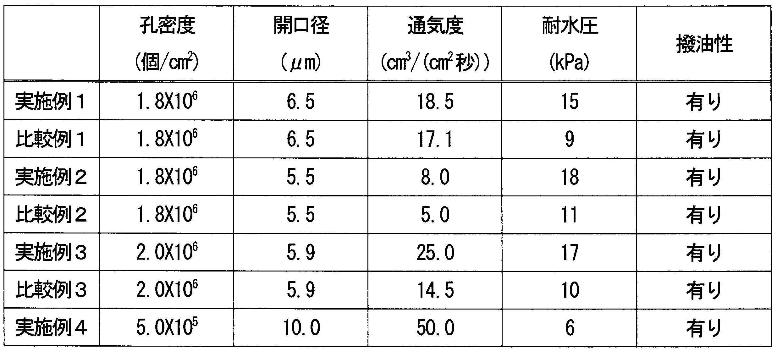

前記樹脂フィルムの主面上に形成された、前記複数の貫通孔と対応する位置に開口を有する撥液層と、を備え、
前記貫通孔は、直線状に延びるとともに15μm以下の径を有し、
前記樹脂フィルムにおける前記貫通孔の孔密度は、1×10³個/cm2以上1×109個/cm2以下であり、
前記樹脂フィルムは、当該フィルムの主面に垂直な方向に対して傾いた方向に延びる前記貫通孔を有し、当該傾いて延びる方向が異なる前記貫通孔が前記樹脂フィルムに混在している、防水通気膜。
2.前記垂直な方向に対して前記傾いて延びる方向が成す角度が45°以下である、項目1に記載の防水通気膜。
3.前記垂直な方向に対して前記傾いて延びる方向が成す角度が30°以下である、項目1に記載の防水通気膜。
4.前記樹脂フィルムが、当該フィルムの主面に垂直な方向から見たときに90°以上の角度を成して当該主面から互いに異なる方向に延びる前記貫通孔の組を有する、項目1~3のいずれかに記載の防水通気膜。
5.前記樹脂フィルムが、当該フィルム内で互いに交差する前記貫通孔を有する、項目1~4のいずれかに記載の防水通気膜。
6.前記樹脂フィルムが、当該フィルムの主面に垂直な方向に延びる前記貫通孔をさらに有する、項目1~5のいずれかに記載の防水通気膜。
7.気孔率が50%以下である、項目1~6のいずれかに記載の防水通気膜。
8.JIS L1096の規定に準拠して測定したフラジール数で示して、0.01cm3/(cm2・秒)以上100cm3/(cm2・秒)以下の通気度を厚さ方向に有する、項目1~7のいずれかに記載の防水通気膜。
9.JIS L1092の耐水度試験B法(高水圧法)の規定に準拠して測定した耐水圧が2kPa以上である、項目1~8のいずれかに記載の防水通気膜。
10.前記樹脂フィルムが、アルカリ溶液または酸化剤溶液によってエッチング可能な樹脂から構成される、項目1~9のいずれかに記載の防水通気膜。
11.前記樹脂フィルムが、ポリエチレンテレフタレート、ポリカーボネート、ポリイミド、ポリエチレンナフタレートおよびポリフッ化ビニリデンから選ばれる少なくとも1種の樹脂から構成される、項目1~10のいずれかに記載の防水通気膜。
12.波長380nm以上500nm以下の波長域に含まれる光を吸収する着色処理が施されている、項目1~11のいずれかに記載の防水通気膜。
13.黒色、灰色、茶色または桃色に着色されている、項目1~11のいずれかに記載の防水通気膜。
14.前記樹脂フィルムに積層された通気性支持材をさらに備える、項目1~13のいずれかに記載の防水通気膜。
15.項目1~14のいずれかに記載の防水通気膜と、
前記防水通気膜に接合された支持体と、を備える防水通気部材。
16.開口を有する筐体と、
前記開口を塞ぐように配置され、前記筐体の内部と外部との間で気体を透過させながら外部から前記開口を介して内部に水が浸入することを防ぐ防水通気膜と、を備え、
前記防水通気膜が項目1~14のいずれかに記載の防水通気膜である、防水通気構造。
17.開口を有する筐体と、
前記開口を塞ぐように配置され、前記筐体の内部と外部との間で気体を透過させながら外部から前記開口を介して内部に水が浸入することを防ぐ防水通気膜と、を備え、
前記防水通気膜が項目1~14のいずれかに記載の防水通気膜である、電子機器。
18.電子機器を収容する電子機器用ケースであって、
開口を有し、
前記開口を塞ぐように配置され、前記ケースの内部と外部との間で気体を透過させながら、外部から前記開口を介して内部に水が浸入することを防ぐ防水通気膜を備え、
前記防水通気膜が項目1~14のいずれかに記載の防水通気膜である、電子機器用ケース。
19.厚さ方向に貫通する複数の貫通孔が形成された、非多孔質の樹脂フィルムと、
前記樹脂フィルムの主面上に形成された、前記複数の貫通孔と対応する位置に開口を有する撥液層と、を備え、
前記貫通孔は、直線状に延びるとともに15μm以下の径を有し、
前記樹脂フィルムにおける前記貫通孔の孔密度は、1×10³個/cm2以上1×109個/cm2以下であり、
前記樹脂フィルムは、当該フィルムの主面に垂直な方向に対して傾いた方向に延びる前記貫通孔を有し、当該傾いて延びる方向が異なる前記貫通孔が前記樹脂フィルムに混在している、防水通音膜。
20.前記垂直な方向に対して前記傾いて延びる方向が成す角度が45°以下である、項目19に記載の防水通音膜。
21.前記垂直な方向に対して前記傾いて延びる方向が成す角度が30°以下である、項目19に記載の防水通音膜。
22.前記樹脂フィルムが、当該フィルムの主面に垂直な方向から見たときに90°以上の角度を成して当該主面から互いに異なる方向に延びる前記貫通孔の組を有する、項目19~21のいずれかに記載の防水通音膜。
23.前記樹脂フィルムが、当該フィルム内で互いに交差する前記貫通孔を有する、項目19~22のいずれかに記載の防水通音膜。
24.前記樹脂フィルムが、当該フィルムの主面に垂直な方向に延びる前記貫通孔をさらに有する、項目19~23のいずれかに記載の防水通音膜。
25.気孔率が50%以下である、項目19~24のいずれかに記載の防水通音膜。
26.JIS L1096の規定に準拠して測定したフラジール数で示して、0.01cm3/(cm2・秒)以上100cm3/(cm2・秒)以下の通気度を厚さ方向に有する、項目19~25のいずれかに記載の防水通音膜。
27.JIS L1092の耐水度試験B法(高水圧法)の規定に準拠して測定した耐水圧が2kPa以上である、項目19~26のいずれかに記載の防水通音膜。
28.前記樹脂フィルムが、アルカリ溶液または酸化剤溶液によってエッチング可能な樹脂から構成される、項目19~27のいずれかに記載の防水通音膜。
29.前記樹脂フィルムが、ポリエチレンテレフタレート、ポリカーボネート、ポリイミド、ポリエチレンナフタレートおよびポリフッ化ビニリデンから選ばれる少なくとも1種の樹脂から構成される、項目19~28のいずれかに記載の防水通音膜。
30.波長380nm以上500nm以下の波長域に含まれる光を吸収する着色処理が施されている、項目19~29のいずれかに記載の防水通音膜。
31.黒色、灰色、茶色または桃色に着色されている、項目19~29のいずれかに記載の防水通音膜。
32.前記樹脂フィルムに積層された通気性支持材をさらに備える、項目19~31のいずれかに記載の防水通音膜。
33.項目19~32のいずれかに記載の防水通音膜であって、
サイン波の波形を有し、前記膜を透過した後の周波数1kHzの音の音圧レベルが94dBとなるように音圧レベルを保った入力音を、100Hzから開始して100Hz/秒の速度で周波数を連続的に増加させながら、有効面積132.7mm2の前記膜に入力したときに、
前記入力音の入力開始から20秒経過するまでの間に前記膜を透過した音について、FFT分析により求めた、周波数100Hz以上20kH以下の音域における積算音圧レベルAと、周波数5kHz以上20kHz以下の音域における積算音圧レベルBとの比A/Bが1.16以上である、防水通音膜。
34.項目19~33のいずれかに記載の防水通音膜であって、
サイン波の波形を有し、前記膜を透過した後の周波数1kHzの音の音圧レベルが94dBとなるように音圧レベルを保った入力音を、100Hzから開始して100Hz/秒の速度で周波数を連続的に増加させながら、有効面積132.7mm2の前記膜に入力したときに、
前記入力音の入力開始から20秒経過するまでの間に前記膜を透過した音について周波数5kHz以上20kHz以下の音域で40dB以上の音圧レベルが観測される、前記入力音の周波数の範囲が1.3kHz以下である、防水通音膜。
35.項目19~34のいずれかに記載の防水通音膜であって、
サイン波の波形を有し、前記膜を透過した後の周波数1kHzの音の音圧レベルが94dBとなるように音圧レベルを保った入力音を、100Hzから開始して100Hz/秒の速度で周波数を連続的に増加させながら、有効面積132.7mm2の前記膜に入力したときに、
前記入力音の入力開始から20秒経過するまでの間に前記膜を透過した音について周波数5kHz以上20kHz以下の音域で40dB以上の音圧レベルが観測される、前記入力音の最大周波数が1.5kHz以下である、防水通音膜。
36.項目19~35のいずれかに記載の防水通音膜と、
前記防水通音膜に接合された支持体と、を備える防水通音部材。
37.内部と外部との間で音を伝達する開口が設けられた筐体と、
前記開口を塞ぐように配置された、内部と外部との間で音を伝達するとともに外部から前記開口を介して内部に水が浸入することを防ぐ防水通音膜と、を備え、
前記防水通音膜が項目19~35のいずれかに記載の防水通音膜である、防水通音構造。
38.音響部が収容され、前記音響部と外部との間で音を伝達する開口が設けられた筐体と、
前記開口を塞ぐように配置された、前記音響部と外部との間で音を伝達するとともに外部から前記開口を介して前記筐体内に水が浸入することを防ぐ防水通音膜と、を備え、
前記防水通音膜が項目19~35のいずれかに記載の防水通音膜である、電子機器。
39.音響部を有する電子機器を収容する電子機器用ケースであって、
前記電子機器の音響部と外部との間で音を伝達する開口が設けられ、
前記開口を塞ぐように配置された、前記電子機器の音響部と外部との間で音を伝達するとともに外部から前記開口を介して前記ケース内に水が浸入することを防ぐ防水通音膜を備え、
前記防水通音膜が項目19~35のいずれかに記載の防水通音膜である、電子機器用ケース。
Claims (20)
- 厚さ方向に貫通する複数の貫通孔が形成された、非多孔質の樹脂フィルムと、
前記樹脂フィルムの主面上に形成された、前記複数の貫通孔と対応する位置に開口を有する撥液層と、を備え、
前記貫通孔は、直線状に延びるとともに15μm以下の径を有し、
前記樹脂フィルムにおける前記貫通孔の孔密度は、1×10³個/cm2以上1×109個/cm2以下であり、
前記樹脂フィルムは、当該フィルムの主面に垂直な方向に対して傾いた方向に延びる前記貫通孔を有し、当該傾いて延びる方向が異なる前記貫通孔が前記樹脂フィルムに混在している、防水通気膜。 - 前記垂直な方向に対して前記傾いて延びる方向が成す角度が45°以下である、請求項1に記載の防水通気膜。
- 前記垂直な方向に対して前記傾いて延びる方向が成す角度が30°以下である、請求項1に記載の防水通気膜。
- 前記樹脂フィルムが、当該フィルムの主面に垂直な方向から見たときに90°以上の角度を成して当該主面から互いに異なる方向に延びる前記貫通孔の組を有する、請求項1に記載の防水通気膜。
- 前記樹脂フィルムが、当該フィルム内で互いに交差する前記貫通孔を有する、請求項1に記載の防水通気膜。
- 前記樹脂フィルムが、当該フィルムの主面に垂直な方向に延びる前記貫通孔をさらに有する、請求項1に記載の防水通気膜。
- 気孔率が50%以下である、請求項1に記載の防水通気膜。
- JIS L1096の規定に準拠して測定したフラジール数で示して、0.01cm3/(cm2・秒)以上100cm3/(cm2・秒)以下の通気度を厚さ方向に有する、請求項1に記載の防水通気膜。
- JIS L1092の耐水度試験B法(高水圧法)の規定に準拠して測定した耐水圧が2kPa以上である、請求項1に記載の防水通気膜。
- 前記樹脂フィルムが、アルカリ溶液または酸化剤溶液によってエッチング可能な樹脂から構成される、請求項1に記載の防水通気膜。
- 前記樹脂フィルムが、ポリエチレンテレフタレート、ポリカーボネート、ポリイミド、ポリエチレンナフタレートおよびポリフッ化ビニリデンから選ばれる少なくとも1種の樹脂から構成される、請求項1に記載の防水通気膜。
- 波長380nm以上500nm以下の波長域に含まれる光を吸収する着色処理が施されている、請求項1に記載の防水通気膜。
- 黒色、灰色、茶色または桃色に着色されている、請求項1に記載の防水通気膜。
- 前記樹脂フィルムに積層された通気性支持材をさらに備える、請求項1に記載の防水通気膜。
- 請求項1に記載の防水通気膜と、
前記防水通気膜に接合された支持体と、を備える防水通気部材。 - 開口を有する筐体と、
前記開口を塞ぐように配置され、前記筐体の内部と外部との間で気体を透過させながら外部から前記開口を介して内部に水が浸入することを防ぐ防水通気膜と、を備え、
前記防水通気膜が請求項1に記載の防水通気膜である、防水通気構造。 - 厚さ方向に貫通する複数の貫通孔が形成された、非多孔質の樹脂フィルムと、
前記樹脂フィルムの主面上に形成された、前記複数の貫通孔と対応する位置に開口を有する撥液層と、を備え、
前記貫通孔は、直線状に延びるとともに15μm以下の径を有し、
前記樹脂フィルムにおける前記貫通孔の孔密度は、1×10³個/cm2以上1×109個/cm2以下であり、
前記樹脂フィルムは、当該フィルムの主面に垂直な方向に対して傾いた方向に延びる前記貫通孔を有し、当該傾いて延びる方向が異なる前記貫通孔が前記樹脂フィルムに混在している、防水通音膜。 - 請求項17に記載の防水通音膜であって、
サイン波の波形を有し、前記膜を透過した後の周波数1kHzの音の音圧レベルが94dBとなるように音圧レベルを保った入力音を、100Hzから開始して100Hz/秒の速度で周波数を連続的に増加させながら、有効面積132.7mm2の前記膜に入力したときに、
前記入力音の入力開始から20秒経過するまでの間に前記膜を透過した音について、FFT分析により求めた、周波数100Hz以上20kH以下の音域における積算音圧レベルAと、周波数5kHz以上20kHz以下の音域における積算音圧レベルBとの比A/Bが1.16以上である、防水通音膜。 - 請求項17に記載の防水通音膜であって、
サイン波の波形を有し、前記膜を透過した後の周波数1kHzの音の音圧レベルが94dBとなるように音圧レベルを保った入力音を、100Hzから開始して100Hz/秒の速度で周波数を連続的に増加させながら、有効面積132.7mm2の前記膜に入力したときに、
前記入力音の入力開始から20秒経過するまでの間に前記膜を透過した音について周波数5kHz以上20kHz以下の音域で40dB以上の音圧レベルが観測される、前記入力音の周波数の範囲が1.3kHz以下である、防水通音膜。 - 請求項17に記載の防水通音膜であって、
サイン波の波形を有し、前記膜を透過した後の周波数1kHzの音の音圧レベルが94dBとなるように音圧レベルを保った入力音を、100Hzから開始して100Hz/秒の速度で周波数を連続的に増加させながら、有効面積132.7mm2の前記膜に入力したときに、
前記入力音の入力開始から20秒経過するまでの間に前記膜を透過した音について周波数5kHz以上20kHz以下の音域で40dB以上の音圧レベルが観測される、前記入力音の最大周波数が1.5kHz以下である、防水通音膜。
Priority Applications (4)
| Application Number | Priority Date | Filing Date | Title |
|---|---|---|---|
| EP14839773.0A EP3040193B1 (en) | 2013-08-30 | 2014-08-29 | Waterproof breathable membrane, waterproof breathable element provided with same, waterproof breathable structure and use of the membrane |
| CN201480047883.XA CN105492195B (zh) | 2013-08-30 | 2014-08-29 | 防水透气膜、具备该防水透气膜的防水透气构件和防水透气结构、以及防水透声膜 |
| US14/914,978 US11478760B2 (en) | 2013-08-30 | 2014-08-29 | Waterproof gas-permeable membrane, waterproof gas-permeable member and waterproof gas-permeable structure including same, and waterproof sound-permeable membrane |
| KR1020167007746A KR20160052593A (ko) | 2013-08-30 | 2014-08-29 | 방수 통기막과 그것을 구비하는 방수 통기 부재 및 방수 통기 구조, 그리고 방수 통음막 |
Applications Claiming Priority (4)
| Application Number | Priority Date | Filing Date | Title |
|---|---|---|---|
| JP2013179687 | 2013-08-30 | ||
| JP2013-179687 | 2013-08-30 | ||
| JP2014167787A JP6474977B2 (ja) | 2013-08-30 | 2014-08-20 | 防水通気膜とそれを備える防水通気部材および防水通気構造ならびに防水通音膜 |
| JP2014-167787 | 2014-08-20 |
Publications (1)
| Publication Number | Publication Date |
|---|---|
| WO2015029451A1 true WO2015029451A1 (ja) | 2015-03-05 |
Family
ID=52586039
Family Applications (1)
| Application Number | Title | Priority Date | Filing Date |
|---|---|---|---|
| PCT/JP2014/004452 Ceased WO2015029451A1 (ja) | 2013-08-30 | 2014-08-29 | 防水通気膜とそれを備える防水通気部材および防水通気構造ならびに防水通音膜 |
Country Status (7)
| Country | Link |
|---|---|
| US (1) | US11478760B2 (ja) |
| EP (1) | EP3040193B1 (ja) |
| JP (1) | JP6474977B2 (ja) |
| KR (1) | KR20160052593A (ja) |
| CN (1) | CN105492195B (ja) |
| TW (1) | TWI648993B (ja) |
| WO (1) | WO2015029451A1 (ja) |
Cited By (3)
| Publication number | Priority date | Publication date | Assignee | Title |
|---|---|---|---|---|
| CN106304709A (zh) * | 2015-05-11 | 2017-01-04 | 深圳富泰宏精密工业有限公司 | 疏水结构及其制作方法 |
| CN107149882A (zh) * | 2016-03-02 | 2017-09-12 | 天津工业大学 | 一种聚偏氟乙烯抗污染膜及其制备方法 |
| US10798474B2 (en) | 2016-07-27 | 2020-10-06 | W. L. Gore & Associates, Co., Ltd. | Waterproof sound-transmissive cover, waterproof sound-transmissive cover member and acoustic device |
Families Citing this family (23)
| Publication number | Priority date | Publication date | Assignee | Title |
|---|---|---|---|---|
| CZ304937B6 (cs) * | 2013-11-01 | 2015-01-28 | Příhoda S.R.O. | Vzduchotechnický dílec |
| JP6588828B2 (ja) * | 2014-01-13 | 2019-10-09 | セーレン株式会社 | 通音防水膜およびその製造方法 |
| EP3290466B1 (en) * | 2015-04-30 | 2024-06-05 | Nitto Denko Corporation | Polymer resin film, and air-permeable membrane, sound-permeable membrane, acoustic resistor, air-permeable membrane member, sound-permeable membrane member, acoustic resistor member, and audio device that include the polymer resin film, and method for producing the polymer resin film |
| JP6696832B2 (ja) * | 2015-06-04 | 2020-05-20 | 日東電工株式会社 | マスク |
| US10034073B2 (en) * | 2015-08-04 | 2018-07-24 | Apple Inc. | Device having a composite acoustic membrane |
| JP2017146101A (ja) * | 2016-02-15 | 2017-08-24 | セイコーエプソン株式会社 | 防水部材、防水部材の製造方法、圧力センサーおよび電子モジュール |
| DE112017001147B4 (de) * | 2016-03-04 | 2022-11-24 | Asahi Kasei Kabushiki Kaisha | Modul für Gastrennung, Gastrennungsverfahren und Verwendung des Gastrennungsverfahrens zur Herstellung eines Olefingases |
| US10602254B2 (en) * | 2016-06-13 | 2020-03-24 | Current Lighting Solutions, Llc | Packaging of luminaire mounted microphones |
| KR101896367B1 (ko) | 2016-07-08 | 2018-10-24 | 주식회사 아모그린텍 | 방수 통기 시트 |
| CN107318059A (zh) * | 2017-08-02 | 2017-11-03 | 苏州孝义家精密金属有限公司 | 一种超薄防水透声复合模组 |
| CN108284656A (zh) * | 2018-01-25 | 2018-07-17 | 江苏科德宝建筑节能科技有限公司 | 一种抗压强度高的防水透气复合膜 |
| JP7112268B2 (ja) * | 2018-07-03 | 2022-08-03 | シャープ株式会社 | 空気極の製造方法、及び金属空気電池の製造方法 |
| KR102155248B1 (ko) * | 2018-07-18 | 2020-09-11 | 대상 주식회사 | 가스 배출용 패킹시트 및 이를 포함하는 식품 용기 |
| JP2021030100A (ja) * | 2019-08-15 | 2021-03-01 | 新科實業有限公司SAE Magnetics(H.K.)Ltd. | 薄膜フィルタ、薄膜フィルタ基板、薄膜フィルタの製造方法および薄膜フィルタ基板の製造方法並びにmemsマイクロフォンおよびmemsマイクロフォンの製造方法 |
| CN110360360B (zh) * | 2019-08-21 | 2021-03-12 | 哈尔滨新中新电子股份有限公司 | 一种防水透气条及其组成的水控机 |
| US11439959B2 (en) * | 2020-04-07 | 2022-09-13 | Global Life Sciences Solutions Usa, Llc | Porous flat deformation-resistant membrane |
| CN111912759A (zh) * | 2020-07-15 | 2020-11-10 | 天津日博工业技术有限公司 | 一种防水透气膜的透气量测试方法 |
| CN112929798B (zh) * | 2021-01-29 | 2022-11-01 | 杭州安普鲁薄膜科技有限公司 | 一种防水透声膜组件及其装有防水透声膜组件的mems |
| EP4520204A3 (en) * | 2021-03-19 | 2025-06-18 | Philip Morris Products S.A. | Aerosol-generating device with venting means |
| CN113304627A (zh) * | 2021-05-29 | 2021-08-27 | 杭州安普鲁薄膜科技有限公司 | 一种超疏水的防水膜组件 |
| CN114979434A (zh) * | 2022-05-12 | 2022-08-30 | Oppo广东移动通信有限公司 | 摄像头模组及电子设备 |
| CN115278477B (zh) * | 2022-06-30 | 2025-05-23 | 歌尔股份有限公司 | 用于发声装置的球顶、振膜组件、发声装置及电子设备 |
| CN119639046B (zh) * | 2024-12-27 | 2026-01-09 | 广东顶峰精密技术有限公司 | 一种防水透气膜的制备方法及防水透气膜 |
Citations (15)
| Publication number | Priority date | Publication date | Assignee | Title |
|---|---|---|---|---|
| JPS6237556U (ja) * | 1985-08-26 | 1987-03-05 | ||
| JPS63154750A (ja) * | 1986-11-20 | 1988-06-28 | コミツサリア タ レネルジー アトミーク | 微小孔薄膜の製造方法と微小孔薄膜 |
| JPS6399503U (ja) * | 1986-12-19 | 1988-06-28 | ||
| JPH04228716A (ja) * | 1990-09-12 | 1992-08-18 | Hitachi Cable Ltd | 透気性遮水シ―ト及びそれを用いた遮水工法 |
| JPH05295145A (ja) * | 1990-06-01 | 1993-11-09 | Cyclopore Sa | 透明な微小孔あき材料およびその製造方法 |
| JPH0827561A (ja) * | 1994-07-13 | 1996-01-30 | Nitto Denko Corp | 無機質微孔膜とその製法 |
| JP2000201388A (ja) * | 1999-01-07 | 2000-07-18 | Casio Comput Co Ltd | 電子機器の電気信号/音響変換部の構造 |
| JP2001073592A (ja) * | 1999-09-07 | 2001-03-21 | Taishin:Kk | 墓の納骨室構造 |
| JP2001277401A (ja) * | 2000-03-31 | 2001-10-09 | Uni Charm Corp | 透液シートおよびこの透液シートを用いた吸収性物品 |
| JP2003053872A (ja) | 2001-08-13 | 2003-02-26 | Nitto Denko Corp | 通気性通音膜 |
| JP2003318557A (ja) | 2002-04-25 | 2003-11-07 | Nitto Denko Corp | 通気部材およびこれを用いた通気筐体 |
| JP2007296952A (ja) * | 2006-04-28 | 2007-11-15 | Toyota Motor Corp | 吸音材 |
| JP2012020279A (ja) | 2010-06-16 | 2012-02-02 | Nitto Denko Corp | 防水通気フィルタおよびその使用 |
| JP2012195928A (ja) | 2011-03-03 | 2012-10-11 | Nitto Denko Corp | 防水通音膜および電気製品 |
| JP2013253213A (ja) * | 2012-05-08 | 2013-12-19 | Nitto Denko Corp | ポリテトラフルオロエチレン多孔質膜および防水通気部材 |
Family Cites Families (16)
| Publication number | Priority date | Publication date | Assignee | Title |
|---|---|---|---|---|
| US2968327A (en) * | 1957-06-18 | 1961-01-17 | Armstrong Cork Co | Method of improving the sound absorption efficiency of perforated porous acoustical materials |
| FR2623100B1 (fr) * | 1987-11-13 | 1991-04-05 | Commissariat Energie Atomique | Membrane microporeuse obtenue par irradiation de deux faces et procede d'obtention correspondant |
| US6130175A (en) * | 1997-04-29 | 2000-10-10 | Gore Enterprise Holdings, Inc. | Integral multi-layered ion-exchange composite membranes |
| BR0007614B1 (pt) * | 1999-01-21 | 2010-10-19 | processo de preparação de membrana hidrofóbica integralmente assimétrica, e, membrana hidrofóbica. | |
| JP2005518266A (ja) * | 2001-09-28 | 2005-06-23 | エスペリオン セラピューティクス,インコーポレイテッド | 高圧でベシクルを押し出す方法および装置 |
| DE10234614B3 (de) * | 2002-07-24 | 2004-03-04 | Fractal Ag | Verfahren zur Bearbeitung von Trägermaterial durch Schwerionenbestrahlung und nachfolgenden Ätzprozess |
| JP4228716B2 (ja) * | 2003-02-17 | 2009-02-25 | 株式会社ニコン | カメラ |
| JP4101100B2 (ja) * | 2003-04-02 | 2008-06-11 | 宇明泰化工股▲ふん▼有限公司 | 衣料用非対称性多孔質ポリテトラフルオロエチレン膜 |
| JP3795027B2 (ja) * | 2003-04-02 | 2006-07-12 | 宇明泰化工股▲ふん▼有限公司 | フィルター用非対称性多孔質ポリテトラフルオロエチレン膜 |
| WO2005081226A1 (en) * | 2004-02-25 | 2005-09-01 | I.N.C. Corporation Pty Ltd | Thermoformable acoustic product |
| WO2006067946A1 (ja) * | 2004-12-24 | 2006-06-29 | Mitsubishi Engineering-Plastics Corporation | ポリカーボネート樹脂組成物およびそれから成る医療用器具 |
| JP4215790B2 (ja) * | 2006-08-29 | 2009-01-28 | Necディスプレイソリューションズ株式会社 | 消音装置、電子機器および消音特性の制御方法 |
| US8673067B2 (en) * | 2009-05-21 | 2014-03-18 | Battelle Memorial Institute | Immobilized fluid membranes for gas separation |
| GB201214565D0 (en) * | 2012-08-15 | 2012-09-26 | Univ Manchester | Membrane |
| US8739926B1 (en) * | 2012-11-21 | 2014-06-03 | Nitto Denko Corporation | Sound-transmitting membrane and electronic device equipped with sound-transmitting membrane |
| CN104108902B (zh) * | 2014-07-22 | 2016-05-11 | 四川正升声学科技有限公司 | 一种微粒吸声板及其制备方法 |
-
2014
- 2014-08-20 JP JP2014167787A patent/JP6474977B2/ja active Active
- 2014-08-29 KR KR1020167007746A patent/KR20160052593A/ko not_active Withdrawn
- 2014-08-29 CN CN201480047883.XA patent/CN105492195B/zh not_active Expired - Fee Related
- 2014-08-29 WO PCT/JP2014/004452 patent/WO2015029451A1/ja not_active Ceased
- 2014-08-29 US US14/914,978 patent/US11478760B2/en active Active
- 2014-08-29 TW TW103129822A patent/TWI648993B/zh not_active IP Right Cessation
- 2014-08-29 EP EP14839773.0A patent/EP3040193B1/en active Active
Patent Citations (15)
| Publication number | Priority date | Publication date | Assignee | Title |
|---|---|---|---|---|
| JPS6237556U (ja) * | 1985-08-26 | 1987-03-05 | ||
| JPS63154750A (ja) * | 1986-11-20 | 1988-06-28 | コミツサリア タ レネルジー アトミーク | 微小孔薄膜の製造方法と微小孔薄膜 |
| JPS6399503U (ja) * | 1986-12-19 | 1988-06-28 | ||
| JPH05295145A (ja) * | 1990-06-01 | 1993-11-09 | Cyclopore Sa | 透明な微小孔あき材料およびその製造方法 |
| JPH04228716A (ja) * | 1990-09-12 | 1992-08-18 | Hitachi Cable Ltd | 透気性遮水シ―ト及びそれを用いた遮水工法 |
| JPH0827561A (ja) * | 1994-07-13 | 1996-01-30 | Nitto Denko Corp | 無機質微孔膜とその製法 |
| JP2000201388A (ja) * | 1999-01-07 | 2000-07-18 | Casio Comput Co Ltd | 電子機器の電気信号/音響変換部の構造 |
| JP2001073592A (ja) * | 1999-09-07 | 2001-03-21 | Taishin:Kk | 墓の納骨室構造 |
| JP2001277401A (ja) * | 2000-03-31 | 2001-10-09 | Uni Charm Corp | 透液シートおよびこの透液シートを用いた吸収性物品 |
| JP2003053872A (ja) | 2001-08-13 | 2003-02-26 | Nitto Denko Corp | 通気性通音膜 |
| JP2003318557A (ja) | 2002-04-25 | 2003-11-07 | Nitto Denko Corp | 通気部材およびこれを用いた通気筐体 |
| JP2007296952A (ja) * | 2006-04-28 | 2007-11-15 | Toyota Motor Corp | 吸音材 |
| JP2012020279A (ja) | 2010-06-16 | 2012-02-02 | Nitto Denko Corp | 防水通気フィルタおよびその使用 |
| JP2012195928A (ja) | 2011-03-03 | 2012-10-11 | Nitto Denko Corp | 防水通音膜および電気製品 |
| JP2013253213A (ja) * | 2012-05-08 | 2013-12-19 | Nitto Denko Corp | ポリテトラフルオロエチレン多孔質膜および防水通気部材 |
Non-Patent Citations (1)
| Title |
|---|
| See also references of EP3040193A4 |
Cited By (5)
| Publication number | Priority date | Publication date | Assignee | Title |
|---|---|---|---|---|
| CN106304709A (zh) * | 2015-05-11 | 2017-01-04 | 深圳富泰宏精密工业有限公司 | 疏水结构及其制作方法 |
| CN107149882A (zh) * | 2016-03-02 | 2017-09-12 | 天津工业大学 | 一种聚偏氟乙烯抗污染膜及其制备方法 |
| CN107149882B (zh) * | 2016-03-02 | 2019-11-08 | 天津工业大学 | 一种聚偏氟乙烯抗污染膜及其制备方法 |
| US10798474B2 (en) | 2016-07-27 | 2020-10-06 | W. L. Gore & Associates, Co., Ltd. | Waterproof sound-transmissive cover, waterproof sound-transmissive cover member and acoustic device |
| DE112017003755B4 (de) * | 2016-07-27 | 2024-03-21 | W.L. Gore & Associates, Co., Ltd. | Wasserdichte schalldurchlässige Abdeckung, wasserdichtes schalldurchlässiges Abdeckelement und akustische Vorrichtung |
Also Published As
| Publication number | Publication date |
|---|---|
| TW201515482A (zh) | 2015-04-16 |
| JP6474977B2 (ja) | 2019-02-27 |
| JP2015063121A (ja) | 2015-04-09 |
| TWI648993B (zh) | 2019-01-21 |
| EP3040193A1 (en) | 2016-07-06 |
| US20160207006A1 (en) | 2016-07-21 |
| EP3040193B1 (en) | 2023-06-21 |
| US11478760B2 (en) | 2022-10-25 |
| CN105492195B (zh) | 2018-07-10 |
| EP3040193A4 (en) | 2017-05-31 |
| KR20160052593A (ko) | 2016-05-12 |
| CN105492195A (zh) | 2016-04-13 |
Similar Documents
| Publication | Publication Date | Title |
|---|---|---|
| JP6474977B2 (ja) | 防水通気膜とそれを備える防水通気部材および防水通気構造ならびに防水通音膜 | |
| JP5711412B2 (ja) | 防水通音膜と、それを備える防水通音部材、電子機器、電子機器用ケースおよび防水通音構造 | |
| JP5872276B2 (ja) | 防水通音膜および電気製品 | |
| JP2016158222A (ja) | 防水通音構造と、それを備える電子機器および電子機器用ケース | |
| KR102459797B1 (ko) | 음향 저항체와, 그것을 구비하는 음향 저항체 부재 및 음향 기기 | |
| JP2016082595A (ja) | 通音膜とそれを備える通音膜部材、ならびにマイクロフォンおよび電子機器 | |
| WO2016047140A1 (ja) | 高分子フィルム、防水通音膜、防水通音部材、電子機器、電子機器用ケース、防水通音構造、防水通気膜、防水通気部材、防水通気構造、吸着用シート、吸着ユニットへの作業対象物の吸着方法、セラミックコンデンサの製造方法、光学フィルム、光学部材および組成物 | |
| WO2016174871A1 (ja) | 高分子樹脂フィルムとこれを備える通気膜、通音膜、音響抵抗体、通気膜部材、通音膜部材、音響抵抗体部材および音響機器ならびに高分子樹脂フィルムの製造方法 | |
| WO2020218591A1 (ja) | 防水膜とこれを備える防水部材及び電子機器 | |
| JP6396736B2 (ja) | 防水通気膜と、それを備える防水通気部材および防水通気構造 | |
| JP6431325B2 (ja) | 防水通音膜と、それを備える防水通音部材、電子機器、電子機器用ケースおよび防水通音構造 | |
| JP2016100813A (ja) | 防水通音膜と、それを備える防水通音部材、電子機器、電子機器用ケースおよび防水通音構造 | |
| HK1212846B (en) | Waterproof sound-transmitting film, waterproof sound-transmitting member provided with same, electronic equipment, electronic equipment case, and waterproof sound-transmitting structure |
Legal Events
| Date | Code | Title | Description |
|---|---|---|---|
| WWE | Wipo information: entry into national phase |
Ref document number: 201480047883.X Country of ref document: CN |
|
| 121 | Ep: the epo has been informed by wipo that ep was designated in this application |
Ref document number: 14839773 Country of ref document: EP Kind code of ref document: A1 |
|
| WWE | Wipo information: entry into national phase |
Ref document number: 14914978 Country of ref document: US |
|
| NENP | Non-entry into the national phase |
Ref country code: DE |
|
| REEP | Request for entry into the european phase |
Ref document number: 2014839773 Country of ref document: EP |
|
| WWE | Wipo information: entry into national phase |
Ref document number: 2014839773 Country of ref document: EP |
|
| ENP | Entry into the national phase |
Ref document number: 20167007746 Country of ref document: KR Kind code of ref document: A |