WO2015029572A1 - 回転センサの信号処理装置 - Google Patents
回転センサの信号処理装置 Download PDFInfo
- Publication number
- WO2015029572A1 WO2015029572A1 PCT/JP2014/067108 JP2014067108W WO2015029572A1 WO 2015029572 A1 WO2015029572 A1 WO 2015029572A1 JP 2014067108 W JP2014067108 W JP 2014067108W WO 2015029572 A1 WO2015029572 A1 WO 2015029572A1
- Authority
- WO
- WIPO (PCT)
- Prior art keywords
- speed
- input
- rotation
- determination
- instantaneous
- Prior art date
- Legal status (The legal status is an assumption and is not a legal conclusion. Google has not performed a legal analysis and makes no representation as to the accuracy of the status listed.)
- Ceased
Links
Images





Classifications
-
- F—MECHANICAL ENGINEERING; LIGHTING; HEATING; WEAPONS; BLASTING
- F16—ENGINEERING ELEMENTS AND UNITS; GENERAL MEASURES FOR PRODUCING AND MAINTAINING EFFECTIVE FUNCTIONING OF MACHINES OR INSTALLATIONS; THERMAL INSULATION IN GENERAL
- F16H—GEARING
- F16H61/00—Control functions within control units of change-speed- or reversing-gearings for conveying rotary motion ; Control of exclusively fluid gearing, friction gearing, gearings with endless flexible members or other particular types of gearing
- F16H61/66—Control functions within control units of change-speed- or reversing-gearings for conveying rotary motion ; Control of exclusively fluid gearing, friction gearing, gearings with endless flexible members or other particular types of gearing specially adapted for continuously variable gearings
- F16H61/662—Control functions within control units of change-speed- or reversing-gearings for conveying rotary motion ; Control of exclusively fluid gearing, friction gearing, gearings with endless flexible members or other particular types of gearing specially adapted for continuously variable gearings with endless flexible members
-
- F—MECHANICAL ENGINEERING; LIGHTING; HEATING; WEAPONS; BLASTING
- F16—ENGINEERING ELEMENTS AND UNITS; GENERAL MEASURES FOR PRODUCING AND MAINTAINING EFFECTIVE FUNCTIONING OF MACHINES OR INSTALLATIONS; THERMAL INSULATION IN GENERAL
- F16H—GEARING
- F16H59/00—Control inputs to control units of change-speed- or reversing-gearings for conveying rotary motion
- F16H59/36—Inputs being a function of speed
- F16H59/46—Inputs being a function of speed dependent on a comparison between speeds
-
- F—MECHANICAL ENGINEERING; LIGHTING; HEATING; WEAPONS; BLASTING
- F16—ENGINEERING ELEMENTS AND UNITS; GENERAL MEASURES FOR PRODUCING AND MAINTAINING EFFECTIVE FUNCTIONING OF MACHINES OR INSTALLATIONS; THERMAL INSULATION IN GENERAL
- F16H—GEARING
- F16H61/00—Control functions within control units of change-speed- or reversing-gearings for conveying rotary motion ; Control of exclusively fluid gearing, friction gearing, gearings with endless flexible members or other particular types of gearing
- F16H61/12—Detecting malfunction or potential malfunction, e.g. fail safe ; Circumventing or fixing failures
-
- F—MECHANICAL ENGINEERING; LIGHTING; HEATING; WEAPONS; BLASTING
- F16—ENGINEERING ELEMENTS AND UNITS; GENERAL MEASURES FOR PRODUCING AND MAINTAINING EFFECTIVE FUNCTIONING OF MACHINES OR INSTALLATIONS; THERMAL INSULATION IN GENERAL
- F16H—GEARING
- F16H59/00—Control inputs to control units of change-speed- or reversing-gearings for conveying rotary motion
- F16H59/36—Inputs being a function of speed
- F16H59/46—Inputs being a function of speed dependent on a comparison between speeds
- F16H2059/465—Detecting slip, e.g. clutch slip ratio
-
- F—MECHANICAL ENGINEERING; LIGHTING; HEATING; WEAPONS; BLASTING
- F16—ENGINEERING ELEMENTS AND UNITS; GENERAL MEASURES FOR PRODUCING AND MAINTAINING EFFECTIVE FUNCTIONING OF MACHINES OR INSTALLATIONS; THERMAL INSULATION IN GENERAL
- F16H—GEARING
- F16H61/00—Control functions within control units of change-speed- or reversing-gearings for conveying rotary motion ; Control of exclusively fluid gearing, friction gearing, gearings with endless flexible members or other particular types of gearing
- F16H61/12—Detecting malfunction or potential malfunction, e.g. fail safe ; Circumventing or fixing failures
- F16H2061/1208—Detecting malfunction or potential malfunction, e.g. fail safe ; Circumventing or fixing failures with diagnostic check cycles; Monitoring of failures
Definitions
- the present invention relates to a signal processing device for a rotation sensor that detects rotation of an input shaft of a continuously variable transmission of a vehicle.
- rotation speed or number of rotations per unit time simply (Also referred to as rotation speed) is necessary, and this is detected by a rotation sensor and used for control.
- an input rotation sensor (primary rotation sensor) that detects rotation of a primary shaft and an output rotation sensor (secondary rotation sensor) that detects rotation of a secondary shaft
- a target gear ratio is calculated based on input information including detection information from these rotation sensors, and gear shift control is performed so that the gear ratio becomes the target gear ratio.
- the lower limit secondary pulley pressure is calculated based on the rotation speed of the primary shaft detected by the input rotation sensor, and when the secondary pulley pressure detected by the sensor is lower than the lower limit secondary pulley pressure, the belt on the primary pulley side It is determined that slippage has occurred, and gear ratio fixing control is performed.
- a digital encoder composed of a sensing rotor (signal rotor) installed on a rotating body such as a primary shaft or a secondary shaft and a sensor arranged in a non-contact manner on the sensing rotor is generally used. It is. A plurality of teeth (projections) are provided on the outer peripheral surface of the sensing rotor, and the sensor generates a pulse signal corresponding to the teeth of the sensing rotor when the rotating body rotates, and from this pulse signal and a timer signal associated therewith, The rotational speed of the rotating body can be obtained.
- rotation state of the rotating body is to be grasped based on the pulse signal, rotation occurs when the pulse signal is output in response to slight rotation of the rotating body or when the pulse signal is output due to noise. There are cases where the rotation state of the body is mistakenly grasped. If the rotation state is grasped erroneously in this way, control based on the rotation state may not be properly performed, or an inherently normal rotation sensor may be erroneously determined to have failed.
- Patent Document 1 A technique focusing on such a point is disclosed in Patent Document 1.
- a detection pulse detected by a sensor is compared with a predetermined reference voltage to generate a rotation pulse, and a switching element that electrically connects the high side of the detection element and a predetermined low voltage point is provided,
- the rotation detection is unnecessary, the rotation detection is prohibited by the switching element, thereby preventing erroneous rotation detection due to noise or the like.
- the following failure determination logic is generally used. That is, regarding the determination of belt slip (belt slip), the rotation speed (post-processing rotation speed) Nf obtained by filtering the detection pulse data of the input rotation sensor is determined under the situation where the vehicle is stopped and the primary shaft is stopped. When the state exceeding the predetermined rotational speed NSL continues for a predetermined time TSL or more, it is determined that a belt slip has occurred. Further, regarding the determination of the disconnection of the input rotation sensor, it is determined that the input rotation sensor is disconnected when the post-processing rotation speed Nf exceeds the predetermined rotation speed NSN and no pulse is input.
- the primary shaft is originally stopped, but the input rotation sensor of the primary shaft is In some cases, a short-cycle pulse is output in response, and in this case, the instantaneous rotation speed Nm of the primary shaft may become a very high rotation speed from the short-cycle pulse.
- the function of maintaining the post-processing rotation speed Nf (the function of maintaining the previous rotation speed in the state where no tire lock rotation pulse is input), which is equipped in the vehicle, operates.
- the post-processing rotation speed Nf of the primary axis calculated immediately before is held until a predetermined time T WL (generally T WL > T SL ) elapses.
- the present invention has been devised in view of such problems, and is disconnected even though the sensor for detecting the input rotation of the belt-type continuously variable transmission connected to the power plant via a clutch is normal.
- a rotation sensor signal processing device capable of avoiding erroneous determinations that have occurred and erroneous determinations that have occurred despite no occurrence of belt slip without increasing the cost of the device. The purpose is to provide.
- the rotation sensor signal processing device of the present invention was devised in order to achieve the above-described object, and includes a power plant and a belt-type device in which an input shaft is connected to the power plant through a clutch.
- a signal processing device for processing a pulse signal input from the rotation sensor, wherein a slip determination means for determining that a belt slip has occurred is provided.
- Instantaneous rotational speed computing means for computing the instantaneous rotational speed Nm of the input shaft, and smoothing the instantaneous rotational speed Nm by filter processing to compute the rotational speed Nf
- a rotational speed calculating means, the pulse signal, and time calculation means for calculating a time elapsed from when the input state from a no input state when a continuation to no input by no input determination time T NI, the the instantaneous rotation speed determining means comparing determines that the second reference speed N S2 of the high speed than the instantaneous rotational speed Nm the slip determination speed N SL first reference speed N S1 and the first reference speed N S1 in the vicinity speed of
- An operation means for operating the calculation by the rotation speed calculation means based on the elapsed time and the instantaneous rotation speed Nm when the clutch is released, and the calculation operation means has the elapsed time as a reference time.
- the non-input of the pulse signal since reaching T S1, the non-input of the pulse signal is generated, it sets long car than the slip determination time T SL duration of the wireless input to correspond to the wheel lock To greater than lock corresponding time T WL causes the holding said rotational speed Nf immediately before the rotational speed calculating means, a 0 as the instantaneous rotational speed Nm
- the duration of no input exceeds the wheel lock corresponding time T WL performs wheel lock corresponding process to be input to the rotational speed calculating means, until the elapsed time reaches the reference time T S1 is the instantaneous rotational speed Nm is less than the first reference speed N S1 by the determination unit
- the performs wheel lock handling process when the instantaneous rotational speed by the determining means is in the zone between the second reference speed N S2 and the first reference speed N S1
- 0 is input to the rotational speed calculation means as the instantaneous rotational speed Nm, and the instantaneous speed
- the first reference time T S1 is a time during which a short-period pulse signal generated when a sudden change in torque of the power plant is transmitted to the input shaft and instantaneously rotated by a minute amount when the clutch is released can be generated.
- the first reference speed NS1 is set to be slightly higher than the slip determination speed NSL
- the second reference speed NS2 receives the torque of the power plant.
- the input shaft is set based on the maximum value of the instantaneous rotational speed Nm that can be generated when the input shaft starts to rotate normally.
- the second reference rotation speed N includes a disconnection determination unit that determines that the rotation sensor is disconnected.
- S2 is set to be larger than the disconnection determination rotational speed NSN , and a short time caused by a sudden fluctuation of the power plant torque transmitted to the input shaft and instantaneous rotation by a minute amount when the clutch is released.
- the rotational speed Nf obtained by filtering by the rotational speed calculating means the instantaneous rotational speed Nm based on the pulse signal period is preferably set to be less than the disconnection threshold engine speed N SN.
- the power plant includes an engine using an internal combustion engine, and an electric motor connected to the engine via a first clutch, the output shaft of the electric motor, and the belt type continuously variable transmission.
- a second clutch as the clutch is interposed between the input shaft and the first clutch and the second clutch have a sliding engagement mode in addition to the engagement mode and the release mode. Is preferred.
- the signal processing device of the rotation sensor of the present invention When calculating the rotational speed Nf of the input shaft (primary shaft) of a belt type continuously variable transmission of a vehicle, generally, processing corresponding to wheel lock is performed. In other words, no pulse signal is input when the wheel is locked, but if this non-input of the pulse signal is used as it is for the calculation of the rotation speed Nf by the rotation speed calculation means, the determination and control based on the rotation speed Nf are affected.
- the rotation speed calculation means calculates the rotation speed Nf by smoothing the instantaneous rotation speed Nm calculated from the input period of the pulse signal by filtering, but even if only a few pulse signals are used, the rotation speed calculation means can calculate the rotation speed Nf. For example, although the actual rotation is not performed, the instantaneous rotational speed Nm becomes excessive, and the rotational speed Nf also becomes a large value. When the value of the rotational speed Nf increases, the determination and control based on the rotational speed Nf are affected.
- the elapsed time after the pulse signal changes from the non-input state to the input state is limited to the time until the reference time T S1 is reached.
- the pulse signal changes from the non-input state to the input state.
- the instantaneous rotational speed immediately after the input state enters the constant value (second It is considered to be within the reference speed N S2 ).
- the instantaneous rotational speed Nm is, whether due to a pulse signal by the torque abrupt change, although the input shaft is not isolate or those due to started to rotate, the torque In the case of a pulse signal due to sudden fluctuation, after this short cycle pulse signal is input, the pulse signal becomes non-input state.
- the rotation immediately before the wheel lock handling time T WL is performed. to hold the speed Nf, the rotation speed Nf of the input shaft continues slip determination speed N SL more states slip determination time T SL or when the vehicle is stopped, there is a case where an erroneous determination that the slip in the belt occurs.
- the rotation speed Nf of the input shaft is no input of the pulse signal from exceeding a disconnection threshold engine speed N SN is determined by determined that the rotation sensor is disconnected, it determines disconnection of the rotation sensor be able to.
- the pulse signal due to the sudden torque fluctuation is generated, if the instantaneous rotation speed Nm is less than the second reference rotation speed NS2 , it is used for the calculation of the rotation speed calculation means, but after the instantaneous rotation speed Nm is greatly generated, Since the instantaneous rotational speed Nm becomes 0 and this continues, the rotational speed Nf calculated by the rotational speed calculating means is limited.
- the second reference rotational speed N S2 the rotational speed thus is calculated by the rotation speed calculating means because the value to be smaller than the disconnection threshold engine speed N SN is set, due to the pulse signal by the torque abrupt change An erroneous determination of disconnection can be avoided.
- FIG. 1 is a configuration diagram of a drive system of a hybrid vehicle to which a rotation sensor signal processing device according to an embodiment is applied. It is an example of the mode switching map of a hybrid vehicle. It is a figure explaining an example of a rotation sensor, (a) is a typical block diagram of a rotation sensor, (b) is a figure which shows the change of an output voltage when a sensor element is an electromagnetic pick-up, (c) is output It is a figure which shows the pulse signal based on a voltage. It is an example of the processing division map of the signal processing of the rotation sensor concerning this embodiment. It is a principal part block diagram of the drive system concerning this embodiment. It is a flowchart explaining the calculation of the rotational speed (post-processing rotational speed) concerning this embodiment.
- a vehicle 100 includes an engine 1 using an internal combustion engine, a first clutch 2, and a motor generator (hereinafter also referred to as MG) that also functions as an electric motor (electric motor). 3, a first oil pump 4, a second oil pump 5, a second clutch 6, a continuously variable transmission (hereinafter also referred to as CVT) 7, drive wheels 8, and an integrated controller 50. .
- Engine 1 and MG3 are also collectively referred to as a power plant.
- the engine 1 is an internal combustion engine such as a gasoline engine or a diesel engine, and based on an engine control command from the integrated controller 50, the fuel injection amount, the intake air amount, and the like are adjusted to control the engine rotation speed, torque, and the like. .
- the first clutch 2 is a normally open hydraulic clutch interposed between the engine 1 and the MG 3. Based on a command from the integrated controller 50, the first clutch is engaged and released by the hydraulic pressure adjusted by the hydraulic control valve unit 71 using the discharge pressure of the first oil pump 4 or the second oil pump 5 as a source pressure. Be controlled.
- the first clutch 2 for example, a dry multi-plate clutch is used.
- MG3 is a synchronous rotating electrical machine that is arranged in series with the engine 1 and includes a rotor in which a permanent magnet is embedded and a stator around which a stator coil is wound.
- the MG 3 is controlled by applying a three-phase alternating current generated by the inverter 9 based on a command from the integrated controller.
- the MG 3 can operate as an electric motor that rotates by receiving electric power from the battery 10.
- the MG 3 functions as a generator that generates electromotive force at both ends of the stator coil when the rotor receives rotational energy from the engine 2 or the drive wheels 8.
- the battery 10 can be charged by this generated power.
- the first oil pump 4 is a vane pump that operates when the rotation of the MG 3 is transmitted via the belt 4b.
- the first oil pump 4 sucks up the hydraulic oil stored in the oil pan 72 of the CVT 7 and supplies the hydraulic pressure to the hydraulic control valve unit 71.
- the second oil pump 5 is an electric oil pump that operates by receiving power supplied from the battery 10.
- the second oil pump 5 is driven when the amount of oil is insufficient with only the first oil pump 4 based on a command from the integrated controller 50, and is stored in the oil pan 72 of the CVT 7 similarly to the first oil pump 4.
- the hydraulic oil is sucked up and the hydraulic pressure is supplied to the hydraulic control valve unit 71.
- the second clutch 6 is interposed between the MG 3 and the CVT 7.
- the second clutch 6 is controlled to be engaged and disengaged by the hydraulic pressure adjusted by the hydraulic control valve unit 71 using the discharge pressure of the first oil pump 4 or the second oil pump 5 as a source pressure based on a command from the integrated controller 50.
- a normally open wet multi-plate clutch is used for the second clutch 6.
- the CVT 7 is arranged downstream of the MG 3 and can change the gear ratio steplessly according to the vehicle speed, the accelerator opening, and the like.
- the CVT 7 includes a primary pulley, a secondary pulley, and a belt that spans these pulleys.
- the primary and secondary pulley pressures are generated by the hydraulic control valve unit 71 using the discharge pressures of the first oil pump 4 and the second oil pump 5 as the original pressure, and the movable pulley of the primary pulley and the movable pulley of the secondary pulley are generated by each pulley pressure.
- the differential 12 is connected to the output shaft of the CVT 7 via a final reduction gear mechanism (not shown).
- Left and right drive wheels 8 are connected to the differential 12 via a drive shaft 13.
- the integrated controller 50 includes an input / output device, a storage device (ROM, RAM, BURAM, etc.) incorporating a large number of control programs, a central processing unit (CPU), a timer counter, etc., and an electronic control unit ( It is also referred to as ECU (Electric Control Unit).
- ROM Read Only Memory
- RAM Random Access Memory
- BURAM Battery-Only Memory
- ECU Electronic Control Unit
- the integrated controller 50 controls the engine 1, MG3 (inverter 9), and CVT 7 based on these input signals.
- the vehicle speed sensor 55 also functions as an output rotation sensor that detects the output rotation speed of the CVT 7. Further, the rotation speed detected by the rotation sensors 51, 52, and 55 is simply expressed as the rotation speed because it is expressed by the rotation speed per unit time.
- the integrated controller 50 switches between the EV mode and the HEV mode as the operation mode of the vehicle 100 with reference to the mode switching map shown in FIG.
- the EV mode is a mode in which the first clutch 2 is released and the vehicle travels using only MG3 as a drive source. This EV mode is selected when the required driving force is low and the battery 10 is sufficiently charged.
- the EHV mode is a mode in which the first clutch 2 is engaged and the engine 1 and the MG 3 are used as driving sources. This HEV mode is selected when the required driving force is high or when the charge amount of the battery 10 is insufficient. Note that the switching line from the HV mode to the EHV mode is set at a higher speed and a larger accelerator opening than the switching line from the EHV mode to the HV mode so that the switching between the HV mode and the EHV mode is not hunting. ing.
- WSC control is performed in which the second clutch 6 starts and stops while slipping in the WSC (Wet Start Clutch) region shown in FIG.
- the WSC region is a low vehicle speed region where the vehicle speed is equal to or lower than a predetermined vehicle speed VSP1 when starting or decelerating and stopping, and VSP1 is set to, for example, 10 km / h.
- the integrated controller 50 switches to the second clutch 6.
- the supplied hydraulic pressure is gradually increased, and the second clutch is gradually engaged while slipping.
- the integrated controller 50 completely engages the second clutch 6, and ends the WSC control.
- the integrated controller 50 causes the second clutch 6 to The supplied hydraulic pressure is gradually reduced, and the second clutch 6 is gradually released while slipping.
- the integrated controller 50 completely releases the second clutch 6 and ends the WSC control.
- the integrated controller 50 detects the input rotation speed of the CVT 7 detected by the rotation sensor (also referred to as an input rotation sensor) 52 and the vehicle speed sensor (also referred to as an output rotation sensor) 55.
- the target gear ratio is calculated based on the input information including the output rotation speed of the CVT 7 and the CVT 7 is controlled so that the gear ratio becomes the target gear ratio.
- any one of the input rotation sensor 52 and the output rotation sensor 55 is abnormal, an appropriate target shift can be obtained by calculating the target gear ratio based on input information including detection information from the rotation sensors 52 and 55. The ratio is not obtained. Therefore, in the integrated controller 50, when an abnormality occurs in the rotation sensors 52 and 55 based on information from the rotation sensors 52 and 55, it is determined that the rotation sensor is abnormal, and fail-safe processing is performed. Further, the belt slip is determined based on information from the input rotation sensor 52 and the output rotation sensor 55, and slip avoidance processing such as gear ratio fixing control is performed for the belt slip.
- the integrated controller 50 includes a slip determination unit (slip determination unit) 501 that determines belt slip based on information from the rotation sensor 52 and count information from a timer, and information from the rotation sensor 52 and a pulse signal.
- a disconnection determination unit (disconnection determination unit) 502 that determines disconnection of the rotation sensor 52 based on the non-input state determination information is provided.
- a calculation unit (rotation speed calculation means) 504 and a signal no-input determination unit (signal no-input determination means) for determining that the pulse signal is in the no-input state when there is no input continuously for the no-input determination time T NI. 505 and a calculation operation unit (calculation operation means) 508 for operating the calculation by the rotation speed calculation unit 504 are provided.
- the rotation sensor 52 includes a sensing rotor (signal plate) 52a installed on the primary shaft, and a sensor 52b arranged in a non-contact manner on the sensing rotor 52a.
- Digital encoders are common.
- a plurality of teeth (projections) 52c are provided on the outer peripheral surface of the sensing rotor 52a, and the sensor 52b generates a pulse signal corresponding to the teeth 52c of the sensing rotor 52a when the primary shaft rotates.
- the sensor 52b is an electromagnetic pickup, as shown in FIG. 3 (b)
- the output voltage changes when the rotation direction start end of the tooth 52c passes through the rotation direction end of the tooth 52c and the rotation direction end passes. Based on this, a pulse signal as shown in FIG. 3C is obtained.
- the instantaneous rotation speed calculation unit 503 processes the pulse signal from the rotation sensor 52 input to the integrated controller 50 to calculate the instantaneous rotation speed Nm. That is, one cycle of the pulse signal shown in FIG. 3C, for example, a time (cycle) from one rising portion to the next rising portion is calculated, and an angle corresponding to one cycle of the teeth 52c of the sensing rotor 52a is calculated as a cycle time. By dividing by, an instantaneous rotation speed Nm for one cycle of the rotation sensor 52 can be obtained.
- the rotation speed calculation unit 504 calculates the rotation speed Nf by smoothing the instantaneous rotation speed Nm by, for example, filter processing as shown in the following equation (1).
- Nf (n-1) is the rotation speed of the previous calculation cycle
- Nm (n) is the instantaneous rotation speed of the current calculation cycle
- Nf (n) is the rotation speed of the current calculation cycle
- a and b are It is a filter coefficient.
- the signal non-input determination unit 505 determines that there is no input when the non-input state of the pulse signal continues for the non-input determination time T NI . This is to deal with the case where the pulse signal detected due to the influence of noise, etc. is instantaneously non-input, etc. Is continued for the no-input determination time T NI , it is determined that the pulse signal is in the no-input state.
- the calculation operation unit 508 operates the calculation by the rotation speed calculation unit 504 based on the determination based on the elapsed time from the non-input state to the input state and the instantaneous rotation speed.
- the integrated controller 50 includes a time calculation unit (time calculation means) 506 for calculating the elapsed time from the time when the pulse signal is changed from the non-input state to the input state, and the elapsed time to the first reference time TS1 .
- the time calculating unit 506 calculates the elapsed time from this point.
- the time determination unit 506a determines whether the elapsed time calculated by the time calculation unit 506 has reached the reference time T S1 .
- the instantaneous rotation speed determination unit 507 compares and determines the instantaneous rotation speed Nm calculated by the instantaneous rotation speed calculation unit 503 with the first reference speed N S1 and the second reference speed N S2 , but here, the first reference speed NS1 is set to a speed close to the slip determination speed NSL , and the second reference speed NS2 is set to a value higher than the first reference speed NS1 .
- the first reference speed NS1 is set to a slightly higher speed than the slip determination speed NSL .
- the second reference speed N S2 at much higher speeds than the slip determination speed N SL, is set to a higher speed than the disconnection threshold engine speed N SN below. These will be described later.
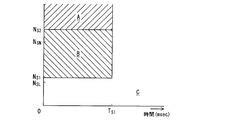
- FIG. 4 is an example of a processing division map that classifies signal processing divisions based on the determination results by the time determination unit 506a and the instantaneous rotation speed determination unit 507.
- the processing segment, the instantaneous rotational speed Nm and before the elapsed time reaches the first reference time T S1 is the second reference speed N S2 or more zones A
- the elapsed time is the first reference time T
- the instantaneous rotational speed Nm is classified into a zone B between the first reference speed NS1 and the second reference speed NS2, and another zone C.
- Zone C is the elapsed time and the instantaneous rotational speed Nm is equal to or less than the first reference speed N S1 zone even before reaching the first reference time T S1, after the elapsed time reaches the first reference time T S1 It consists of zones.
- the calculation operation unit 508 performs processing A for causing the rotation speed calculation unit 504 to hold the value of the rotation speed Nf calculated in the immediately preceding cycle. Further, when the elapsed time and the instantaneous rotation speed Nm are in the zone B, if no pulse signal is input, the value 0 is input to the rotation speed calculation unit 504 as the instantaneous rotation speed Nm without waiting for the determination of the non-input state. Processing B is performed. When the elapsed time and the instantaneous rotation speed Nm are in the zone C, the rotation speed calculation unit 504 performs normal processing.
- the normal process is to perform a wheel lock response process.
- the non-input duration time T WL is longer than the slip determination time T SL. until it exceeds the is held the rotation speed Nm of the immediately preceding rotational speed calculating section 504, the duration of the no-input enters a value 0 as an instantaneous rotational speed Nf Once beyond the wheel lock corresponding time T WL of the rotational speed calculating section 504 It is processing.
- the reason why the calculation operation unit 508 operates the calculation by the rotation speed calculation unit 504 according to the elapsed time and the instantaneous rotation speed Nm will be described below. This is due to slip determination and disconnection determination. First, the determination by the slip determination unit 501 and the disconnection determination unit 502 will be described.
- the slip determination unit 501 uses general failure determination logic, and the CVT 7 input shaft (primary shaft) detected by the rotation sensor 52 when the vehicle 100 is stopped (can be determined from the output 0 of the rotation sensor 55). rotational speed Nf of determining the belt slip CVT7 the slip determination speed N SL more condition continues slip determination time T SL or has occurred.
- any disconnection determination unit 502 uses a general failure determination logic, the rotational speed Nf detected by the rotation sensor 52 is no input of the pulse signal from the rotation sensor 52 from exceeding the breakage threshold engine speed N SN When it is determined, it is determined that the rotation sensor 52 is disconnected.
- the determination of the determination of the no-input state is the same logic as the above-described determination of the no-input state, and it is in the no-input state when the non-input state of the pulse signal continues for the no-input determination determination time T NIJ Confirm.
- the no-input determination determination time T NIJ may be set to a value equal to the above-described no-input determination time T NI. In order to make the disconnection determination more careful, the non-input determination determination time T NIJ is set longer than the no-input determination time T NI. May be set.
- This situation occurs when the second clutch 6 connecting the MG 3 and the CVT 7 is released and a sudden torque fluctuation occurs in the engine 1 or MG 3 (power plant) as schematically shown in FIG. To do.
- the cause of sudden fluctuations in the torque of the power plant is, for example, when the input torque of the engine 1 is suddenly applied to the input side of the second clutch 6 by engaging the first clutch 2 from the released state, or when the MG3 is operated as a starter motor.
- drag torque generated at the time of complete explosion of the engine when the stopped engine 1 is started can be mentioned.
- the sensing rotor 52b mounted on the input shaft (primary shaft) of the CVT 7 that is the output side of the second clutch 6 performs a slight swing back operation such as rotation or reverse rotation. Since the swinging operation of the sensing rotor 52b is very small but high speed, a pulse signal for one cycle is input from the rotation sensor 52 in a very short time (short cycle).
- the number of pulses of the pulse signal from the rotation sensor 52 due to the swinging back operation of the sensing rotor 52b is very small, and thereafter, a state where no pulse signal is input (no input state) continues.
- the rotational speed Nf after processing becomes smaller than the instantaneous rotational speed Nm by the filter processing by the rotational speed calculation unit 504.
- the instantaneous rotational speed Nm is The speed becomes extremely high, and the rotational speed Nf after processing also becomes high.
- the state of the rotational speed Nf slip determination speed N SL is sometimes held by wheel lock corresponding time T WL.
- the wheel lock response time T WL is set longer than the slip determination time T SL , so that when the vehicle 100 is stopped, the rotational speed Nf of the input shaft (primary shaft) of the CVT 7 is equal to or higher than the slip determination speed N SL. This means that the slip determination time TSL has been continued. Since the belt slip determination condition by the slip determination unit 501 is satisfied, it is erroneously determined that a belt slip has occurred even though no belt slip has occurred in the CVT 7.
- the input of the pulse signal is divided into those due to these special factors and others.
- the calculation by the rotation speed calculation unit 504 is operated by the calculation operation unit 508 only when necessary by dividing into a situation where it is erroneously determined and a case where it is not.
- the first reference speed NS1 and the second reference speed NS2 defined for the instantaneous rotation speed Nm for the zones A and B are set in correspondence with the above-described fail determination. That is, the first reference speed NS1 is set to be a minute amount faster than the slip determination speed NSL .
- the slip determination speed N SL for example, if the 450rpm is set, it sets a first reference speed N S1 slightly higher, for example, about 500rpm than this.
- the processed rotation speed Nf is smaller than the instantaneous rotation speed Nm by the filtering process by the rotation speed calculation unit 504, and therefore the first reference speed N S1 that is predetermined for the instantaneous rotation speed Nm is set accordingly. It is set slightly higher speed than the predetermined slip threshold velocity N SL for rotational speed Nf after the treatment.
- the rotational speed region of the first reference speed N S1 or more zones B is a rotational speed that can be generated when the input shaft of CVT7 under torque of the power plant 1 and 3 begins to rotate in the normal, the wheel In the lock handling process, even if there is no signal input, if the value before no input for a predetermined time is retained, the belt slip determination will be met, so the wheel lock handling process will be stopped to avoid this. is there.
- the first reference speed NS1 is set to be a minute amount higher than the slip determination speed NSL .
- the minute amount is It is preferable to set by paying attention to the fact that the rotational speed Nf after processing becomes smaller than the instantaneous rotational speed Nm.
- the first reference speed NS1 is simply set to a speed close to the slip determination speed NSL , there is a certain effect in avoiding conformity to the belt slip determination.
- the second reference speed N S2 is set based on the maximum value of the instantaneous rotational speed Nm that is assumed to be generated when the input shaft of CVT7 under torque of the power plant starts rotating normally.
- the second reference speed NS2 is set to a rotational speed higher than the disconnection determination rotational speed NSN .
- the disconnection threshold engine speed N SN is set to about 1000 rpm
- the second reference speed N S2 is set to about 1300 rpm.
- each process is performed as shown in the flowcharts of FIGS. 7 to 11 are repeatedly performed until the end of control in the same control cycle (for example, 10 msec) set when the control start condition is satisfied. It is assumed that the process of FIG. 6 is performed at a cycle that is much shorter than the control cycle of the processes of FIGS.
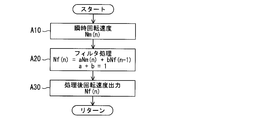
- the calculation of the rotation speed (post-processing rotation speed) Nf by the rotation speed calculation unit 504 takes in the instantaneous rotation speed Nm (n) at that time (step A10) as shown in FIG.
- the rotation speed Nf (n) is calculated by smoothing (n), for example, by filtering the expression (1) (step A20). Then, the post-processing rotation speed Nf (n) is output (step A30).
- the signal no input determination unit 505 determines whether or not there is no input of a pulse signal from the rotation sensor 52 (no pulse signal) (step B10).
- the non-input timer (count value is TC1) is counted (step B20), and it is determined whether the non-input timer count value TC1 is equal to or greater than the non-input determination count value TC N1 corresponding to the non-input determination time T NI. (Step B30).
- step B40 When the count value TC1 is no input determination count value TC N1 or more since the first flag F1 is set to 1 (step B40), and resets the count value TC1 to 0 (step B50).
- the first flag F1 indicates that the no-input state is determined with “1”, and indicates that the no-input state is not determined with “0”.
- Count value TC1 unless become non-input determination count value TC N1 or more, the process returns from step B30. On the other hand, if there is a pulse signal, the first flag F1 is set to 0 (step B60), and the count value TC1 is reset to 0 (step B50). As described above, it is determined whether or not the no-input state is determined in each control cycle.
- the time determination unit 506a determines whether or not the first flag F1 is 0 (step C10). If the first flag F1 is 0, a pulse signal is input (pulse signal). It is determined whether or not there is a signal (step C20). Here, if there is a pulse signal, it means that the pulse signal is switched from the non-input state to the input state, the post-input timer (count value is TC2) is counted (step C30), and the post-input timer count value TC2 is Then, it is determined whether or not the post-input reference count value TC S1 corresponding to the reference time T S1 is reached (step C40).
- the second flag F2 When the count value TC2 becomes less than the reference count value TC S1 after input, the second flag F2 is set to 1 (step C50), and the count value TC2 is reset to 0 (step C60).
- the second flag F2 indicates that the elapsed time is within the reference time T S1 with “1”, and indicates that there is no pulse signal or the elapsed time is greater than or equal to the reference time T S1 with “0”.
- step C40 If the count value TC2 is input after the reference count value TC S1 above, the process returns from step C40.
- the second flag F2 is set to 0 (step C70), and the count value TC2 is reset to 0 (step C60).
- the processing by the arithmetic operation unit 508 first determines whether or not the second flag F2 is 1, that is, whether or not the elapsed time is within the reference time T S1 (step D10). ) If the second flag F2 is 1 (the elapsed time is within the reference time TS1 ), the instantaneous rotational speed Nm is calculated from the pulse period (step D20). Next, comparison determines the instantaneous rotational speed Nm and the first reference speed N S1 and the second reference speed N S2 (Step D30, D40).
- the process A (hold rotational speed Nf after previous process) performed (step D50)
- the instantaneous rotational speed Nm is the first reference speed N S2 If it is in the zone between the first reference speed NS2 and the second reference speed NS2 , the process B (after that, if there is no pulse input, the instantaneous rotational speed Nm is set to 0) (step D60), the instantaneous rotational speed Nm is the first reference speed. If it is in the zone of speed NS2 or less, processing C (normal control with wheel lock control) is performed (step D70). In addition, when the elapsed time is outside the reference time T S1 , the process C (normal control with wheel lock control) is performed (step D70).
- the processing by the slip determination unit 501 is performed when the rotation speed Nf (n) of the input shaft (primary axis) of the CVT 7 detected by the rotation sensor 52 when the vehicle 100 stops is the slip determination speed. determines whether or not n SL more (step E10), the rotation speed Nf (n) to implement the counting of the slip determination speed n SL above value, if the slip determination timer (count value TC3) (step E20).
- the count value TC3 of the slip determination timer is determined whether to continue the slip determination count value TC SL least corresponding to the slip determination time T SL (step E30), the count value TC3 slip determination count value of the slip determination timer the CVT7 continuing TC SL or determines that the belt slip has occurred (step E40).
- step F10 it is determined whether or not the third flag F3 is 1 (step F10).
- the third flag F3 is set to 1 when the post-processing rotation speed Nf (n) exceeds the disconnection determination rotation speed NSN , and is then set to 1 when determining the non-input state of the pulse signal from the rotation sensor 52. Is held, and is reset to 0 when the pulse signal is input after the disconnection determination or before the determination of the non-input state of the pulse signal and the post-processing rotational speed Nf (n) does not exceed the disconnection determination rotational speed NSN .
- the third flag F3 is 1, it is determined whether the processed rotational speed Nf (n) exceeds the disconnection threshold engine speed N SN (step F20).
- the third flag F3 is set to 1 (step F30), and the count of the disconnection determination timer (count value TC4) is started from 0 ( Step F40) and return.
- the process after the rotation speed Nf does not exceed the breakage threshold engine speed N SN resets the count value TC4 disconnection determination timer to 0 (step F110), and resets the third flag F3 to 0 (step F 120), Return.
- step F50 it is determined whether or not the instantaneous rotational speed Nm (n) is 0 and whether or not the pulse signal from the rotation sensor 52 is not input (step F50). If the instantaneous rotational speed Nm (n) is not 0, the process proceeds to step F20 and the above processing is performed. If the instantaneous rotational speed Nm is 0, the disconnection determination timer is counted (step F60), and the count value TC4 of the disconnection determination timer becomes equal to or greater than the no-input determination determination value TC N1J corresponding to the no-input determination determination time T NIJ. (Step B70).
- Count TC4 disconnection determination timer is returned if not exceed the no-input confirmation determination count value TC N1J, When the count value TC4 disconnection determination timer is no input confirmation determination count value TC N1J above since, no input is determined As a result, it is determined that the rotation sensor 52 is disconnected (step F80). Thereafter, the count value TC4 of the disconnection determination timer is reset to 0 (step F90), the third flag F3 is reset to 0 (step F100), and the disconnection determination ends.
- the CVT 7 belt slip determination and the disconnection of the rotation sensor 52 are determined.
- the non-input of the pulse signal continues within the predetermined time (wheel lock corresponding time) TWL , the rotation speed immediately before the pulse signal non-input is maintained.
- the elapsed time after the pulse signal is changed from the non-input state to the input state is limited to the first reference time T1. . Therefore, the elapsed time is limited by the time it reaches the first reference time T1, the instantaneous rotational speed Nm is compared with a first reference speed N S1 and the second reference speed N S2, in accordance with the magnitude of the instantaneous rotational speed Nm Then, specific processing of processing A and processing B is performed.
- the instantaneous rotational speed Nm becomes the value of the normal second reference speed N S2 or more zones which can not be generated, it determines that the input of the pulse signal by the torque abrupt change, the instantaneous engine speed is not counted in the calculation of the rotational speed Then, the process A for holding the previous rotational speed value is performed. This prevents an excessively large post-processing rotational speed Nf from being erroneously calculated by an excessive instantaneous rotational speed Nm, thereby avoiding the influence on determination and control based on the post-processing rotational speed Nf. Particularly, excessive processing after the rotation speed Nf, because it may exceed the breakage threshold engine speed N SN, is avoided erroneously determined disconnection of the rotation sensor 52.
- processing B is performed in which 0 is immediately input to the rotational speed calculation means as the instantaneous rotational speed. Since the first reference speed NS1 is slightly higher than the slip determination speed NSL , when the wheel lock handling process is performed, the previous rotation speed is maintained only during the wheel lock handling time TWL. Although the slip determination speed or higher may continue for the slip determination time TSL or more and it may be erroneously determined that the belt is slipping, processing B is performed, so that erroneous determination of belt slip can be avoided.
- the power plant includes the engine 1 and the MG 3, but the power plant is not limited to this.
- the rotation speed of the input shaft is detected by a rotation sensor, and the rotation speed of the input shaft is judged to slip when the vehicle is stopped. It is widely applied when processing a pulse signal input from a rotation sensor in a vehicle that determines that a belt slip has occurred in the belt-type continuously variable transmission when the state of the speed N SL or higher continues for the slip determination time T SL or longer. be able to.
- the rotation sensor is not limited to an electromagnetic sensor as long as it can output a pulse signal, and can be widely applied to various systems such as an optical sensor.
- the processing C is performed assuming that the normal pulse determination has been made. It is preferable to implement.
Landscapes
- Engineering & Computer Science (AREA)
- General Engineering & Computer Science (AREA)
- Mechanical Engineering (AREA)
- Control Of Transmission Device (AREA)
- Electric Propulsion And Braking For Vehicles (AREA)
Abstract
Description
そこで、こうした誤判定を回避できるようにしたい。
車両のベルト式無段変速機の入力軸(プライマリ軸)の回転速度Nfを演算する場合、一般に、車輪ロックに対応する処理が実施される。つまり、車輪ロック時にはパルス信号は無入力となるが、このパルス信号の無入力がそのまま回転速度演算手段による回転速度Nfの演算に利用されてしまうと、回転速度Nfに基づく判定や制御に影響を及ぼすので、パルス信号の無入力の継続が所定時間(車輪ロック対応時間)TWL内であれば、パルス信号無入力の直前の回転速度Nfを保持する車輪ロック対応処理をすることで、回転速度Nfに基づく判定や制御への影響を回避している。
パワープラントのトルクを受けて入力軸が通常に回転し始める場合に、パルス信号が無入力状態から入力状態となるが、この場合、入力状態となった直後の瞬時回転速度は一定値(第2基準速度NS2)以内に収まるものと考えられる。そこで、瞬時回転速度が第2基準速度NS2以上になったら、トルク急変動によるパルス信号の入力と判断し、この瞬時回転速度Nmは回転速度Nfの演算にカウントしないで、直前の回転速度Nfの値を保持させることで、誤って過大な回転速度Nfを演算することが防止され、この回転速度Nfに基づく判定や制御への影響が回避される。
なお、以下に示す実施形態はあくまでも例示に過ぎず、以下の実施形態で明示しない種々の変形や技術の適用を排除する意図はない。
図1に示すように、本実施形態にかかる車両100は、内燃機関が用いられたエンジン1と、第1クラッチ2と、電動モータ(電動機)としても機能するモータジェネレータ(以下、MGともいう)3と、第1オイルポンプ4と、第2オイルポンプ5と、第2クラッチ6と、無段変速機(以下、CVTともいう)7と、駆動輪8と、統合コントローラ50とを備えている。なお、エンジン1及びMG3は、パワープラントとも総称する。
EVモードは、第1クラッチ2を解放し、MG3のみを駆動源として走行するモードである。このEVモードは、要求駆動力が低く、且つ、バッテリ10の充電量が十分ある時に選択される。
なお、これらHVモードとEHVモードとの切り替えがハンチングしないように、HVモードからEHVモードへの切り替え線は、EHVモードからHVモードへの切り替え線よりも高速且つアクセル開度大の側に設定されている。
ただし、a+b=1
時間判定部506aは、時間演算部506で演算された経過時間が基準時間TS1に達したか否かを判定する。
この状況は、断線判定部502による断線判定条件に適合してしまうため、回転センサ52の断線が生じていないにもかかわらず断線が発生したと誤判定することになる。
つまり、かかるパルス信号の入力は、瞬時であり、時間的には20msec程度の時間内に限られることが実機試験から判明している。そこで、このようなパルス信号の入力が発生すると想定される時間に基づいて、例えば想定時間に安全率fを乗算したりして余裕値αを加算したりして基準時間TS1を設定する。例えば、入力想定時間が20msecであり、安全率fを2、余裕値αを10msecとすれば、基準時間TS1は、50msec(=20msec×2+10msec)となる。
一方、パルス信号があれば、第1フラグF1を0とし(ステップB60)、カウント値TC1を0にリセットする(ステップB50)。
以上により、各制御周期で、無入力状態が確定したか否かが決まる。
一方、第1フラグF1が0でない場合やパルス信号の入力がない場合は、第2フラグF2を0とし(ステップC70)、カウント値TC2を0にリセットする(ステップC60)。
例えば、上記の実施形態では、パワープラントがエンジン1とMG3とから構成されるが、パワープラントはこれに限定されない。少なくともパワープラントにクラッチを介して断接可能に入力軸が接続されたベルト式無段変速機であって、入力軸の回転速度を回転センサで検出し、停車時に入力軸の回転速度がスリップ判定速度NSL以上の状態がスリップ判定時間TSL以上継続するとベルト式無段変速機にベルトスリップが生じていると判定する車両において、回転センサから入力されるパルス信号を処理する際に広く適用することができる。
なお、上記実施形態では言及していないが、本発明で着目するパルス入力時点が、回転センサの断線の判定中で断線確定前の場合には、正常なパルス判定があったものとして処理Cを実施することが好ましい。
Claims (4)
- パワープラントと、前記パワープラントにクラッチを介して断接可能に入力軸が接続されたベルト式無段変速機と、前記入力軸の回転を検出する回転センサと、停車時に前記入力軸の回転速度がスリップ判定速度NSL以上の状態がスリップ判定時間TSL以上継続すると前記ベルト式無段変速機にベルトスリップが生じていると判定するスリップ判定手段と、を有する車両に装備され、前記回転センサから入力されるパルス信号を処理する信号処理装置であって、
前記パルス信号の入力される周期から前記入力軸の瞬時回転速度Nmを演算する瞬時回転速度演算手段と、
前記瞬時回転速度Nmをフィルタ処理により平滑化して回転速度Nfを演算する回転速度演算手段と、
前記パルス信号が、無入力判定時間TNIだけ継続して無入力となった場合の無入力状態から入力状態となってからの経過時間を演算する時間演算手段と、
前記瞬時回転速度Nmを前記スリップ判定速度NSLの近傍速度である第1基準速度NS1及び前記第1基準速度NS1よりも高速の第2基準速度NS2と比較判定する瞬時回転速度判定手段と、
前記クラッチの解放時に、前記経過時間及び前記瞬時回転速度Nmに基づいて、前記回転速度演算手段による演算を操作する演算操作手段と、を備え、
前記演算操作手段は、
前記経過時間が基準時間TS1に達した以降は、
前記パルス信号の無入力が発生すると、該無入力の継続時間が車輪ロックに対応すべく設定され前記スリップ判定時間TSLよりも長い車輪ロック対応時間TWLを超えるまでは前記回転速度演算手段に直前の前記回転速度Nfを保持させ、前記無入力の継続時間が前記車輪ロック対応時間TWLを超えたら前記瞬時回転速度Nmとして0を前記回転速度演算手段に入力する車輪ロック対応処理を行ない、
前記経過時間が前記基準時間TS1に達するまでの間は、
前記判定手段により前記瞬時回転速度Nmが前記第1基準速度NS1以下のゾーンにあると判定された場合は、前記車輪ロック対応処理を行ない、
前記判定手段により前記瞬時回転速度が前記第1基準速度NS1と前記第2基準速度NS2との間のゾーンにあると判定された場合は、前記パルス信号の無入力が発生すると前記瞬時回転速度Nmとして0を前記回転速度演算手段に入力し、
前記判定手段により前記瞬時回転速度Nmが前記第2基準速度NS2以上のゾーンにあると判定された場合は、前記回転速度演算手段に直前に演算した前記回転速度Nfの値を保持させるようにした回転センサの信号処理装置。 - 前記基準時間T1は、前記クラッチの解放時に、前記パワープラントのトルクの急変動が前記入力軸に伝達されて微小量だけ瞬時回転したことで生じる短周期のパルス信号の発生しうる時間範囲を包含するように設定され、
前記第1基準速度NS1は、前記スリップ判定速度NSLよりも微小量だけ高速に設定され、前記第2基準速度NS2は、前記パワープラントのトルクを受けて前記入力軸が通常に回転し始める場合に発生可能な瞬時回転速度Nmの最大値に基づいて設定されている請求項1に記載の回転センサの信号処理装置。 - 前記回転速度が断線判定回転速度NSNを超えてからパルス信号の前記無入力状態が確定すると、前記回転センサが断線しているものと判定する断線判定手段を備え、
前記第2基準回転速度NS2は、前記断線判定回転速度NSNよりも大きく設定されると共に、前記クラッチの解放時に、前記パワープラントのトルクの急変動が前記入力軸に伝達されて微小量だけ瞬時回転したことで生じる短周期のパルス信号に基づく前記瞬時回転速度Nmを前記回転速度演算手段によりフィルタ処理することによって得られる前記回転速度Nfが、前記断線判定回転速度NSN以下になるように設定される請求項1または2に記載の回転センサの信号処理装置。 - 前記パワープラントは、内燃機関が用いられたエンジンと、前記エンジンと第1クラッチを介して接続された電気モータと、を備え、
前記電気モータの出力軸と、前記ベルト式無段変速機の前記入力軸との間には、前記クラッチとしての第2クラッチが介装され、
前記第1クラッチ及び前記第2クラッチは、締結モード及び開放モードの他に、滑り係合モードを有している請求項1~3のいずれか1項に記載の回転センサの信号処理装置。
Priority Applications (4)
| Application Number | Priority Date | Filing Date | Title |
|---|---|---|---|
| US14/914,328 US9920832B2 (en) | 2013-08-27 | 2014-06-27 | Signal processing device for rotation sensor |
| CN201480046664.XA CN105473905B (zh) | 2013-08-27 | 2014-06-27 | 旋转传感器的信号处理装置 |
| KR1020167001782A KR101780904B1 (ko) | 2013-08-27 | 2014-06-27 | 회전 센서의 신호 처리 장치 |
| EP14839501.5A EP3040585B1 (en) | 2013-08-27 | 2014-06-27 | Signal processing device for rotation sensor |
Applications Claiming Priority (2)
| Application Number | Priority Date | Filing Date | Title |
|---|---|---|---|
| JP2013175827A JP6027507B2 (ja) | 2013-08-27 | 2013-08-27 | 回転センサの信号処理装置 |
| JP2013-175827 | 2013-08-27 |
Publications (1)
| Publication Number | Publication Date |
|---|---|
| WO2015029572A1 true WO2015029572A1 (ja) | 2015-03-05 |
Family
ID=52586150
Family Applications (1)
| Application Number | Title | Priority Date | Filing Date |
|---|---|---|---|
| PCT/JP2014/067108 Ceased WO2015029572A1 (ja) | 2013-08-27 | 2014-06-27 | 回転センサの信号処理装置 |
Country Status (6)
| Country | Link |
|---|---|
| US (1) | US9920832B2 (ja) |
| EP (1) | EP3040585B1 (ja) |
| JP (1) | JP6027507B2 (ja) |
| KR (1) | KR101780904B1 (ja) |
| CN (1) | CN105473905B (ja) |
| WO (1) | WO2015029572A1 (ja) |
Families Citing this family (9)
| Publication number | Priority date | Publication date | Assignee | Title |
|---|---|---|---|---|
| US10648554B2 (en) | 2014-09-02 | 2020-05-12 | Polaris Industries Inc. | Continuously variable transmission |
| KR20170117544A (ko) * | 2015-03-26 | 2017-10-23 | 쟈트코 가부시키가이샤 | 차량용 자동 변속기의 제어 장치 |
| JP6770317B2 (ja) * | 2016-01-26 | 2020-10-14 | ジヤトコ株式会社 | パワートレインの制御装置及びパワートレインの制御方法 |
| CN107436362A (zh) * | 2017-08-25 | 2017-12-05 | 湖南三德科技股份有限公司 | 一种煤样检测线破碎机转速检测方法、装置及破碎机 |
| WO2019182951A1 (en) | 2018-03-19 | 2019-09-26 | Polaris Industries Inc. | Electronic cvt with friction clutch |
| MX2020009417A (es) | 2018-03-19 | 2020-10-05 | Polaris Inc | Transmision continuamente variable. |
| JP6754415B2 (ja) * | 2018-11-16 | 2020-09-09 | 本田技研工業株式会社 | 車両制御装置、車両及び車両制御方法 |
| US12504070B2 (en) | 2021-01-29 | 2025-12-23 | Polaris Industries Inc. | Electronically-controlled continuously variable transmission for a utility vehicle |
| CN119058563B (zh) * | 2024-08-28 | 2025-12-12 | 长城汽车股份有限公司 | 一种车辆皮带打滑诊断方法、存储介质和车辆 |
Citations (6)
| Publication number | Priority date | Publication date | Assignee | Title |
|---|---|---|---|---|
| JPS6362954A (ja) * | 1986-08-29 | 1988-03-19 | Fuji Heavy Ind Ltd | Vベルト式無段変速機のベルトスリツプ検出方法 |
| JP2003106442A (ja) * | 2001-09-28 | 2003-04-09 | Toyota Motor Corp | 無段変速機の滑り検出装置 |
| JP2003214905A (ja) | 2002-01-23 | 2003-07-30 | Denso Corp | 回転検出装置 |
| JP2005344860A (ja) * | 2004-06-03 | 2005-12-15 | Toyota Motor Corp | 無段変速機の滑り検出装置 |
| JP2013148110A (ja) * | 2012-01-17 | 2013-08-01 | Toyota Motor Corp | 変速機の異常判定装置 |
| JP2013151175A (ja) * | 2012-01-24 | 2013-08-08 | Jatco Ltd | ハイブリッド車のエンジン始動制御装置 |
Family Cites Families (7)
| Publication number | Priority date | Publication date | Assignee | Title |
|---|---|---|---|---|
| JP2722856B2 (ja) * | 1991-05-30 | 1998-03-09 | 日産自動車株式会社 | 内燃機関のアイドル回転制御装置 |
| US5627750A (en) * | 1993-12-29 | 1997-05-06 | Toyota Jidosha Kabushiki Kaisha | Clutch slip control device and method of manufacturing the same, clutch slip control method, and vehicle control device |
| US5848370A (en) * | 1995-04-03 | 1998-12-08 | Nippondenso Co., Ltd. | Hydraulic pressure control apparatus for automatic transmission |
| JP5247000B2 (ja) * | 2005-12-21 | 2013-07-24 | 日産自動車株式会社 | 車両のコースト減速制御装置 |
| JP5359036B2 (ja) * | 2008-06-03 | 2013-12-04 | 日産自動車株式会社 | エンジン自動停止制御装置付き車両の変速機に用いる電動オイルポンプの故障判定装置 |
| JP5080525B2 (ja) * | 2009-03-30 | 2012-11-21 | ジヤトコ株式会社 | ハイブリッド車両の制御装置 |
| WO2010125666A1 (ja) * | 2009-04-30 | 2010-11-04 | ジヤトコ株式会社 | ベルト式無段変速機の制御装置と制御方法 |
-
2013
- 2013-08-27 JP JP2013175827A patent/JP6027507B2/ja active Active
-
2014
- 2014-06-27 KR KR1020167001782A patent/KR101780904B1/ko not_active Expired - Fee Related
- 2014-06-27 WO PCT/JP2014/067108 patent/WO2015029572A1/ja not_active Ceased
- 2014-06-27 US US14/914,328 patent/US9920832B2/en active Active
- 2014-06-27 CN CN201480046664.XA patent/CN105473905B/zh active Active
- 2014-06-27 EP EP14839501.5A patent/EP3040585B1/en active Active
Patent Citations (6)
| Publication number | Priority date | Publication date | Assignee | Title |
|---|---|---|---|---|
| JPS6362954A (ja) * | 1986-08-29 | 1988-03-19 | Fuji Heavy Ind Ltd | Vベルト式無段変速機のベルトスリツプ検出方法 |
| JP2003106442A (ja) * | 2001-09-28 | 2003-04-09 | Toyota Motor Corp | 無段変速機の滑り検出装置 |
| JP2003214905A (ja) | 2002-01-23 | 2003-07-30 | Denso Corp | 回転検出装置 |
| JP2005344860A (ja) * | 2004-06-03 | 2005-12-15 | Toyota Motor Corp | 無段変速機の滑り検出装置 |
| JP2013148110A (ja) * | 2012-01-17 | 2013-08-01 | Toyota Motor Corp | 変速機の異常判定装置 |
| JP2013151175A (ja) * | 2012-01-24 | 2013-08-08 | Jatco Ltd | ハイブリッド車のエンジン始動制御装置 |
Non-Patent Citations (1)
| Title |
|---|
| See also references of EP3040585A4 |
Also Published As
| Publication number | Publication date |
|---|---|
| KR20160024944A (ko) | 2016-03-07 |
| US20160215878A1 (en) | 2016-07-28 |
| JP6027507B2 (ja) | 2016-11-16 |
| EP3040585A1 (en) | 2016-07-06 |
| KR101780904B1 (ko) | 2017-09-21 |
| US9920832B2 (en) | 2018-03-20 |
| EP3040585A4 (en) | 2016-11-30 |
| EP3040585B1 (en) | 2019-08-07 |
| CN105473905A (zh) | 2016-04-06 |
| CN105473905B (zh) | 2017-07-07 |
| JP2015045354A (ja) | 2015-03-12 |
Similar Documents
| Publication | Publication Date | Title |
|---|---|---|
| JP6027507B2 (ja) | 回転センサの信号処理装置 | |
| JP5981650B2 (ja) | ハイブリッド車両の故障判定装置及びその故障判定方法 | |
| US9545918B2 (en) | Control device of hybrid vehicle | |
| JP2011201370A (ja) | ハイブリッド車輌の制御装置 | |
| JP6158915B2 (ja) | ハイブリッド車両の異常検知装置及び異常検知方法 | |
| KR20160033175A (ko) | 하이브리드 차량의 제어 장치 | |
| US20160076644A1 (en) | Temperature warning device and temperature warning method of friction element | |
| JP6152422B2 (ja) | ハイブリッド車両の故障判定装置及びその故障判定方法 | |
| JPWO2015076041A1 (ja) | 無段変速機の制御装置 | |
| CN105073538B (zh) | 混合动力车辆的故障判定装置及其故障判定方法 | |
| JP2021075100A (ja) | 車両用制御装置 | |
| JP6207269B2 (ja) | ベルト式無段変速機の制御装置 | |
| JP6355308B2 (ja) | ベルト式無段変速機の制御装置 | |
| JP6588199B2 (ja) | 車両の制御装置 | |
| JP6291171B2 (ja) | 車両用制御装置 | |
| JP6400148B2 (ja) | ベルト式無段変速機の制御装置 | |
| JP5935549B2 (ja) | 車両のエンジン自動停止制御装置 | |
| JP6560543B2 (ja) | 車両用制御装置 |
Legal Events
| Date | Code | Title | Description |
|---|---|---|---|
| WWE | Wipo information: entry into national phase |
Ref document number: 201480046664.X Country of ref document: CN |
|
| 121 | Ep: the epo has been informed by wipo that ep was designated in this application |
Ref document number: 14839501 Country of ref document: EP Kind code of ref document: A1 |
|
| ENP | Entry into the national phase |
Ref document number: 20167001782 Country of ref document: KR Kind code of ref document: A |
|
| REEP | Request for entry into the european phase |
Ref document number: 2014839501 Country of ref document: EP |
|
| WWE | Wipo information: entry into national phase |
Ref document number: 14914328 Country of ref document: US Ref document number: 2014839501 Country of ref document: EP |
|
| NENP | Non-entry into the national phase |
Ref country code: DE |