WO2015029772A1 - 遠隔サーバ - Google Patents
遠隔サーバ Download PDFInfo
- Publication number
- WO2015029772A1 WO2015029772A1 PCT/JP2014/071313 JP2014071313W WO2015029772A1 WO 2015029772 A1 WO2015029772 A1 WO 2015029772A1 JP 2014071313 W JP2014071313 W JP 2014071313W WO 2015029772 A1 WO2015029772 A1 WO 2015029772A1
- Authority
- WO
- WIPO (PCT)
- Prior art keywords
- remote server
- engine
- correlation
- information
- load factor
- Prior art date
- Legal status (The legal status is an assumption and is not a legal conclusion. Google has not performed a legal analysis and makes no representation as to the accuracy of the status listed.)
- Ceased
Links
Images


Classifications
-
- F—MECHANICAL ENGINEERING; LIGHTING; HEATING; WEAPONS; BLASTING
- F02—COMBUSTION ENGINES; HOT-GAS OR COMBUSTION-PRODUCT ENGINE PLANTS
- F02D—CONTROLLING COMBUSTION ENGINES
- F02D41/00—Electrical control of supply of combustible mixture or its constituents
- F02D41/22—Safety or indicating devices for abnormal conditions
-
- F—MECHANICAL ENGINEERING; LIGHTING; HEATING; WEAPONS; BLASTING
- F02—COMBUSTION ENGINES; HOT-GAS OR COMBUSTION-PRODUCT ENGINE PLANTS
- F02D—CONTROLLING COMBUSTION ENGINES
- F02D41/00—Electrical control of supply of combustible mixture or its constituents
- F02D41/24—Electrical control of supply of combustible mixture or its constituents characterised by the use of digital means
- F02D41/26—Electrical control of supply of combustible mixture or its constituents characterised by the use of digital means using computer, e.g. microprocessor
- F02D41/266—Electrical control of supply of combustible mixture or its constituents characterised by the use of digital means using computer, e.g. microprocessor the computer being backed-up or assisted by another circuit, e.g. analogue
-
- G—PHYSICS
- G05—CONTROLLING; REGULATING
- G05B—CONTROL OR REGULATING SYSTEMS IN GENERAL; FUNCTIONAL ELEMENTS OF SUCH SYSTEMS; MONITORING OR TESTING ARRANGEMENTS FOR SUCH SYSTEMS OR ELEMENTS
- G05B13/00—Adaptive control systems, i.e. systems automatically adjusting themselves to have a performance which is optimum according to some preassigned criterion
- G05B13/02—Adaptive control systems, i.e. systems automatically adjusting themselves to have a performance which is optimum according to some preassigned criterion electric
- G05B13/0205—Adaptive control systems, i.e. systems automatically adjusting themselves to have a performance which is optimum according to some preassigned criterion electric not using a model or a simulator of the controlled system
- G05B13/026—Adaptive control systems, i.e. systems automatically adjusting themselves to have a performance which is optimum according to some preassigned criterion electric not using a model or a simulator of the controlled system using a predictor
-
- G—PHYSICS
- G07—CHECKING-DEVICES
- G07C—TIME OR ATTENDANCE REGISTERS; REGISTERING OR INDICATING THE WORKING OF MACHINES; GENERATING RANDOM NUMBERS; VOTING OR LOTTERY APPARATUS; ARRANGEMENTS, SYSTEMS OR APPARATUS FOR CHECKING NOT PROVIDED FOR ELSEWHERE
- G07C5/00—Registering or indicating the working of vehicles
- G07C5/008—Registering or indicating the working of vehicles communicating information to a remotely located station
-
- E—FIXED CONSTRUCTIONS
- E02—HYDRAULIC ENGINEERING; FOUNDATIONS; SOIL SHIFTING
- E02F—DREDGING; SOIL-SHIFTING
- E02F9/00—Component parts of dredgers or soil-shifting machines, not restricted to one of the kinds covered by groups E02F3/00 - E02F7/00
- E02F9/20—Drives; Control devices
- E02F9/2025—Particular purposes of control systems not otherwise provided for
- E02F9/2054—Fleet management
-
- F—MECHANICAL ENGINEERING; LIGHTING; HEATING; WEAPONS; BLASTING
- F02—COMBUSTION ENGINES; HOT-GAS OR COMBUSTION-PRODUCT ENGINE PLANTS
- F02D—CONTROLLING COMBUSTION ENGINES
- F02D9/00—Controlling engines by throttling air or fuel-and-air induction conduits or exhaust conduits
- F02D9/02—Controlling engines by throttling air or fuel-and-air induction conduits or exhaust conduits concerning induction conduits
- F02D2009/0201—Arrangements; Control features; Details thereof
- F02D2009/0223—Cooling water temperature
-
- F—MECHANICAL ENGINEERING; LIGHTING; HEATING; WEAPONS; BLASTING
- F02—COMBUSTION ENGINES; HOT-GAS OR COMBUSTION-PRODUCT ENGINE PLANTS
- F02D—CONTROLLING COMBUSTION ENGINES
- F02D2200/00—Input parameters for engine control
- F02D2200/02—Input parameters for engine control the parameters being related to the engine
- F02D2200/021—Engine temperature
- F02D2200/022—Estimation of engine temperature
-
- G—PHYSICS
- G07—CHECKING-DEVICES
- G07C—TIME OR ATTENDANCE REGISTERS; REGISTERING OR INDICATING THE WORKING OF MACHINES; GENERATING RANDOM NUMBERS; VOTING OR LOTTERY APPARATUS; ARRANGEMENTS, SYSTEMS OR APPARATUS FOR CHECKING NOT PROVIDED FOR ELSEWHERE
- G07C5/00—Registering or indicating the working of vehicles
- G07C5/08—Registering or indicating performance data other than driving, working, idle, or waiting time, with or without registering driving, working, idle or waiting time
- G07C5/0816—Indicating performance data, e.g. occurrence of a malfunction
-
- Y—GENERAL TAGGING OF NEW TECHNOLOGICAL DEVELOPMENTS; GENERAL TAGGING OF CROSS-SECTIONAL TECHNOLOGIES SPANNING OVER SEVERAL SECTIONS OF THE IPC; TECHNICAL SUBJECTS COVERED BY FORMER USPC CROSS-REFERENCE ART COLLECTIONS [XRACs] AND DIGESTS
- Y02—TECHNOLOGIES OR APPLICATIONS FOR MITIGATION OR ADAPTATION AGAINST CLIMATE CHANGE
- Y02T—CLIMATE CHANGE MITIGATION TECHNOLOGIES RELATED TO TRANSPORTATION
- Y02T10/00—Road transport of goods or passengers
- Y02T10/10—Internal combustion engine [ICE] based vehicles
- Y02T10/40—Engine management systems
Definitions
- the present invention relates to a remote server technique for predicting the occurrence of engine overheating.
- a remote server is a service that provides some service to a distant user.
- the operating status of work machines is remotely monitored by a remote server, and maintenance information and the like are provided to users.
- Patent Document 1 discloses a configuration in which a component life of a work machine is managed by a remote server.
- Patent Document 2 discloses a configuration for determining occurrence of overheating of an engine of a construction machine.
- the engine disclosed in Patent Document 2 it is necessary to detect the temperature of each cylinder of the engine. Therefore, for example, it cannot be applied to an engine in which a temperature sensor is not provided for each cylinder.
- the remote server disclosed in Patent Document 1 does not disclose a configuration for predicting engine overheating.
- the problem to be solved by the present invention is to provide a remote server that can predict engine overheating.
- the engine load factor movement is calculated by calculating a moving average value of the engine load factor at a predetermined interval in the remote server that receives the engine speed information, the engine load factor information, and the cooling water temperature information. It is preferable to calculate the correlation between the average value and the cooling water temperature, and to predict the occurrence of overheating when the correlation in a certain predetermined period is a predetermined difference from the correlation up to the predetermined period.
- the engine output is calculated from the engine speed information and the engine load factor information in the remote server that receives the engine speed information, the engine load factor information, and the cooling water temperature information.
- the engine output moving average value is calculated, the correlation between the engine output moving average value and the coolant temperature is calculated, and the correlation during a predetermined period is a predetermined difference from the correlation up to the predetermined period. In this state, the occurrence of overheating is predicted.
- the outside air temperature information or the atmospheric pressure information is received, and the cooling water temperature information is corrected based on the altitude calculated from the outside air temperature information or the atmospheric pressure information.
- the remote server of the present invention it is possible to predict the occurrence of engine overheating without depending on the temperature detection of each cylinder.
- the calculation load for predicting the occurrence of overheating is not applied to the individual engine controller, and the prediction logic can be easily updated.
- the schematic diagram which shows the structure of a remote server system. Another schematic diagram showing a configuration of a remote server system.
- the graph which shows the correlation with an engine load factor and cooling water temperature.
- the flowchart which shows the flow of overheat prediction control.
- the graph which shows the correlation with an engine output and cooling water temperature.
- the flowchart which shows the flow of overheat prediction control.
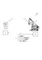
- the remote server system 100 will be described with reference to FIG. In FIG. 1, the remote server system 100 is schematically shown.
- the remote server system 100 is a system according to an embodiment of the remote server of the present invention.
- the remote server system 100 is a system that provides some service to a distant user.
- the remote server system 100 according to the present embodiment provides a service from a remote information center 110 to a user who uses a turning work vehicle 3 as a construction machine via an overseas communication company 130 and a domestic communication company 120 in the world. It is a system that provides
- the remote server system 100 will be further described with reference to FIG. In FIG. 2, the remote server system 100 is schematically shown.
- the remote server system 100 is a system that predicts overheating of an engine (not shown) that drives the turning work vehicle 3 and warns the user who uses the turning work vehicle 3 that overheating has occurred.
- the remote server system 100 is constructed so that, for example, the remote server 5 provided in the remote information center 110 (see FIG. 1) and the terminal server 6 provided in the turning work vehicle 3 can communicate with each other.
- the remote server 5 is constructed so as to be communicable with terminal servers 6... 6 provided in a large number of turning work vehicles 3.
- the terminal server 6 includes at least the date and time of operation as the operation date information of the turning work vehicle 3, the engine speed Ne as the engine speed information, and the engine load factor as the engine load factor information. It is assumed that the coolant temperature Tw is transmitted to the remote server 5 as L and engine coolant temperature information.
- the turning work vehicle 3 of this embodiment is equipped with a common rail engine as an engine.
- the engine speed Ne the engine speed Ne detected by the engine speed sensor is transmitted to the remote server 5.
- the coolant temperature Tw detected by the engine coolant temperature sensor is transmitted to the remote server 5 as the coolant temperature Tw.
- the engine load factor L is transmitted to the remote server 5 as a ratio of the injection amount commanded by the ECU (Engine Control Unit) to the maximum injection amount at the engine speed Ne.
- the rack position detected by the rack position sensor is the engine load factor L.
- the accelerator rotation amount detected by the accelerator opening sensor becomes the engine load factor L.
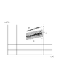
- the horizontal axis represents the engine load factor L
- the vertical axis represents the coolant temperature Tw
- the correlation between the engine load factor L and the coolant temperature Tw is represented by a graph.
- the engine load factor L represents a moving average value every 10 minutes.
- plot group A in the graph plots the correlation between the engine load factor L and the coolant temperature Tw until the previous operation of the turning work vehicle 3.
- plot group B in the graph plots the correlation between the engine load factor L and the coolant temperature Tw in the current operation of the same turning work vehicle 3.
- the correlation between the engine load factor L and the coolant temperature Tw shows the same tendency.
- the approximate curve A1 is calculated from a plot of the correlation between the engine load factor L and the coolant temperature Tw until the previous operation.
- the correlation between the engine load factor L and the coolant temperature Tw shows a tendency that the coolant temperature Tw is higher than that in the region A.
- the approximate curve B1 is calculated from a plot of the correlation between the engine load factor L and the coolant temperature Tw in the current operation.
- the engine coolant temperature Tw is substantially proportional to the engine load factor L.
- the engine overheating is a state where the engine is overheated and malfunctions.
- the engine is often overheated due to insufficient cooling capacity. Insufficient cooling capacity can often be detected by an increase in the coolant temperature Tw.
- the engine overheating can be prevented from occurring if it is detected that the cooling water temperature Tw is different from the engine load factor L.
- the plot group B in the graph shows a sign of engine overheating.
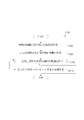
- the overheat prediction control S100 will be described with reference to FIG. In addition, in FIG. 4, the flow of overheat prediction control S100 is represented with the flowchart.
- the overheat prediction control S100 is control in which the remote server 5 predicts engine overheating.
- step S110 the remote server 5 acquires the engine load factor L and the coolant temperature Tw as information in the current operation of the turning work vehicle 3.
- the engine load factor L acquires the moving average value for every 10 minutes as information.
- step S120 the remote server 5 calculates an approximate curve B1 indicating a correlation between the engine load factor L and the coolant temperature Tw from the acquired engine load factor L (moving average value) and the coolant temperature Tw.
- step S130 the remote server 5 calculates the approximate curve B1 calculated in the current operation and the approximate curve A1 calculated in the previous operation, and determines whether the approximate curve B1 is within the predetermined region R1. .
- the approximate curve A1 calculated in the previous operation is limited to the one in which the engine is operating normally.
- the range of the predetermined region R1 is a range in the vicinity of the calculated approximate curve A1, and is calculated as a region including an error.
- the remote server 5 proceeds to step S140 if the approximate curve B1 is within the predetermined region R1. On the other hand, if the approximate curve B1 is not within the range of the predetermined region R1, the overheat prediction control S100 is terminated.
- step S140 the remote server 5 warns the user that the engine of the turning work vehicle 3 may be overheated, and ends the overheat prediction control S100.
- the remote server 5 warns the user that the engine of the turning work vehicle 3 may be overheated, and ends the overheat prediction control S100.
- the effects of the remote server 5 and the overheat prediction control S100 will be described. According to the remote server 5 and the overheat prediction control S100, occurrence of engine overheating can be predicted. In addition, the calculation load for predicting the occurrence of overheating is not applied to the ECU of the turning work vehicle 3, and the prediction logic can be easily updated.
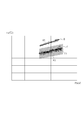
- the horizontal axis represents the engine output P
- the vertical axis represents the cooling water temperature Tw
- the correlation between the engine output P and the cooling water temperature Tw is represented by a graph.
- the engine output P represents a moving average value every 10 minutes.
- the C plot group in the graph plots the correlation between the engine output P and the coolant temperature Tw until the previous operation of the turning work vehicle 3. Further, it is assumed that a region D in the graph plots a correlation between the engine output P and the coolant temperature Tw in the current operation of the same turning work vehicle 3.
- the correlation between the engine output P and the coolant temperature Tw shows the same tendency.
- the approximate curve C1 is calculated from a plot of the correlation between the engine output P and the coolant temperature Tw until the previous operation.
- the correlation between the engine output P and the coolant temperature Tw tends to be higher than that in the region C.
- the approximate curve D1 is calculated from a plot of the correlation between the engine output P and the coolant temperature Tw in the current operation.
- the engine coolant temperature Tw is proportional to the engine output P with high accuracy compared to the engine load factor L described above.
- a group of plots D indicates a sign of engine overheating.
- Another overheat prediction control S200 will be described with reference to FIG. In addition, in FIG. 6, the flow of another overheat prediction control S200 is represented by the flowchart.
- step S210 the remote server 5 acquires the engine output P and the coolant temperature Tw as information in the operation of the turning work vehicle 3 up to the previous time.
- the engine output P acquires the moving average value for every 10 minutes as information.
- step S220 the remote server 5 calculates an approximate curve D1 indicating a correlation between the engine output P and the coolant temperature Tw from the acquired engine output P (moving average value) and the coolant temperature Tw.
- step S230 the remote server 5 calculates a difference between the approximate curve D1 calculated in the current operation and the approximate curve C1 calculated in the previous operation, and determines whether the approximate curve D1 is within the predetermined region R2. judge. Note that the approximate curve C1 calculated in the previous operation is limited to the one in which the engine is operating normally.
- the range of the predetermined region R2 is a range in the vicinity of the calculated approximate curve C1, and is calculated as a region including an error.
- the remote server 5 proceeds to step S240. On the other hand, if the approximate curve D1 is not within the range of the predetermined region R2, the overheat prediction control S200 is terminated.
- step S240 the remote server 5 warns the user that the engine of the turning work vehicle 3 may be overheated, and ends the overheat prediction control S100.
- the remote server 5 and another overheat prediction control S200 will be described. According to the remote server 5 and another overheat prediction control S200, it is possible to accurately predict the occurrence of engine overheating. In addition, the calculation load for predicting the occurrence of overheating is not applied to the ECU of the turning work vehicle 3, and the prediction logic can be easily updated.
- the cooling water temperature Tw detected by the cooling water temperature sensor is directly used.
- the present invention is not limited to this.
- the cooling water temperature Tw may be corrected using the outside air temperature detected by the outside air temperature sensor or the altitude calculated from the atmospheric pressure detected by the atmospheric pressure sensor.
- the present invention can be used for a remote server.
Landscapes
- Engineering & Computer Science (AREA)
- General Engineering & Computer Science (AREA)
- Chemical & Material Sciences (AREA)
- Combustion & Propulsion (AREA)
- Mechanical Engineering (AREA)
- Computer Hardware Design (AREA)
- Physics & Mathematics (AREA)
- General Physics & Mathematics (AREA)
- Microelectronics & Electronic Packaging (AREA)
- Artificial Intelligence (AREA)
- Health & Medical Sciences (AREA)
- Computer Vision & Pattern Recognition (AREA)
- Evolutionary Computation (AREA)
- Medical Informatics (AREA)
- Software Systems (AREA)
- Automation & Control Theory (AREA)
- Combined Controls Of Internal Combustion Engines (AREA)
- Operation Control Of Excavators (AREA)
- Mining & Mineral Resources (AREA)
- Civil Engineering (AREA)
- Structural Engineering (AREA)
- Management, Administration, Business Operations System, And Electronic Commerce (AREA)
Abstract
Description
なお、図1では、遠隔サーバシステム100を模式的に表している。
なお、図2では、遠隔サーバシステム100を模式的に表している。
なお、図3では、横軸にエンジン負荷率Lを表し、縦軸に冷却水温度Twを表し、エンジン負荷率Lと冷却水温度Twとの相関をグラフによって表している。なお、エンジン負荷率Lは、10分毎の移動平均値を表している。
なお、図4では、オーバーヒート予測制御S100の流れをフローチャートにて表している。
遠隔サーバ5及びオーバーヒート予測制御S100によれば、エンジンのオーバーヒートの発生を予測できる。また、旋回作業車3のECUにオーバーヒートの発生を予測する演算負荷が掛からず、予測ロジックの更新も容易である。
なお、図5では、横軸にエンジン出力Pを表し、縦軸に冷却水温度Twを表し、エンジン出力Pと冷却水温度Twとの相関をグラフによって表している。なお、エンジン出力Pは、10分毎の移動平均値を表している。
なお、図6では、別のオーバーヒート予測制御S200の流れをフローチャートにて表している。
遠隔サーバ5及び別のオーバーヒート予測制御S200によれば、エンジンのオーバーヒートの発生を精度良く予測できる。また、旋回作業車3のECUにオーバーヒートの発生を予測する演算負荷が掛からず、予測ロジックの更新も容易である。
5 遠隔サーバ
6 端末サーバ
100 遠隔サーバシステム
Claims (3)
- エンジン回転数情報、エンジンの負荷率情報及び冷却水温度情報を受信する遠隔サーバにおいて、所定間隔のエンジン負荷率の移動平均値を演算して、エンジン負荷率の移動平均値と冷却水温度との相関関係を演算し、ある所定期間での相関関係が当該所定期間までの相関関係に対して所定の相違状態である場合にオーバーヒートの発生を予測する、
遠隔サーバ。 - エンジン回転数情報、エンジンの負荷率情報及び冷却水温度情報を受信する遠隔サーバにおいて、エンジン回転数情報及びエンジンの負荷率情報からエンジン出力を算出し、所定間隔のエンジン出力の移動平均値を演算して、エンジン出力の移動平均値と冷却水温度との相関関係を演算し、ある所定期間での相関関係が当該所定期間までの相関関係に対して所定の相違状態である場合にオーバーヒートの発生を予測する、
遠隔サーバ。 - 請求項1又は2に記載の遠隔サーバであって、
外気温度情報又は大気圧情報を受信し、
冷却水温度情報を外気温度情報或いは大気圧情報から演算される標高に基づいて補正する、
遠隔サーバ。
Priority Applications (4)
| Application Number | Priority Date | Filing Date | Title |
|---|---|---|---|
| US14/914,398 US9777661B2 (en) | 2013-08-28 | 2014-08-12 | Remote server |
| KR1020167007202A KR101747835B1 (ko) | 2013-08-28 | 2014-08-12 | 원격 서버 |
| EP14841284.4A EP3040545B1 (en) | 2013-08-28 | 2014-08-12 | Remote server |
| CN201480048062.8A CN105492747B (zh) | 2013-08-28 | 2014-08-12 | 远程服务器 |
Applications Claiming Priority (2)
| Application Number | Priority Date | Filing Date | Title |
|---|---|---|---|
| JP2013176840A JP6209024B2 (ja) | 2013-08-28 | 2013-08-28 | 遠隔サーバ |
| JP2013-176840 | 2013-08-28 |
Publications (1)
| Publication Number | Publication Date |
|---|---|
| WO2015029772A1 true WO2015029772A1 (ja) | 2015-03-05 |
Family
ID=52586341
Family Applications (1)
| Application Number | Title | Priority Date | Filing Date |
|---|---|---|---|
| PCT/JP2014/071313 Ceased WO2015029772A1 (ja) | 2013-08-28 | 2014-08-12 | 遠隔サーバ |
Country Status (6)
| Country | Link |
|---|---|
| US (1) | US9777661B2 (ja) |
| EP (1) | EP3040545B1 (ja) |
| JP (1) | JP6209024B2 (ja) |
| KR (1) | KR101747835B1 (ja) |
| CN (1) | CN105492747B (ja) |
| WO (1) | WO2015029772A1 (ja) |
Families Citing this family (4)
| Publication number | Priority date | Publication date | Assignee | Title |
|---|---|---|---|---|
| KR101856372B1 (ko) | 2016-10-20 | 2018-05-10 | 현대자동차주식회사 | 전기자동차용 구동모터 냉각 제어방법 |
| JP2022074325A (ja) * | 2020-11-04 | 2022-05-18 | 日野自動車株式会社 | クローズドベンチレータ診断装置及びクローズドベンチレータ診断システム |
| DE102022115392A1 (de) | 2022-06-21 | 2023-12-21 | Deere & Company | Kontrollanordnung zur selbsttätigen Steuerung einer landwirtschaftlichen Arbeitsmaschine, Arbeitsmaschine und Verfahren |
| US12196147B2 (en) * | 2022-09-30 | 2025-01-14 | Nissan North America, Inc. | Engine malfunction determination system |
Citations (6)
| Publication number | Priority date | Publication date | Assignee | Title |
|---|---|---|---|---|
| JPH10205421A (ja) * | 1997-01-23 | 1998-08-04 | Fujitsu Ten Ltd | 車両用内燃機関の遠隔始動装置および回転数検出装置 |
| JP2004185190A (ja) * | 2002-12-02 | 2004-07-02 | Hitachi Constr Mach Co Ltd | 建設機械の情報処理システム及び建設機械の情報処理方法 |
| WO2005043481A1 (ja) * | 2003-10-31 | 2005-05-12 | Komatsu Ltd. | 作業機械の管理システム |
| JP2005207413A (ja) | 2003-12-26 | 2005-08-04 | Hitachi Constr Mach Co Ltd | 建設機械のエンジン保護装置及び保護方法 |
| JP2007100305A (ja) | 2005-09-30 | 2007-04-19 | Komatsu Ltd | 作業機械のメンテナンス作業管理システム |
| JP2007239612A (ja) * | 2006-03-08 | 2007-09-20 | Fujitsu Ten Ltd | 異常診断装置 |
Family Cites Families (11)
| Publication number | Priority date | Publication date | Assignee | Title |
|---|---|---|---|---|
| DE10001713A1 (de) * | 2000-01-18 | 2001-07-19 | Bosch Gmbh Robert | Verfahren zur Fehlererkennung eines Kühlsystems eines Kraftfahrzeug-Motors |
| JP2002244724A (ja) | 2001-02-20 | 2002-08-30 | Honda Motor Co Ltd | 機械の遠隔監視装置および管理方法 |
| US6925376B2 (en) * | 2003-04-01 | 2005-08-02 | Cummins, Inc. | System for diagnosing operation of a cooling system for an internal combustion engine |
| US7433777B2 (en) | 2004-11-25 | 2008-10-07 | Hitachi Construction Machinery Co., Ltd. | Engine protection system and method for construction machine |
| US8267837B2 (en) * | 2007-11-07 | 2012-09-18 | GM Global Technology Operations LLC | Method and apparatus to control engine temperature for a hybrid powertrain |
| US8096482B2 (en) * | 2008-09-22 | 2012-01-17 | Ford Global Technologies, Llc | System and method for controlling a climate control system with remote start operation |
| JP4856163B2 (ja) | 2008-12-26 | 2012-01-18 | 日立建機株式会社 | 建設機械の診断情報提供装置 |
| JP5290026B2 (ja) | 2009-03-31 | 2013-09-18 | 日立建機株式会社 | 作業機械の学習診断システム、状態診断装置及び状態学習装置 |
| FR2958610B1 (fr) * | 2010-04-08 | 2012-03-30 | Renault Sa | Estimation de la temperature exterieure a un vehicule a partir de mesures de temperature sous le capot moteur du vehicule. |
| DE102010017790A1 (de) * | 2010-07-07 | 2012-01-12 | Ford Global Technologies, Llc. | Verfahren zur Begrenzung der thermischen Belastung einer flüssigkeitsgekühlten Brennkraftmaschine |
| DE102010017791B4 (de) * | 2010-07-07 | 2012-03-22 | Ford Global Technologies, Llc. | Verfahren zur Begrenzung der thermischen Belastung einer Brennkraftmaschine |
-
2013
- 2013-08-28 JP JP2013176840A patent/JP6209024B2/ja active Active
-
2014
- 2014-08-12 CN CN201480048062.8A patent/CN105492747B/zh not_active Expired - Fee Related
- 2014-08-12 US US14/914,398 patent/US9777661B2/en not_active Expired - Fee Related
- 2014-08-12 EP EP14841284.4A patent/EP3040545B1/en not_active Not-in-force
- 2014-08-12 WO PCT/JP2014/071313 patent/WO2015029772A1/ja not_active Ceased
- 2014-08-12 KR KR1020167007202A patent/KR101747835B1/ko active Active
Patent Citations (6)
| Publication number | Priority date | Publication date | Assignee | Title |
|---|---|---|---|---|
| JPH10205421A (ja) * | 1997-01-23 | 1998-08-04 | Fujitsu Ten Ltd | 車両用内燃機関の遠隔始動装置および回転数検出装置 |
| JP2004185190A (ja) * | 2002-12-02 | 2004-07-02 | Hitachi Constr Mach Co Ltd | 建設機械の情報処理システム及び建設機械の情報処理方法 |
| WO2005043481A1 (ja) * | 2003-10-31 | 2005-05-12 | Komatsu Ltd. | 作業機械の管理システム |
| JP2005207413A (ja) | 2003-12-26 | 2005-08-04 | Hitachi Constr Mach Co Ltd | 建設機械のエンジン保護装置及び保護方法 |
| JP2007100305A (ja) | 2005-09-30 | 2007-04-19 | Komatsu Ltd | 作業機械のメンテナンス作業管理システム |
| JP2007239612A (ja) * | 2006-03-08 | 2007-09-20 | Fujitsu Ten Ltd | 異常診断装置 |
Also Published As
| Publication number | Publication date |
|---|---|
| CN105492747A (zh) | 2016-04-13 |
| KR101747835B1 (ko) | 2017-06-15 |
| JP6209024B2 (ja) | 2017-10-04 |
| CN105492747B (zh) | 2018-05-25 |
| US20160201590A1 (en) | 2016-07-14 |
| KR20160044564A (ko) | 2016-04-25 |
| JP2015045173A (ja) | 2015-03-12 |
| EP3040545A4 (en) | 2017-04-19 |
| EP3040545A1 (en) | 2016-07-06 |
| EP3040545B1 (en) | 2019-02-27 |
| US9777661B2 (en) | 2017-10-03 |
Similar Documents
| Publication | Publication Date | Title |
|---|---|---|
| KR101619597B1 (ko) | 후방 산소센서의 고장 검출 방법 | |
| JP6761793B2 (ja) | 車両用制御装置 | |
| JP6209024B2 (ja) | 遠隔サーバ | |
| CA2457480A1 (en) | A failure diagnosing apparatus for an engine cooling water temperature sensor | |
| KR101814108B1 (ko) | 원격 서버 | |
| KR102335532B1 (ko) | 엔진 오프 타임 모니터링용 타이머의 고장 진단 방법 | |
| JP2011189788A (ja) | 故障予兆診断装置及び方法 | |
| CN110347206B (zh) | 车载装置、车载装置的时钟设定方法及存储有程序的存储介质 | |
| WO2016157278A1 (ja) | 故障予兆診断システム、及びその方法 | |
| JP2016176431A (ja) | 温度センサの診断装置 | |
| CN108596348A (zh) | 汽车保养信息推送方法及系统 | |
| US20100082199A1 (en) | Failure determination apparatus for vehicle, failure determination method and computer readable medium for failure determination | |
| CN115585547B (zh) | 用于控制除湿机的方法及装置、除湿机、存储介质 | |
| KR101755691B1 (ko) | 아이에스지 공조조건 판단방법 | |
| KR102212444B1 (ko) | 차량용 열관리 시스템의 동작 방법 | |
| US10267416B2 (en) | Control apparatus | |
| JP2018022378A (ja) | 異常通知装置及び異常通知方法 | |
| JP2007211714A (ja) | エンジン制御装置,異常判定装置およびプログラム | |
| CN110084454B (zh) | 在线评估部件使用情况的系统和方法 | |
| JP2017115680A (ja) | 車両用冷却装置 | |
| CN115751605B (zh) | 空调内风机故障检测方法、空调器及可读存储介质 | |
| WO2024214609A1 (ja) | モータ制御装置 | |
| JP2016176432A (ja) | 温度センサの診断装置 | |
| KR20160066990A (ko) | 선박 엔진의 회전수 측정장치 | |
| CN121224942A (zh) | 一种船舶柴油机油量监控方法、系统及存储介质 |
Legal Events
| Date | Code | Title | Description |
|---|---|---|---|
| WWE | Wipo information: entry into national phase |
Ref document number: 201480048062.8 Country of ref document: CN |
|
| 121 | Ep: the epo has been informed by wipo that ep was designated in this application |
Ref document number: 14841284 Country of ref document: EP Kind code of ref document: A1 |
|
| DPE1 | Request for preliminary examination filed after expiration of 19th month from priority date (pct application filed from 20040101) | ||
| WWE | Wipo information: entry into national phase |
Ref document number: 14914398 Country of ref document: US |
|
| NENP | Non-entry into the national phase |
Ref country code: DE |
|
| REEP | Request for entry into the european phase |
Ref document number: 2014841284 Country of ref document: EP |
|
| WWE | Wipo information: entry into national phase |
Ref document number: 2014841284 Country of ref document: EP |
|
| ENP | Entry into the national phase |
Ref document number: 20167007202 Country of ref document: KR Kind code of ref document: A |