WO2015033432A1 - Clapet antiretour, procédé de fabrication de celui-ci, dispositif d'alimentation de liquide doté dudit clapet antiretour, et chromatographe liquide doté dudit dispositif d'alimentation de liquide - Google Patents
Clapet antiretour, procédé de fabrication de celui-ci, dispositif d'alimentation de liquide doté dudit clapet antiretour, et chromatographe liquide doté dudit dispositif d'alimentation de liquide Download PDFInfo
- Publication number
- WO2015033432A1 WO2015033432A1 PCT/JP2013/074043 JP2013074043W WO2015033432A1 WO 2015033432 A1 WO2015033432 A1 WO 2015033432A1 JP 2013074043 W JP2013074043 W JP 2013074043W WO 2015033432 A1 WO2015033432 A1 WO 2015033432A1
- Authority
- WO
- WIPO (PCT)
- Prior art keywords
- radius
- slope
- sphere
- hole
- check valve
- Prior art date
- Legal status (The legal status is an assumption and is not a legal conclusion. Google has not performed a legal analysis and makes no representation as to the accuracy of the status listed.)
- Ceased
Links
Images


Classifications
-
- F—MECHANICAL ENGINEERING; LIGHTING; HEATING; WEAPONS; BLASTING
- F16—ENGINEERING ELEMENTS AND UNITS; GENERAL MEASURES FOR PRODUCING AND MAINTAINING EFFECTIVE FUNCTIONING OF MACHINES OR INSTALLATIONS; THERMAL INSULATION IN GENERAL
- F16K—VALVES; TAPS; COCKS; ACTUATING-FLOATS; DEVICES FOR VENTING OR AERATING
- F16K15/00—Check valves
- F16K15/02—Check valves with guided rigid valve members
- F16K15/04—Check valves with guided rigid valve members shaped as balls
-
- F—MECHANICAL ENGINEERING; LIGHTING; HEATING; WEAPONS; BLASTING
- F16—ENGINEERING ELEMENTS AND UNITS; GENERAL MEASURES FOR PRODUCING AND MAINTAINING EFFECTIVE FUNCTIONING OF MACHINES OR INSTALLATIONS; THERMAL INSULATION IN GENERAL
- F16K—VALVES; TAPS; COCKS; ACTUATING-FLOATS; DEVICES FOR VENTING OR AERATING
- F16K1/00—Lift valves or globe valves, i.e. cut-off apparatus with closure members having at least a component of their opening and closing motion perpendicular to the closing faces
- F16K1/32—Details
- F16K1/34—Cutting-off parts, e.g. valve members, seats
- F16K1/42—Valve seats
-
- F—MECHANICAL ENGINEERING; LIGHTING; HEATING; WEAPONS; BLASTING
- F16—ENGINEERING ELEMENTS AND UNITS; GENERAL MEASURES FOR PRODUCING AND MAINTAINING EFFECTIVE FUNCTIONING OF MACHINES OR INSTALLATIONS; THERMAL INSULATION IN GENERAL
- F16K—VALVES; TAPS; COCKS; ACTUATING-FLOATS; DEVICES FOR VENTING OR AERATING
- F16K25/00—Details relating to contact between valve members and seats
-
- G—PHYSICS
- G01—MEASURING; TESTING
- G01N—INVESTIGATING OR ANALYSING MATERIALS BY DETERMINING THEIR CHEMICAL OR PHYSICAL PROPERTIES
- G01N30/00—Investigating or analysing materials by separation into components using adsorption, absorption or similar phenomena or using ion-exchange, e.g. chromatography or field flow fractionation
- G01N30/02—Column chromatography
- G01N30/26—Conditioning of the fluid carrier; Flow patterns
- G01N30/28—Control of physical parameters of the fluid carrier
- G01N30/32—Control of physical parameters of the fluid carrier of pressure or speed
-
- G—PHYSICS
- G01—MEASURING; TESTING
- G01N—INVESTIGATING OR ANALYSING MATERIALS BY DETERMINING THEIR CHEMICAL OR PHYSICAL PROPERTIES
- G01N30/00—Investigating or analysing materials by separation into components using adsorption, absorption or similar phenomena or using ion-exchange, e.g. chromatography or field flow fractionation
- G01N30/02—Column chromatography
- G01N30/26—Conditioning of the fluid carrier; Flow patterns
- G01N30/28—Control of physical parameters of the fluid carrier
- G01N30/32—Control of physical parameters of the fluid carrier of pressure or speed
- G01N2030/326—Control of physical parameters of the fluid carrier of pressure or speed pumps
Definitions
- the present invention relates to a check valve that includes a sphere and a valve seat on which the sphere is seated to prevent back flow of the liquid, a method for manufacturing the check valve, a liquid feeding device that includes the check valve, and a liquid chromatograph that includes the liquid feeding device.
- the present invention relates to improvement of the internal structure of the check valve.
- liquid chromatographs sample components are identified according to the time required to pass through an analysis column, so that it is required to feed the mobile phase at a stable flow rate. Therefore, a plunger-type liquid feeding device is often used as a liquid feeding device that feeds the mobile phase.
- the plunger-type liquid feeding device has a plunger tip inserted into a pump chamber provided in the pump head, and the plunger and the cam mechanism reciprocate the plunger in one direction to change the volume in the pump chamber.
- the suction of the liquid into the pump chamber and the discharge of the liquid from the pump chamber are continuously performed.
- the pump head is provided with an inlet flow path for sucking liquid into the pump chamber and an outlet flow path for discharging liquid from the pump chamber.
- the liquid flows back and forth in each of the inlet flow path and the outlet flow path.
- a check valve is provided to prevent this.
- the check valve provided in the inlet channel and the outlet channel is generally composed of a sphere and a valve seat on which the sphere is seated.
- the valve seat is provided with an opening that forms a flow path through which liquid flows, and is seated so that a sphere contacts the edge of the opening to close the opening and stop the flow of fluid. .
- the check valve provided in the inlet channel is used to discharge the liquid from the pump chamber by opening the opening away from the valve seat by reducing the pressure in the pump chamber when sucking the liquid into the pump chamber.
- the check valve provided in the outlet channel reduces the pressure in the pump chamber when the liquid is sucked into the pump chamber, so that the sphere sits on the valve seat and closes the opening.
- the pump chamber is discharged, the sphere is separated from the valve seat and opens the opening.
- biting phenomenon in which the sphere is not separated when it should be separated from the valve seat.
- the biting phenomenon is likely to occur when the contact area between the sphere and the valve seat is large, the contact surface is smooth, and the surface pressure is high.
- the biting phenomenon occurs, the liquid feeding accuracy of the liquid feeding device is remarkably lowered, the liquid feeding at the set flow rate is not performed, and a normal analysis result cannot be obtained as a liquid chromatograph. It has been found that this biting phenomenon is likely to occur when the concave spherical surface portion where the sphere and the valve seat are in surface contact is mirror-finished.
- An object of the present invention is to further improve a check valve for linearly contacting a sphere and a valve seat, and to more reliably prevent the occurrence of a biting phenomenon between the sphere and the valve seat, thereby increasing the liquid feeding accuracy of the liquid feeding device. It is what.
- the check valve according to the present invention includes a sphere, a valve space that accommodates the sphere, and a through hole that forms a flow path for allowing liquid to flow into the valve space, and the sphere is formed so as to close the outlet opening of the through hole.
- a valve seat to be seated The valve seat has an annular shape inside the first slope so that an obtuse angled convex corner is formed in an annular shape at the boundary between the first slope and the first slope formed on the inner side surface of the through hole.
- a third inclined surface formed in an annular shape further inside the second inclined surface so as to form a convex corner in an annular shape at the boundary between the second inclined surface and the second inclined surface.
- the size of the sphere and the valve seat is set so that the sphere is in line contact with the convex corner of the boundary between the first slope and the second slope.
- At least one of the first slope, the second slope, and the third slope may be a concave curved surface. That is, the cross-sectional shapes of the first slope, the second slope, and the third slope do not have to be linear, and may be curved.
- the concave curved surface is, for example, a spherical surface coaxial with the through hole.
- a spherical surface can be formed with high accuracy by pressing a bearing steel ball having a spherical shape on the cutting portion against the edge portion of the through hole of the valve seat and processing the spherical surface.
- the first slope, the second slope, and the third slope are spherical surfaces having different curvature radii.
- the radius of curvature R 1 of the first inclined surface is larger than the radius R B of the sphere
- the radius of curvature R 2 of the second inclined surface is smaller than the radius R B of the large and spherical than the radius R H of the through hole
- the curvature radius R 3 of the third slope is formed larger than the radius R H of the through hole and smaller than the curvature radius R 2 of the second slope.
- the method for manufacturing the check valve includes the following steps (1) to (4). (1) forming a through-hole having a radius R H smaller than the radius R B of the sphere in the base material serving as a valve seat; (2) forming a first concave spherical surface having a radius of curvature R 1 larger than the radius R B of the sphere and coaxial with the through hole on the opening side of the through hole of the valve seat; (3) A second concave spherical surface having a radius of curvature R 2 larger than the radius R H of the through hole and smaller than the radius R B of the sphere and coaxial with the through hole is formed in the first concave spherical surface.
- Step (2) a bearing steel ball having a radius R 1 is used
- Step (3) a bearing steel ball having a radius R 2 is used
- Step (4) a bearing steel ball having a radius R 3 is used. be able to.
- the steel ball for bearing for forming the concave spherical surface it is possible to realize a spherical surface having a high sphericity as the first slope, the second slope, and the third slope.
- the roundness of the convex corner formed at the boundary between the first slope and the second slope, which is a part in line contact with the sphere, is determined by the sphericity of the first slope and the second slope.
- the first slope and the second slope can be spherical surfaces with high sphericity, the roundness of the convex corner portion is increased. Therefore, since the roundness of the portion that is in line contact with the sphere having a high sphericity is increased, the sealing performance when the sphere is seated on the valve seat is improved.
- the liquid delivery device according to the present invention includes the check valve of the present invention.
- a preferred embodiment of the liquid feeding device of the present invention includes a pump head having a pump chamber, an inlet portion for allowing the liquid to flow into the pump chamber, and an outlet portion for allowing the liquid to flow out of the pump chamber, and a plunger inserted from the tip into the pump chamber And a plunger driving section that reciprocates the plunger in one direction, and the check valve of the present invention is provided in each of the inlet section and the outlet section.
- the liquid chromatograph according to the present invention includes the liquid feeding device according to the present invention.
- a preferred embodiment of the liquid chromatograph of the present invention includes an analysis channel, a liquid feeding device for feeding a mobile phase to the analysis channel, a sample injection unit for injecting a sample into the analysis channel, and an analysis channel.
- An analysis column provided on the downstream side of the sample injection unit and separating the sample for each component; and a detector provided downstream of the analysis column and detecting the component separated by the analysis column, and a liquid feeding device The liquid feeding device of the present invention is used.
- the valve seat is formed in an annular shape on the inner side surface of the through hole in an annular shape, and an obtuse convex corner portion is formed in an annular shape at a boundary portion with the first inclined surface.
- a second slope formed in an annular shape is provided inside the first slope, and when the sphere is seated on the valve seat, the sphere is lined at the convex corner of the boundary between the first slope and the second slope. Since it is configured to contact, the biting between the sphere and the valve seat is prevented, and the valve is smoothly opened when the liquid flows in the forward direction.
- the convex corner at the boundary between the first slope and the second slope is sharp, the convex corner may be chipped or the surface of the sphere may be damaged.
- the angle that intersects one slope cannot be made too small. For this reason, the gap between the sphere and the second slope cannot be increased. Since the gap between the sphere and the second inclined surface is small, impurities in the fluid may accumulate in the gap and the contact between the sphere and the valve seat may be in a surface contact state.
- the check valve of the present invention includes a third slope formed in an annular shape further inside the second slope so as to form a convex corner at the boundary with the second slope. Yes. Accordingly, even when the angle at which the second inclined surface intersects the first inclined surface is not reduced, the gap between the sphere and the valve seat when the sphere is seated on the valve seat is widened, and the gap between the sphere and the valve seat is increased. Accumulation of impurities and the like in the fluid can be suppressed. As a result, the line contact state between the sphere and the valve seat is maintained, and the occurrence of the biting phenomenon between the sphere and the valve seat is prevented.
- the liquid feeding device includes the check valve of the present invention, biting between the sphere and the valve seat does not occur, and high liquid feeding accuracy can be realized.
- the liquid chromatograph according to the present invention includes the liquid feeding device of the present invention that realizes high liquid feeding accuracy, high analysis accuracy can be obtained.
- FIG. 6 is a process cross-sectional view illustrating the continuation of FIG. 5. It is sectional drawing which shows one Example of a liquid feeding apparatus. It is a channel lineblock diagram showing roughly one example of a liquid chromatograph.
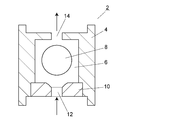
- the check valve 2 includes a casing 4, a sphere 8 and a valve seat 10.
- a valve space 6 is provided inside the casing 4, and a sphere 8 is movably accommodated in the valve space 6.
- the valve seat 10 is for seating the sphere 8 and is mounted on the casing 4.
- the valve seat 10 is provided with a through hole 12 that forms a liquid inlet, and the sphere 8 is seated on the edge of the through 12 to close the through hole 12, thereby closing the valve.
- a fluid outlet 14 is provided on the wall of the casing 4 on the side opposite to the valve seat 10.
- the sphere 8 is made of ruby, for example, and has a diameter of about 1.5 mm.
- the valve seat 10 is a member made of, for example, sapphire and having a cylindrical shape with an outer diameter of about 3 mm and a thickness of about 1 mm.
- the inner diameter of the through hole 12 is, for example, about 1 mm (radius RH is about 0.5 mm).
- valve seat 10 will be described with reference to FIGS. 2A, 2B, 2C, and 3.
- FIG. 2A, 2B, 2C, and 3
- a through hole 12 is provided in the center of the valve seat 10.
- An arc-shaped first slope 16, second slope 18, and third slope 20 are provided in this order from the outside at the edge of the spherical body 8 side opening of the through hole 12.
- the first inclined surface 16, the second inclined surface 18 and the third inclined surface 20 are concave spherical surfaces which are coaxial with the through hole 12.
- the first slope 16, the second slope 18 and the third slope 20 have different radii of curvature, the second slope 18 is provided continuously inside the first slope 16, and the third slope 20 is the second slope 18. It is continuously provided inside.
- a convex corner portion 17 is formed in an annular shape at a boundary portion between the first slope 16 and the second slope 18, and a convex corner portion 19 is formed at a boundary portion between the second slope 18 and the third slope 20. It is formed in an annular shape.
- the radius of curvature of the first slope 16 is R 1
- the radius of curvature of the second slope 18 is R 2
- the radius of curvature of the third slope 20 is R 3
- the radius of the sphere 8 is R B.
- the radius of the through hole 12 when the R H, R 1> R B > R 2> R 3> relation R H is established.
- the sphere 8 and the valve seat 10 are in line contact at the convex corner portion 17. Since the contact between the sphere 8 and the valve seat 10 is a line contact at the convex corner 17, the occurrence of the biting phenomenon between the sphere 8 and the valve seat 10 is prevented.
- the gap between the sphere 8 and the third inclined surface 20 is wider than the gap between the sphere 8 and the second slope 20.
- a wide gap is secured on the inner side of the convex corner 17 which is a line contact portion between the sphere 8 and the valve seat 10.
- the radius of curvature R 2 of the second slope 18 is further reduced, for example, to widen the gap between the sphere 8 and the second slope 18, thereby introducing impurities into the gap. It is also conceivable to prevent the accumulation of slag. However, if it does so, the convex corner 17 in line contact with the sphere 8 will be sharpened, and the surface of the sphere 8 may be scratched or the convex corner 17 may be missing.
- the angle formed by the convex corner portion 17 is preferably 155 ° or more.
- the angle formed by the convex corner portion 19 that does not contact the sphere 8 may be any angle as long as it can form a gap that does not cause accumulation of impurities or the like.
- the first inclined surface 16, the second inclined surface 18, and the third inclined surface 20 are concave spherical surfaces, which are selected from the ease of high-precision machining in the manufacturing stage. That is, since the concave spherical surface processing can easily control the center accuracy, it is easy to form the first slope 16, the second slope 18, and the third slope 20.
- the first inclined surface 16, the second inclined surface 18, and the third inclined surface 20 do not necessarily need to be concave spherical surfaces.
- the first slope 16 and the second slope 18 may be concave spherical surfaces
- the third slope 20 may be a tapered surface having a non-curved cross section.
- the first inclined surface 16, the second inclined surface 18, and the third inclined surface 20 may all be tapered surfaces having a non-curved cross-sectional shape.
- the non-curved tapered surface of the cross-sectional shape can be formed by pressing a conical drill tooth.
- valve seat 10 described with reference to FIGS. 2A, 2B, 2C, and 3 will be described in the order of steps with reference to FIGS.
- a through-hole 12 having a diameter R H (for example, 0.5 mm) is formed in the center of the disk-shaped base material to be the valve seat 10 in the thickness direction of the disk by known machining (FIGS. 5A and 5B). )).
- the bearing steel ball 22 having a radius R 1 is pressed against the opening of the through hole 12 of the valve seat 10 while rotating it (FIG. 5C), thereby forming an annular concave spherical surface on the edge of the through hole 12.
- One slope 16 is formed (FIG. 5D).
- the radius R 1 of the bearing steel ball 22 only needs to be larger than the radius R B (for example, 0.75 mm) of the sphere 8, and there is no particular limitation on the upper limit. However, it is necessary to make the depth so that a second slope 18 and a third slope 20 described later can be further formed inside the first slope 16, and the casing 4 is fixed to the outer periphery of the valve seat 10.
- R 1 is suitably 2.0 to 5.0 mm.
- the JIS standard defines bearing steel balls having different sizes in 0.5 mm increments within this range, and it is possible to form a concave spherical surface using bearing steel balls having a high degree of sphericity.
- the bearing steel ball 24 having a radius R 2 is pressed against the opening of the through hole 12 of the valve seat 10 in which the first slope 16 is formed (FIG. 6 (E)).
- a second slope 18 that is an annular concave spherical surface is formed inside 16 (FIG. 6F). Since the radius R 2 of the bearing steel ball 24 is smaller than the radius R 1 of the bearing steel ball 22, the roundness at the boundary between the first slope 16 and the second slope 18 is different due to the difference between R 1 and R 2.
- An annular convex corner 17 having a high height is formed.
- the bearing steel ball 26 having a radius R 3 is pressed against the opening of the through hole 12 of the valve seat 10 in which the second slope 18 is formed (FIG. 6 (G)), whereby the second slope 18 A third inclined surface 20 that is an annular concave spherical surface is formed on the inner side (FIG. 6H). Since the radius R 3 of the bearing steel ball 26 is smaller than the radius R 2 of the bearing steel ball 24, a convex corner is formed at the boundary between the second slope 18 and the third slope 20 due to the difference between R 2 and R 3. 19 is formed.
- the size of the second slope 18 remaining on the outside of the third slope 20 (the distance between the convex corner 17 and the convex corner 19) is 0.026 mm or less. It is preferable to process. Since the gap between the sphere 8 and the second inclined surface 18 is narrow, if the second inclined surface 18 remains large, impurities and the like accumulate between the sphere 8 and the second inclined surface 18, and the sphere 8 and the valve seat 10. This is because contact with can be surface contact.
- the liquid feeding device 30 reciprocates a plunger 36 in one direction (left and right in the drawing) in a pump chamber 34 provided inside a pump head 32, and sucks liquid into the pump chamber 34 and the pump chamber 34.
- the liquid is fed by continuously discharging the liquid from the tank.
- An eccentric cam 44 that rotates about a shaft 46 is disposed on the base end side (right side in the drawing) of the pump head 32.
- a cross head 40 is movably attached to the base end portion of the pump head 32.
- the cross head 40 holds the proximal end portion of the plunger 36 and includes a cam follower 42 on the opposite side of the plunger 36.
- a spring 48 (for example, a coil spring) that biases the cross head 40 toward the eccentric cam 44 is disposed inside the pump head 32.
- the cam follower 42 always follows the circumferential surface of the eccentric cam 44, and the cross head 40 reciprocates in one direction (left and right in the figure) by the rotation of the eccentric cam 44.
- the tip of the plunger 36 is inserted into the pump chamber 34. Since the plunger 36 is held by the cross head 40, it reciprocates in one direction together with the cross head 40 by the rotation of the eccentric cam 44.
- a ring-shaped sealing member 38 is provided at a portion of the pump chamber 34 where the plunger 36 is inserted.
- the seal member 38 is fixed to the pump head 32. The seal member 38 holds the outer peripheral surface of the plunger 36 and prevents liquid leakage from the pump chamber 32 to the crosshead 40 side.
- Check valves 2 a and 2 b are attached to the pump head 32.
- the check valve 2 a is attached to an inlet for allowing liquid to flow into the pump chamber 34
- the check valve 2 b is attached to an outlet for allowing liquid to flow out of the pump chamber 34.
- the check valves 2a and 2b the check valve 2 described in the above embodiment is used.
- the check valve 2a is connected to a flow path that leads to a container that stores the liquid to be sent, and the check valve 2b is a flow path that sends the liquid (for example, a liquid chromatograph). Are connected.
- a liquid feeding device 30, a sample injection unit 54, an analysis column 56, and a detector 58 are provided on the analysis flow path 50.
- the liquid feeding device 30 is the liquid feeding device shown in FIG.
- the liquid feeding device 30 sends the mobile phase contained in the mobile phase container 52 through the analysis flow path 50.
- a sample injection unit 54 is provided on the downstream side of the liquid feeding device 30.
- the sample injection unit 54 is an autosampler that automatically collects a sample and injects it into the analysis flow path 50.
- An analysis column 56 for separating the sample for each component is provided on the downstream side of the sample injection unit 54.
- a detector 58 for detecting components separated by the analysis column 56 is provided further downstream of the analysis column 56.
- the sample injected into the analysis channel 50 by the sample injection unit 54 flows downstream in the analysis channel 50 together with the mobile phase fed by the liquid feeding device 30 and is introduced into the analysis column 56.
- the components in the sample introduced into the analysis column 56 are separated by the difference in mobility in the analysis column 56, and are introduced into the detector 58 in order from components having the highest mobility and detected. By analyzing the detection signal obtained by the detector 58, the components in the sample are identified and quantified.
Landscapes
- Engineering & Computer Science (AREA)
- General Engineering & Computer Science (AREA)
- Mechanical Engineering (AREA)
- Physics & Mathematics (AREA)
- Health & Medical Sciences (AREA)
- Life Sciences & Earth Sciences (AREA)
- Chemical & Material Sciences (AREA)
- Analytical Chemistry (AREA)
- Biochemistry (AREA)
- General Health & Medical Sciences (AREA)
- General Physics & Mathematics (AREA)
- Immunology (AREA)
- Pathology (AREA)
- Check Valves (AREA)
Abstract
L'invention concerne un clapet antiretour comportant : une sphère ; un espace de clapet qui reçoit la sphère ; et un siège de clapet qui possède en son sein un orifice traversant, l'orifice traversant formant un passage d'écoulement pour permettre à un liquide de s'écouler dans l'espace de clapet, et sur lequel la sphère repose de façon à fermer l'ouverture de sortie de l'orifice traversant. Le siège de clapet comporte : une première surface inclinée qui est formée de façon circulaire annulaire sur la surface latérale interne de l'orifice traversant ; une deuxième surface inclinée qui est formée de façon circulaire annulaire sur l'intérieur de la première surface inclinée de façon à former de façon circulaire annulaire un coin saillant à angle obtus au niveau de la limite entre la deuxième surface inclinée et la première surface inclinée ; et une troisième surface inclinée qui est formée sur l'intérieur de la deuxième surface inclinée de façon à former de façon circulaire annulaire un coin saillant au niveau de la limite entre la troisième surface inclinée et la deuxième surface inclinée. Les tailles de la sphère et du siège de clapet sont définies de sorte que la sphère est en contact linéaire avec le coin saillant au niveau de la limite entre la première surface inclinée et la deuxième surface inclinée.
Priority Applications (2)
| Application Number | Priority Date | Filing Date | Title |
|---|---|---|---|
| PCT/JP2013/074043 WO2015033432A1 (fr) | 2013-09-06 | 2013-09-06 | Clapet antiretour, procédé de fabrication de celui-ci, dispositif d'alimentation de liquide doté dudit clapet antiretour, et chromatographe liquide doté dudit dispositif d'alimentation de liquide |
| JP2015535229A JP6090457B2 (ja) | 2013-09-06 | 2013-09-06 | 逆止弁とその製造方法、その逆止弁を備えた送液装置及びその送液装置を備えた液体クロマトグラフ |
Applications Claiming Priority (1)
| Application Number | Priority Date | Filing Date | Title |
|---|---|---|---|
| PCT/JP2013/074043 WO2015033432A1 (fr) | 2013-09-06 | 2013-09-06 | Clapet antiretour, procédé de fabrication de celui-ci, dispositif d'alimentation de liquide doté dudit clapet antiretour, et chromatographe liquide doté dudit dispositif d'alimentation de liquide |
Publications (1)
| Publication Number | Publication Date |
|---|---|
| WO2015033432A1 true WO2015033432A1 (fr) | 2015-03-12 |
Family
ID=52627939
Family Applications (1)
| Application Number | Title | Priority Date | Filing Date |
|---|---|---|---|
| PCT/JP2013/074043 Ceased WO2015033432A1 (fr) | 2013-09-06 | 2013-09-06 | Clapet antiretour, procédé de fabrication de celui-ci, dispositif d'alimentation de liquide doté dudit clapet antiretour, et chromatographe liquide doté dudit dispositif d'alimentation de liquide |
Country Status (2)
| Country | Link |
|---|---|
| JP (1) | JP6090457B2 (fr) |
| WO (1) | WO2015033432A1 (fr) |
Cited By (5)
| Publication number | Priority date | Publication date | Assignee | Title |
|---|---|---|---|---|
| JP2017061864A (ja) * | 2015-09-24 | 2017-03-30 | アイシン精機株式会社 | 可変オイルポンプ |
| JP2019112984A (ja) * | 2017-12-22 | 2019-07-11 | 日立オートモティブシステムズ株式会社 | 燃料噴射弁 |
| WO2020239565A1 (fr) * | 2019-05-29 | 2020-12-03 | Robert Bosch Gmbh | Soupape de distribution à siège et procédé de fabrication d'un corps de siège de soupape d'une soupape de distribution à siège |
| CN114174670A (zh) * | 2019-07-19 | 2022-03-11 | 罗伯特·博世有限公司 | 燃料高压泵 |
| DE102023117166A1 (de) * | 2023-06-29 | 2025-01-02 | TESTA Analytical Solutions e.K. | Ventil mit einer Durchflussrichtung |
Citations (4)
| Publication number | Priority date | Publication date | Assignee | Title |
|---|---|---|---|---|
| FR981999A (fr) * | 1943-05-28 | 1951-06-01 | Citroen Sa Andre | Dispositifs obturateurs et leur procédé de fabrication |
| JPH109151A (ja) * | 1996-06-26 | 1998-01-13 | Nok Corp | 逆止弁付ピストン |
| JP2009103554A (ja) * | 2007-10-23 | 2009-05-14 | Shimadzu Corp | 逆止弁とそれを用いた送液装置、及び該逆止弁の製造方法 |
| US20110042605A1 (en) * | 2007-01-10 | 2011-02-24 | Fritz Gyger | Micro-valve |
-
2013
- 2013-09-06 WO PCT/JP2013/074043 patent/WO2015033432A1/fr not_active Ceased
- 2013-09-06 JP JP2015535229A patent/JP6090457B2/ja active Active
Patent Citations (4)
| Publication number | Priority date | Publication date | Assignee | Title |
|---|---|---|---|---|
| FR981999A (fr) * | 1943-05-28 | 1951-06-01 | Citroen Sa Andre | Dispositifs obturateurs et leur procédé de fabrication |
| JPH109151A (ja) * | 1996-06-26 | 1998-01-13 | Nok Corp | 逆止弁付ピストン |
| US20110042605A1 (en) * | 2007-01-10 | 2011-02-24 | Fritz Gyger | Micro-valve |
| JP2009103554A (ja) * | 2007-10-23 | 2009-05-14 | Shimadzu Corp | 逆止弁とそれを用いた送液装置、及び該逆止弁の製造方法 |
Cited By (8)
| Publication number | Priority date | Publication date | Assignee | Title |
|---|---|---|---|---|
| JP2017061864A (ja) * | 2015-09-24 | 2017-03-30 | アイシン精機株式会社 | 可変オイルポンプ |
| WO2017051646A1 (fr) * | 2015-09-24 | 2017-03-30 | アイシン精機株式会社 | Pompe à huile variable |
| JP2019112984A (ja) * | 2017-12-22 | 2019-07-11 | 日立オートモティブシステムズ株式会社 | 燃料噴射弁 |
| WO2020239565A1 (fr) * | 2019-05-29 | 2020-12-03 | Robert Bosch Gmbh | Soupape de distribution à siège et procédé de fabrication d'un corps de siège de soupape d'une soupape de distribution à siège |
| CN114174670A (zh) * | 2019-07-19 | 2022-03-11 | 罗伯特·博世有限公司 | 燃料高压泵 |
| JP2022542545A (ja) * | 2019-07-19 | 2022-10-05 | ローベルト ボツシユ ゲゼルシヤフト ミツト ベシユレンクテル ハフツング | 燃料高圧ポンプ |
| DE102023117166A1 (de) * | 2023-06-29 | 2025-01-02 | TESTA Analytical Solutions e.K. | Ventil mit einer Durchflussrichtung |
| DE102023117166B4 (de) * | 2023-06-29 | 2025-04-24 | TESTA Analytical Solutions e.K. | Ventil mit einer Durchflussrichtung |
Also Published As
| Publication number | Publication date |
|---|---|
| JP6090457B2 (ja) | 2017-03-08 |
| JPWO2015033432A1 (ja) | 2017-03-02 |
Similar Documents
| Publication | Publication Date | Title |
|---|---|---|
| JP4831049B2 (ja) | 逆止弁とそれを用いた送液装置、及び該逆止弁の製造方法 | |
| JP6090457B2 (ja) | 逆止弁とその製造方法、その逆止弁を備えた送液装置及びその送液装置を備えた液体クロマトグラフ | |
| US9689384B2 (en) | Liquid feed pump and liquid chromatograph | |
| US7837235B2 (en) | Device for clamping a fluidic component | |
| KR101442940B1 (ko) | 볼 밸브 | |
| CN106414192B (zh) | 具有容纳元件的排出阀 | |
| US20170009723A1 (en) | Piston Fuel Pump for an Internal Combustion Engine | |
| JP6673014B2 (ja) | バックアップリング及びそのバックアップリングを用いた送液ポンプ | |
| US20110318205A1 (en) | Solvent delivery pump | |
| US20050214139A1 (en) | Liquid delivery pump for liquid chromatograph | |
| JP2008180088A (ja) | 送液ポンプ | |
| JP5440706B2 (ja) | 逆止弁及び送液ポンプ | |
| JP2014504348A (ja) | バルブ、特に油圧ピストンポンプの排出バルブ | |
| US20040108000A1 (en) | Ultrahigh-pressure check valve | |
| US20180252210A1 (en) | Compact Ultrahigh Pressure Dynamic Seal Assembly With Pressure Activating Backup Ring | |
| CN212508780U (zh) | 一种具有自定位功能的计量泵氧化陶瓷柱塞及其安装结构 | |
| US20070215217A1 (en) | Outlet check valve | |
| JP6421701B2 (ja) | 高圧ポンプ | |
| US20180238468A1 (en) | Sealing system of a device for allowing the passage of a medium, in particular in the high pressure range | |
| US20120031264A1 (en) | Solvent delivery pump | |
| JP2005188379A (ja) | 逆止弁及びその逆止弁を備える燃料噴射ポンプ | |
| CN106257055B (zh) | 送液泵 | |
| CN111550397B (zh) | 一种具有自定位功能的计量泵氧化陶瓷柱塞 | |
| JP5610092B2 (ja) | 送液ポンプ及び液体クロマトグラフ | |
| JP3118651U (ja) | 液体クロマトグラフ用送液ポンプ |
Legal Events
| Date | Code | Title | Description |
|---|---|---|---|
| 121 | Ep: the epo has been informed by wipo that ep was designated in this application |
Ref document number: 13893080 Country of ref document: EP Kind code of ref document: A1 |
|
| ENP | Entry into the national phase |
Ref document number: 2015535229 Country of ref document: JP Kind code of ref document: A |
|
| NENP | Non-entry into the national phase |
Ref country code: DE |
|
| 122 | Ep: pct application non-entry in european phase |
Ref document number: 13893080 Country of ref document: EP Kind code of ref document: A1 |