WO2015040846A1 - 車椅子及び合体ベッド - Google Patents
車椅子及び合体ベッド Download PDFInfo
- Publication number
- WO2015040846A1 WO2015040846A1 PCT/JP2014/004736 JP2014004736W WO2015040846A1 WO 2015040846 A1 WO2015040846 A1 WO 2015040846A1 JP 2014004736 W JP2014004736 W JP 2014004736W WO 2015040846 A1 WO2015040846 A1 WO 2015040846A1
- Authority
- WO
- WIPO (PCT)
- Prior art keywords
- link
- wheelchair
- bed
- roller
- combined
- Prior art date
- Legal status (The legal status is an assumption and is not a legal conclusion. Google has not performed a legal analysis and makes no representation as to the accuracy of the status listed.)
- Ceased
Links
Images




Classifications
-
- A—HUMAN NECESSITIES
- A61—MEDICAL OR VETERINARY SCIENCE; HYGIENE
- A61G—TRANSPORT, PERSONAL CONVEYANCES, OR ACCOMMODATION SPECIALLY ADAPTED FOR PATIENTS OR DISABLED PERSONS; OPERATING TABLES OR CHAIRS; CHAIRS FOR DENTISTRY; FUNERAL DEVICES
- A61G7/00—Beds specially adapted for nursing; Devices for lifting patients or disabled persons
- A61G7/10—Devices for lifting patients or disabled persons, e.g. special adaptations of hoists thereto
- A61G7/16—Devices for lifting patients or disabled persons, e.g. special adaptations of hoists thereto converting a lying surface into a chair
-
- A—HUMAN NECESSITIES
- A61—MEDICAL OR VETERINARY SCIENCE; HYGIENE
- A61G—TRANSPORT, PERSONAL CONVEYANCES, OR ACCOMMODATION SPECIALLY ADAPTED FOR PATIENTS OR DISABLED PERSONS; OPERATING TABLES OR CHAIRS; CHAIRS FOR DENTISTRY; FUNERAL DEVICES
- A61G1/00—Stretchers
- A61G1/017—Stretchers convertible into chairs
-
- A—HUMAN NECESSITIES
- A61—MEDICAL OR VETERINARY SCIENCE; HYGIENE
- A61G—TRANSPORT, PERSONAL CONVEYANCES, OR ACCOMMODATION SPECIALLY ADAPTED FOR PATIENTS OR DISABLED PERSONS; OPERATING TABLES OR CHAIRS; CHAIRS FOR DENTISTRY; FUNERAL DEVICES
- A61G5/00—Chairs or personal conveyances specially adapted for patients or disabled persons, e.g. wheelchairs
- A61G5/006—Chairs or personal conveyances specially adapted for patients or disabled persons, e.g. wheelchairs convertible to stretchers or beds
-
- A—HUMAN NECESSITIES
- A61—MEDICAL OR VETERINARY SCIENCE; HYGIENE
- A61G—TRANSPORT, PERSONAL CONVEYANCES, OR ACCOMMODATION SPECIALLY ADAPTED FOR PATIENTS OR DISABLED PERSONS; OPERATING TABLES OR CHAIRS; CHAIRS FOR DENTISTRY; FUNERAL DEVICES
- A61G5/00—Chairs or personal conveyances specially adapted for patients or disabled persons, e.g. wheelchairs
- A61G5/08—Chairs or personal conveyances specially adapted for patients or disabled persons, e.g. wheelchairs foldable
-
- A—HUMAN NECESSITIES
- A61—MEDICAL OR VETERINARY SCIENCE; HYGIENE
- A61G—TRANSPORT, PERSONAL CONVEYANCES, OR ACCOMMODATION SPECIALLY ADAPTED FOR PATIENTS OR DISABLED PERSONS; OPERATING TABLES OR CHAIRS; CHAIRS FOR DENTISTRY; FUNERAL DEVICES
- A61G5/00—Chairs or personal conveyances specially adapted for patients or disabled persons, e.g. wheelchairs
- A61G5/10—Parts, details or accessories
- A61G5/1056—Arrangements for adjusting the seat
- A61G5/1067—Arrangements for adjusting the seat adjusting the backrest relative to the seat portion
-
- A—HUMAN NECESSITIES
- A61—MEDICAL OR VETERINARY SCIENCE; HYGIENE
- A61G—TRANSPORT, PERSONAL CONVEYANCES, OR ACCOMMODATION SPECIALLY ADAPTED FOR PATIENTS OR DISABLED PERSONS; OPERATING TABLES OR CHAIRS; CHAIRS FOR DENTISTRY; FUNERAL DEVICES
- A61G7/00—Beds specially adapted for nursing; Devices for lifting patients or disabled persons
- A61G7/05—Parts, details or accessories of beds
- A61G7/053—Aids for getting into, or out of, bed, e.g. steps, chairs, cane-like supports
-
- A—HUMAN NECESSITIES
- A61—MEDICAL OR VETERINARY SCIENCE; HYGIENE
- A61G—TRANSPORT, PERSONAL CONVEYANCES, OR ACCOMMODATION SPECIALLY ADAPTED FOR PATIENTS OR DISABLED PERSONS; OPERATING TABLES OR CHAIRS; CHAIRS FOR DENTISTRY; FUNERAL DEVICES
- A61G7/00—Beds specially adapted for nursing; Devices for lifting patients or disabled persons
- A61G7/10—Devices for lifting patients or disabled persons, e.g. special adaptations of hoists thereto
- A61G7/16—Devices for lifting patients or disabled persons, e.g. special adaptations of hoists thereto converting a lying surface into a chair
- A61G7/165—Chair detachable from bed
Definitions
- the present invention relates to a wheelchair and a combined bed that are combined into a part of the bed.
- FIG. 8 and 9 show the wheelchair 6 of Patent Document 1.
- FIG. The wheelchair 6 is in a flat posture by tilting the back portion 7a so that all of the bottom portion 7b, the calf portion 7c, and the footrest portion 7d connected by the interlocking link 8 are on the same horizontal plane.
- FIG. 9 is a side view of the wheelchair 6 in a flat posture.
- the caregiver can change the posture of the wheelchair 6 from the chair posture to the flat posture by using the interlocking link 8.
- Such a reclining wheelchair 6 may be applied as a wheelchair part to form a combined bed.
- This invention solves such a subject and it aims at providing the wheelchair and united bed which are easy to unite to a bed.
- a wheelchair according to one aspect of the present invention includes a wheelchair bottom portion configured by connecting a first bottom, a fifth bottom, a second bottom, a third bottom, and a fourth bottom; A first link supporting the first bottom; A second link for supporting the second bottom; A third link for supporting the third bottom; A fourth link supporting the fourth bottom; A first base for supporting the fifth bottom; A first drive link that moves the second link and the third link in conjunction with each other; A first connection link that connects the first link and the first drive link, and moves the first drive link in conjunction with movement of the first link; The first drive link is slidable with respect to the second link with a first roller disposed at one end thereof, and a second roller disposed at the other end is slidable with respect to the third link. It is characterized by being.
- the union bed concerning another aspect of this invention is the bed comprised by connecting the said wheelchair, the 7th bottom, the 8th bottom, the 9th bottom, and the 10th bottom.
- the bed portion includes an elevating unit that is positioned below the third link and moves up and down the ninth bottom when combined.
- FIG. 1A is a side view of a flat posture of a wheelchair in the first embodiment of the present invention
- FIG. 1B is a side view of the chair posture of the wheelchair in the first embodiment of the present invention
- FIG. 2 is a perspective view of the first drive link in the first embodiment.
- FIG. 3A is a partial perspective view of the first link mechanism in the first embodiment in a flat posture
- FIG. 3B is a partial side view of the first link mechanism in the first embodiment when in a flat posture
- FIG. 3C is a partial side view of the first link mechanism in the first embodiment when the chair posture is set
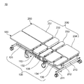
- FIG. 4 is a perspective view of the combined bed in the first embodiment.
- FIG. 5 is a side view of the combined state of the combined bed in the first embodiment, FIG.
- FIG. 6 is a perspective view of the combined state of the combined bed in the first embodiment
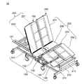
- FIG. 7 is a perspective view of the knee-raising posture and the back-raising posture of the combined bed in the first embodiment
- FIG. 8 is a side view of the chair posture of the wheelchair of Patent Document 1
- FIG. 9 is a side view of the flat posture of the wheelchair of Patent Document 1.
- FIG. 1A is a side view of a flat posture of a wheelchair according to the first embodiment of the present invention.
- FIG. 1B is a side view of a chair posture of a wheelchair.
- the chair posture is a chair-like posture in which the thigh portion is inclined upward and the footrest portion is configured, as shown in FIG. 1B.
- the wheelchair 100 includes a wheelchair bottom portion 130 (see FIG. 4), a wheelchair link portion 120 (see FIG. 4), and a first base portion 110.
- the wheelchair bottom portion 130 is arranged from the rear end to the front end of the wheelchair 100, respectively, a first bottom 131, a fifth bottom 132, a second bottom 133, a third bottom 134, A fourth bottom 135 is formed.
- wheelchair bottom part 130 is an example of the 6th bottom which is the bottom of the whole wheelchair.
- the wheelchair link unit 120 is an example of a fifth link that is an entire link of the wheelchair.
- the first base portion 110 is an example of a wheelchair base portion that supports the wheelchair bottom portion 130.
- the first bottom 131 is an example of a wheelchair back bottom that is a bottom on the back side of the wheelchair.
- the fifth bottom 132 is an example of a wheelchair waist bottom that is a waist-side bottom of the wheelchair.
- the second bottom 133 is an example of a wheelchair thigh bottom that is a thigh-side bottom of the wheelchair.
- the third bottom 134 is an example of a wheelchair thigh shin bottom that is a bottom on the thigh shin side of the wheelchair.
- the fourth bottom 135 is an example of a wheelchair foot bottom that is a foot-side bottom of the wheelchair.
- the wheelchair link portion 120 is arranged to be biased to one side (left side in FIG. 4) in the width direction of the wheelchair 100 with respect to the wheelchair bottom portion 130.
- the wheelchair bottom part 130 is supported by the bed link part 220 from below when the bed part 200 and the wheelchair 100 are combined.
- the bed link unit 220 is an example of a sixth link that is an entire link of the bed unit 200.
- the wheelchair link unit 120 includes a first link 121, a second link 123, a third link 124, and a fourth link 125, which are arranged from the rear end to the front end of the wheelchair 100, respectively. Composed.
- the first link 121 is an example of a wheelchair back link 121 that is a link on the back side of the wheelchair.
- the second link 123 is an example of a wheelchair thigh link that is a link on the thigh side of the wheelchair.
- the third link 124 is an example of a wheelchair calf link that is a link on the calf side of the wheelchair.
- the fourth link 125 is an example of a wheelchair foot link that is a link on the foot side of the wheelchair.
- the first link 121 is composed of a substantially T-shaped member having a second member 121b and a first member 121a fixed so as to extend obliquely from the center of the second member 121b.
- An end portion (rear end) of the first member 121a is rotatably connected to an intermediate portion in the longitudinal direction of the back surface of the first bottom 131.
- One end (upper end) of the second member 121b is rotatably connected to the rear end of the third frame 111.
- the other end (lower end) of the second member 121b is rotatably connected to the front end (rear end) of a drive rod 113a of a linear actuator 113 described later.
- the rear end of the first connecting link 126 is rotatably connected to the intermediate portion of the second member 121b.
- the third frame 111 is an example of a wheelchair frame that is a wheelchair frame.
- the first connection link 126 is an example of a wheelchair connection link that connects a plurality of links of the wheelchair.
- the rear end of the second link 123 is rotatably connected to the front end of the third frame 111, and the front end thereof is rotatably connected to the rear end of the third link 124.
- the rear end of the third link 124 is rotatably connected to the front end of the second link 123, and the front end is rotatably connected to the rear end of the fourth link 125.
- the rear end of the fourth link 125 is rotatably connected to the front end of the third link 124.
- the first base portion 110 includes a third frame 111 and a plurality of front and rear wheels 112 that are rotatably disposed at the lower end of the third frame 111.
- the first link 121 supports the first bottom 131.
- the second link 123 supports the second bottom 133.
- the third link 124 supports the third bottom 134.
- the fourth link 125 supports the fourth bottom 135.
- the 1st base part 110 is supporting the 5th bottom 132 from the downward direction.
- first bottom 131, the fifth bottom 132, the second bottom 133, the third bottom 134, and the fourth bottom 135 constitute a wheelchair bottom portion 130 in which adjacent bottoms are flexibly connected to each other. It is.
- the second link 123, the third link 124, and the fourth link 125 are configured such that adjacent links are connected to each other so as to be bendable, thereby forming the wheelchair link unit 120.
- frame 111 has connected the 1st link 121 and the 2nd link 123 so that bending is possible.
- the fifth bottom 132 and the second bottom 133 constitute a twelfth bottom.
- the twelfth bottom is an example of a wheelchair seat bottom that is the bottom of the seat surface portion of the wheelchair.
- the wheelchair link unit 120 of the wheelchair 100 includes a first connection link 126, a first drive link 127, and a second drive link 128.
- the first drive link 127 which will be described in detail later, is a wheelchair thigh- calf link that drives the second link 123, which is a link on the thigh side of the wheelchair, and the third link 124, which is a link on the calf side, of the wheelchair. It is an example.
- the second drive link 128 is an example of a wheelchair foot drive link that drives the fourth link 125 on the foot side of the wheelchair.
- Each link part of each link or a link and another member is rotatable.
- the first connection link 126 connects the first link 121 and the first drive link 127.
- the first drive link 127 is rotatably connected to the front end of the third frame 111.
- the second drive link 128 connects the second link 123 and the fourth link 125.
- the second drive link 128 causes the second link 123 and the third link 124 to be positioned along the horizontal direction when the wheelchair 100 is in a flat posture, and bend each other when the chair is in a chair posture.
- the first connection link 126 pulls the first drive link 127 to rotate it clockwise in FIG. 1A, and the second link 123 and the third link 124 are illustrated.
- the posture is as shown in 1B.
- the first connecting link 126 pushes the first driving link 127 to rotate counterclockwise in FIG. 1A, and the second link 123 and the third link 124. And become horizontal.
- a mechanism constituted by the link 128 is defined as a first link mechanism which is an example of a wheelchair posture forming link mechanism for forming a wheelchair posture.
- the wheelchair 100 includes a linear motion actuator 113 that extends and retracts as the drive rod 113a advances and retreats with respect to the casing 113b.
- One end (front end) of the linear motion actuator 113 is flexibly connected to the third frame 111, and the other end (rear end) is flexibly connected to the first link 121.
- the wheelchair 100 is deformed from a flat posture to a chair posture via a first link mechanism such as the first link 121.
- the wheelchair 100 is deformed from the chair posture to the flat posture via the first link mechanism such as the first link 121.
- linear actuator 113 is an example of a linear mechanism.
- a linear motion mechanism other than the linear motion actuator for example, there is a linear motion structure using a gas spring.
- the linear actuator 113 is disposed so as to connect the third frame 111 and the first drive link 127, whereby the first bottom 131 and the third bottom 134 are separately provided. It may be possible to operate.
- FIG. 2 is a perspective view of the first drive link 127 in the first embodiment.
- FIG. 3A is a partial perspective view of the first link mechanism in the first embodiment when in a flat posture.
- FIG. 3B is a partial side view of the first link mechanism in a flat posture.
- FIG. 3C is a partial side view of the first link mechanism in the chair posture.
- the first roller 127a, the second roller 127b, and the first frame 127c are shown so that the configuration and operation can be easily understood.
- the operation of the first drive link 127 will be described with reference to FIGS. 2 to 3C.
- the first drive link 127 includes a pair of first rollers 127a, a pair of second rollers 127b, a first frame 127c, and a second frame 127d.
- the first roller 127a is an example of a thigh sliding roller that slides in the rail portion of the second link 123 on the thigh side of the wheelchair.
- the second roller 127b is an example of a calf sliding roller that slides in the rail portion of the third link 124 on the calf side of the wheelchair.
- the first frame 127c is a long columnar member, and a pair of first rollers 127a is arranged at one end (rear end) thereof so as to be non-rotatable or rotatable, and a pair of second rollers at the other end (front end). 127b is arranged so as not to rotate or to rotate freely.
- the second frame 127d is fixed so as to protrude at an intermediate position between the first roller 127a and the second roller 127b. That is, the first frame 127c and the second frame 127d are arranged to form a Y-shaped member.
- a first first connection hinge 127e to which the front end of the first connection link 126 is rotatably connected is disposed at one end (lower end) of the second frame 127d opposite to the first frame 127c.
- a frame hinge 127f is disposed between the first connection hinge 127e to which the first connection link 126 is connected and the first frame 127c.
- the frame hinge 127 f is rotatably connected to the rear end of the third frame 111 and serves as a forward / reverse rotation center of the first drive link 127 with respect to the third frame 111. Note that the first connecting hinge 127e and the frame hinge 127f are not illustrated, and are illustrated as through holes for the connecting hinge.
- the frame hinge 127f which is the rotation center of the first drive link 127, is closer to the first drive link 127 than the line connecting the rotation center of the first roller 127a and the rotation center of the second roller 127b. It is arranged on the first connection hinge 127 e side, which is a connection point with the first connection link 126.
- the wheelchair 100 has a rail section having a U-shaped cross-section (C-shape) in the middle portion of the second link 123 and the middle portion of the third link 124. 123a, 124a.
- the rail portions 123a and 124a are provided with a first roller 127a and a second roller 127b along the longitudinal direction between the back side start points (start point positions) Sa and Sb and the toe side end points (end point positions) Ea and Eb. Is configured to be slidable (movable forward and backward) in the rail portions 123a and 124a.
- the rail portions 123a and 124a are configured not to contact the first frame 127c when the first roller 127a and the second roller 127b slide.
- the first frame 127c is positioned along the horizontal direction
- the second link 123 and the third link 124 are positioned along the horizontal direction, respectively. .
- the second link 123 has a second connection hinge 123b rotatably connected to the front end of the third frame 111 at the rear end (the left end of the second link 123 in FIGS. 3A and 3B).
- 3rd connection hinge 123c rotatably connected with 5th connection hinge 124c of the rear end (left end of 3rd link 124 of FIG. 3A and 3B) of 3rd link 124 to the right end of 2nd link 123 of FIG. 3B.
- the third link 124 has a fourth connection hinge 124b rotatably connected to the fourth link 125 at the front end (the right end of the third link 124 in FIGS. 3A and 3B).
- the pair of second rollers 127b slides in the rail portion 124a from the starting point Sb on the back side to the end point Eb on the toe side and lowers to a position below the position in the flat posture.
- the wheelchair 100 is deformed into a chair posture as a result of the second link 123 being raised to a position above the position in the flat posture and the third link 124 being lowered to a position below the position in the flat posture.
- the operation is reversed. That is, when the drive rod 113a of the linear motion actuator 113 is retracted into the casing 113b and the first link 121 falls to deform the wheelchair 100 from the chair posture to the flat posture, the first drive link 127 is moved by the first connection link 126. It is pushed and rotates counterclockwise in FIG. 3C around the frame hinge 127f. As a result, as shown in FIG. 3B, the pair of first rollers 127a slides in the rail portion 123a from the end point Ea on the toe side to the start point Sa on the back side to a position below the position in the posture.
- the pair of second rollers 127b slide in the rail portion 124a from the end point Eb on the toe side to the start point Sb on the back side and rise to a position above the position in the chair posture.
- the first frame 127c is positioned along the horizontal direction
- the second link 123 and the third link 124 are positioned along the horizontal direction.
- the wheelchair 100 can greatly reduce the downward projection of the third link 124 from the wheelchair 100 in the flat posture as shown in FIGS. 2 to 3C.
- This uses the first drive link 127 having the first roller 127a and the second roller 127b, the second link 123, and the third link 124 to drive the second link 123 and the third link 124. This is because the region necessary for the mechanism is only the rail portions 123a and 124a for sliding the first roller 127a and the second roller 127b.
- the second link 123 and the third link 124 can be operated by one link, and the cost and weight can be reduced by reducing the number of parts.
- FIG. 4 is a perspective view of the combined bed 10 in the first embodiment.
- the combined bed 10 will be described with reference to FIG.
- the combined bed 10 is configured by combining the bed portion 200 and the wheelchair 100.
- the bed part 200 includes a bed bottom part 230, a bed link part 220 that supports the bed bottom part 230, and a second base part 210 to which the bed link part 220 is fixed.
- the bed bottom portion 230 is an example of an eleventh bottom that constitutes the entire bottom (floor surface portion) of the bed portion 200.
- the second base 210 is an example of a bed base that constitutes the base of the bed 200.
- the bed portion 200 has a lifting / lowering portion 212 that is positioned below a third link 124 (to be described later) at the time of uniting and lifts at least the ninth bottom 233.
- the bed bottom portion 230 connects the seventh bottom 231, the eighth bottom 232, the ninth bottom 233, and the tenth bottom 234, which are arranged along the longitudinal direction of the bed portion 200, so that the adjacent bottoms can be bent together.
- the seventh bottom 231 is an example of a bed back bottom that is a back bottom of the bed part 200.
- the eighth bottom 232 is an example of a bed waist bottom that is a waist-side bottom of the bed portion 200.
- the ninth bottom 233 is an example of a bed thigh bottom that is a thigh-side bottom of the bed portion 200.
- the tenth bottom 234 is an example of a bed foot bottom that is a foot-side bottom of the bed portion 200.
- the bed link unit 220 includes a seventh link 221 and an eighth link 223 arranged along the longitudinal direction of the bed unit 200.
- the seventh link 221 is an example of a bed spine link that is a link on the back side of the bed part 200 that supports the seventh bottom 231 and the like.
- the eighth link 223 is an example of a bed foot link that is a foot side link of the bed portion 200 that supports the ninth bottom 233, the tenth bottom 234, and the like.
- FIG. 4 only the exposed portion of the seventh link 221 other than the portion covered with the seventh bottom 231 (the region on the right half in the bed width direction in FIG. 4) is surrounded by a dotted line with a first dotted line. Shown as part.
- the first dotted line portion is covered with the first bottom 131 of the wheelchair 100 when the bed part 200 and the wheelchair 100 are combined, and the seventh bottom 231 and the first bottom 131 are integrally formed by the seventh link 221. It will be lifted and bent. Further, only the exposed portion of the eighth link 223 other than the portion covered with the ninth bottom 233 and the tenth bottom 234 (the region on the right half in the bed width direction in FIG. 4) is surrounded by a dotted line to be second. It is shown as a dotted line part.
- the second base part 210 includes a fourth frame 211, an elevating part 212, and a fifth frame 213.
- the fourth frame 211 is an example of a bed base frame that is a frame on the base side of the bed part 200.
- the fifth frame 213 is an example of a bed upper frame that is a frame on the upper side of the bed part 200.
- An elevating unit 212 is mounted on a fourth frame 211 that is movably installed on the floor with wheels or the like, and a fifth frame 213 is installed on the elevating unit 212.
- the fifth frame 213 is lifted with respect to the fourth frame 211 by the elevating unit 212, and the bed is raised and lowered. Further, the bed link part 220 and the bed bottom part 230 are fixed to the fifth frame 213.
- a concave portion 210 a is formed on the left side of the intermediate portion of the second base portion 210.
- the linear actuator 113 is driven to bring the wheelchair 100 into a flat posture. And the wheelchair 100 is moved so that the 1st base part 110 may enter into the recessed part 210a of the 2nd base part 210.
- FIG. After the first base portion 110 of the wheelchair 100 in the flat posture completely enters the concave portion 210a of the second base portion 210, the fifth frame 213 is raised by the elevating portion 212, and the bed link portion 220 and the bed bottom portion are raised. 230 and lift.
- the first base part 110 is supported and fixed by the fifth frame 213 from the lower side together with the bed link part 220 and the bed bottom part 230, and the union of the wheelchair 100 and the bed part 200 is completed.
- FIG. 5 is a side view of the combined bed 10 in the combined state in the first embodiment.
- an eighth link 223 and a fifth frame 213 are arranged below the third link 124.
- the third link protrudes downward as in the conventional case, it is necessary to avoid interference between the fifth frame 213 or the lifting unit 212 and the third link.
- the width of the fifth frame 213 is reduced, the width of the elevating part 212 is also reduced.
- the rigidity of the elevating part 212 is reduced. That is, since it is necessary to lift the wheelchair 100 particularly when united, the elevating unit 212 is required to be more rigid than a normal care bed.
- the third link 124 protrudes downward, it is difficult to ensure the rigidity. Become.
- the second link 123 and the third link 124 are positioned along the horizontal direction, and the rail portion 123a between the second link 123 and the third link 124 is provided. , 124a, the rollers 127a, 127b of the first drive link 127 are respectively positioned, and the first drive link 127 does not protrude at all below the third link 124. Therefore, by adopting the configuration of the first embodiment, there is no member protruding below the third link 124, and the combined bed 10 capable of minimizing the downward projection of the third link 124 can be configured. . Since the third link 124 does not protrude greatly downward in the flat posture, it is possible to avoid interference between the fifth frame 213 or the lifting unit 212 and the third link 124.
- FIG. 6 is a perspective view of the combined bed 10 in the combined state in the first embodiment.
- the wheelchair bottom part 130 and the bed bottom part 230 are united to form the bottom part as the combined bed 10.
- the joint portions that are flexibly connected between the bottoms are on the same straight line so that the wheelchair 100 can be bent as a bed when the wheelchair 100 is combined with the bed portion 200. It is in a line-up configuration.
- the bottom part comprised by the wheelchair bottom part 130 and the bed bottom part 230 can be made bendable.
- position can be taken.
- FIG. 7 is a perspective view of the combined bed 10 that takes the back-up posture and the knee-up posture.
- the wheelchair bottom part 130 is supported by the bed link part 220 together with the bed bottom part 230.
- the wheelchair bottom unit 130 and the bed bottom unit 230 integrally change the posture according to the change of the posture of the bed link unit 220.
- the first bottom 131 is the first link 121
- the second bottom 133 is the second link 123
- the third bottom 134 is the third link 124
- the fourth bottom 135 is the fourth link 125
- Each is supported by contact.
- the posture of the bed link unit 220 changes from the flat posture to the back-raising posture and the knee-raising posture after the combination, the link that supports the wheelchair bottom portion 130 is switched from the wheelchair link portion 120 to the bed link portion 220. Therefore, the postures of the wheelchair bottom part 130 and the bed bottom part 230 can be changed only by the bed link part 220.
- the combined bed 10 can take the same posture as a normal care bed when the wheelchair 100 and the bed part 200 are combined.
- the wheelchair and bed of the present invention are useful in ordinary homes, hospital facilities, or care facilities where people who need care are living.
Landscapes
- Health & Medical Sciences (AREA)
- Life Sciences & Earth Sciences (AREA)
- Animal Behavior & Ethology (AREA)
- General Health & Medical Sciences (AREA)
- Public Health (AREA)
- Veterinary Medicine (AREA)
- Nursing (AREA)
- Invalid Beds And Related Equipment (AREA)
Abstract
Description
前記第1ボトムを支持する第1リンクと、
前記第2ボトムを支持する第2リンクと、
前記第3ボトムを支持する第3リンクと、
前記第4ボトムを支持する第4リンクと、
前記第5ボトムを支持する第1基台部と、
前記第2リンク及び前記第3リンクを連動して動かす第1駆動リンクと、
前記第1リンクと前記第1駆動リンクとを連結して、前記第1リンクの動きに連動して前記第1駆動リンクを動かす第1連結リンクと、を備え、
前記第1駆動リンクは、その一端に配置された第1ローラが前記第2リンクに対して摺動可能であり、その他端に配置された第2ローラが前記第3リンクに対して摺動可能であることを特徴とする。
前記ベッド部は、合体時に前記第3リンクの下方に位置して前記第9ボトムを昇降させる昇降部を有することを特徴とする。
Claims (15)
- 第1ボトム、第5ボトム、第2ボトム、第3ボトム及び第4ボトムを連結して構成された車椅子ボトム部と、
前記第1ボトムを支持する第1リンクと、
前記第2ボトムを支持する第2リンクと、
前記第3ボトムを支持する第3リンクと、
前記第4ボトムを支持する第4リンクと、
前記第5ボトムを支持する第1基台部と、
前記第2リンク及び前記第3リンクを連動して動かす第1駆動リンクと、
前記第1リンクと前記第1駆動リンクとを連結して、前記第1リンクの動きに連動して前記第1駆動リンクを動かす第1連結リンクと、を備え、
前記第1駆動リンクは、その一端に配置された第1ローラが前記第2リンクに対して摺動可能であり、その他端に配置された第2ローラが前記第3リンクに対して摺動可能である、車椅子。 - 前記第2リンク及び前記第3リンクが、それぞれ断面C字状のレール部を有しており、
前記第1ローラは、前記第2リンクのレール部内を摺動し、前記第2ローラは、前記第3リンクのレール部内を摺動する、
請求項1に記載の車椅子。 - 前記第1ボトムは当該車椅子の背側のボトムであり、前記第2ボトムは当該車椅子の腿側のボトムであり、前記第3ボトムは当該車椅子の脹脛側のボトムであり、前記第4ボトムは当該車椅子の足側のボトムであり、前記第5ボトムは当該車椅子の腰側のボトムであり、
前記第1リンクは当該車椅子の背側のリンクであり、前記第2リンクは当該車椅子の腿側のリンクであり、前記第3リンクは当該車椅子の脹脛側のリンクであり、
前記第1ローラは当該車椅子の腿側に配置された摺動ローラであり、前記第2ローラは、当該車椅子の脹脛側に配置された摺動ローラである、
請求項1に記載の車椅子。 - 前記第1ボトムは当該車椅子の背側のボトムであり、前記第2ボトムは当該車椅子の腿側のボトムであり、前記第3ボトムは当該車椅子の脹脛側のボトムであり、前記第4ボトムは当該車椅子の足側のボトムであり、前記第5ボトムは当該車椅子の腰側のボトムであり、
前記第1リンクは当該車椅子の背側のリンクであり、前記第2リンクは当該車椅子の腿側のリンクであり、前記第3リンクは当該車椅子の脹脛側のリンクであり、
前記第1ローラは当該車椅子の腿側に配置された摺動ローラであり、前記第2ローラは、当該車椅子の脹脛側に配置された摺動ローラである、
請求項2に記載の車椅子。 - フラット姿勢時と椅子姿勢時とにおいて、前記第1ローラは、前記第2リンクのレール部内で背側の始点位置と足先側の終点位置との間を摺動し、前記第2ローラは、前記第3リンクのレール部内の背側の始点位置と足先側の終点位置との間を摺動する、
請求項3に記載の車椅子。 - フラット姿勢時と椅子姿勢時とにおいて、前記第1ローラは、前記第2リンクのレール部内で背側の始点位置と足先側の終点位置との間を摺動し、前記第2ローラは、前記第3リンクのレール部内の背側の始点位置と足先側の終点位置との間を摺動する、
請求項4に記載の車椅子。 - 前記第1駆動リンクの回動中心は、前記第1ローラの回転中心と前記第2ローラの回転中心とを結ぶ線よりも、前記第1駆動リンクと前記第1連結リンクとの連結点側に配置された、
請求項5に記載の車椅子。 - 前記第1駆動リンクの回動中心は、前記第1ローラの回転中心と前記第2ローラの回転中心とを結ぶ線よりも、前記第1駆動リンクと前記第1連結リンクとの連結点側に配置された、
請求項6に記載の車椅子。 - ベッド部と合体して合体ベッドを構成する、
請求項1~8のいずれか1つに記載の車椅子。 - ベッド部と合体して合体ベッドを構成し、
前記ベッド部は、ベッドボトム部を支えるベッドリンク部と、前記ベッドリンク部を固定する第2基台部を有し、
前記合体ベッドに合体した状態では、前記車椅子ボトム部は前記ベッドリンク部に支持されると共に、前記ベッドリンク部に連動して前記ベッドボトム部及び前記車椅子ボトム部が一体となって動く、
請求項1~8のいずれか1つに記載の車椅子。 - 前記ベッド部は、ベッドボトム部を支えるベッドリンク部と、前記ベッドリンク部を固定するベッド基台部を有し、
前記合体ベッドに合体した状態では、前記車椅子ボトム部は前記ベッドリンク部に支持されると共に、前記ベッドリンク部に連動して前記ベッドボトム部及び前記車椅子ボトム部が一体となって動く、
請求項9に記載の車椅子。 - 請求項1~8いずれか1つに記載の車椅子と、第7ボトムと第8ボトムと第9ボトムと第10ボトムとを連結して構成されたベッドボトム部を有するベッド部とが合体して構成され、
前記ベッド部は、合体時に前記第3リンクの下方に位置して前記第9ボトムを昇降させる昇降部を有する、
合体ベッド。 - 前記第7ボトムは前記ベッド部の背側のボトムであり、前記第8ボトムは前記ベッド部の腰側のボトムであり、前記第9ボトムは前記ベッド部の腿側のボトムであり、前記第10ボトムは前記ベッド部の足側のボトムである、
請求項12に記載の合体ベッド。 - 請求項9に記載の車椅子と、第7ボトムと第8ボトムと第9ボトムと第10ボトムとを連結して構成されたベッドボトム部を有するベッド部とが合体して構成され、
前記ベッド部は、合体時に前記第3リンクの下方に位置して前記第9ボトムを昇降させる昇降部を有する、
合体ベッド。 - 前記第7ボトムは前記ベッド部の背側のボトムであり、前記第8ボトムは前記ベッド部の腰側のボトムであり、前記第9ボトムは前記ベッド部の腿側のボトムであり、前記第10ボトムは前記ベッド部の足側のボトムである、
請求項14に記載の合体ベッド。
Priority Applications (4)
| Application Number | Priority Date | Filing Date | Title |
|---|---|---|---|
| US14/647,583 US9248066B2 (en) | 2013-09-17 | 2014-09-12 | Wheelchair and combined bed |
| JP2015503610A JP5834228B2 (ja) | 2013-09-17 | 2014-09-12 | 車椅子及び合体ベッド |
| CN201480002399.5A CN104736119B (zh) | 2013-09-17 | 2014-09-12 | 轮椅以及组合床 |
| EP14845764.1A EP2992866B1 (en) | 2013-09-17 | 2014-09-12 | Wheelchair and combined bed |
Applications Claiming Priority (2)
| Application Number | Priority Date | Filing Date | Title |
|---|---|---|---|
| JP2013191418 | 2013-09-17 | ||
| JP2013-191418 | 2013-09-17 |
Publications (1)
| Publication Number | Publication Date |
|---|---|
| WO2015040846A1 true WO2015040846A1 (ja) | 2015-03-26 |
Family
ID=52688510
Family Applications (1)
| Application Number | Title | Priority Date | Filing Date |
|---|---|---|---|
| PCT/JP2014/004736 Ceased WO2015040846A1 (ja) | 2013-09-17 | 2014-09-12 | 車椅子及び合体ベッド |
Country Status (5)
| Country | Link |
|---|---|
| US (1) | US9248066B2 (ja) |
| EP (1) | EP2992866B1 (ja) |
| JP (1) | JP5834228B2 (ja) |
| CN (1) | CN104736119B (ja) |
| WO (1) | WO2015040846A1 (ja) |
Families Citing this family (21)
| Publication number | Priority date | Publication date | Assignee | Title |
|---|---|---|---|---|
| JP5616076B2 (ja) * | 2010-02-05 | 2014-10-29 | パラマウントベッド株式会社 | エアマットレス |
| US20140191541A1 (en) * | 2011-09-22 | 2014-07-10 | Panasonic Corporation | Bed combination method, bed separation method and bed |
| CN104433486B (zh) | 2014-10-29 | 2018-03-06 | 嘉兴赛诺机械有限公司 | 电驱动机构和电动家具 |
| US20200154888A1 (en) * | 2015-03-11 | 2020-05-21 | Motus Mechanics Ltd. | Adjustable furniture |
| US12575682B2 (en) * | 2015-03-11 | 2026-03-17 | Motus Mechanics Ltd. | Adjustable furniture |
| US10667976B2 (en) * | 2015-05-28 | 2020-06-02 | Medical Positioning, Inc. | Low clearance medical imaging chair |
| CA2923659A1 (en) * | 2015-08-07 | 2017-02-07 | Sanjith Chandran | Automated variable bed to wheelchair system |
| JP6726874B2 (ja) * | 2016-03-14 | 2020-07-22 | パナソニックIpマネジメント株式会社 | 車椅子 |
| JP6722868B2 (ja) * | 2016-03-14 | 2020-07-15 | パナソニックIpマネジメント株式会社 | ベッド |
| US11076704B2 (en) | 2016-11-16 | 2021-08-03 | Sino International Group Limited | Motorized bed |
| US10329021B2 (en) * | 2016-12-16 | 2019-06-25 | Ami Industries, Inc. | Collapsible backrest |
| US20180271731A1 (en) * | 2017-03-21 | 2018-09-27 | Jiaxing Sino Hardware Manufacturing Company Limited | Bed lifting frame |
| JP6815241B2 (ja) * | 2017-03-22 | 2021-01-20 | パラマウントベッド株式会社 | 身体支持装置 |
| NL2018713B1 (en) | 2017-04-13 | 2018-10-24 | Retter Helfer Medical B V | Device configured to transport a human body |
| CN107496082A (zh) * | 2017-09-18 | 2017-12-22 | 江南大学 | 一种多功能医疗辅助移位机器人 |
| CN109966067B (zh) * | 2017-12-28 | 2020-06-02 | 沈阳新松机器人自动化股份有限公司 | 一种轮椅 |
| CN108578104A (zh) * | 2018-02-09 | 2018-09-28 | 安徽三联机器人科技有限公司 | 一种机器人护理床 |
| CN108392335A (zh) * | 2018-03-21 | 2018-08-14 | 河南省祥和康复产业技术研究院有限责任公司 | 一种组合折叠床椅 |
| GB2586142B (en) * | 2019-08-07 | 2023-04-12 | Safran Seats Gb Ltd | Aircraft seat and cam followers |
| US12303437B1 (en) * | 2020-10-28 | 2025-05-20 | Victoria Love | Reclining wheelchair |
| US11911322B2 (en) | 2021-03-04 | 2024-02-27 | Sallie Stroble | Reclining wheelchair apparatus |
Citations (5)
| Publication number | Priority date | Publication date | Assignee | Title |
|---|---|---|---|---|
| JPH1052459A (ja) | 1996-08-09 | 1998-02-24 | Tsunayoshi Morikawa | リクライニング式車椅子 |
| JP2002238953A (ja) * | 2001-02-14 | 2002-08-27 | Toyo Electric Mfg Co Ltd | ベッド兼用車椅子 |
| JP2007082937A (ja) * | 2005-09-26 | 2007-04-05 | Takano Co Ltd | ストレッチャー兼用車いす |
| JP3139367U (ja) * | 2007-11-28 | 2008-02-14 | 株式会社タイム | リクライニングシート及びリクライニングシート式車椅子 |
| WO2011155177A1 (ja) * | 2010-06-08 | 2011-12-15 | パナソニック株式会社 | ベッド、及びベッドの合体方法と分離方法 |
Family Cites Families (37)
| Publication number | Priority date | Publication date | Assignee | Title |
|---|---|---|---|---|
| US4225988A (en) * | 1979-01-30 | 1980-10-07 | Cary George R | Ortho-turn bed |
| US6061852A (en) * | 1990-10-15 | 2000-05-16 | C.E.B. Enterprises, Inc. | Power integrated articulated inner spring-mattress |
| US5063623A (en) * | 1990-10-15 | 1991-11-12 | Bathrick Leeland M | Power module for an ariculated bed |
| US5568661A (en) * | 1994-09-19 | 1996-10-29 | C.E.B. Enterprises, Inc. | Articulated bed with frame mounted power module |
| CA2045308A1 (en) * | 1991-06-24 | 1992-12-25 | Timothy Carroll | Hospital bed particularly for home care |
| KR0141926B1 (ko) * | 1993-09-08 | 1999-02-18 | 기무라 겐지 | 침대의 바닥구조물 |
| US5579550A (en) * | 1994-09-19 | 1996-12-03 | C.E.B. Enterprises, Inc. | Articulated bed with collapsible frame |
| JP3139367B2 (ja) | 1996-03-29 | 2001-02-26 | 株式会社大林組 | 連続地中壁工法 |
| US5865457A (en) * | 1997-01-08 | 1999-02-02 | La-Z-Boy Incorporated | Wheeled health care chair |
| CA2234903A1 (en) * | 1997-04-18 | 1998-10-18 | Timothy J. Carroll | Height adjustable bed and method of operation thereof |
| US6101647A (en) * | 1998-03-10 | 2000-08-15 | L&P Property Management Company | Adjustable bed |
| US6163904A (en) * | 1998-12-08 | 2000-12-26 | Everett Associates, Inc. | Articulated table for supporting a person |
| US6505362B1 (en) * | 2000-09-25 | 2003-01-14 | Thomas Scipio | Method and system for cushioning a mobile prone person |
| IL143727A (en) * | 2001-06-13 | 2006-09-05 | Hollandia The Sleep Engineerin | Mobile bed made of chapters |
| JP2003144496A (ja) * | 2001-11-16 | 2003-05-20 | Yamato Koki Kk | ベッド移乗用車椅子 |
| JP2004016635A (ja) * | 2002-06-19 | 2004-01-22 | Paramount Bed Co Ltd | ベッド等における背・膝ボトム連動動作機構 |
| US6951037B2 (en) * | 2002-08-23 | 2005-10-04 | L&P Property Management Company | Universal adjustable bed |
| US7036165B2 (en) * | 2003-04-02 | 2006-05-02 | L&P Property Management Company | Adjustable bed with automatic adjusting head section |
| SE526294C2 (sv) * | 2003-05-16 | 2005-08-16 | Hilding Anders Internat Ab | Ledad säng |
| US7900302B2 (en) * | 2007-10-10 | 2011-03-08 | L&P Property Management Company | Adjustable bed having snap-on actuator drive |
| US20090211028A1 (en) * | 2008-02-26 | 2009-08-27 | L&P Property Management Company | Adjustable Bed Having Pocketed Coil Spring Assembly Layer |
| US8474075B2 (en) * | 2009-03-31 | 2013-07-02 | Panasonic Corporation | Bed |
| US20100325800A1 (en) * | 2009-06-25 | 2010-12-30 | Xiaowei Huang | Bed connection method |
| US8484781B2 (en) * | 2009-06-25 | 2013-07-16 | Wan Ping Kong | Adjustable bed |
| EP2352071B1 (en) * | 2009-07-30 | 2016-03-16 | Panasonic Intellectual Property Management Co., Ltd. | Traveling vehicle and bed |
| EP2481388B1 (en) * | 2009-09-24 | 2015-11-04 | Panasonic Intellectual Property Management Co., Ltd. | Bed and union method |
| EP2583651B1 (en) * | 2010-06-21 | 2016-09-07 | Panasonic Intellectual Property Management Co., Ltd. | Wheelchair and bed |
| EP2583650B1 (en) * | 2010-06-21 | 2016-04-20 | Panasonic Intellectual Property Management Co., Ltd. | Bed and wheel chair |
| JP5554877B2 (ja) * | 2011-03-16 | 2014-07-23 | パナソニック株式会社 | ベッド、及びその分離方法 |
| US20140191541A1 (en) * | 2011-09-22 | 2014-07-10 | Panasonic Corporation | Bed combination method, bed separation method and bed |
| WO2014006912A1 (ja) * | 2012-07-05 | 2014-01-09 | パナソニック株式会社 | 可動ベッド |
| CN202859512U (zh) * | 2012-08-26 | 2013-04-10 | 东营市邦恩医疗设备有限责任公司 | 多功能轮椅床 |
| CN102860905A (zh) * | 2012-10-12 | 2013-01-09 | 常州中进医疗器材有限公司 | 一种可调整重心的轮椅 |
| JP2014113463A (ja) * | 2012-11-16 | 2014-06-26 | Panasonic Corp | 昇降装置及びそれを備えたベッド |
| EP2818149A4 (en) * | 2012-12-13 | 2015-06-10 | Panasonic Ip Man Co Ltd | WHEELCHAIR AND BED INCLUDING |
| CN203633827U (zh) * | 2013-10-23 | 2014-06-11 | 嘉兴市舒福德电动床有限公司 | 电动床 |
| JP2015089391A (ja) * | 2013-11-05 | 2015-05-11 | パナソニックIpマネジメント株式会社 | 分離可能ベッドの制御方法 |
-
2014
- 2014-09-12 EP EP14845764.1A patent/EP2992866B1/en not_active Not-in-force
- 2014-09-12 WO PCT/JP2014/004736 patent/WO2015040846A1/ja not_active Ceased
- 2014-09-12 JP JP2015503610A patent/JP5834228B2/ja not_active Expired - Fee Related
- 2014-09-12 CN CN201480002399.5A patent/CN104736119B/zh active Active
- 2014-09-12 US US14/647,583 patent/US9248066B2/en active Active
Patent Citations (5)
| Publication number | Priority date | Publication date | Assignee | Title |
|---|---|---|---|---|
| JPH1052459A (ja) | 1996-08-09 | 1998-02-24 | Tsunayoshi Morikawa | リクライニング式車椅子 |
| JP2002238953A (ja) * | 2001-02-14 | 2002-08-27 | Toyo Electric Mfg Co Ltd | ベッド兼用車椅子 |
| JP2007082937A (ja) * | 2005-09-26 | 2007-04-05 | Takano Co Ltd | ストレッチャー兼用車いす |
| JP3139367U (ja) * | 2007-11-28 | 2008-02-14 | 株式会社タイム | リクライニングシート及びリクライニングシート式車椅子 |
| WO2011155177A1 (ja) * | 2010-06-08 | 2011-12-15 | パナソニック株式会社 | ベッド、及びベッドの合体方法と分離方法 |
Non-Patent Citations (1)
| Title |
|---|
| See also references of EP2992866A4 |
Also Published As
| Publication number | Publication date |
|---|---|
| EP2992866A4 (en) | 2016-08-10 |
| US9248066B2 (en) | 2016-02-02 |
| US20150320627A1 (en) | 2015-11-12 |
| JP5834228B2 (ja) | 2015-12-16 |
| EP2992866A1 (en) | 2016-03-09 |
| CN104736119B (zh) | 2016-08-17 |
| EP2992866B1 (en) | 2017-11-08 |
| CN104736119A (zh) | 2015-06-24 |
| JPWO2015040846A1 (ja) | 2017-03-02 |
Similar Documents
| Publication | Publication Date | Title |
|---|---|---|
| JP5834228B2 (ja) | 車椅子及び合体ベッド | |
| US8677523B2 (en) | Bed and wheelchair | |
| US8474075B2 (en) | Bed | |
| CN105228571B (zh) | 床装置 | |
| CN103917211A (zh) | 可动床 | |
| JP2017164066A (ja) | 車椅子 | |
| WO2011155177A1 (ja) | ベッド、及びベッドの合体方法と分離方法 | |
| US11160705B2 (en) | Adjustable patient support apparatus for assisted egress and ingress | |
| CN109907893A (zh) | 多功能轮椅和轮椅床 | |
| CN105120820A (zh) | 床装置的底板 | |
| US20190150627A1 (en) | Bed device | |
| JP2005304626A (ja) | 車椅子機能を有する介護用ベッドの構成方法及び介護用ベッド | |
| JP4012917B2 (ja) | 介護用ベッド | |
| KR100842943B1 (ko) | 전동침대의 등판과 둔부판 각도조절장치 | |
| JP6581459B2 (ja) | 寝台装置 | |
| JP2019150484A (ja) | リンク機構、起伏機構及びベッド装置 | |
| JP3710694B2 (ja) | 起床式ベッド装置 | |
| JP3184866B2 (ja) | ベッド装置 | |
| JP2002200122A (ja) | ベッド | |
| JP2015016320A (ja) | 起伏ベッド | |
| JP2009039288A (ja) | ベッド | |
| JP2866810B2 (ja) | 背上げ式ベッド装置 | |
| JP2005118189A (ja) | 背上げ可能なベッド | |
| JP2022061041A (ja) | 寝台装置 | |
| JP2008220885A (ja) | ベッド |
Legal Events
| Date | Code | Title | Description |
|---|---|---|---|
| ENP | Entry into the national phase |
Ref document number: 2015503610 Country of ref document: JP Kind code of ref document: A |
|
| 121 | Ep: the epo has been informed by wipo that ep was designated in this application |
Ref document number: 14845764 Country of ref document: EP Kind code of ref document: A1 |
|
| REEP | Request for entry into the european phase |
Ref document number: 2014845764 Country of ref document: EP |
|
| WWE | Wipo information: entry into national phase |
Ref document number: 14647583 Country of ref document: US Ref document number: 2014845764 Country of ref document: EP |
|
| NENP | Non-entry into the national phase |
Ref country code: DE |