WO2015040988A1 - 化学反応装置 - Google Patents
化学反応装置 Download PDFInfo
- Publication number
- WO2015040988A1 WO2015040988A1 PCT/JP2014/071407 JP2014071407W WO2015040988A1 WO 2015040988 A1 WO2015040988 A1 WO 2015040988A1 JP 2014071407 W JP2014071407 W JP 2014071407W WO 2015040988 A1 WO2015040988 A1 WO 2015040988A1
- Authority
- WO
- WIPO (PCT)
- Prior art keywords
- electrode
- switching element
- electrolytic cell
- electrolytic
- electrolytic solution
- Prior art date
- Legal status (The legal status is an assumption and is not a legal conclusion. Google has not performed a legal analysis and makes no representation as to the accuracy of the status listed.)
- Ceased
Links
Images










Classifications
-
- C—CHEMISTRY; METALLURGY
- C25—ELECTROLYTIC OR ELECTROPHORETIC PROCESSES; APPARATUS THEREFOR
- C25B—ELECTROLYTIC OR ELECTROPHORETIC PROCESSES FOR THE PRODUCTION OF COMPOUNDS OR NON-METALS; APPARATUS THEREFOR
- C25B15/00—Operating or servicing cells
- C25B15/02—Process control or regulation
-
- C—CHEMISTRY; METALLURGY
- C25—ELECTROLYTIC OR ELECTROPHORETIC PROCESSES; APPARATUS THEREFOR
- C25B—ELECTROLYTIC OR ELECTROPHORETIC PROCESSES FOR THE PRODUCTION OF COMPOUNDS OR NON-METALS; APPARATUS THEREFOR
- C25B3/00—Electrolytic production of organic compounds
- C25B3/20—Processes
- C25B3/25—Reduction
-
- C—CHEMISTRY; METALLURGY
- C25—ELECTROLYTIC OR ELECTROPHORETIC PROCESSES; APPARATUS THEREFOR
- C25B—ELECTROLYTIC OR ELECTROPHORETIC PROCESSES FOR THE PRODUCTION OF COMPOUNDS OR NON-METALS; APPARATUS THEREFOR
- C25B1/00—Electrolytic production of inorganic compounds or non-metals
-
- C—CHEMISTRY; METALLURGY
- C25—ELECTROLYTIC OR ELECTROPHORETIC PROCESSES; APPARATUS THEREFOR
- C25B—ELECTROLYTIC OR ELECTROPHORETIC PROCESSES FOR THE PRODUCTION OF COMPOUNDS OR NON-METALS; APPARATUS THEREFOR
- C25B1/00—Electrolytic production of inorganic compounds or non-metals
- C25B1/01—Products
-
- C—CHEMISTRY; METALLURGY
- C25—ELECTROLYTIC OR ELECTROPHORETIC PROCESSES; APPARATUS THEREFOR
- C25B—ELECTROLYTIC OR ELECTROPHORETIC PROCESSES FOR THE PRODUCTION OF COMPOUNDS OR NON-METALS; APPARATUS THEREFOR
- C25B1/00—Electrolytic production of inorganic compounds or non-metals
- C25B1/01—Products
- C25B1/02—Hydrogen or oxygen
- C25B1/04—Hydrogen or oxygen by electrolysis of water
-
- C—CHEMISTRY; METALLURGY
- C25—ELECTROLYTIC OR ELECTROPHORETIC PROCESSES; APPARATUS THEREFOR
- C25B—ELECTROLYTIC OR ELECTROPHORETIC PROCESSES FOR THE PRODUCTION OF COMPOUNDS OR NON-METALS; APPARATUS THEREFOR
- C25B1/00—Electrolytic production of inorganic compounds or non-metals
- C25B1/01—Products
- C25B1/23—Carbon monoxide or syngas
-
- C—CHEMISTRY; METALLURGY
- C25—ELECTROLYTIC OR ELECTROPHORETIC PROCESSES; APPARATUS THEREFOR
- C25B—ELECTROLYTIC OR ELECTROPHORETIC PROCESSES FOR THE PRODUCTION OF COMPOUNDS OR NON-METALS; APPARATUS THEREFOR
- C25B1/00—Electrolytic production of inorganic compounds or non-metals
- C25B1/50—Processes
- C25B1/55—Photoelectrolysis
-
- C—CHEMISTRY; METALLURGY
- C25—ELECTROLYTIC OR ELECTROPHORETIC PROCESSES; APPARATUS THEREFOR
- C25B—ELECTROLYTIC OR ELECTROPHORETIC PROCESSES FOR THE PRODUCTION OF COMPOUNDS OR NON-METALS; APPARATUS THEREFOR
- C25B3/00—Electrolytic production of organic compounds
- C25B3/01—Products
-
- C—CHEMISTRY; METALLURGY
- C25—ELECTROLYTIC OR ELECTROPHORETIC PROCESSES; APPARATUS THEREFOR
- C25B—ELECTROLYTIC OR ELECTROPHORETIC PROCESSES FOR THE PRODUCTION OF COMPOUNDS OR NON-METALS; APPARATUS THEREFOR
- C25B3/00—Electrolytic production of organic compounds
- C25B3/01—Products
- C25B3/03—Acyclic or carbocyclic hydrocarbons
-
- C—CHEMISTRY; METALLURGY
- C25—ELECTROLYTIC OR ELECTROPHORETIC PROCESSES; APPARATUS THEREFOR
- C25B—ELECTROLYTIC OR ELECTROPHORETIC PROCESSES FOR THE PRODUCTION OF COMPOUNDS OR NON-METALS; APPARATUS THEREFOR
- C25B3/00—Electrolytic production of organic compounds
- C25B3/01—Products
- C25B3/07—Oxygen containing compounds
-
- H—ELECTRICITY
- H01—ELECTRIC ELEMENTS
- H01G—CAPACITORS; CAPACITORS, RECTIFIERS, DETECTORS, SWITCHING DEVICES, LIGHT-SENSITIVE OR TEMPERATURE-SENSITIVE DEVICES OF THE ELECTROLYTIC TYPE
- H01G9/00—Electrolytic capacitors, rectifiers, detectors, switching devices, light-sensitive or temperature-sensitive devices; Processes of their manufacture
- H01G9/20—Light-sensitive devices
-
- Y—GENERAL TAGGING OF NEW TECHNOLOGICAL DEVELOPMENTS; GENERAL TAGGING OF CROSS-SECTIONAL TECHNOLOGIES SPANNING OVER SEVERAL SECTIONS OF THE IPC; TECHNICAL SUBJECTS COVERED BY FORMER USPC CROSS-REFERENCE ART COLLECTIONS [XRACs] AND DIGESTS
- Y02—TECHNOLOGIES OR APPLICATIONS FOR MITIGATION OR ADAPTATION AGAINST CLIMATE CHANGE
- Y02B—CLIMATE CHANGE MITIGATION TECHNOLOGIES RELATED TO BUILDINGS, e.g. HOUSING, HOUSE APPLIANCES OR RELATED END-USER APPLICATIONS
- Y02B10/00—Integration of renewable energy sources in buildings
- Y02B10/10—Photovoltaic [PV]
-
- Y—GENERAL TAGGING OF NEW TECHNOLOGICAL DEVELOPMENTS; GENERAL TAGGING OF CROSS-SECTIONAL TECHNOLOGIES SPANNING OVER SEVERAL SECTIONS OF THE IPC; TECHNICAL SUBJECTS COVERED BY FORMER USPC CROSS-REFERENCE ART COLLECTIONS [XRACs] AND DIGESTS
- Y02—TECHNOLOGIES OR APPLICATIONS FOR MITIGATION OR ADAPTATION AGAINST CLIMATE CHANGE
- Y02E—REDUCTION OF GREENHOUSE GAS [GHG] EMISSIONS, RELATED TO ENERGY GENERATION, TRANSMISSION OR DISTRIBUTION
- Y02E10/00—Energy generation through renewable energy sources
- Y02E10/50—Photovoltaic [PV] energy
-
- Y—GENERAL TAGGING OF NEW TECHNOLOGICAL DEVELOPMENTS; GENERAL TAGGING OF CROSS-SECTIONAL TECHNOLOGIES SPANNING OVER SEVERAL SECTIONS OF THE IPC; TECHNICAL SUBJECTS COVERED BY FORMER USPC CROSS-REFERENCE ART COLLECTIONS [XRACs] AND DIGESTS
- Y02—TECHNOLOGIES OR APPLICATIONS FOR MITIGATION OR ADAPTATION AGAINST CLIMATE CHANGE
- Y02E—REDUCTION OF GREENHOUSE GAS [GHG] EMISSIONS, RELATED TO ENERGY GENERATION, TRANSMISSION OR DISTRIBUTION
- Y02E60/00—Enabling technologies; Technologies with a potential or indirect contribution to GHG emissions mitigation
- Y02E60/30—Hydrogen technology
- Y02E60/36—Hydrogen production from non-carbon containing sources, e.g. by water electrolysis
-
- Y—GENERAL TAGGING OF NEW TECHNOLOGICAL DEVELOPMENTS; GENERAL TAGGING OF CROSS-SECTIONAL TECHNOLOGIES SPANNING OVER SEVERAL SECTIONS OF THE IPC; TECHNICAL SUBJECTS COVERED BY FORMER USPC CROSS-REFERENCE ART COLLECTIONS [XRACs] AND DIGESTS
- Y02—TECHNOLOGIES OR APPLICATIONS FOR MITIGATION OR ADAPTATION AGAINST CLIMATE CHANGE
- Y02P—CLIMATE CHANGE MITIGATION TECHNOLOGIES IN THE PRODUCTION OR PROCESSING OF GOODS
- Y02P20/00—Technologies relating to chemical industry
- Y02P20/10—Process efficiency
- Y02P20/133—Renewable energy sources, e.g. sunlight
Definitions
- Embodiments of the present invention relate to chemical reactors.
- Artificial photosynthesis is a technology that produces chemical fuel (chemical energy) by light energy like plants. Plants use a system called Z scheme, which excites light energy in two steps. Thus, the plant oxidizes water to obtain electrons by using solar energy, and reduces carbon dioxide to synthesize cellulose and saccharides. In artificial photosynthesis, artificial photochemical reaction enables the photosynthetic reaction of this plant.
- Patent Document 1 a carbon dioxide (CO 2 ) reduction catalyst is provided on the surface of the photocatalyst. Then, the CO 2 reduction catalyst are connected via another photocatalyst and electric wire. Another photocatalyst obtains an electric potential by light energy. The CO 2 reduction catalyst reduces CO 2 to form formic acid by obtaining a reduction potential from another photocatalyst via a wire.
- Patent Document 1 in order to obtain the necessary potential to make the reduction of CO 2 in the photocatalyst with visible light, using a two-stage excitation. However, the conversion efficiency from sunlight to chemical energy is very low at 0.04%. This is due to the low energy efficiency of the photocatalyst excited by visible light.
- Patent Document 2 in order to obtain the electric potential of reaction, the structure which provides a catalyst and is made to raise
- an electrolytic reaction of water (H 2 O) is performed by providing a catalyst on both sides using a configuration in which silicon solar cells are stacked in order to obtain a reaction potential.
- the conversion efficiency from solar energy to chemical energy in these is very high at 4.7%.
- the artificial photosynthesis system As described above, there is no integrated device in which the artificial photosynthesis system, the solar cell, and the electrolysis system appropriately operate such that the energy conversion efficiency is increased according to the conditions such as the presence or absence of surplus power and the presence or absence of solar energy. .
- an integrated chemical reaction device appropriately operated as an artificial photosynthesis system, a solar cell, or an electrolysis system so as to increase energy conversion efficiency according to various conditions.
- the chemical reaction device includes an electrolytic cell containing an electrolytic solution, a first electrode contained in the electrolytic cell and disposed on the light irradiation side, and a first electrode disposed on the opposite side to the light irradiation side.
- a laminate comprising: two electrodes; a photovoltaic layer formed between the first electrode and the second electrode and performing charge separation by light energy; and a first electrode and a second electrode And an external power supply electrically connected via a first switching element, and electrically connected via a second switching element between the first electrode and the second electrode, And a power demand unit connected in parallel, and a switching element control unit that controls on / off of the first switching element and the second switching element.
- FIG. 5 is a view showing an artificial photosynthesis system operation of the chemical reaction device according to the first embodiment.
- the flowchart which shows the operation
- the laminate 10 including the first electrode 16, the photovoltaic layer 15, and the second electrode 11, the electrolytic cell 21 accommodating the laminate 10, and the laminate 10 It comprises an external power supply 32 and a power demand unit 34 which can be electrically connected or disconnected.
- the chemical reaction device functions as an electrolysis system by electrically connecting the laminate 10 and the external power supply 32, and as a solar cell by electrically connecting the laminate 10 and the power demand unit 34. It functions as an artificial photosynthesis system by electrically interrupting the laminate 10, the external power supply 32, and the power demand unit 34. Therefore, it is possible to provide an integrated chemical reaction device that operates properly in accordance with various conditions.
- the first embodiment will be described in detail below.
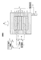
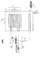
- FIG. 1 is a schematic configuration view showing a configuration example of a chemical reaction device according to a first embodiment.
- the laminated body 10 and the electrolytic cell 21 have shown the cross-sectional structure.
- the chemical reaction device includes a laminate 10, an electrolytic cell 21, an external power supply 32, a power demand unit 34, a switching element control unit 41, and an electrolyte solution control unit 61. .
- the electrolytic cell 21 accommodates the laminate 10 therein. Moreover, the electrolytic cell 21 accommodates the electrolyte solution 23 in the inside so that the laminated body 10 may be immersed.
- the electrolytic solution 23 is, for example, a solution containing H 2 O. As such a solution, one containing an optional electrolyte can be mentioned, but it is desirable that it accelerates the oxidation reaction of H 2 O.
- the electrolytic solution 23 is, for example, a solution containing CO 2 .
- the upper surface of the electrolytic cell 21 is provided with a window made of, for example, glass or acrylic having high light transmittance. The irradiation light is irradiated from above the electrolytic cell 21.
- the laminated body 10 performs an oxidation-reduction reaction by the irradiation light.
- a pipe 22 is connected to the electrolytic cell 21.
- the pipe 22 injects the electrolytic solution 23 into the electrolytic cell 21, or discharges the electrolytic solution 23 from the electrolytic cell 21.
- the electrolytic solution control unit 61 controls the electrolytic solution 23 in the electrolytic cell 21. More specifically, the electrolytic solution control unit 61 measures the amount of the electrolytic solution 23 in the electrolytic cell 21, and controls the injection and discharge of the electrolytic solution 23 by the pipe 22. Thereby, the electrolytic solution control unit 61 fills the inside of the electrolytic cell 21 with the electrolytic solution 23 so that a sufficient electrolytic reaction occurs when it is used as an artificial photosynthesis system and an electrolysis system. In addition, when used as a solar cell, the electrolytic solution control unit 61 discharges the electrolytic solution 23 from the inside of the electrolytic cell 21 so that the electricity does not flow in the electrolytic solution 23, and the electrolytic cell 21 is filled with air. In addition to air, any substance having low conductivity may be gas or liquid.
- the stacked body 10 includes a first electrode 16, a photovoltaic layer 15, a second electrode 11, a first catalyst 17, and a second catalyst 18.
- the laminated body 10 is a flat plate shape which spreads in a plane, and is sequentially formed by using the second electrode 11 as a base material (substrate).
- the light irradiation side is referred to as the front surface (upper surface), and the opposite side to the light irradiation side is referred to as the back surface (lower surface).
- the second electrode 11 has conductivity.
- the second electrode 11 is provided to support the stacked body 41 and to increase its mechanical strength.
- the second electrode 11 is made of, for example, a metal plate such as Cu, Al, Ti, Ni, Fe, or Ag, or an alloy plate such as SUS including at least one of them.
- the second electrode 11 may be made of conductive resin or the like.
- the second electrode 11 may be formed of a semiconductor substrate such as Si or Ge, or an ion exchange membrane.
- the photovoltaic layer 15 is formed on the second electrode 11 (on the surface (on the upper surface)).
- the photovoltaic layer 15 is composed of a first photovoltaic layer 12, a second photovoltaic layer 13, and a third photovoltaic layer 14.
- Each of the first photovoltaic layer 12, the second photovoltaic layer 13, and the third photovoltaic layer 14 is a solar cell using a pin junction semiconductor, and the absorption wavelengths of light are different. By laminating these layers in a planar manner, the photovoltaic layer 15 can absorb light of a wide wavelength of sunlight, and it becomes possible to use sunlight energy more efficiently. Moreover, since each photovoltaic layer is connected in series, a high open circuit voltage can be obtained.
- the first photovoltaic layer 12 is formed on the second electrode 11, and for example, an n-type amorphous silicon (a-Si) layer formed in order from the lower side, an intrinsic amorphous silicon. It is composed of a silicon germanium (a-SiGe) layer and a p-type microcrystalline silicon ( ⁇ c-Si) layer.
- a-SiGe layer is a layer that absorbs light in a long wavelength region of about 700 nm. That is, charge separation occurs in the first photovoltaic layer 12 by the light energy in the long wavelength region.
- the second photovoltaic layer 13 is formed on the first photovoltaic layer 12 and, for example, an n-type a-Si layer, an intrinsic a-SiGe layer, and an in-situ a-SiGe layer, which are sequentially formed from the lower side. It is composed of a p-type ⁇ c-Si layer.
- the a-SiGe layer is a layer that absorbs light in an intermediate wavelength region of about 600 nm. That is, charge separation occurs in the second photovoltaic layer 13 by the light energy in the intermediate wavelength region.
- the third photovoltaic layer 14 is formed on the second photovoltaic layer 13 and, for example, an n-type a-Si layer, an intrinsic a-Si layer, and an intrinsic a-Si layer sequentially formed from the lower side, and It is composed of a p-type ⁇ c-Si layer.
- the a-Si layer is a layer that absorbs light in a short wavelength region of about 400 nm. That is, charge separation occurs in the third photovoltaic layer 14 by the light energy in the short wavelength region.
- the photovoltaic layer 15 charge separation occurs by light in each wavelength region. That is, holes are separated on the anode side (front side) and electrons are separated on the cathode side (back side). Thereby, the photovoltaic layer 15 generates an electromotive force.
- the first electrode 16 is formed on the p-type semiconductor layer (p-type ⁇ c-Si layer) of the photovoltaic layer 15. Therefore, it is desirable that the first electrode 16 be made of a material that can make ohmic contact with the p-type semiconductor layer.
- the first electrode is made of, for example, a metal such as Ag, Au, Al, or Cu, or an alloy containing at least one of them.
- the first electrode 16 may be made of a transparent conductive oxide such as ITO, ZnO, FTO, AZO, or ATO.
- the first electrode 16 may have, for example, a structure in which a metal and a transparent conductive oxide are laminated, a structure in which a metal and another conductive material are composited, or a transparent conductive oxide and another conductive material are composited. It may be configured in the following structure.
- the irradiation light passes through the first electrode 16 and reaches the photovoltaic layer 15. Therefore, the first electrode 16 disposed on the light irradiation side (upper side in the drawing) has light transparency to the irradiation light. More specifically, the light transmittance of the first electrode 16 on the light irradiation side is preferably at least 10% or more, more preferably 30% or more of the irradiation amount of the irradiation light. Alternatively, the first electrode 16 has an opening portion capable of transmitting light. That is, the shape of the first electrode 16 is not limited to a thin film, and may be a lattice, a particle, or a wire. The aperture ratio is at least 10% or more, more preferably 30% or more.
- the photovoltaic layer 15 configured by the laminated structure of the three photovoltaic layers (the first photovoltaic layer 12, the second photovoltaic layer 13, and the third photovoltaic layer 14) is obtained.
- the photovoltaic layer 15 may be composed of a laminated structure of two or four or more photovoltaic layers.
- one photovoltaic layer may be used instead of the laminated structure of photovoltaic layers.
- the solar cell using a pin junction semiconductor was demonstrated above, the solar cell using a pn junction type semiconductor may be sufficient.
- the semiconductor layer is made of Si and Ge
- the semiconductor layer is not limited thereto, and may be made of a compound semiconductor such as GaAs, GaInP, AlGaInP, CdTe, or CuInGaSe.
- various forms of single crystal, polycrystal and amorphous can be applied.
- the first electrode 16 and the second electrode 11 may be provided on the entire surface of the photovoltaic layer 15, or may be provided partially.
- the first catalyst 17 is formed on the upper surface of the first electrode 16.
- the first catalyst 17 is provided to enhance the chemical reactivity (oxidation reactivity) near the surface of the first electrode 16.
- an aqueous solution ie, a solution containing H 2 O
- the first electrode 16 oxidizes H 2 O to generate O 2 and H + .
- the first catalyst 17 is made of a material that reduces the activation energy for oxidizing H 2 O. In other words, it is made of a material that reduces the overvoltage in oxidizing H 2 O to generate O 2 and H + .
- the shape of the first catalyst 17 is not limited to a thin film, and may be a lattice, a particle, or a wire.
- the catalyst performance may be provided to the metal portion in the structure in which the metal and the transparent conductive oxide in the first electrode 16 are stacked, or in the structure in which the metal and the other conductive material are combined.
- the electrode metal itself may have catalytic performance. This can simplify the structure.
- the second catalyst 18 is formed on the lower surface of the second electrode 11.
- the second catalyst 18 is provided to enhance the chemical reactivity (reduction reactivity) in the vicinity of the back surface of the second electrode 11.
- the CO 2 is reduced to form carbon compounds (eg, CO, HCOOH, CH 4 , CH 3 OH, C 2 H 5 OH, C 2 H 4 ) and the like Do.
- the second catalyst 18 is made of a material that reduces the activation energy for reducing CO 2 . In other words, it is made of a material that reduces the overpotential in reducing CO 2 to form a carbon compound.
- Such materials include Au, Ag, Cu, Pt, C, Ni, Zn, C, graphene, carbon nanotubes (CNTs), fullerenes, ketjen black or metals such as Pd, or at least one of them. Alloys or metal complexes such as Ru complexes or Re complexes may be mentioned.
- an aqueous solution containing no CO 2 ie, H 2 O containing no CO 2
- H 2 O is reduced to generate H 2 .
- the second catalyst 18 is made of a material that reduces the activation energy for reducing H 2 O. In other words, it is made of a material that reduces the overvoltage in reducing H 2 O to generate H 2 .
- a metal such as Ni, Fe, Pt, Ti, Au, Ag, Zn, Pd, Ga, Mn, Cd, C, graphene, or an alloy containing at least one of them can be mentioned.
- the shape of the second catalyst 18 is not limited to a thin film, and may be a lattice, a particle, or a wire.
- the layered structure of the photovoltaic layer 15 may be reversed, and the action of reducing the overvoltage of the first electrode 16 and the second electrode 11 by the first catalyst 17 and the second catalyst 18 may be reversed.
- the external power supply 32 is electrically connected between the first electrode 16 and the second electrode 11 via the first switching element 31.
- the first switching element 31 is formed between the external power supply 32 and the first electrode 16 or the second electrode 11.
- the first switching element 31 is turned on, the first electrode 16 and the second electrode 11 are electrically connected to each other through the external power supply 32.
- the first switching element 31 is turned off, the first electrode 16 and the second electrode 11 are electrically disconnected via the external power supply 32.
- the first electrode 16 is connected to the anode side of the external power supply 32, and the second electrode 11 is connected to the cathode side.
- the external power supply 32 supplies power to the first electrode 16 and the second electrode 11 when there is surplus power.
- the power demand unit 34 is electrically connected between the first electrode 16 and the second electrode 11 via the second switching element 33. Further, the power demand unit 34 is connected in parallel with the external power supply 32. In other words, the second switching element 33 is formed between the power demand portion 34 and the first electrode 16 or the second electrode 11. Then, by turning on the second switching element 33, the first electrode 16 and the second electrode 11 are electrically connected via the power demand unit 34. On the other hand, when the first switching element 31 is turned off, the first electrode 16 and the second electrode 11 are electrically disconnected via the power demand unit 34. Although details will be described later, power is supplied from the photovoltaic layer 15 to the power demand unit 34 when there is no surplus power.
- the power demand unit 34 is, for example, a storage battery that stores power or a region that consumes power.
- the switching element control unit 41 controls the on / off of the first switching element 31 and the second switching element 33 according to conditions such as the presence or absence of surplus power exceeding the demand of the power demand unit 34 and the presence or absence of solar energy. .
- the switching element control unit 41 turns off the first switching element 31 and the second switching element 33 when there is surplus power and there is solar energy.
- the first electrode 16 and the second electrode 11 are electrically connected only through the photovoltaic layer 15.
- electrolysis is performed in the first electrode 16 and the second electrode 11 by the electromotive force of the photovoltaic layer 15 to generate chemical energy. That is, the chemical reaction device functions as an artificial photosynthesis system.
- the switching element control unit 41 turns off the second switching element 33 and turns on the first switching element 31.
- the first electrode 16 and the second electrode 11 are electrically connected via the external power supply 32.
- electrolysis is performed at the first electrode 16 and the second electrode 11 by the electromotive force from the external power supply 32 to generate chemical energy. That is, the chemical reaction device functions as an electrolysis system.
- the switching element control unit 41 turns off the first switching element 31 and turns on the second switching element 33.
- the photovoltaic layer 15 and the power demand part 34 are electrically connected.
- power is supplied to the power demand unit 34 by the electromotive force of the photovoltaic layer 15. That is, the chemical reaction device functions as a solar cell.
- the artificial photosynthesis system can operate the hybrid by compensating the current through the externally adjusted electric device.
- the artificial photosynthesis system may change the product by adjusting the voltage and current through an externally adjusted electrical device according to the demand for the product.
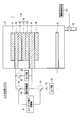
- FIG. 2 is a diagram showing the artificial photosynthesis system operation of the chemical reaction device according to the first embodiment.
- the artificial light synthesis system is mainly used when there is surplus power and there is solar energy.
- the switching element control unit 41 turns off the first switching element 31 and the second switching element 33. Thereby, the first electrode 16 and the second electrode 11 are electrically disconnected via the external power supply 32. In addition, the first electrode 16 and the second electrode 11 are electrically disconnected via the power demand unit 34.
- the electrolytic solution control unit 61 controls the amount of the electrolytic solution 23 in the electrolytic cell 21 so that the first electrode 16 and the second electrode 11 are immersed in the electrolytic solution 23.
- the electrolytic solution 23 is injected into the electrolytic cell 21 through the pipe 22, and the electrolytic cell 21 is filled with the electrolytic solution 23.
- the inside of the electrolytic cell 21 may not be filled with the electrolytic solution 23, and at least a part of the first electrode 16 and the second electrode 11 may be immersed in the electrolytic solution 23.
- the photovoltaic layer 15 When light is irradiated from above in this state, the irradiation light passes through the first electrode 16 and reaches the photovoltaic layer 15.
- the photovoltaic layer 15 absorbs light, it generates electrons and holes paired therewith and separates them. That is, in each of the photovoltaic layers (the first photovoltaic layer 12, the second photovoltaic layer 13, and the third photovoltaic layer 14), electrons are formed on the n-type semiconductor layer side (the second electrode 11 side) Moves, and the holes generated as electron pairs move to the p-type semiconductor layer side (the first electrode 16 side) to cause charge separation. Thereby, an electromotive force is generated in the photovoltaic layer 15.
- the electrons generated in the photovoltaic layer 15 and transferred to the second electrode 11 that is the electrode on the cathode side are used for the reduction reaction in the vicinity of the back surface of the second electrode 11 (near the second catalyst 18).
- holes generated in the photovoltaic layer 15 and transferred to the first electrode 16 as the anode side electrode are used for oxidation reaction near the surface of the first electrode 16 (near the first catalyst 17) .
- a reaction of formula (1) occurs near the surface of the first electrode 16 in contact with the electrolytic solution 23, and a reaction of formula (2) occurs near the back surface of the second electrode 11.
- the photovoltaic layer 15 needs to have an open circuit voltage equal to or greater than the potential difference between the standard redox potential of the oxidation reaction generated at the first electrode 16 and the standard redox potential of the reduction reaction generated at the second electrode 11.
- the standard redox potential of the oxidation reaction in the formula (1) is 1.23 [V]
- the standard redox potential of the reduction reaction in the formula (2) is -0.1 [V].
- the open circuit voltage of the photovoltaic layer 15 needs to be 1.33 [V] or more. More preferably, the open circuit voltage needs to be equal to or higher than the potential difference including the overvoltage. More specifically, for example, when the overvoltage of the oxidation reaction in the formula (1) and the reduction reaction in the formula (2) are each 0.2 [V], the open circuit voltage is 1.73 [V] or more desirable.
- the solar energy generates an electromotive force in the photovoltaic layer 15, and the electromotive force causes an oxidation-reduction reaction (electrolytic reaction) to generate chemical energy. That is, solar energy can be converted to chemical energy.
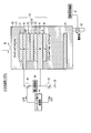
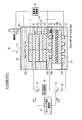
- FIG. 3 is a view showing the electrolytic system operation of the chemical reaction device according to the first embodiment.
- the electrolysis system is mainly used when there is surplus power and there is no solar energy.
- the electrolysis system may be used at night.
- the switching element control unit 41 turns on the first switching element 31. Thereby, the first electrode 16 and the second electrode 11 are electrically connected via the external power supply 32. On the other hand, the switching element control unit 41 turns off the second switching element 33. Thus, the first electrode 16 and the second electrode 11 are electrically disconnected via the power demand unit 34.
- the electrolytic solution control unit 61 controls the amount of the electrolytic solution 23 in the electrolytic cell 21 so that the first electrode 16 and the second electrode 11 are immersed in the electrolytic solution 23.
- the electrolytic solution 23 is injected into the electrolytic cell 21 through the pipe 22, and the electrolytic cell 21 is filled with the electrolytic solution 23.
- the inside of the electrolytic cell 21 may not be filled with the electrolytic solution 23, and at least a part of the first electrode 16 and the second electrode 11 may be immersed in the electrolytic solution 23.
- H 2 O is oxidized (los electrons) to generate O 2 and hydrogen ions (H + ). Then, H + generated at the first electrode 16 side moves to the second electrode 11 side.
- the photovoltaic layer 15 needs to have an open circuit voltage equal to or greater than the potential difference between the standard redox potential of the oxidation reaction generated at the first electrode 16 and the standard redox potential of the reduction reaction generated at the second electrode 11.
- the standard redox potential of the oxidation reaction in the formula (1) is 1.23 [V]
- the standard redox potential of the reduction reaction in the formula (2) is -0.1 [V].
- the open circuit voltage of the photovoltaic layer 15 needs to be 1.33 [V] or more. More preferably, the open circuit voltage needs to be equal to or higher than the potential difference including the overvoltage. More specifically, for example, when the overvoltage of the oxidation reaction in the formula (1) and the reduction reaction in the formula (2) are each 0.2 [V], the open circuit voltage is 1.73 [V] or more desirable.
- the amount of current flowing may be small depending on the direction of the configuration of the semiconductor layer.
- an electromotive force is generated in the external power supply 32 by the electrical energy of the surplus power, and the electromotive force causes an oxidation-reduction reaction (electrolytic reaction) to generate chemical energy. That is, electrical energy can be converted to chemical energy.
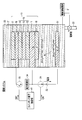
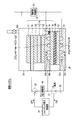
- FIG. 4 is a view showing the solar cell operation of the chemical reaction device according to the first embodiment.
- FIG. 5 is a view showing a modified example of the solar cell operation of the chemical reaction device according to the first embodiment. Solar cells are mainly used when there is no surplus power.
- the switching element control unit 41 when used as a solar cell, the switching element control unit 41 turns off the first switching element 31. Thereby, the first electrode 16 and the second electrode 11 are electrically disconnected via the external power supply 32. On the other hand, the switching element control unit 41 turns on the second switching element 33. Thus, the first electrode 16 and the second electrode 11 are electrically connected via the power demand unit 34.
- the electrolytic solution control unit 61 controls the amount of the electrolytic solution 23 in the electrolytic cell 21 so that the first electrode 16 and the second electrode 11 are not immersed in the electrolytic solution 23. Thereby, the electrolytic solution 23 is discharged from the inside of the electrolytic cell 21 through the pipe 22, and the inside of the electrolytic cell 21 is filled with air.
- the inside of the electrolytic cell 21 may not be filled with air, and at least a part of the first electrode 16 or a part of the second electrode 11 may not be immersed in the electrolytic solution 23.
- a part of the inside of the electrolytic cell 21 may be filled with a gas (for example, O 2 or the like) generated by the above-described artificial photosynthesis system or the electrolysis system.
- a gas for example, O 2 or the like
- the oxidation electrode (first electrode 16) and the reduction electrode (second electrode 11) may be separated by a partition wall where ion migration is not performed.
- the electrolytic solution 23 discharged to the electrolytic solution storage tank connected to the pipe 22 may be stored via the pipe 22.
- the inside of the electrolytic cell 21 may be filled with a non-conductive liquid instead of a gas.
- the photovoltaic layer 15 When light is irradiated from above in this state, the irradiation light passes through the first electrode 16 and reaches the photovoltaic layer 15.
- the photovoltaic layer 15 absorbs light, it generates electrons and holes paired therewith and separates them. That is, in each of the photovoltaic layers (the first photovoltaic layer 12, the second photovoltaic layer 13, and the third photovoltaic layer 14), electrons are formed on the n-type semiconductor layer side (the second electrode 11 side) Moves, and the holes generated as electron pairs move to the p-type semiconductor layer side (the first electrode 16 side) to cause charge separation. Thereby, an electromotive force is generated in the photovoltaic layer 15. Power can be supplied to the power demand unit 34 by the electromotive force generated by the photovoltaic layer 15.
- the solar energy generates an electromotive force in the photovoltaic layer 15, and the electromotive force generates electrical energy. That is, solar energy can be converted to electrical energy.
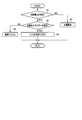
- FIG. 6 is a flowchart showing the operation of the chemical reaction device according to the first embodiment.
- step S1 the chemical reaction device checks whether there is surplus power exceeding the demand of the power demand unit 34.
- step S1 If there is no surplus power in step S1, the chemical reaction device functions as a solar cell in step S2. More specifically, when there is no surplus power, the switching element control unit 41 turns off the first switching element 31 and turns on the second switching element 32. Thereby, the photovoltaic layer 15 and the power demand unit 34 are electrically connected, and power is supplied to the power demand unit 34 by the electromotive force of the photovoltaic layer 15.
- step S1 If there is surplus power in step S1, the chemical reaction device checks in step S3 whether there is solar energy or not.
- the chemical reaction device functions as an electrolysis system in step S4. More specifically, when there is no sunlight energy, the switching element control unit 41 turns off the second switching element 33 and turns on the first switching element 31. Thereby, the first electrode 16 and the second electrode 11 are electrically connected via the external power supply 32, and electrolysis is performed in the first electrode 16 and the second electrode 11 by the electromotive force by the external power supply 32, and chemical energy is generated. Is generated.
- step S3 If there is sunlight energy in step S3, the chemical reaction device functions as an artificial photosynthesis system in step S5. More specifically, when there is sunlight energy, the switching element control unit 41 turns off the first switching element 31 and the second switching element 33. Thereby, the first electrode 16 and the second electrode 11 are electrically connected only through the photovoltaic layer 15, and the electromotive force of the photovoltaic layer 15 causes electrolysis in the first electrode 16 and the second electrode 11. The chemical energy is generated to take place.
- the chemical reaction device appropriately operates as an artificial photosynthesis system, a solar cell, and an electrolysis system according to various conditions.
- the operation of the chemical reaction device is not limited to the above.
- the electrolytic operation can be performed without the surplus power, and the chemical substance may be produced instead of the power.
- various reactions may be performed with an appropriate balance depending on the state of charge such as an external battery or stored water of pumped storage power generation.
- the chemical reaction device accommodates the stacked body 10 including the first electrode 16, the photovoltaic layer 15, and the second electrode 11, and the stacked body 10. And an external power source 32 and a power demand unit 34 that can be electrically connected to or disconnected from the laminate 10. That is, the connection between the stacked body 10 and the external power supply 32 and the connection between the stacked body 10 and the power demand unit 34 can be switched. Moreover, it is also possible not to electrically connect (cut off) the stacked body 10 to any of the external power supply 32 and the power demand unit 34.
- the chemical reaction device can function as an electrolysis system. Further, by electrically connecting the stacked body 10 and the power demand unit 34, the chemical reaction device can function as a solar cell. Furthermore, by electrically interrupting the laminate 10, the external power supply 32, and the power demand unit 34, the chemical reaction device can function as an artificial photosynthesis system. These connections are determined by the presence or absence of surplus power and the presence or absence of solar energy.
- the energy conversion efficiency is increased according to various conditions such as the presence or absence of surplus power and the presence or absence of sunlight energy.
- An integrated chemical reactor can be provided that operates.
- FIG. 7 is a schematic configuration view showing a configuration of a first modification of the chemical reaction device according to the first embodiment.
- the second electrode 11 physically separates the electrolytic cell 21 into the first electrolytic cell 25 and the second electrolytic cell 26. To separate.
- the first electrolytic cell 25 accommodates the first electrolytic solution 23 a therein so as to immerse the surface (the first catalyst 17) of the first electrode 16.
- the first electrolytic solution 23 a is, for example, a solution containing H 2 O.
- a solution one containing an optional electrolyte can be mentioned, but it is desirable that it accelerates the oxidation reaction of H 2 O.
- the upper surface of the first electrolytic cell 25 is provided with a window made of, for example, glass or acrylic having high light transmittance. The irradiation light is irradiated from above the first electrolytic cell 25.
- a pipe 22 a is connected to the first electrolytic cell 25.
- the pipe 22 a injects the first electrolytic solution 23 a into the first electrolytic cell 25 or discharges the first electrolytic solution 23 a from the inside of the first electrolytic cell 25.
- the second electrolytic cell 26 accommodates the second electrolytic solution 23 b therein so as to immerse the back surface (the second catalyst 18) of the second electrode 11.
- the second electrolytic solution 23 b is, for example, a solution containing CO 2 .
- the second electrolyte solution 23 b desirably has a high CO 2 absorption rate, and examples of the solution containing H 2 O include aqueous solutions of NaHCO 3 and KHCO 3 .
- the first electrolyte 23a and the second electrolyte 23b may be the same solution, but the second electrolyte 23b preferably has a high CO 2 absorption amount, so the first electrolyte 23a, the second electrolyte 23b, and the second electrolyte 23b may be used.
- the second electrolyte solution 23b reduces the reduction potential of the CO 2, high ion conductivity, it is desirable to have CO 2 absorbent that absorbs CO 2.
- an electrolytic solution an ionic liquid or an aqueous solution comprising a salt of a cation such as imidazolium ion or pyridinium ion and an anion such as BF 4- or PF 6- and in a liquid state in a wide temperature range can be used. It can be mentioned.
- an amine solution such as ethanolamine, imidazole or pyridine or an aqueous solution thereof can be mentioned.
- the amine may be either a primary amine, a secondary amine or a tertiary amine.
- primary amines include methylamine, ethylamine, propylamine, butylamine, pentylamine, hexylamine and the like.
- the hydrocarbon of amine may be substituted by alcohol, halogen or the like. Examples of those in which the amine hydrocarbon is substituted include methanolamine, ethanolamine, and chloromethylamine. In addition, unsaturated bonds may be present. These hydrocarbons are also similar to secondary amines and tertiary amines.
- secondary amines include dimethylamine, diethylamine, dipropylamine, dibutylamine, dipentylamine, dihexylamine, dimethanolamine, diethanolamine, and dipropanolamine.
- the substituted hydrocarbons may be different. This is also true for tertiary amines.
- different hydrocarbons include methyl ethylamine, methyl propyl amine and the like.
- trimethylamine, triethylamine, tripropylamine, tributylamine, trihexylamine, trimethanolamine, triethanolamine, triethanolamine, tripropanolamine, tributanolamine, tripropanolamine, triexanolamine, methyl diethylamine, or Methyl dipropyl amine etc. are mentioned.
- 2-position of the imidazolium ion may be substituted.
- imidazolium ion substituted at the 2-position examples include 1-ethyl-2,3-dimethylimidazolium ion, 1,2-dimethyl-3-propylimidazolium ion, 1-butyl 2,3-dimethyl ion Examples thereof include imidazolium ion, 1,2-dimethyl-3-pentylimidazolium ion, and 1-hexyl-2,3-dimethylimidazolium ion.
- pyridinium ions include methyl pyridinium, ethyl pyridinium, propyl pyridinium, butyl pyridinium, pentyl pyridinium, and hexyl pyridinium. Both the imidazolium ion and the pyridinium ion may be substituted with an alkyl group, or an unsaturated bond may be present.
- anion fluoride ion, chloride ion, bromide ion, iodide ion, BF 4 ⁇ , PF 6 ⁇ , CF 3 COO ⁇ , CF 3 SO 3 ⁇ , NO 3 ⁇ , SCN ⁇ , (CF 3 SO 2 3 C ⁇ , bis (trifluoromethoxysulfonyl) imide, bis (trifluoromethoxysulfonyl) imide, or bis (perfluoroethylsulfonyl) imide and the like.
- it may be a zwitterion in which the cation and the anion of the ionic liquid are linked by a hydrocarbon.
- a pipe 22 b is connected to the second electrolytic cell 26.
- the pipe 22 b injects the second electrolytic solution 23 b into the second electrolytic cell 26 or discharges the second electrolytic solution 23 b from the inside of the second electrolytic cell 26.
- the electrolytic solution control unit 61 controls the first electrolytic solution 23 a in the first electrolytic cell 25 and the second electrolytic solution 23 b in the second electrolytic cell 26. More specifically, the electrolytic solution control unit 61 measures the amounts of the first electrolytic solution 23 a in the first electrolytic cell 25 and the second electrolytic solution 23 b in the second electrolytic cell 26, and The injection and discharge of the second electrolytic solution 23 b by the solution 23 a and the pipe 22 b are controlled.
- the electrolytic solution control unit 61 fills the inside of the first electrolytic cell 25 with the first electrolytic solution 23 a so that a sufficient electrolytic reaction occurs when it is used as an artificial photosynthesis system and an electrolytic system, and the second electrolytic cell 26 The inside is filled with the second electrolytic solution 23 b.
- the first electrolyte 23a or the first electrolyte 23a may be removed from the first electrolytic cell 25 so that electricity does not flow in the first electrolyte 23a or the second electrolyte 23b.
- the second electrolytic solution 23b is discharged from the inside of the electrolytic cell 26, and the inside of the first electrolytic cell 25 or the second electrolytic cell 26 is filled with air.
- the second electrode 11 physically separates the electrolytic cell 21 into a first electrolytic cell 25 and a second electrolytic cell 26.
- the back surface of the second electrode 11 is disposed on the side of the second electrolytic cell 26, and is accommodated in the second electrolytic cell 26.
- the surface of the second electrode 11 is disposed on the side of the first electrolytic cell 25, but an insulating layer (not shown) is formed on the surface of the second electrode 11 to form the second electrode 11 and the first electrolyte 23 a.
- the reaction may be suppressed by replacing the first electrolytic solution 23a with a nonconductive liquid or gas.
- the reaction potential of the catalyst may be set to a potential at which the reaction does not occur between the second electrode 11 and the first electrolytic solution 23a.
- the above can be realized by adjusting the reaction potential of the catalyst.
- the second electrode 11 has an ion migration path at its exposed portion.
- the ion migration path is, for example, a plurality of pores penetrating from the front surface to the back surface.
- the pores selectively allow only ions (for example, H ions (H + )) generated by the oxidation reaction of the first electrode 16 in the first electrolytic cell 25 to pass through the second electrolytic cell 26.
- the ions that have passed through the pores are converted to O 2 , H 2 , or an organic compound by a reduction reaction at the second electrode 11 of the second electrolytic cell 26.
- the pore may have a size through which ions pass.
- the lower limit of the diameter (equivalent circle diameter) of the pores is preferably 0.3 nm or more.
- the area ratio S1 / S2 of the total area S1 of the plurality of pores and the area S2 of the ion permeable member 21a is 0.9 or less, preferably 0.6 or less so as not to impair the mechanical strength.
- the shape of the pores is not limited to a circular shape, and may be an elliptical shape, a triangular shape, or a rectangular shape.
- the arrangement configuration of the pores is not limited to the square lattice shape, and may be a triangular lattice shape or random.
- the pores may be filled with the ion exchange membrane 19.
- Ion exchange membranes include, for example, cation exchange membranes, such as Nafion or Flemion, anion exchange membranes, such as Neosepter or cermion.
- the pores may be filled with a glass filter or agar.
- the second electrode 11 may have a plurality of slits penetrating from the front surface to the back surface and filled with the ion exchange membrane 19 instead of the pores.
- the slits allow only ions (for example, H ions (H + )) generated by the oxidation reaction of the first electrode 16 in the first electrolytic cell 25 to selectively pass through the second electrolytic cell 26.
- the transfer of ions may be promoted by providing a pump in the ion transfer path.
- the electrolytic solution is filled in each of the electrolytic cells (the first electrolytic cell 25 and the second electrolytic cell 26), and the electrolytic cell is not filled (filled with air) ) State can be configured.
- the electrolytic cell 21 by separating the electrolytic cell 21 into the first electrolytic cell 25 and the second electrolytic cell 26, different electrolytic solutions (the first electrolytic solution 23a and the second electrolytic solution) which are easily reacted in each electrolytic cell 23b) can be filled. Further, by separating the electrolytic cell 21 into a first electrolytic cell 25 and a second electrolytic cell 26, an oxidation reaction is performed on the first electrolytic cell 25 side, and a reduction reaction is performed on the second electrolytic cell 26 side. As a result, the product (for example, O 2 ) by the oxidation reaction can be recovered by the first electrolytic cell 25, and the product (for example, CO) by the reduction reaction can be recovered by the second electrolytic cell 26. That is, the product of the oxidation reaction and the product of the reduction reaction can be separated and recovered.
- the electrolytic solutions in the first electrolytic cell 25 and the second electrolytic cell 26 can be changed to cause different reactions when used as an electrolysis system and when used as an artificial photosynthesis system. As a result, it is possible to cause an optimal reaction with respect to the reaction current density which varies depending on the light intensity, the surplus power amount and the like.
- FIG. 8 is a schematic configuration view showing a configuration of a second modified example of the chemical reaction device according to the first embodiment.
- the sensor portions 42 and 43 are electrically connected between the first electrode 16 and the second electrode 11. Ru.
- the sensor unit 42 is electrically connected between the first electrode 16 and the second electrode 11 via the switching element 31 and the external power supply 32.
- the first switching element 31 is formed between the sensor unit 42 and the first electrode 16 or the second electrode 11. Then, by turning on the first switching element 31, the first electrode 16 and the second electrode 11 are electrically connected via the external power supply 32 and the sensor unit 42. On the other hand, when the first switching element 31 is turned off, the first electrode 16 and the second electrode 11 are electrically disconnected via the external power supply 32 and the sensor unit 42. That is, when the chemical reaction device is mainly used as an electrolysis system, the sensor unit 42 functions.
- the sensor unit 43 is electrically connected between the first electrode 16 and the second electrode 11 via the third switching element 35.
- the third switching element 35 is formed between the sensor unit 43 and the first electrode 16 or the second electrode 11. Then, by turning on the third switching element 35, the first electrode 16 and the second electrode 11 are electrically connected to each other through the sensor unit 43. On the other hand, when the third switching element 35 is turned off, the first electrode 16 and the second electrode 11 are electrically disconnected via the sensor unit 43. That is, when the chemical reaction device is mainly used as an artificial photosynthesis system, the sensor unit 43 functions.
- the sensor unit 42 uses, for example, the electromotive force of the external power supply 32 in the case of an electrolysis system, and captures an electrical signal obtained by the reaction between the electrolyte solution 23 and the first electrode 16 and the second electrode 11.
- the sensor unit 42 has the pH of the electrolyte solution 23, the concentration of the electrolyte solution 23, the composition of the electrolyte solution 23, the pressure in the electrolysis tank 21, the temperature in the electrolysis tank 21, and the light intensity. Measure etc.
- the sensor unit 43 uses an electromotive force of the photovoltaic layer 15 to capture an electrical signal obtained by the reaction of the electrolytic solution 23 with the first electrode 16 and the second electrode 11.
- the sensor unit 43 has the pH of the electrolytic solution 23, the concentration of the electrolytic solution 23, the composition of the electrolytic solution 23, the pressure in the electrolytic cell 21, the temperature in the electrolytic cell 21, and Measure the strength etc.
- the sensor unit 43 utilizes the electromotive force of the photovoltaic layer 15, and thus can operate without a power supply.
- the sensor part 43 may use the inter-liquid potential.
- the sensor unit 43 can obtain information such as the pH and the concentration of the electrolytic solution from the inter-liquid potential. Further, the sensor unit 43 can use the inter-liquid potential as a power supply.
- the sensor unit 42 may be temporarily operated by the external power supply 32 to measure various requirements.
- the sensor parts 42 and 43 are suitable for the one that generates light by reaction, the one that causes a reaction by light, and the one that changes the reaction by light.
- the light is not limited to visible light, but may be electromagnetic waves or radiation acting on the photovoltaic layer 15.
- the sensor units 42 and 43 detect the electric signal, and the state (pH, concentration, and composition) of the electrolytic solution 23 according to the light and radiation generated by the change or absorption of light due to the reaction or the progress of the reaction It is also possible to detect the condition.
- the sensor portions 42 and 43 detect the pH of the electrolytic solution 23, the concentration of the electrolytic solution 23, the composition of the electrolytic solution 23, the pressure in the electrolytic cell 21, the temperature in the electrolytic cell 21, and the light intensity. Measure etc. Thereby, the condition of the electrolytic solution 23 and the electrolytic cell 21 for promoting the electrolytic reaction can be appropriately adjusted.
- Light energy may be stored as a reductant of matter by the electromotive force of the photovoltaic layer 15 in the artificial photosynthesis system.
- light energy may reduce a substance and store the reduced substance as reduction energy.
- the reductant indicates one having a reducing power.
- a reductant is one that is oxidized by itself to lose an electron and gives the electron to another substance to reduce the other substance.
- 1-valent ions of iodine by light energy (I -) 3 Conversion to a valence ion (I 3 ⁇ ) may, for example, be mentioned.
- H + may be stored as a reductant.
- the reductant obtained by the artificial photosynthesis system may be further reduced by the electromotive force of the external power supply 32 in the electrolysis system. Thereby, it can be converted to a reductant with higher energy density.
- electrical energy may be obtained from reduction energy by performing a reaction of oxidizing the reductant obtained by the artificial photosynthesis system and returning it to the original state. That is, it becomes an artificial-light-synthesis system which has an electrical storage function.
- a compound such as lithium can be used as the electrolyte, and a storage function can be provided by interaction with the electrodes.
- a fuel cell More specifically, light energy decomposes water to produce hydrogen and oxygen. The obtained oxygen and hydrogen share at least one electrode to generate water with hydrogen and oxygen. Thereby, power can be obtained. That is, the fuel cell can be integrated into the artificial light synthesis system. The reaction efficiency can be improved by providing a flow passage in the electrolytic cell 21 as in a normal fuel cell.
- a solid polymer membrane used in a polymer electrolyte fuel cell may be formed between the first electrode 16 and the second electrode 11.
- the heat accompanying the power generation at this time, or the heat of the electrolyte warmed by sunlight may be used as the utilization medium.
- the heat utilization medium is not limited to the electrolyte, and another heat medium may be provided on the second electrode 11 or on a copper pipe (not shown) in the electrolytic solution 23.
- the chemical reaction device not only the laminate 10 including the first electrode 16, the photovoltaic layer 15, and the second electrode 11 but also the second electrode 11 are separated in the electrolytic cell 21.
- the opposing third electrode 51 is disposed.
- an external power supply 32 can be electrically connected between the second electrode 11 and the third electrode 51, and the second electrode 11, the third electrode 51, and the external power supply 32 can function as an electrolysis system.
- FIG. 9 is a schematic configuration view showing a configuration example of a chemical reaction device according to a second embodiment.
- the laminated body 10, the 3rd electrode 51, and the electrolytic cell 21 have shown the cross-sectional structure.
- the chemical reaction device according to the second embodiment differs from the first embodiment in that not only the first electrode 16 and the second electrode 11 but also the third electrode 51 is provided. It is.
- the third electrode 51 is accommodated in the electrolytic cell 21 and is disposed on the side opposite to the light irradiation side of the second electrode 11 so as to be separated from and opposite to the light irradiation side.
- the third electrode 51 is formed of, for example, a metal plate such as Cu, Al, Ti, Ni, Fe, or Ag, or an alloy plate such as SUS including at least one of them.
- the third electrode 51 may be made of conductive resin or the like.
- the third electrode 51 may be formed of a semiconductor substrate such as Si or Ge.
- the third electrode 51 is disposed on the opposite side to the light irradiation side, there is no particular limitation on the light transmittance and the shape.
- a third catalyst may be formed on the surface of the third electrode 51.
- the third catalyst is provided to enhance the chemical reactivity (oxidation reactivity) in the vicinity of the surface of the third electrode 51.
- an aqueous solution ie, a solution containing H 2 O
- the third electrode 51 oxidizes H 2 O to generate O 2 and H + .
- the third catalyst is made of a material that reduces the activation energy for oxidizing H 2 O. In other words, it is made of a material that reduces the overvoltage in oxidizing H 2 O to generate O 2 and H + .
- binary metal oxides such as Mn-O, Ir-O, Ni-O, Co-O, Fe-O, Sn-O, In-O, or Ru-O, Ni-Co Ternary metal oxides such as -O, Ni-Fe-O, La-Co-O, Ni-La-O, Sr-Fe-O, Pb-Ru-Ir-O, La-Sr-Co-O And quaternary metal oxides, or metal complexes such as Ru complex or Fe complex.
- the shape of the third catalyst is not limited to a thin film, and may be a lattice, a particle, or a wire.
- the external power supply 32 is electrically connected between the second electrode 11 and the third electrode 51 via the first switching element 31.
- the first switching element 31 is formed between the external power supply 32 and the second electrode 11 or the third electrode 51.
- the second electrode 11 and the third electrode 51 are electrically connected via the external power supply 32.
- the first switching element 31 is turned off, the second electrode 11 and the third electrode 51 are electrically disconnected via the external power supply 32.
- the third electrode 51 is connected to the anode side of the external power supply 32, and the second electrode 11 is connected to the cathode side.
- the switching element control unit 41 controls the on / off of the first switching element 31 and the second switching element 33 according to conditions such as the presence or absence of surplus power exceeding the demand of the power demand unit 34 and the presence or absence of solar energy. .
- the switching element control unit 41 turns off the first switching element 31 and the second switching element 33 when there is surplus power and there is solar energy.
- the first electrode 16 and the second electrode 11 are electrically connected only through the photovoltaic layer 15.
- electrolysis is performed in the first electrode 16 and the second electrode 11 by the electromotive force of the photovoltaic layer 15 to generate chemical energy. That is, the chemical reaction device functions as an artificial photosynthesis system.
- the switching element control unit 41 turns off the second switching element 33 and turns on the first switching element 31.
- the second electrode 11 and the third electrode 51 are electrically connected via the external power supply 32.
- electrolysis is performed in the second electrode 11 and the third electrode 51 by the electromotive force of the external power supply 32 to generate chemical energy. That is, the chemical reaction device functions as an electrolysis system.
- the switching element control unit 41 turns off the first switching element 31 and turns on the second switching element 33.
- the photovoltaic layer 15 and the power demand part 34 are electrically connected.
- power is supplied to the power demand unit 34 by the electromotive force of the photovoltaic layer 15. That is, the chemical reaction device functions as a solar cell.
- the artificial photosynthesis system, the electrolysis system, and the solar cell are not limited to operating independently.
- Each of the artificial light synthesis system, the electrolysis system, and the solar cell can operate in balance and simultaneously (hybrid operation). These can operate in any combination, such as obtaining electricity while performing artificial photosynthesis, or hybridizing the artificial photosynthesis system and the electrolysis system with an external power source and sunlight.
- a device that operates while electrically adjusting these voltages and currents.
- they can be further combined if multiple oxidation electrodes and multiple reduction electrodes are present. It is also possible to have two reactions occur simultaneously.
- formic acid can be produced by an artificial photosynthesis system, and formic acid produced by an artificial photosynthesis system can be converted to methanol by supplying an external power source between the same electrolyte and another electrode, and a combination of such production reactions is also possible. It is optional.
- FIG. 10 is a view showing the artificial photosynthesis system operation of the chemical reaction device according to the second embodiment.
- the artificial light synthesis system is mainly used when there is surplus power and there is solar energy.
- the switching element control unit 41 turns off the first switching element 31 and the second switching element 33.
- the second electrode 11 and the third electrode 51 are electrically disconnected via the external power supply 32.
- the first electrode 16 and the second electrode 11 are electrically disconnected via the power demand unit 34.
- the electrolytic solution control unit 61 controls the amount of the electrolytic solution 23 in the electrolytic cell 21 so that the first electrode 16 and the second electrode 11 are immersed in the electrolytic solution 23.
- the electrolytic solution 23 is injected into the electrolytic cell 21 through the pipe 22, and the electrolytic cell 21 is filled with the electrolytic solution 23.
- the inside of the electrolytic cell 21 may not be filled with the electrolytic solution 23, and at least a part of the first electrode 16 and the second electrode 11 may be immersed in the electrolytic solution 23.
- H 2 O is oxidized (los electrons) to generate O 2 and H + .
- H + generated at the first electrode 16 side moves to the second electrode 11 side.
- an electromotive force is generated in the photovoltaic layer 15 by sunlight energy, and the redox reaction (electrolytic reaction) occurs on the surface of the first electrode 16 and the back surface of the second electrode 11 by this electromotive force. It happens and chemical energy is generated. That is, solar energy can be converted to chemical energy.
- FIG. 11 is a view showing the electrolytic system operation of the chemical reaction device according to the second embodiment.
- the electrolysis system is mainly used when there is surplus power and there is no solar energy.
- the electrolysis system may be used at night.
- the switching element control unit 41 when used as an electrolysis system, the switching element control unit 41 turns on the first switching element 31. Thus, the second electrode 11 and the third electrode 51 are electrically connected via the external power supply 32. On the other hand, the switching element control unit 41 turns off the second switching element 33. Thus, the first electrode 16 and the second electrode 11 are electrically disconnected via the power demand unit 34.
- the electrolytic solution control unit 61 controls the amount of the electrolytic solution 23 in the electrolytic cell 21 so that the second electrode 11 and the third electrode 51 are immersed in the electrolytic solution 23.
- the electrolytic solution 23 is injected into the electrolytic cell 21 through the pipe 22, and the electrolytic cell 21 is filled with the electrolytic solution 23.
- the inside of the electrolytic cell 21 may not be filled with the electrolyte solution 23, and at least a part of the second electrode 11 and the third electrode 51 may be immersed in the electrolyte solution 23.
- H 2 O is oxidized (los electrons) to generate O 2 ) and H + .
- H + generated on the third electrode 51 side moves to the second electrode 11 side.
- the third electrode 51 and the second electrode 11 are mainly formed to face each other, the distance between them is relatively small. Therefore, the distance by which H + moves from the third electrode 51 to the second electrode 11 is small. Therefore, H + can be efficiently diffused from the third electrode 51 to the second electrode 11.
- the photovoltaic layer 15 needs to have an open circuit voltage equal to or higher than the potential difference between the standard oxidation reduction potential of the oxidation reaction generated at the third electrode 51 and the standard oxidation reduction potential of the reduction reaction generated at the second electrode 11.
- the standard redox potential of the oxidation reaction in the formula (1) is 1.23 [V]
- the standard redox potential of the reduction reaction in the formula (2) is -0.1 [V].
- the open circuit voltage of the photovoltaic layer 15 needs to be 1.33 [V] or more. More preferably, the open circuit voltage needs to be equal to or higher than the potential difference including the overvoltage. More specifically, for example, when the overvoltage of the oxidation reaction in the formula (1) and the reduction reaction in the formula (2) are each 0.2 [V], the open circuit voltage is 1.73 [V] or more desirable.
- an electromotive force is generated in the external power supply 32 by the electrical energy of the surplus power, and the electromotive force causes an oxidation-reduction reaction (electrolytic reaction) to generate chemical energy. That is, electrical energy can be converted to chemical energy.
- FIG. 12 is a diagram showing the solar cell operation of the chemical reaction device according to the second embodiment.
- FIG. 13 is a view showing a modified example of the solar cell operation of the chemical reaction device according to the second embodiment. Solar cells are mainly used when there is no surplus power.
- the switching element control unit 41 when used as a solar cell, the switching element control unit 41 turns off the first switching element 31. Thereby, the second electrode 11 and the third electrode 51 are electrically disconnected via the external power supply 32. On the other hand, the switching element control unit 41 turns on the second switching element 33. Thus, the first electrode 16 and the second electrode 11 are electrically connected via the power demand unit 34.
- the electrolytic solution control unit 61 controls the amount of the electrolytic solution 23 in the electrolytic cell 21 so that the first electrode 16 and the second electrode 11 are not immersed in the electrolytic solution 23. Thereby, the electrolytic solution 23 is discharged from the inside of the electrolytic cell 21 through the pipe 22, and the inside of the electrolytic cell 21 is filled with air.
- the inside of the electrolytic cell 21 may not be filled with air, and at least a part of the first electrode 16 and the second electrode 11 may not be immersed in the electrolytic solution 23.
- a part of the inside of the electrolytic cell 21 may be filled with a gas (for example, O 2 or the like) generated by the above-described artificial photosynthesis system or the electrolysis system.
- a gas for example, O 2 or the like
- separation may be performed by a partition wall so that movement of ions does not occur through the electrolytic solution 23.
- a pipe capable of moving ions may be provided between the first electrode 16 and the second electrode 11, the electrodes themselves may be separated, and a valve-like pipe may be provided in the pipe.
- the photovoltaic layer 15 When light is irradiated from above in this state, the irradiation light passes through the first electrode 16 and reaches the photovoltaic layer 15.
- the photovoltaic layer 15 absorbs light, it generates electrons and holes paired therewith and separates them. That is, in each of the photovoltaic layers (the first photovoltaic layer 12, the second photovoltaic layer 13, and the third photovoltaic layer 14), electrons are formed on the n-type semiconductor layer side (the second electrode 11 side) Moves, and the holes generated as electron pairs move to the p-type semiconductor layer side (the first electrode 16 side) to cause charge separation. Thereby, an electromotive force is generated in the photovoltaic layer 15. Power can be supplied to the power demand unit 34 by the electromotive force generated by the photovoltaic layer 15.
- the solar energy generates an electromotive force in the photovoltaic layer 15, and the electromotive force generates electrical energy. That is, solar energy can be converted to electrical energy.
- the laminate 10 including the first electrode 16, the photovoltaic layer 15, and the second electrode 11 but also the second electrode 11 are separated in the electrolytic cell 21.
- the opposing third electrode 51 is accommodated. And, by electrically connecting the external power source 32 between the second electrode 11 and the third electrode 51, it can function as an electrolysis system.
- the third electrode 51 is disposed on the opposite side of the photovoltaic layer 15 to the light irradiation side. For this reason, it is not necessary to consider permeability as a material of the third electrode 51, and the shape thereof is not particularly limited. That is, the material and shape of the third electrode 51 can be set in consideration of only the reaction efficiency.
- a catalyst can be used.
- the third electrode 51 is not limited to being separated from and facing the second electrode 11.
- the third electrode 51 may be disposed perpendicular to the second electrode 11 depending on the structural problem and the like.
- the external power supply 32 is connected between the second electrode 11 and the third electrode 51 but also between the second electrode 11 and the first electrode 16 in accordance with the surplus power of the external power supply 32. You may That is, the combination of the connection between the external power supply 32 and various switching elements is not limited to this example.
- FIG. 14 is a schematic configuration view showing a configuration of a first modification of the chemical reaction device according to the second embodiment.
- the electrolytic cell 21 is physically connected to the first electrolytic cell 25 and the second electrolytic cell 26 by the second electrode 11. And physically separated into the second electrolytic cell 26 and the third electrolytic cell 27 by the ion exchange membrane 19a.
- the first electrolytic cell 25 accommodates the first electrolytic solution 23 a therein so as to immerse the surface (the first catalyst 17) of the first electrode 16.
- the first electrolytic solution 23 a is, for example, a solution containing H 2 O.
- a solution one containing an optional electrolyte can be mentioned, but it is desirable that it accelerates the oxidation reaction of H 2 O.
- the upper surface of the first electrolytic cell 25 is provided with a window made of, for example, glass or acrylic having high light transmittance. The irradiation light is irradiated from above the first electrolytic cell 25.
- a pipe 22 a is connected to the first electrolytic cell 25.
- the pipe 22 a injects the first electrolytic solution 23 a into the first electrolytic cell 25 or discharges the first electrolytic solution 23 a from the inside of the first electrolytic cell 25.
- the second electrolytic cell 26 accommodates the second electrolytic solution 23 b therein so as to immerse the back surface (the second catalyst 18) of the second electrode 11.
- the second electrolytic solution 23 b is, for example, a solution containing CO 2 .
- the second electrolyte solution 23 b desirably has a high CO 2 absorption rate, and examples of the solution containing H 2 O include aqueous solutions of NaHCO 3 and KHCO 3 .
- the first electrolyte 23a and the second electrolyte 23b may be the same solution, but the second electrolyte 23b preferably has a high CO 2 absorption amount, so the first electrolyte 23a, the second electrolyte 23b, and the second electrolyte 23b may be used.
- the second electrolyte solution 23b reduces the reduction potential of the CO 2, high ion conductivity, it is desirable to have CO 2 absorbent that absorbs CO 2.
- an electrolytic solution an ionic liquid or an aqueous solution comprising a salt of a cation such as imidazolium ion or pyridinium ion and an anion such as BF 4- or PF 6- and in a liquid state in a wide temperature range can be used. It can be mentioned.
- an amine solution such as ethanolamine, imidazole or pyridine or an aqueous solution thereof can be mentioned.
- the amine may be either a primary amine, a secondary amine or a tertiary amine.
- primary amines include methylamine, ethylamine, propylamine, butylamine, pentylamine, hexylamine and the like.
- the hydrocarbon of amine may be substituted by alcohol, halogen or the like. Examples of those in which the amine hydrocarbon is substituted include methanolamine, ethanolamine, and chloromethylamine. In addition, unsaturated bonds may be present. These hydrocarbons are also similar to secondary amines and tertiary amines.
- secondary amines include dimethylamine, diethylamine, dipropylamine, dibutylamine, dipentylamine, dihexylamine, dimethanolamine, diethanolamine, and dipropanolamine.
- the substituted hydrocarbons may be different. This is also true for tertiary amines.
- different hydrocarbons include methyl ethylamine, methyl propyl amine and the like.
- trimethylamine, triethylamine, tripropylamine, tributylamine, trihexylamine, trimethanolamine, triethanolamine, triethanolamine, tripropanolamine, tributanolamine, tripropanolamine, triexanolamine, methyl diethylamine, or Methyl dipropyl amine etc. are mentioned.
- 2-position of the imidazolium ion may be substituted.
- imidazolium ion substituted at the 2-position examples include 1-ethyl-2,3-dimethylimidazolium ion, 1,2-dimethyl-3-propylimidazolium ion, 1-butyl 2,3-dimethyl ion Examples thereof include imidazolium ion, 1,2-dimethyl-3-pentylimidazolium ion, and 1-hexyl-2,3-dimethylimidazolium ion.
- pyridinium ions include methyl pyridinium, ethyl pyridinium, propyl pyridinium, butyl pyridinium, pentyl pyridinium, and hexyl pyridinium. Both the imidazolium ion and the pyridinium ion may be substituted with an alkyl group, or an unsaturated bond may be present.
- anion fluoride ion, chloride ion, bromide ion, iodide ion, BF 4 ⁇ , PF 6 ⁇ , CF 3 COO ⁇ , CF 3 SO 3 ⁇ , NO 3 ⁇ , SCN ⁇ , (CF 3 SO 2 3 C ⁇ , bis (trifluoromethoxysulfonyl) imide, bis (trifluoromethoxysulfonyl) imide, or bis (perfluoroethylsulfonyl) imide and the like.
- it may be a zwitterion in which the cation and the anion of the ionic liquid are linked by a hydrocarbon.
- a pipe 22 b is connected to the second electrolytic cell 26.
- the pipe 22 b injects the second electrolytic solution 23 b into the second electrolytic cell 26 or discharges the second electrolytic solution 23 b from the inside of the second electrolytic cell 26.
- the third electrolytic cell 27 accommodates the third electrolytic solution 23 c therein so as to immerse the third electrode 51.
- the third electrolytic solution 23c is the same liquid as the first electrolytic solution 23a, and is, for example, a solution containing H 2 O.
- a solution one containing an optional electrolyte can be mentioned, but it is desirable that it accelerates the oxidation reaction of H 2 O.
- a pipe 22 c is connected to the third electrolytic cell 27.
- the pipe 22 c injects the third electrolytic solution 23 c into the third electrolytic cell 27 or discharges the third electrolytic solution 23 c from the third electrolytic cell 27.
- the electrolytic solution control unit 61 controls the first electrolytic solution 23 a in the first electrolytic cell 25, the second electrolytic solution 23 b in the second electrolytic cell 26, and the third electrolytic solution 23 c in the third electrolytic cell 27. More specifically, the electrolyte solution control unit 61 controls the first electrolyte solution 23 a in the first electrolytic cell 25, the second electrolyte solution 23 b in the second electrolytic cell 26, and the third electrolyte in the third electrolytic cell 27. The amount of the liquid 23c is measured, and the injection and discharge of the first electrolyte 23a through the pipe 22a, the second electrolyte 23b through the pipe 22b, and the third electrolyte 23c through the pipe 22c are controlled.
- the electrolytic solution control unit 61 fills the inside of the first electrolytic cell 25 with the first electrolytic solution 23a so that a sufficient electrolytic reaction occurs, and the second electrolytic cell 26 2 Fill with the electrolyte 23 b.
- the electrolyte solution control unit 61 fills the inside of the second electrolytic cell 26 with the second electrolytic solution 23 b so that a sufficient electrolytic reaction occurs, and the third electrolytic cell 27 in the third electrolysis cell. Fill with solution 23c.
- the electrolyte solution control unit 61 when used as a solar cell, the electrolyte solution control unit 61 from the inside of the first electrolytic cell 25 or the second electrolytic cell 26 so that electricity does not flow in the first electrolytic solution 23 a or the second electrolytic solution 23 b.
- the first electrolytic solution 23a or the second electrolytic solution 23b is discharged, and the inside of the first electrolytic cell 25 or the second electrolytic cell 26 is filled with air.
- the second electrode 11 physically separates the electrolytic cell 21 into a first electrolytic cell 25 and a second electrolytic cell 26.
- the back surface of the second electrode 11 is disposed on the side of the second electrolytic cell 26, and is accommodated in the second electrolytic cell 26.
- the surface of the second electrode 11 is disposed on the side of the first electrolytic cell 25, but an insulating layer (not shown) is formed on the surface of the second electrode 11 to form the second electrode 11 and the first electrolyte 23 a.
- the reaction may be suppressed by replacing the first electrolytic solution 23a with a nonconductive liquid or gas.
- the reaction potential of the catalyst may be set to a potential at which the reaction does not occur between the second electrode 11 and the first electrolytic solution 23a.
- the above can be realized by adjusting the reaction potential of the catalyst.
- the second electrode 11 has an ion migration path at its exposed portion.
- the ion migration path is, for example, a plurality of pores penetrating from the front surface to the back surface.
- the pores selectively allow only ions (for example, H ions (H + )) generated by the oxidation reaction of the first electrode 16 in the first electrolytic cell 25 to pass through the second electrolytic cell 26.
- the ions that have passed through the pores are converted to O 2 , H 2 , or an organic compound by a reduction reaction at the second electrode 11 of the second electrolytic cell 26.
- the pore may have a size through which ions pass.
- the lower limit of the diameter (equivalent circle diameter) of the pores is preferably 0.3 nm or more.
- the area ratio S1 / S2 of the total area S1 of the plurality of pores and the area S2 of the ion permeable member 21a is 0.9 or less, preferably 0.6 or less so as not to impair the mechanical strength.
- the shape of the pores is not limited to a circular shape, and may be an elliptical shape, a triangular shape, or a rectangular shape.
- the arrangement configuration of the pores is not limited to the square lattice shape, and may be a triangular lattice shape or random.
- the pores may be filled with the ion exchange membrane 19.
- Ion exchange membranes include, for example, cation exchange membranes, such as Nafion or Flemion, anion exchange membranes, such as Neosepter or cermion.
- the pores may be filled with a glass filter or agar.
- the second electrode 11 may have a plurality of slits penetrating from the front surface to the back surface and filled with the ion exchange membrane 19 instead of the pores.
- the slits allow only ions (for example, H ions (H + )) generated by the oxidation reaction of the first electrode 16 in the first electrolytic cell 25 to selectively pass through the second electrolytic cell 26.
- the transfer of ions may be promoted by providing a pump in the ion transfer path.
- the ion exchange membrane 19 a physically separates the electrolytic cell 21 into a second electrolytic cell 26 and a third electrolytic cell 27.
- the surface of the ion exchange membrane 19a is disposed on the second electrolytic cell 26 side, and the back surface of the ion exchange membrane 19a is disposed on the third electrolytic cell 27 side.
- the ion exchange membrane 19a selectively allows only the ions (for example, H ions (H + )) generated by the oxidation reaction of the third electrode 51 in the third electrolytic cell 27 to pass through the second electrolytic cell 26.
- the ions having passed through the ion exchange membrane 19a are converted to O 2 , H 2 or an organic compound or the like by a reduction reaction at the second electrode 11 of the second electrolytic cell 26.
- a cation exchange membrane such as Nafion or Flemion
- an anion exchange membrane such as Neoseptor or a cermion can be mentioned.
- the electrolytic cell 21 by separating the electrolytic cell 21 into the first electrolytic cell 25, the second electrolytic cell 26, and the third electrolytic cell 27, different electrolytic solutions (first electrolytic solution 23 a) that easily react in each electrolytic cell , And the third electrolytic cell 23c) can be filled. Further, by separating the electrolytic cell 21 into the first electrolytic cell 25, the second electrolytic cell 26 and the third electrolytic cell 27, an oxidation reaction is performed in the first electrolytic cell 25 and the third electrolytic cell 27, The reduction reaction is performed in the electrolytic cell 26.
- the product (for example, O 2 ) by the oxidation reaction can be recovered by the first electrolytic cell 25 and the third electrolytic cell 27, and the product (for example CO) by the reduction reaction can be recovered by the second electrolytic cell 26. . That is, the product of the oxidation reaction and the product of the reduction reaction can be separated and recovered.
- the electrolyte may be changed by, for example, reaction current density, electrodes, or reaction.
- the first electrolytic solution 23 a and the third electrolytic solution 23 c perform an oxidation reaction of H 2 O, but the third electrolytic solution 23 c is a reaction by the external power supply 32.
- the reaction current density in the third electrolytic solution 23c can be arbitrarily changed. Therefore, it is possible to select an optimal electrolyte according to the reaction current density.
- the first electrolytic solution 23a immerses the semiconductor layer (photovoltaic layer 15), it is preferable not to attack the semiconductor layer.
- limiting in the 3rd electrolyte solution 23c you may use different electrolyte solution as the 3rd electrolyte solution 23c.
- FIG. 15 is a schematic configuration view showing a configuration of a second modified example of the chemical reaction device according to the second embodiment.
- the sensor unit 42 is electrically connected between the first electrode 16 and the second electrode 11, and the second The sensor unit 43 is electrically connected between the electrode 11 and the third electrode 51.
- the sensor unit 42 is electrically connected between the second electrode 11 and the third electrode 51 via the switching element 31 and the external power supply 32.
- the first switching element 31 is formed between the sensor unit 42 and the second electrode 11 or the third electrode 51. Then, by turning on the first switching element 31, the second electrode 11 and the third electrode 51 are electrically connected via the external power supply 32 and the sensor unit 42. On the other hand, when the first switching element 31 is turned off, the second electrode 11 and the third electrode 51 are electrically disconnected via the external power supply 32 and the sensor unit 42. That is, when the chemical reaction device is mainly used as an electrolysis system, the sensor unit 42 functions.
- the sensor unit 43 is electrically connected between the first electrode 16 and the second electrode 11 via the third switching element 35.
- the third switching element 35 is formed between the sensor unit 43 and the first electrode 16 or the second electrode 11. Then, by turning on the third switching element 35, the first electrode 16 and the second electrode 11 are electrically connected to each other through the sensor unit 43. On the other hand, when the third switching element 35 is turned off, the first electrode 16 and the second electrode 11 are electrically disconnected via the sensor unit 43. That is, when the chemical reaction device is mainly used as an artificial photosynthesis system, the sensor unit 43 functions.
- the sensor unit 42 uses, for example, the electromotive force of the external power supply 32 in the case of an electrolysis system, and captures an electrical signal obtained by the reaction of the electrolytic solution 23 with the second electrode 11 and the third electrode 51.
- the sensor unit 42 has the pH of the electrolyte solution 23, the concentration of the electrolyte solution 23, the composition of the electrolyte solution 23, the pressure in the electrolysis tank 21, the temperature in the electrolysis tank 21, and the light intensity. Measure etc.
- the sensor unit 43 uses an electromotive force of the photovoltaic layer 15 in the case of an artificial photosynthesis system, for example, and captures an electrical signal obtained by the reaction of the electrolytic solution 23 with the first electrode 16 and the second electrode 11.
- the sensor unit 43 has the pH of the electrolytic solution 23, the concentration of the electrolytic solution 23, the composition of the electrolytic solution 23, the pressure in the electrolytic cell 21, the temperature in the electrolytic cell 21, and Measure the strength etc.
- the sensor unit 43 utilizes the electromotive force of the photovoltaic layer 15, and thus can operate without a power supply.
- the sensor unit 42 may be temporarily operated by the external power supply 32 to measure various requirements.
- the sensor portions 42 and 43 detect the pH of the electrolytic solution 23, the concentration of the electrolytic solution 23, the composition of the electrolytic solution 23, the pressure in the electrolytic cell 21, the temperature in the electrolytic cell 21, and the light intensity. Measure etc. Thereby, the condition of the electrolytic solution 23 and the electrolytic cell 21 for promoting the electrolytic reaction can be appropriately adjusted.
- the third embodiment is a modification of the second embodiment.
- the third catalyst 52 and the third electrode 51 are formed on the back surface of the laminate 10 (second catalyst 18) via the ion exchange membrane 19b.
- the second electrolytic cell channel 26 a is formed inside the second electrode 11
- the third electrolytic cell channel 27 a is formed inside the third electrode 51.
- FIG. 16 is a schematic configuration view showing a configuration example of a chemical reaction device according to a third embodiment.
- the laminate 10, the third electrode 51, the third catalyst 52, the ion exchange membrane 19b, and the container 90 show the cross-sectional configurations.
- the chemical reaction device according to the third embodiment differs from the first embodiment in the ion exchange membrane 19 b on the back surface of the laminate 10 (on the back surface of the second catalyst 18).
- the third catalyst 52 and the third electrode 51 are formed, the second electrolytic cell channel 26 a is formed in the second electrode 11, and the third electrolytic cell channel 27 a is formed in the third electrode 51. It is.
- the second electrode 11 physically separates the container 90 into the first electrolytic bath 25 and the bath 28.
- the first electrolytic cell 25 is the surface side of the second electrode 11 of the container 90, and accommodates the first electrolytic solution 23a therein so as to immerse the surface (first catalyst 17) of the first electrode 16.
- the first electrolytic solution 23 a is, for example, a solution containing H 2 O.
- a solution one containing an optional electrolyte can be mentioned, but it is desirable that it accelerates the oxidation reaction of H 2 O.
- the upper surface of the first electrolytic cell 25 is provided with a window made of, for example, glass or acrylic having high light transmittance. The irradiation light is irradiated from above the first electrolytic cell 25.
- a pipe 22 a is connected to the first electrolytic cell 25.
- the pipe 22 a injects the first electrolytic solution 23 a into the first electrolytic cell 25 or discharges the first electrolytic solution 23 a from the inside of the first electrolytic cell 25.
- the tank 28 is the back surface side of the second electrode 11, and accommodates the second catalyst 18, the ion exchange membrane 19 b, the third catalyst 52, and the third electrode 51.
- the tank 28 does not contain the electrolytic solution therein, and is filled with, for example, air.
- the second electrode 11 physically separates the container 90 into the first electrolytic bath 25 and the bath 28.
- the back surface of the second electrode 11 is disposed on the tank 28 side, and is accommodated in the tank 28. At this time, the surface of the second electrode 11 is disposed on the side of the first electrolytic cell 25, but an insulating layer (not shown) is formed on the surface of the second electrode 11 to form the second electrode 11 and the first electrolyte solution 22 a. Can be electrically isolated to suppress these reactions.
- the second electrode 11 has an ion migration path at its exposed portion.
- the ion migration path is, for example, a plurality of pores penetrating from the front surface to the back surface.
- the pores selectively allow only ions (for example, H + ) generated by the oxidation reaction of the first electrode 16 in the first electrolytic cell 25 to pass through the second electrolytic cell channel 26 a.
- the ions that have passed through the pores are converted to O 2 , H 2 , or an organic compound by a reduction reaction at the second electrode 11 of the second electrolytic cell channel 26 a.
- the pore may have a size through which ions pass.
- the lower limit of the diameter (equivalent circle diameter) of the pores is preferably 0.3 nm or more.
- the area ratio S1 / S2 of the total area S1 of the plurality of pores and the area S2 of the ion permeable member 21a is 0.9 or less, preferably 0.6 or less so as not to impair the mechanical strength.
- the shape of the pores is not limited to a circular shape, and may be an elliptical shape, a triangular shape, or a rectangular shape.
- the arrangement configuration of the pores is not limited to the square lattice shape, and may be a triangular lattice shape or random.
- the pores may be filled with the ion exchange membrane 19.
- Ion exchange membranes include, for example, cation exchange membranes, such as Nafion or Flemion, anion exchange membranes, such as Neosepter or cermion.
- the pores may be filled with a glass filter or agar.
- the second electrode 11 may have a plurality of slits penetrating from the front surface to the back surface and filled with the ion exchange membrane 19 instead of the pores.
- the slits selectively allow only ions (for example, H + ) generated by the oxidation reaction of the first electrode 16 in the first electrolytic cell 25 to pass through the second electrolytic cell channel 26 a.
- a pipe instead of the pores, a pipe may be connected to the outside of the container 90, and a part of the pipe may be filled with an ion exchange membrane.
- an operation of stopping ion movement by the valve may be performed when utilizing as a solar cell.
- the second catalyst 18 is formed on the back surface of the second electrode 11.
- the second catalyst 18 is formed in contact with the ion transfer path.
- the second catalyst 18 is porous and passes the raw material of the electrolyte, water (H 2 O), CO 2 , and ions (eg, H + ).
- a gas diffusion layer (not shown) may be formed between the second electrode 11 and the second electrolytic cell channel 26a.
- the gas diffusion layer is porous and has water repellency. Thereby, the mass diffusion rate can be increased, and water (H 2 O) and CO 2 can be supplied to the second catalyst 18 as a vapor (gas). Thus, the reaction efficiency of the second catalyst 18 can be increased.
- the ion exchange membrane 19 b is formed on the back surface of the second catalyst 18.
- the ion exchange membrane 19 b selectively transmits only ions (for example, H + ) generated by the oxidation reaction of the third electrode 51 in the third electrolytic cell channel 27 a via the second catalyst 18 to the second electrolytic cell channel 26 a. Let pass.
- the ions having passed through the ion exchange membrane 19a are converted to O 2 , H 2 or an organic compound or the like by a reduction reaction at the second electrode 11 of the second electrolytic cell 26.
- a cation exchange membrane such as Nafion or Flemion
- an anion exchange membrane such as Neoseptor or a cermion can be mentioned.
- the third catalyst 52 is formed on the back surface of the ion exchange membrane 19b.
- the third catalyst 52 is porous and allows the raw material of the electrolyte solution, water (H 2 O), CO 2 , and ions (eg, H + ) to pass through.
- a gas diffusion layer (not shown) may be formed between the third electrode 51 and the third electrolytic cell channel 27a.
- the gas diffusion layer is porous and has water repellency. Thereby, the mass diffusion rate can be increased, and water (H 2 O) and CO 2 can be supplied to the third catalyst 52 as a vapor (gas). Thus, the reaction efficiency of the third catalyst 52 can be increased.
- the third catalyst 52 is provided to enhance the chemical reactivity (oxidation reactivity) in the vicinity of the surface of the third electrode 51.
- an aqueous solution ie, a solution containing H 2 O
- the third electrode 51 oxidizes H 2 O to generate O 2 and H + . Therefore, the third catalyst 52 is made of a material that reduces the activation energy for oxidizing H 2 O. In other words, it is made of a material that reduces the overvoltage in oxidizing H 2 O to generate O 2 and H + .
- binary metal oxides such as Mn-O, Ir-O, Ni-O, Co-O, Fe-O, Sn-O, In-O, or Ru-O, Ni-Co Ternary metal oxides such as -O, Ni-Fe-O, La-Co-O, Ni-La-O, Sr-Fe-O, Pb-Ru-Ir-O, La-Sr-Co-O And quaternary metal oxides, or metal complexes such as Ru complex or Fe complex.
- the shape of the third catalyst is not limited to a thin film, and may be a lattice, a particle, or a wire.
- a third catalyst may be provided in the gas diffusion layer (not shown), and the gas diffusion layer may be conductive to cause a chemical reaction in the gas diffusion layer.
- the third electrode 51 is formed on the back surface of the third catalyst 52.
- the third electrode 51 is formed of, for example, a metal plate such as Cu, Al, Ti, Ni, Fe, or Ag, or an alloy plate such as SUS including at least one of them.
- the third electrode 51 may be made of conductive resin or the like.
- the third electrode 51 may be formed of a semiconductor substrate such as Si or Ge.
- the third electrode 51 may be made of carbon or porous carbon.
- the second electrolytic cell channel 26 a is formed in the second electrode 11. More specifically, the second electrolytic cell channel 26 a is formed as a groove formed on the back surface of the second electrode 11. In other words, the second electrolytic cell channel 26 a is formed in a hollow portion at the interface between the second electrode 11 and the second catalyst 18. For this reason, the second electrolytic cell channel 26 a is formed in contact with the second electrode 11 and the second catalyst 18. That is, the second electrolytic solution 23 b is in contact with the second electrode 11 and the second catalyst 18 by filling the second electrolytic solution 23 b in the second electrolytic cell channel 26 a.
- the third electrolytic cell channel 27 a is formed in the third electrode 51. More specifically, the third electrolytic cell channel 27 a is formed as a groove formed on the surface of the third electrode 51. In other words, the third electrolytic cell channel 27 a is formed in a hollow portion at the interface between the third electrode 51 and the third catalyst 52. Therefore, the third electrolytic cell channel 27 a is formed in contact with the third electrode 51 and the third catalyst 52. That is, the third electrolytic solution 23 c is in contact with the third electrode 51 and the third catalyst 52 by filling the third electrolytic solution 23 c in the third electrolytic cell channel 27 a.
- the electrolytic solution control unit 61 includes a first electrolytic solution 23a in the first electrolytic cell 25, a second electrolytic solution 23b in the second electrolytic cell channel 26a, and a third electrolytic solution 23c in the third electrolytic cell channel 27a. Control. More specifically, the electrolyte solution control unit 61 includes the first electrolyte solution 23a in the first electrolytic cell 25, the second electrolyte solution 23b in the second electrolytic cell channel 26a, and the third electrolytic cell channel 27a.
- the amount of the third electrolytic solution 23c is measured, and the first electrolytic solution 23a by the piping 22a, the second electrolytic solution 23b by the piping (not shown) connected to the second electrolytic bath channel 26a, and the third electrolytic bath channel Control of injection and discharge of the third electrolyte solution 23c by a pipe (not shown) connected to 27a.
- FIG. 17 is a diagram showing the artificial photosynthesis system operation of the chemical reaction device according to the third embodiment.
- the artificial light synthesis system is mainly used when there is surplus power and there is solar energy.
- the switching element control unit 41 turns off the first switching element 31 and the second switching element 33.
- the second electrode 11 and the third electrode 51 are electrically disconnected via the external power supply 32.
- the first electrode 16 and the second electrode 11 are electrically disconnected via the power demand unit 34.
- the electrolytic solution control unit 61 controls the amount of the first electrolytic solution 23 a in the first electrolytic tank 25 so that the first electrode 16 is immersed in the first electrolytic solution 23 a.
- the first electrolytic solution 23a is injected into the first electrolytic cell 25 through the pipe 22a, and the inside of the first electrolytic cell 25 is filled with the first electrolytic solution 23a.
- the inside of the first electrolytic cell 25 may not be filled with the first electrolytic solution 23a, and at least a part of the first electrode 16 may be immersed in the first electrolytic solution 23a.
- the electrolytic solution control unit 61 controls the amount of the second electrolytic solution 23 b in the second electrolytic cell channel 26 a so that the second electrode 11 is immersed in the second electrolytic solution 23 b.
- the second electrolytic solution 23b is injected into the second electrolytic cell channel 26a through a pipe (not shown), and the second electrolytic cell channel 26a is filled with the second electrolytic solution 23b.
- the inside of the second electrolytic cell channel 26a may not be filled with the second electrolyte solution 23b, and at least a part of the second electrode 11 may be immersed in the second electrolyte solution 23b.
- the third electrolytic solution channel 27a may or may not be filled with the third electrolytic solution 23c.
- H 2 O is oxidized (los electrons) to generate O 2 and H + .
- H + generated at the first electrode 16 side moves to the second electrode 11 side. More specifically, H + generated at the first electrode 16 side passes through the ion exchange membrane 19 and the porous second catalyst 18 and moves into the second electrolytic cell channel 26 a.
- an electromotive force is generated in the photovoltaic layer 15 by sunlight energy, and the redox reaction (electrolytic reaction) occurs on the surface of the first electrode 16 and the back surface of the second electrode 11 by this electromotive force. It happens and chemical energy is generated. That is, solar energy can be converted to chemical energy.
- FIG. 18 is a view showing the electrolytic system operation of the chemical reaction device according to the third embodiment.
- the electrolysis system is mainly used when there is surplus power and there is no solar energy.
- the electrolysis system may be used at night.
- the switching element control unit 41 when used as an electrolysis system, the switching element control unit 41 turns on the first switching element 31. Thus, the second electrode 11 and the third electrode 51 are electrically connected via the external power supply 32. On the other hand, the switching element control unit 41 turns off the second switching element 33. Thus, the first electrode 16 and the second electrode 11 are electrically disconnected via the power demand unit 34.
- the electrolytic solution control unit 61 controls the amount of the second electrolytic solution 23 b in the second electrolytic cell channel 26 a so that the second electrode 11 is immersed in the second electrolytic solution 23 b.
- the second electrolytic solution 23b is injected into the second electrolytic cell channel 26a through a pipe (not shown), and the second electrolytic cell channel 26a is filled with the second electrolytic solution 23b.
- the inside of the second electrolytic cell channel 26a may not be filled with the second electrolyte solution 23b, and at least a part of the second electrode 11 may be immersed in the second electrolyte solution 23b.
- the electrolytic solution control unit 61 controls the amount of the third electrolytic solution 23c in the third electrolytic cell channel 27a so that the third electrode 51 is immersed in the third electrolytic solution 23c.
- the third electrolytic solution 23c is injected into the third electrolytic cell channel 27a via a pipe (not shown), and the third electrolytic cell channel 27a is filled with the third electrolytic solution 23c.
- the inside of the third electrolytic cell channel 27a may not be filled with the third electrolytic solution 23c, and at least a part of the second electrode 11 may be immersed in the second electrolytic solution 23b.
- the first electrolytic cell 25 may or may not be filled with the first electrolytic solution 23a.
- H 2 O is oxidized (los electrons) to generate O 2 and H + .
- H + generated on the third electrode 51 side moves to the second electrode 11 side. More specifically, H + generated on the third electrode 51 side passes through the porous third catalyst 52, the ion exchange membrane 19, and the porous second catalyst 18 to flow the second electrolytic cell flow. Move into path 26a.
- an electromotive force is generated in the external power supply 32 by the electrical energy of the surplus power, and the electromotive force causes an oxidation-reduction reaction (electrolytic reaction) to generate chemical energy. That is, electrical energy can be converted to chemical energy.
- the artificial photosynthesis system and the electrolysis system may be reacted simultaneously. That is, the first electrolytic solution 25a is filled in the first electrolytic cell 25, the second electrolytic solution 23b in the second electrolytic cell channel 26a, and the third electrolytic solution 23c in the third electrolytic cell channel 27a. Then, light is emitted and the switching element 31 is turned on. Thereby, in a state in which the first electrode 16 and the third electrode 51 are connected in parallel to the second electrode 11, the first electrolytic cell 25, the second electrolytic cell channel 26a, and the third electrolytic cell channel Each reaction can occur at each of 27a.
- FIG. 19 is a diagram showing the solar cell operation of the chemical reaction device according to the third embodiment.
- FIG. 20 is a view showing a modified example of the solar cell operation of the chemical reaction device according to the second embodiment. Solar cells are mainly used when there is no surplus power.
- the switching element control unit 41 when used as a solar cell, the switching element control unit 41 turns off the first switching element 31. Thereby, the second electrode 11 and the third electrode 51 are electrically disconnected via the external power supply 32. On the other hand, the switching element control unit 41 turns on the second switching element 33. Thus, the first electrode 16 and the second electrode 11 are electrically connected via the power demand unit 34.
- the electrolytic solution control unit 61 controls the amount of the first electrolytic solution 23a in the first electrolytic tank 25 so that the first electrode 16 is not immersed in the first electrolytic solution 23a.
- the amount of the second electrolyte solution 23 b in the second electrolytic cell 26 a is controlled so that the second electrode 11 is not immersed in the second electrolyte solution 23 b.
- the first electrolytic solution 23a is discharged from the inside of the first electrolytic cell 25 through the pipe 22a, and the inside of the first electrolytic cell 25 is filled with air, or a pipe not shown from the inside of the second electrolytic cell 26a.
- the second electrolytic solution 23 b is discharged through the through-hole, and the inside of the second electrolytic cell 26 a is filled with air.
- the inside of the first electrolytic cell 25 may not be filled with air, and it is sufficient that at least the first electrode 16 is not immersed in the first electrolytic solution 23a.
- a part of the first electrolytic cell 25 may be filled with a gas (for example, O 2 or the like) generated by the above-described artificial photosynthesis system or the electrolytic system.
- a gas for example, O 2 or the like
- the inside of the electrolytic layer 25 may be filled with a substance having low conductivity.
- the inside of the electrolytic layer 25 may be separated by the photovoltaic layer 15, the first electrode 16, the catalyst layer 17 or the like, and the outside of the electrolytic layer 25 may be connected by piping or the like (not shown).
- the piping may be shut off by a valve or the like.
- an insulating layer (not shown) may be provided between the second electrode 11 and the second catalyst 18 (contact point). Then, the second electrolytic solution 23 b in the second electrolytic cell channel 26 a is discharged, and the inside of the second electrolytic cell channel 26 a is filled with the insulating liquid or gas. This eliminates the need to discharge the first electrolytic solution 23a in the first electrolytic cell 25. Therefore, the energy efficiency can be improved without the complication associated with taking in and out of the first electrolytic solution 23a.
- the photovoltaic layer 15 When light is irradiated from above in this state, the irradiation light passes through the first electrode 16 and reaches the photovoltaic layer 15.
- the photovoltaic layer 15 absorbs light, it generates electrons and holes paired therewith and separates them. That is, in each of the photovoltaic layers (the first photovoltaic layer 12, the second photovoltaic layer 13, and the third photovoltaic layer 14), electrons are formed on the n-type semiconductor layer side (the second electrode 11 side) Moves, and the holes generated as electron pairs move to the p-type semiconductor layer side (the first electrode 16 side) to cause charge separation. Thereby, an electromotive force is generated in the photovoltaic layer 15. Power can be supplied to the power demand unit 34 by the electromotive force generated by the photovoltaic layer 15.
- the solar energy generates an electromotive force in the photovoltaic layer 15, and the electromotive force generates electrical energy. That is, solar energy can be converted to electrical energy.
- the third catalyst 52 and the third electrode 51 are formed on the back surface of the stack 10 (second catalyst 18) via the ion exchange membrane 19b. Then, the second electrolytic cell channel 26 a is formed inside the second electrode 11, and the third electrolytic cell channel 27 a is formed inside the third electrode 51.
- the second electrolytic cell channel 26 a and the third electrolytic cell channel 27 a in the third embodiment are formed to have smaller capacities than the second electrolytic cell 26 and the third electrolytic cell 27 in the second embodiment. Thereby, the products generated in the second electrolytic cell channel 26a and the third electrolytic cell channel 27a can be recovered more easily than in the second embodiment.
- FIG. 21 is a schematic configuration view showing a configuration of a first modification of the chemical reaction device according to the third embodiment.
- the sensor unit 42 is electrically connected between the first electrode 16 and the second electrode 11, and the second The sensor unit 43 is electrically connected between the electrode 11 and the third electrode 51.
- the sensor unit 42 is electrically connected between the second electrode 11 and the third electrode 51 via the switching element 31 and the external power supply 32.
- the first switching element 31 is formed between the sensor unit 42 and the second electrode 11 or the third electrode 51. Then, by turning on the first switching element 31, the second electrode 11 and the third electrode 51 are electrically connected via the external power supply 32 and the sensor unit 42. On the other hand, when the first switching element 31 is turned off, the second electrode 11 and the third electrode 51 are electrically disconnected via the external power supply 32 and the sensor unit 42. That is, when the chemical reaction device is mainly used as an electrolysis system, the sensor unit 42 functions.
- the sensor unit 43 is electrically connected between the first electrode 16 and the second electrode 11 via the third switching element 35.
- the third switching element 35 is formed between the sensor unit 43 and the first electrode 16 or the second electrode 11. Then, by turning on the third switching element 35, the first electrode 16 and the second electrode 11 are electrically connected to each other through the sensor unit 43. On the other hand, when the third switching element 35 is turned off, the first electrode 16 and the second electrode 11 are electrically disconnected via the sensor unit 43. That is, when the chemical reaction device is mainly used as an artificial photosynthesis system, the sensor unit 43 functions.
- the sensor unit 42 uses, for example, the electromotive force of the external power supply 32 in the case of an electrolysis system, and the reaction of the second electrolyte solution 23 b with the second electrode 11 and the reaction of the third electrolyte solution 23 c with the third electrode 51. Capture the resulting electrical signal.
- the sensor unit 42 has the pH values of the second electrolyte solution 23 b and the third electrolyte solution 23 c, the concentrations of the second electrolyte solution 23 b and the third electrolyte solution 23 c, the second electrolyte solution 23 b and the third electrolyte solution. Composition of the electrolyte 23c, pressure in the second electrolytic cell channel 26a and in the third electrolytic cell channel 27a, temperature in the second electrolytic cell channel 26a and in the third electrolytic cell channel 27a, and light intensity Measure etc.
- the sensor unit 43 uses the electromotive force of the photovoltaic layer 15 to react the first electrolyte 23 a with the first electrode 16 and the second electrolyte 23 b with the second electrode 11. Capture the electrical signal obtained by the reaction.
- the sensor unit 43 has the pH values of the first electrolyte 23a and the second electrolyte 23b, the concentrations of the first electrolyte 23a and the second electrolyte 23b, the first electrolyte 23a and the first electrolyte 23b.
- the sensor unit 43 utilizes the electromotive force of the photovoltaic layer 15, and thus can operate without a power supply.
- the sensor unit 42 may be temporarily operated by the external power supply 32 to measure various requirements.
- the sensor portions 42 and 43 detect the pHs of the first electrolyte solution 23a, the second electrolyte solution 23b, and the third electrolyte solution 23c, and the first electrolyte solution 23a, the second electrolyte solution 23b, and the third solution.
- the pressure in 27a, the temperature in the first electrolytic cell 25, the temperature in the second electrolytic cell channel 26a, and the temperature in the third electrolytic cell channel 27a, and the intensity of light are measured.
- the conditions of the electrolytic solution and the electrolytic cell for promoting the electrolytic reaction can be appropriately adjusted.
Landscapes
- Chemical & Material Sciences (AREA)
- Organic Chemistry (AREA)
- Engineering & Computer Science (AREA)
- Chemical Kinetics & Catalysis (AREA)
- Electrochemistry (AREA)
- Materials Engineering (AREA)
- Metallurgy (AREA)
- Inorganic Chemistry (AREA)
- Power Engineering (AREA)
- Automation & Control Theory (AREA)
- Microelectronics & Electronic Packaging (AREA)
- Electrolytic Production Of Non-Metals, Compounds, Apparatuses Therefor (AREA)
- Photovoltaic Devices (AREA)
- Toxicology (AREA)
- Health & Medical Sciences (AREA)
- General Health & Medical Sciences (AREA)
- Electromagnetism (AREA)
- Life Sciences & Earth Sciences (AREA)
- Manufacturing & Machinery (AREA)
- Sustainable Development (AREA)
- Sustainable Energy (AREA)
- General Chemical & Material Sciences (AREA)
- Physics & Mathematics (AREA)
Abstract
Description
EUでは、スウェーデンのようにエネルギーの50%を再生エネルギー(自然エネルギー)が占める国が存在する。
以下に図1乃至図8を用いて、第1の実施形態に係る化学反応装置について説明する。
図1は、第1の実施形態に係る化学反応装置の構成例を示す概略構成図である。なお、図1において、積層体10および電解槽21は、その断面構成を示している。
図2は、第1の実施形態に係る化学反応装置の人工光合成システム動作を示す図である。人工光合成システムは、主に余剰電力がある場合であって、太陽光エネルギーがある場合に用いられる。
2CO2+4H++4e- → 2CO+2H2O ・・・(2)
(1)式に示すように、第1電極16の表面付近において、H2Oが酸化されて(電子を失い)酸素(O2)と水素イオン(H+)が生成される。そして、第1電極16側で生成されたH+は、第2電極11側に移動する。
上記第1の実施形態によれば、化学反応装置は、第1電極16、光起電力層15、および第2電極11を含む積層体10と、積層体10を収容する電解槽21と、積層体10に電気的に接続または遮断可能な外部電源32および電力需要部34と、で構成される。すなわち、積層体10と外部電源32との接続、および積層体10と電力需要部34との接続は切り替え可能である。また、外部電源32および電力需要部34のいずれにも積層体10を電気的に接続しない(遮断する)ことも可能である。
図7は、第1の実施形態に係る化学反応装置の第1の変形例の構成を示す概略構成図である。
以下に図9乃至図15を用いて、第2の実施形態に係る化学反応装置について説明する。
図9は、第2の実施形態に係る化学反応装置の構成例を示す概略構成図である。なお、図9において、積層体10、第3電極51、および電解槽21は、その断面構成を示している。
図10は、第2の実施形態に係る化学反応装置の人工光合成システム動作を示す図である。人工光合成システムは、主に余剰電力がある場合であって、太陽光エネルギーがある場合に用いられる。
上記第2の実施形態によれば、第1の実施形態と同様の効果を得ることができる。
図14は、第2の実施形態に係る化学反応装置の第1の変形例の構成を示す概略構成図である。
以下に図16乃至図21を用いて、第3の実施形態に係る化学反応装置について説明する。
図16は、第3の実施形態に係る化学反応装置の構成例を示す概略構成図である。なお、図16において、積層体10、第3電極51、第3触媒52、イオン交換膜19b、および容器90は、その断面構成を示している。
図17は、第3の実施形態に係る化学反応装置の人工光合成システム動作を示す図である。人工光合成システムは、主に余剰電力がある場合であって、太陽光エネルギーがある場合に用いられる。
上記第3の実施形態によれば、第2の実施形態と同様の効果を得ることができる。
図21は、第3の実施形態に係る化学反応装置の第1の変形例の構成を示す概略構成図である。
Claims (16)
- 電解液を収容する電解槽と、
前記電解槽内に収容され、光照射側に配置された第1電極と、光照射側とは反対側に配置された第2電極と、前記第1電極と前記第2電極との間に形成され、光エネルギーにより電荷分離を行う光起電力層と、を備える積層体と、
前記第1電極と前記第2電極との間に、第1スイッチング素子を介して電気的に接続される外部電源と、
前記第1電極と前記第2電極との間に、第2スイッチング素子を介して電気的に接続され、前記外部電源とは並列に接続される電力需要部と、
前記第1スイッチング素子および前記第2スイッチング素子のオン/オフを制御するスイッチング素子制御部と、
を具備することを特徴とする化学反応装置。 - 前記電力需要部の需要を越える余剰電力がない場合、前記スイッチング素子制御部は、前記第1スイッチング素子をオフにし、前記第2スイッチング素子をオンにすることで、前記光起電力層による起電力によって前記電力需要部に電力が供給されることを特徴とする請求項1に記載の化学反応装置。
- 前記第1電極および/または前記第2電極は、前記電解液に浸漬されないことを特徴とする請求項2に記載の化学反応装置。
- 前記電力需要部の需要を越える余剰電力がある場合であって、前記光エネルギーがない場合、前記スイッチング素子制御部は、前記第2スイッチング素子をオフにし、前記第1スイッチング素子をオンにすることで、前記第1電極および前記第2電極付近において前記外部電源による起電力によって電解が行われて化学エネルギーが生成されることを特徴とする請求項1に記載の化学反応装置。
- 前記第1電極および前記第2電極は、前記電解液に浸漬されることを特徴とする請求項4に記載の化学反応装置。
- 前記電力需要部の需要を越える余剰電力がある場合であって、前記光エネルギーがある場合、前記スイッチング素子制御部は、前記第1スイッチング素子および前記第2スイッチング素子をオフにすることで、前記第1電極および前記第2電極付近において前記光起電力層による起電力によって電解が行われて化学エネルギーが生成されることを特徴とする請求項1に記載の化学反応装置。
- 前記第1電極および前記第2電極は、前記電解液に浸漬されることを特徴とする請求項6に記載の化学反応装置。
- 前記電解槽内の前記電解液の量を制御する電解液制御部をさらに具備することを特徴とする請求項1に記載の化学反応装置。
- 電解液を収容する電解槽と、
前記電解槽内に収容され、光照射側に配置された第1電極と、光照射側とは反対側に配置された第2電極と、前記第1電極と前記第2電極との間に形成され、光エネルギーにより電荷分離を行う光起電力層と、を備える積層体と、
前記電解槽内に収容され、前記第2電極に対して光照射側とは反対側に対向して配置された第3電極と、
前記第2電極と前記第3電極との間に、第1スイッチング素子を介して電気的に接続される外部電源と、
前記第1電極と前記第2電極との間に、第2スイッチング素子を介して電気的に接続される電力需要部と、
前記第1スイッチング素子および前記第2スイッチング素子のオン/オフを制御するスイッチング素子制御部と、
を具備することを特徴とする化学反応装置。 - 前記電力需要部の需要を越える余剰電力がない場合、前記スイッチング素子制御部は、前記第1スイッチング素子をオフにし、前記第2スイッチング素子をオンにすることで、前記光起電力層による起電力によって前記電力需要部に電力が供給されることを特徴とする請求項9に記載の化学反応装置。
- 前記第1電極および/または前記第2電極は、前記電解液に浸漬されないことを特徴とする請求項10に記載の化学反応装置。
- 前記電力需要部の需要を越える余剰電力がある場合であって、前記光エネルギーがない場合、前記スイッチング素子制御部は、前記第2スイッチング素子をオフにし、前記第1スイッチング素子をオンにすることで、前記第2電極および前記第3電極付近において前記外部電源による起電力によって電解が行われて化学エネルギーが生成されることを特徴とする請求項9に記載の化学反応装置。
- 前記第2電極および前記第3電極は、前記電解液に浸漬されることを特徴とする請求項12に記載の化学反応装置。
- 前記電力需要部の需要を越える余剰電力がある場合であって、前記光エネルギーがある場合、前記スイッチング素子制御部は、前記第1スイッチング素子および前記第2スイッチング素子をオフにすることで、前記第1電極および前記第2電極付近において前記光起電力層による起電力によって電解が行われて化学エネルギーが生成されることを特徴とする請求項9に記載の化学反応装置。
- 前記第1電極および前記第2電極は、前記電解液に浸漬されることを特徴とする請求項14に記載の化学反応装置。
- 前記電解槽内の前記電解液の量を制御する電解液制御部をさらに具備することを特徴とする請求項9に記載の化学反応装置。
Priority Applications (6)
| Application Number | Priority Date | Filing Date | Title |
|---|---|---|---|
| AU2014322412A AU2014322412A1 (en) | 2013-09-17 | 2014-08-13 | Chemical reaction device |
| CN201480011510.7A CN105026618A (zh) | 2013-09-17 | 2014-08-13 | 化学反应装置 |
| KR1020157022689A KR20150109455A (ko) | 2013-09-17 | 2014-08-13 | 화학 반응 장치 |
| EP14846096.7A EP3048189A1 (en) | 2013-09-17 | 2014-08-13 | Chemical reaction device |
| US15/066,272 US20160186342A1 (en) | 2013-09-17 | 2016-03-10 | Chemical reaction device |
| US16/256,630 US10472724B2 (en) | 2013-09-17 | 2019-01-24 | Chemical reaction device |
Applications Claiming Priority (2)
| Application Number | Priority Date | Filing Date | Title |
|---|---|---|---|
| JP2013-192115 | 2013-09-17 | ||
| JP2013192115A JP6246538B2 (ja) | 2013-09-17 | 2013-09-17 | 化学反応装置 |
Related Child Applications (1)
| Application Number | Title | Priority Date | Filing Date |
|---|---|---|---|
| US15/066,272 Continuation US20160186342A1 (en) | 2013-09-17 | 2016-03-10 | Chemical reaction device |
Publications (1)
| Publication Number | Publication Date |
|---|---|
| WO2015040988A1 true WO2015040988A1 (ja) | 2015-03-26 |
Family
ID=52688645
Family Applications (1)
| Application Number | Title | Priority Date | Filing Date |
|---|---|---|---|
| PCT/JP2014/071407 Ceased WO2015040988A1 (ja) | 2013-09-17 | 2014-08-13 | 化学反応装置 |
Country Status (8)
| Country | Link |
|---|---|
| US (2) | US20160186342A1 (ja) |
| EP (1) | EP3048189A1 (ja) |
| JP (1) | JP6246538B2 (ja) |
| KR (1) | KR20150109455A (ja) |
| CN (1) | CN105026618A (ja) |
| AU (1) | AU2014322412A1 (ja) |
| TW (1) | TWI525874B (ja) |
| WO (1) | WO2015040988A1 (ja) |
Cited By (2)
| Publication number | Priority date | Publication date | Assignee | Title |
|---|---|---|---|---|
| US20220220623A1 (en) * | 2016-08-19 | 2022-07-14 | Ecole polytechnique fédérale de Lausanne (EPFL) | Integrated photo-electrochemical device for concentrated irradiation |
| JP2025044004A (ja) * | 2023-09-19 | 2025-04-01 | 株式会社東芝 | 電解装置、電解システム、および電解装置の運転方法 |
Families Citing this family (12)
| Publication number | Priority date | Publication date | Assignee | Title |
|---|---|---|---|---|
| JP6230451B2 (ja) | 2014-03-11 | 2017-11-15 | 株式会社東芝 | 光化学反応装置および化学反応装置 |
| JP6768269B2 (ja) * | 2015-07-31 | 2020-10-14 | 株式会社東芝 | 光電気化学反応装置 |
| JP6768273B2 (ja) * | 2015-09-04 | 2020-10-14 | 株式会社東芝 | 光電気化学反応装置 |
| JP6538595B2 (ja) * | 2015-09-15 | 2019-07-03 | 株式会社東芝 | 還元物生産システム |
| KR101782637B1 (ko) * | 2016-03-11 | 2017-09-28 | 마이클 호 송 | 전류가 가시화되어 양적 측정이 가능한 쌍극전극 어셈블리 |
| JP6591376B2 (ja) | 2016-09-21 | 2019-10-16 | 株式会社東芝 | 電気化学反応装置 |
| JP6649307B2 (ja) | 2017-03-21 | 2020-02-19 | 株式会社東芝 | 電気化学反応装置 |
| JP6696696B2 (ja) * | 2017-03-21 | 2020-05-20 | 株式会社東芝 | 電気化学反応装置 |
| TWI629246B (zh) * | 2017-04-26 | 2018-07-11 | 昆山納諾新材料科技有限公司 | 納米離子水及其製造方法 |
| BR112022002285A2 (pt) * | 2019-08-08 | 2022-04-26 | Nanoptek Corp | Célula e painel de eletrolisador assistido por radiação |
| JP6818920B2 (ja) * | 2020-02-12 | 2021-01-27 | 株式会社東芝 | 電気化学反応装置 |
| KR102756456B1 (ko) * | 2021-12-31 | 2025-01-21 | 주식회사 지에이치에스 | 수소 발생 장치 및 그의 촉매 전극을 제조하는 방법 |
Citations (6)
| Publication number | Priority date | Publication date | Assignee | Title |
|---|---|---|---|---|
| JPH10290017A (ja) | 1997-04-14 | 1998-10-27 | Mitsubishi Heavy Ind Ltd | 光触媒 |
| JP2005133174A (ja) * | 2003-10-31 | 2005-05-26 | Toyota Motor Corp | 水分解型水素生成セル |
| JP2006265697A (ja) * | 2005-03-25 | 2006-10-05 | Sharp Corp | 水分解用半導体光電極 |
| JP2011094194A (ja) | 2009-10-30 | 2011-05-12 | Toyota Central R&D Labs Inc | 光化学反応デバイス |
| WO2011145406A1 (ja) * | 2010-05-19 | 2011-11-24 | シャープ株式会社 | 太陽電池一体型気体製造装置 |
| WO2013073271A1 (ja) * | 2011-11-14 | 2013-05-23 | シャープ株式会社 | 発電装置 |
Family Cites Families (10)
| Publication number | Priority date | Publication date | Assignee | Title |
|---|---|---|---|---|
| JP3108079B2 (ja) | 1990-07-05 | 2000-11-13 | 電源開発株式会社 | 燃料電池、炭酸ガス固定複合発電方法 |
| JP5194490B2 (ja) | 2007-03-07 | 2013-05-08 | 株式会社リコー | 電力供給システム |
| JP2009007647A (ja) | 2007-06-29 | 2009-01-15 | Hitachi Ltd | 有機ハイドライド製造装置、及び、それを用いた分散電源と自動車 |
| WO2010042197A1 (en) | 2008-10-08 | 2010-04-15 | Massachusetts Institute Of Technology | Catalytic materials, photoanodes, and photoelectrochemical cells for water electrolysis and other electrochemical techniques |
| JP2010163678A (ja) | 2009-01-13 | 2010-07-29 | Takashi Yamaguchi | 二酸化炭素と水よりなるメタノール製造装置 |
| US20120216759A1 (en) | 2011-02-25 | 2012-08-30 | Wallace Taylor Irvin | Hydroxy booster system |
| US20130008775A1 (en) | 2011-07-05 | 2013-01-10 | Osman Ahmed | Photocatalytic Panel and System for Recovering Output Products Thereof |
| JP6067344B2 (ja) | 2012-11-20 | 2017-01-25 | 株式会社東芝 | 光化学反応システム |
| JP6034151B2 (ja) | 2012-11-20 | 2016-11-30 | 株式会社東芝 | 光化学反応装置 |
| JP2014175245A (ja) | 2013-03-12 | 2014-09-22 | Toshiba Corp | 半導体電極、それを用いた光電変換素子および光化学反応素子 |
-
2013
- 2013-09-17 JP JP2013192115A patent/JP6246538B2/ja active Active
-
2014
- 2014-08-13 WO PCT/JP2014/071407 patent/WO2015040988A1/ja not_active Ceased
- 2014-08-13 KR KR1020157022689A patent/KR20150109455A/ko not_active Ceased
- 2014-08-13 AU AU2014322412A patent/AU2014322412A1/en not_active Withdrawn
- 2014-08-13 CN CN201480011510.7A patent/CN105026618A/zh not_active Withdrawn
- 2014-08-13 EP EP14846096.7A patent/EP3048189A1/en not_active Withdrawn
- 2014-08-21 TW TW103128810A patent/TWI525874B/zh active
-
2016
- 2016-03-10 US US15/066,272 patent/US20160186342A1/en not_active Abandoned
-
2019
- 2019-01-24 US US16/256,630 patent/US10472724B2/en active Active
Patent Citations (6)
| Publication number | Priority date | Publication date | Assignee | Title |
|---|---|---|---|---|
| JPH10290017A (ja) | 1997-04-14 | 1998-10-27 | Mitsubishi Heavy Ind Ltd | 光触媒 |
| JP2005133174A (ja) * | 2003-10-31 | 2005-05-26 | Toyota Motor Corp | 水分解型水素生成セル |
| JP2006265697A (ja) * | 2005-03-25 | 2006-10-05 | Sharp Corp | 水分解用半導体光電極 |
| JP2011094194A (ja) | 2009-10-30 | 2011-05-12 | Toyota Central R&D Labs Inc | 光化学反応デバイス |
| WO2011145406A1 (ja) * | 2010-05-19 | 2011-11-24 | シャープ株式会社 | 太陽電池一体型気体製造装置 |
| WO2013073271A1 (ja) * | 2011-11-14 | 2013-05-23 | シャープ株式会社 | 発電装置 |
Non-Patent Citations (2)
| Title |
|---|
| G.H.LIN ET AL.: "One step method to produce hydrogen by a triple stack amorphous silicon solar cell", APPL. PHYS. LETT., vol. 55, 1989, pages 386 - 387 * |
| S.Y. REECE ET AL., SCIENCE, vol. 334, 2011, pages 645 |
Cited By (2)
| Publication number | Priority date | Publication date | Assignee | Title |
|---|---|---|---|---|
| US20220220623A1 (en) * | 2016-08-19 | 2022-07-14 | Ecole polytechnique fédérale de Lausanne (EPFL) | Integrated photo-electrochemical device for concentrated irradiation |
| JP2025044004A (ja) * | 2023-09-19 | 2025-04-01 | 株式会社東芝 | 電解装置、電解システム、および電解装置の運転方法 |
Also Published As
| Publication number | Publication date |
|---|---|
| CN105026618A (zh) | 2015-11-04 |
| US20190169760A1 (en) | 2019-06-06 |
| TW201523973A (zh) | 2015-06-16 |
| JP6246538B2 (ja) | 2017-12-13 |
| AU2014322412A1 (en) | 2016-04-07 |
| US20160186342A1 (en) | 2016-06-30 |
| KR20150109455A (ko) | 2015-10-01 |
| US10472724B2 (en) | 2019-11-12 |
| EP3048189A1 (en) | 2016-07-27 |
| TWI525874B (zh) | 2016-03-11 |
| JP2015059231A (ja) | 2015-03-30 |
Similar Documents
| Publication | Publication Date | Title |
|---|---|---|
| US10472724B2 (en) | Chemical reaction device | |
| JP6744242B2 (ja) | 化学反応システム | |
| JP6230451B2 (ja) | 光化学反応装置および化学反応装置 | |
| US10612146B2 (en) | Electrochemical reaction device | |
| US10590550B2 (en) | Electrochemical reaction device | |
| JP6622232B2 (ja) | 電気化学反応装置 | |
| JP2018043193A (ja) | 光透過性酸素発生触媒およびその製造方法、ならびにそれを利用した化学反応装置 | |
| JP6495630B2 (ja) | 光電気化学反応装置 | |
| JP2017031467A (ja) | 光電気化学反応装置 | |
| US20170247804A1 (en) | Electrochemical reaction device and electrochemical reaction method | |
| WO2016088286A1 (ja) | 光電極とその製造方法、およびそれを用いた光電気化学反応装置 | |
| WO2015002093A1 (ja) | 光電気化学反応装置 | |
| KR20150143854A (ko) | 광화학 반응 장치 및 박막 | |
| US20160369409A1 (en) | Photoelectrochemical reaction system | |
| WO2013011843A1 (ja) | 電解槽、気体製造装置および気体製造方法 | |
| JP6805307B2 (ja) | 化学反応装置の動作方法 | |
| JP6453974B2 (ja) | 化学反応システム | |
| JP2017218679A (ja) | 化学反応装置およびその動作方法 |
Legal Events
| Date | Code | Title | Description |
|---|---|---|---|
| WWE | Wipo information: entry into national phase |
Ref document number: 201480011510.7 Country of ref document: CN |
|
| 121 | Ep: the epo has been informed by wipo that ep was designated in this application |
Ref document number: 14846096 Country of ref document: EP Kind code of ref document: A1 |
|
| ENP | Entry into the national phase |
Ref document number: 20157022689 Country of ref document: KR Kind code of ref document: A |
|
| REEP | Request for entry into the european phase |
Ref document number: 2014846096 Country of ref document: EP |
|
| WWE | Wipo information: entry into national phase |
Ref document number: 2014846096 Country of ref document: EP |
|
| NENP | Non-entry into the national phase |
Ref country code: DE |
|
| ENP | Entry into the national phase |
Ref document number: 2014322412 Country of ref document: AU Date of ref document: 20140813 Kind code of ref document: A |