WO2015045354A1 - 冷凍装置 - Google Patents
冷凍装置 Download PDFInfo
- Publication number
- WO2015045354A1 WO2015045354A1 PCT/JP2014/004849 JP2014004849W WO2015045354A1 WO 2015045354 A1 WO2015045354 A1 WO 2015045354A1 JP 2014004849 W JP2014004849 W JP 2014004849W WO 2015045354 A1 WO2015045354 A1 WO 2015045354A1
- Authority
- WO
- WIPO (PCT)
- Prior art keywords
- refrigerant
- carbon dioxide
- temperature
- evaporator
- pipe
- Prior art date
- Legal status (The legal status is an assumption and is not a legal conclusion. Google has not performed a legal analysis and makes no representation as to the accuracy of the status listed.)
- Ceased
Links
Images




Classifications
-
- F—MECHANICAL ENGINEERING; LIGHTING; HEATING; WEAPONS; BLASTING
- F25—REFRIGERATION OR COOLING; COMBINED HEATING AND REFRIGERATION SYSTEMS; HEAT PUMP SYSTEMS; MANUFACTURE OR STORAGE OF ICE; LIQUEFACTION SOLIDIFICATION OF GASES
- F25B—REFRIGERATION MACHINES, PLANTS OR SYSTEMS; COMBINED HEATING AND REFRIGERATION SYSTEMS; HEAT PUMP SYSTEMS
- F25B9/00—Compression machines, plants or systems, in which the refrigerant is air or other gas of low boiling point
- F25B9/002—Compression machines, plants or systems, in which the refrigerant is air or other gas of low boiling point characterised by the refrigerant
- F25B9/006—Compression machines, plants or systems, in which the refrigerant is air or other gas of low boiling point characterised by the refrigerant the refrigerant containing more than one component
-
- C—CHEMISTRY; METALLURGY
- C09—DYES; PAINTS; POLISHES; NATURAL RESINS; ADHESIVES; COMPOSITIONS NOT OTHERWISE PROVIDED FOR; APPLICATIONS OF MATERIALS NOT OTHERWISE PROVIDED FOR
- C09K—MATERIALS FOR MISCELLANEOUS APPLICATIONS, NOT PROVIDED FOR ELSEWHERE
- C09K5/00—Heat-transfer, heat-exchange or heat-storage materials, e.g. refrigerants; Materials for the production of heat or cold by chemical reactions other than by combustion
- C09K5/02—Materials undergoing a change of physical state when used
- C09K5/04—Materials undergoing a change of physical state when used the change of state being from liquid to vapour or vice versa
- C09K5/041—Materials undergoing a change of physical state when used the change of state being from liquid to vapour or vice versa for compression-type refrigeration systems
-
- C—CHEMISTRY; METALLURGY
- C09—DYES; PAINTS; POLISHES; NATURAL RESINS; ADHESIVES; COMPOSITIONS NOT OTHERWISE PROVIDED FOR; APPLICATIONS OF MATERIALS NOT OTHERWISE PROVIDED FOR
- C09K—MATERIALS FOR MISCELLANEOUS APPLICATIONS, NOT PROVIDED FOR ELSEWHERE
- C09K5/00—Heat-transfer, heat-exchange or heat-storage materials, e.g. refrigerants; Materials for the production of heat or cold by chemical reactions other than by combustion
- C09K5/02—Materials undergoing a change of physical state when used
- C09K5/04—Materials undergoing a change of physical state when used the change of state being from liquid to vapour or vice versa
- C09K5/041—Materials undergoing a change of physical state when used the change of state being from liquid to vapour or vice versa for compression-type refrigeration systems
- C09K5/042—Materials undergoing a change of physical state when used the change of state being from liquid to vapour or vice versa for compression-type refrigeration systems comprising compounds containing carbon and hydrogen only
-
- C—CHEMISTRY; METALLURGY
- C09—DYES; PAINTS; POLISHES; NATURAL RESINS; ADHESIVES; COMPOSITIONS NOT OTHERWISE PROVIDED FOR; APPLICATIONS OF MATERIALS NOT OTHERWISE PROVIDED FOR
- C09K—MATERIALS FOR MISCELLANEOUS APPLICATIONS, NOT PROVIDED FOR ELSEWHERE
- C09K5/00—Heat-transfer, heat-exchange or heat-storage materials, e.g. refrigerants; Materials for the production of heat or cold by chemical reactions other than by combustion
- C09K5/02—Materials undergoing a change of physical state when used
- C09K5/04—Materials undergoing a change of physical state when used the change of state being from liquid to vapour or vice versa
- C09K5/041—Materials undergoing a change of physical state when used the change of state being from liquid to vapour or vice versa for compression-type refrigeration systems
- C09K5/044—Materials undergoing a change of physical state when used the change of state being from liquid to vapour or vice versa for compression-type refrigeration systems comprising halogenated compounds
- C09K5/045—Materials undergoing a change of physical state when used the change of state being from liquid to vapour or vice versa for compression-type refrigeration systems comprising halogenated compounds containing only fluorine as halogen
-
- F—MECHANICAL ENGINEERING; LIGHTING; HEATING; WEAPONS; BLASTING
- F25—REFRIGERATION OR COOLING; COMBINED HEATING AND REFRIGERATION SYSTEMS; HEAT PUMP SYSTEMS; MANUFACTURE OR STORAGE OF ICE; LIQUEFACTION SOLIDIFICATION OF GASES
- F25B—REFRIGERATION MACHINES, PLANTS OR SYSTEMS; COMBINED HEATING AND REFRIGERATION SYSTEMS; HEAT PUMP SYSTEMS
- F25B7/00—Compression machines, plants or systems, with cascade operation, i.e. with two or more circuits, the heat from the condenser of one circuit being absorbed by the evaporator of the next circuit
-
- F—MECHANICAL ENGINEERING; LIGHTING; HEATING; WEAPONS; BLASTING
- F25—REFRIGERATION OR COOLING; COMBINED HEATING AND REFRIGERATION SYSTEMS; HEAT PUMP SYSTEMS; MANUFACTURE OR STORAGE OF ICE; LIQUEFACTION SOLIDIFICATION OF GASES
- F25B—REFRIGERATION MACHINES, PLANTS OR SYSTEMS; COMBINED HEATING AND REFRIGERATION SYSTEMS; HEAT PUMP SYSTEMS
- F25B9/00—Compression machines, plants or systems, in which the refrigerant is air or other gas of low boiling point
- F25B9/002—Compression machines, plants or systems, in which the refrigerant is air or other gas of low boiling point characterised by the refrigerant
- F25B9/008—Compression machines, plants or systems, in which the refrigerant is air or other gas of low boiling point characterised by the refrigerant the refrigerant being carbon dioxide
-
- C—CHEMISTRY; METALLURGY
- C09—DYES; PAINTS; POLISHES; NATURAL RESINS; ADHESIVES; COMPOSITIONS NOT OTHERWISE PROVIDED FOR; APPLICATIONS OF MATERIALS NOT OTHERWISE PROVIDED FOR
- C09K—MATERIALS FOR MISCELLANEOUS APPLICATIONS, NOT PROVIDED FOR ELSEWHERE
- C09K2205/00—Aspects relating to compounds used in compression type refrigeration systems
- C09K2205/10—Components
- C09K2205/106—Carbon dioxide
-
- C—CHEMISTRY; METALLURGY
- C09—DYES; PAINTS; POLISHES; NATURAL RESINS; ADHESIVES; COMPOSITIONS NOT OTHERWISE PROVIDED FOR; APPLICATIONS OF MATERIALS NOT OTHERWISE PROVIDED FOR
- C09K—MATERIALS FOR MISCELLANEOUS APPLICATIONS, NOT PROVIDED FOR ELSEWHERE
- C09K2205/00—Aspects relating to compounds used in compression type refrigeration systems
- C09K2205/10—Components
- C09K2205/12—Hydrocarbons
-
- C—CHEMISTRY; METALLURGY
- C09—DYES; PAINTS; POLISHES; NATURAL RESINS; ADHESIVES; COMPOSITIONS NOT OTHERWISE PROVIDED FOR; APPLICATIONS OF MATERIALS NOT OTHERWISE PROVIDED FOR
- C09K—MATERIALS FOR MISCELLANEOUS APPLICATIONS, NOT PROVIDED FOR ELSEWHERE
- C09K2205/00—Aspects relating to compounds used in compression type refrigeration systems
- C09K2205/10—Components
- C09K2205/12—Hydrocarbons
- C09K2205/122—Halogenated hydrocarbons
-
- C—CHEMISTRY; METALLURGY
- C09—DYES; PAINTS; POLISHES; NATURAL RESINS; ADHESIVES; COMPOSITIONS NOT OTHERWISE PROVIDED FOR; APPLICATIONS OF MATERIALS NOT OTHERWISE PROVIDED FOR
- C09K—MATERIALS FOR MISCELLANEOUS APPLICATIONS, NOT PROVIDED FOR ELSEWHERE
- C09K2205/00—Aspects relating to compounds used in compression type refrigeration systems
- C09K2205/10—Components
- C09K2205/12—Hydrocarbons
- C09K2205/126—Unsaturated fluorinated hydrocarbons
-
- C—CHEMISTRY; METALLURGY
- C09—DYES; PAINTS; POLISHES; NATURAL RESINS; ADHESIVES; COMPOSITIONS NOT OTHERWISE PROVIDED FOR; APPLICATIONS OF MATERIALS NOT OTHERWISE PROVIDED FOR
- C09K—MATERIALS FOR MISCELLANEOUS APPLICATIONS, NOT PROVIDED FOR ELSEWHERE
- C09K2205/00—Aspects relating to compounds used in compression type refrigeration systems
- C09K2205/22—All components of a mixture being fluoro compounds
-
- F—MECHANICAL ENGINEERING; LIGHTING; HEATING; WEAPONS; BLASTING
- F25—REFRIGERATION OR COOLING; COMBINED HEATING AND REFRIGERATION SYSTEMS; HEAT PUMP SYSTEMS; MANUFACTURE OR STORAGE OF ICE; LIQUEFACTION SOLIDIFICATION OF GASES
- F25B—REFRIGERATION MACHINES, PLANTS OR SYSTEMS; COMBINED HEATING AND REFRIGERATION SYSTEMS; HEAT PUMP SYSTEMS
- F25B2309/00—Gas cycle refrigeration machines
- F25B2309/06—Compression machines, plants or systems characterised by the refrigerant being carbon dioxide
-
- F—MECHANICAL ENGINEERING; LIGHTING; HEATING; WEAPONS; BLASTING
- F25—REFRIGERATION OR COOLING; COMBINED HEATING AND REFRIGERATION SYSTEMS; HEAT PUMP SYSTEMS; MANUFACTURE OR STORAGE OF ICE; LIQUEFACTION SOLIDIFICATION OF GASES
- F25B—REFRIGERATION MACHINES, PLANTS OR SYSTEMS; COMBINED HEATING AND REFRIGERATION SYSTEMS; HEAT PUMP SYSTEMS
- F25B31/00—Compressor arrangements
- F25B31/006—Cooling of compressor or motor
-
- F—MECHANICAL ENGINEERING; LIGHTING; HEATING; WEAPONS; BLASTING
- F25—REFRIGERATION OR COOLING; COMBINED HEATING AND REFRIGERATION SYSTEMS; HEAT PUMP SYSTEMS; MANUFACTURE OR STORAGE OF ICE; LIQUEFACTION SOLIDIFICATION OF GASES
- F25B—REFRIGERATION MACHINES, PLANTS OR SYSTEMS; COMBINED HEATING AND REFRIGERATION SYSTEMS; HEAT PUMP SYSTEMS
- F25B40/00—Subcoolers, desuperheaters or superheaters
Definitions
- the present invention relates to a refrigeration apparatus that achieves a cryogenic temperature such as ⁇ 80 ° C., and more particularly to a refrigeration apparatus that uses a refrigerant composition containing carbon dioxide (R744).
- Conventional refrigeration systems that can cool the interior to a cryogenic temperature such as ⁇ 80 ° C. include, for example, ethane (R170) having a boiling point of ⁇ 88.8 ° C. and R508A (trifluoromethane (R23) having a boiling point of ⁇ 85.7 ° C. ) And 39% by mass of hexafluoroethane (R116) and 61% by mass of hexafluoroethane (R116)), and R508B having a boiling point of ⁇ 86.9 ° C.
- the boiling point of carbon dioxide (R744) is -78.4 ° C., which is higher than that of ethane (R170), which is the main refrigerant, and hardly evaporates even in the final evaporator. Therefore, the refrigerant exiting the evaporator has a very high ratio of carbon dioxide (R744) and is extremely low temperature such as ⁇ 80 ° C., so the carbon dioxide (R744) is solidified and becomes dry ice. This can cause clogging in the piping of the refrigerant circuit.
- the dry ice hinders the circulation of the refrigerant in the refrigerant circuit, causing a problem that the internal temperature rapidly increases.
- the present invention has been made to solve the conventional technical problems, and uses a refrigerant composition that can effectively eliminate the occurrence of inconvenience due to the conversion of carbon dioxide (R744) to dry ice.
- An object is to provide a refrigeration apparatus.
- a refrigeration apparatus of the present invention includes a refrigerant circuit in which a compressor, a condenser, a decompressor, and an evaporator are annularly connected in this order, and a boiling point is used as a refrigerant in the refrigerant circuit.
- a cryogenic refrigerant having a temperature of ⁇ 89.0 ° C. or higher and ⁇ 78.1 ° C. or lower as a first refrigerant, carbon dioxide (R744), and carbon dioxide (R744) at a temperature lower than the boiling point of the carbon dioxide (R744).
- a second refrigerant having solubility with the refrigerant composition.
- the first refrigerant is difluoroethylene (R1132a), a mixed refrigerant of difluoroethylene (R1132a) and hexafluoroethane (R116), or difluoroethylene (R1132a).
- ethane (R170) mixed refrigerant ethane (R170), ethane (R170) and hexafluoroethane (R116) mixed refrigerant, or trifluoromethane (R23) 39% by mass, hexafluoroethane
- An azeotropic mixture R508A, boiling point ⁇ 85.7 ° C.
- R116 trifluoromethane
- R508B boiling point ⁇ 86.9 ° C.
- the second refrigerant is difluoromethane (R32), 1,1,1,2-tetrafluoroethane (R134a), or n-pentane (R600), Or including isobutane (R600a), 1,1,1,2,3-pentafluoropentene (HFO-1234ze), or 1,1,1,2-tetrafluoropentene (HFO-1234yf) To do.
- the refrigeration apparatus of the invention of claim 4 is characterized in that in each of the above inventions, carbon dioxide (R744) is added in an amount of more than 20% with respect to the total mass of the refrigerant composition.
- the refrigeration apparatus of the invention of claim 5 is characterized in that, in each of the above inventions, the second refrigerant is added in a proportion capable of preventing carbon dioxide (R744) from becoming dry ice.
- the refrigeration apparatus condenses the refrigerant discharged from the compressor, and then decompresses the refrigerant circuit by a capillary tube and evaporates it by an evaporator to exert a cooling action.
- a high-temperature side refrigerant circuit and a low-temperature side refrigerant circuit that constitute the closed refrigerant circuit, and a cascade heat exchanger is configured by the evaporator of the high-temperature side refrigerant circuit and the condenser of the low-temperature side refrigerant circuit.
- a refrigerant composition is used as the refrigerant in the low-temperature side refrigerant circuit that exhibits the final cooling action in the evaporator.
- the refrigeration apparatus of the present invention includes a refrigerant circuit in which a compressor, a condenser, a pressure reducer, and an evaporator are annularly connected in this order.
- the refrigerant in the refrigerant circuit has a boiling point as exemplified in claim 2.
- a refrigerant having a cryogenic temperature range of ⁇ 89.0 ° C. or higher and ⁇ 78.1 ° C. or lower is used as the first refrigerant.
- carbon dioxide (R744), and carbon dioxide (R744) At a temperature lower than the boiling point of the first refrigerant, carbon dioxide (R744), and carbon dioxide (R744).
- a refrigerant composition containing a second refrigerant having solubility with carbon dioxide (R744) was used.
- the second refrigerant as exemplified in claim 3 for example, by adding the second refrigerant at a rate capable of preventing the carbon dioxide from becoming dry ice as in claim 5, for example, the dioxide as in claim 4 is added.
- carbon is added in an amount of more than 20% with respect to the total mass of the refrigerant composition, generation of dry ice in the refrigerant circuit can be eliminated and a stable refrigeration effect can be exhibited.
- a ethane R170
- R744 carbon dioxide
- R32 difluoromethane
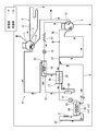
- FIG. 1 shows an embodiment in which the inside of the storage chamber CB of the ultra-low temperature storage DF of the embodiment illustrated in FIG. 9 is cooled to a temperature of ⁇ 80 ° C. or lower (internal temperature), for example, to an extremely low temperature of ⁇ 85 ° C. to ⁇ 86 ° C. 3 is a refrigerant circuit diagram of the refrigeration apparatus R.
- FIG. The compressors 1, 2 and the like constituting the refrigerant circuit of the refrigeration apparatus R are installed in the machine room MC located below the heat insulation box IB of the ultra-low temperature storage DF, and the evaporator (refrigerant pipe) 3 is insulated. It is assumed that the inner wall IL of the box IB is attached to the peripheral surface on the heat insulating material I side in a heat exchange manner.
- the refrigerant circuit of the refrigeration apparatus R includes a high-temperature side refrigerant circuit 4 and a low-temperature side refrigerant circuit 6 that constitute independent refrigerant closed circuits as multi-component (binary) single-stage refrigerant circuits.
- the compressor 1 constituting the high temperature side refrigerant circuit 4 is an electric compressor using a one-phase or three-phase AC power source.
- the refrigerant compressed by the compressor 1 is discharged to a refrigerant discharge pipe 7 connected to the discharge side of the compressor 1.
- the refrigerant discharge pipe 7 is connected to an auxiliary condenser (pre-condenser) 8.
- the auxiliary condenser 8 is connected to a frame pipe 9 for heating the opening edge of the storage chamber CB to prevent dew condensation.
- the refrigerant pipe exiting the frame pipe 9 is once connected to the oil cooler 11 of the compressor 1 and then connected to the oil cooler 12 of the compressor 2 constituting the low temperature side refrigerant circuit 6, and then the condenser. (Capacitor) 13 is connected.
- the refrigerant pipe exiting the condenser 13 is connected to a high temperature side dehydrator (dry core) 14 and a capillary tube 16 (decompressor).
- the dehydrator 14 is moisture removal means for removing moisture in the high temperature side refrigerant circuit 4.
- the capillary tube 16 is inserted into a part (18 ⁇ / b> A) of the suction pipe 18 that exits from the high-temperature side evaporator 19 of the cascade heat exchanger 17 and returns to the compressor 1.
- the capillary tube 16 is inserted into a pipe 18A which is a part of the suction pipe 18 on the outlet side of the evaporator 19 to form a double pipe structure.
- the refrigerant flowing through the capillary tube 16 that is the inner side of the double pipe 21 (hereinafter referred to as the double pipe structure), and the refrigerant from the evaporator 19 that flows through the pipe 18A that is the outer side thereof Is configured to be capable of heat exchange.
- the capillary tube 16 is inserted into the suction pipe 18 (pipe 18A) to form the double pipe structure 21, so that the refrigerant passing through the capillary tube 16 and the suction pipe 18 (pipe 18A) pass.
- the refrigerant that exchanges heat is exchanged by heat conduction that transmits the wall surface of the entire circumference of the capillary tube 16.
- the entire outer periphery of the pipe 18A of the double-pipe structure 21 is surrounded by a heat insulating material (not shown). Thereby, it becomes difficult to receive the influence of the heat from the outside, and the heat exchange capability between the refrigerant in the pipe 18A and the refrigerant in the capillary tube 16 can be further improved. Furthermore, in the capillary tube 16 that is the inner side of the double-pipe structure 21 and in the suction pipe 18 (pipe 18A) outside the capillary tube 16, the refrigerant is caused to flow in a counterflow. Thereby, the heat exchange capability in the double pipe structure 21 can be further improved.
- the refrigerant pipe exiting the capillary tube 16 is connected to a high temperature side evaporator 19 provided in heat exchange with the condenser 22 of the low temperature side refrigerant circuit 6.
- the high temperature side evaporator 19 constitutes a cascade heat exchanger 17 together with the condenser 22 of the low temperature side refrigerant circuit 6.
- the suction piping 18 which came out of the high temperature side evaporator 19 is connected to the suction side of the compressor 1 through the high temperature side header 23 and the said double pipe structure 21 one by one. That is, the high temperature side refrigerant circuit 4 is configured such that the compressor 1, the condenser 13, the capillary tube 16, the evaporator 19 and the like are connected in an annular shape in this order.
- the boiling point is about ⁇ 40 ° C. at atmospheric pressure, and this mixed refrigerant is condensed in the auxiliary condenser 8, the frame pipe 9, and the condenser 13, and is depressurized in the capillary tube 16 to constitute the cascade heat exchanger 17. It flows into the high temperature side evaporator 19 and evaporates. As a result, the cascade heat exchanger 17 has a temperature of about ⁇ 36 ° C.
- FIG. 1 Refrigerant Flow in High Temperature Side Refrigerating Circuit 4
- a broken line arrow indicates a flow of refrigerant circulating in the high temperature side refrigerant circuit 4. That is, the high-temperature gaseous refrigerant discharged from the compressor 1 is discharged from the hermetic container through the refrigerant discharge pipe 7, radiates heat in the auxiliary condenser 8 and the frame pipe 9, and then returns to the hermetic container again. 11 is passed. Thereby, the inside of an airtight container can be cooled with the refrigerant
- the high-temperature gaseous refrigerant is condensed in the oil cooler 12 and the condenser 13 of the compressor 2 of the low-temperature side refrigerant circuit 6 to be radiated and liquefied, and then the moisture contained in the dehydrator 14 is removed. It flows into the capillary tube 16 of the body 21.
- the refrigerant is heated by the heat passing through the suction pipe 18 (pipe 18 ⁇ / b> A) provided in the entire circumference of the capillary tube 16 and the wall surface of the entire circumference of the capillary tube 16.
- the pressure is reduced while the temperature is further reduced, and the vapor flows into the evaporator 19.
- the refrigerant evaporates by absorbing heat from the refrigerant flowing in the condenser 22 of the cascade heat exchanger 17. Thereby, the refrigerant flowing through the condenser 22 is cooled.
- the refrigerant evaporated in the evaporator 19 exits from the high-temperature side evaporator 19 via the suction pipe 18 and flows into the double-pipe structure 21 through the high-temperature side header 23, and the capillary described above. After exchanging heat with the refrigerant flowing in the tube 16, the refrigerant returns to the compressor 1.
- the compressor 2 constituting the low-temperature side refrigerant circuit 6 is an electric compressor that uses a one-phase or three-phase AC power source, like the compressor 1 of the high-temperature side refrigerant circuit 4.
- the refrigerant discharge pipe 26 of the compressor 2 reaches the internal heat exchanger 27.
- This internal heat exchanger 27 is compressed by the compressor 2, evaporates in the evaporator 3 with the high-pressure side refrigerant on the way to the capillary tube 28 (decompressor), and evaporates in the evaporator 3. It is a heat exchanger for exchanging heat.
- the high-pressure side refrigerant pipe that has passed through the internal heat exchanger 27 is connected to the condenser 22.
- the condenser 22 constitutes the cascade heat exchanger 17 together with the high temperature side evaporator 19 of the high temperature side refrigerant circuit 4 as described above.
- the refrigerant pipe exiting from the condenser 22 is connected to the low temperature side dehydrator (dry core) 31 and the capillary tube 28.
- the dehydrator 31 is moisture removal means for removing moisture in the low temperature side refrigerant circuit 6.
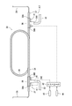
- the capillary tube 28 is inserted into a main pipe 34 of a double-pipe structure 33 described later, which is a part of a suction pipe 32 that exits the evaporator 3 and returns to the compressor 2.
- the double pipe structure 21 described above is also the same.
- the straight tubular capillary tube 28 is inserted into a straight tubular main tube 34 having a diameter larger than that of the capillary tube 28 to form a double tube.
- the double pipe is spirally wound in a plurality of stages. At this time, winding is performed so that the center of the axis of the main tube 34 and the center of the axis of the capillary tube 28 are as close as possible to form a spiral double tube. As a result, a uniform gap is formed as consistently as possible between the inner wall surface of the main pipe 34 and the outer wall surface of the capillary tube 28.
- the double tube is wound in a plurality of stages to form a spiral double tube structure, so that the length of the capillary tube 28 is sufficiently secured, and the double tube structure 33 is provided. It is possible to achieve downsizing while sufficiently securing the heat exchange part.
- the other side end 36B of the connection pipe 36 formed by welding one end of the end pipe 37 to one side end 36A of the T-shaped pipe in the embodiment is attached to both ends of the main pipe 34.
- the suction pipe 32 connected to the outlet side of the evaporator 3 is connected to the lower end 36C of the T-shaped pipe of one connection pipe 36, and this connection portion is welded.
- the suction pipe 32 reaching the internal heat exchanger 27 is connected to the lower end 36C of the T-shaped pipe of the connection pipe 36 attached to the other end of the main pipe 34, and this connection portion is welded.
- the outer periphery of the double pipe structure 33 which concerns is enclosed by the heat insulating material which is not shown in figure.
- the capillary tube 28 is inserted into the suction pipe 32 (main pipe 34 and connection pipe 36) to form the double pipe structure 33, whereby the refrigerant passing through the capillary tube 28 and the suction pipe 32 (main pipe 34).
- the refrigerant passing through the inside exchanges heat by heat conduction transmitted through the wall surface of the entire circumference of the capillary tube 28.
- the heat exchange capability between the refrigerant in the main pipe 34 and the refrigerant in the capillary tube 28 is further increased. It can be further improved. Furthermore, in the capillary tube 28 inside the double-pipe structure 33 and in the suction pipe 32 (main pipe 34) outside the capillary tube 28, the refrigerant is caused to flow in a counter flow. Thereby, the heat exchange capability in the double pipe structure 33 can be further improved.
- Such a double-pipe structure 33 is housed in a heat insulating material I on the back side of the inner box IL of the ultra-low temperature storage DF as shown in FIG.
- the heat insulating material surrounding the double pipe structure 33 is not shown.
- the IS shown in FIG. 9 is a heat insulating structure formed by surrounding the above-described cascade heat exchanger 17 and the like with a heat insulating material.
- the heat insulating material on the back side of the inner box IL is adjacent to the double pipe structure 33.
- I is stored in I.
- the suction pipe 32 exiting the double pipe structure 33 is connected to the suction side of the compressor 2 via the internal heat exchanger 27. That is, the low temperature side refrigerant circuit 6 is also configured such that the compressor 2, the condenser 22, the capillary tube 28, the evaporator 3 and the like are annularly connected in this order.
- the boiling point of ethane (R170) is -88.8 ° C
- GWP is 3
- the boiling point of carbon dioxide (R744) is -78.4 ° C
- GWP is 1
- the boiling point of difluoromethane (R32) is -51.7 ° C
- GWP is The refrigerant composition in which these are mixed has a boiling point of ⁇ 86 ° C. or lower due to contribution of the improvement of the refrigerating capacity by carbon dioxide (R744).
- the boiling point of carbon dioxide (R744) is ⁇ 78.4 ° C., it does not directly contribute to the cooling action in the evaporator 3 for an evaporation temperature of ⁇ 85 ° C. to ⁇ 86 ° C., but the GWP is 1 Therefore, by mixing this carbon dioxide (R744), the GWP of the refrigerant sealed in the low temperature side refrigerant circuit 6 can be reduced.
- the thermal conductivity it is possible to improve the refrigerating capacity, increase the density of the refrigerant sucked into the compressor 2, and azeotrope with ethane (R170) as the first refrigerant. Since the effect can also be expected, the refrigeration capacity can be further improved.
- difluoromethane (R32) is a second refrigerant that has solubility with carbon dioxide (R744) at a temperature lower than the boiling point of carbon dioxide (R744) and that has high solubility.
- the refrigerant is heated by the heat passing through the suction pipe 32 (main pipe 34) provided on the entire circumference of the capillary tube 28 and the wall surface of the entire circumference of the capillary tube 28.
- the pressure is reduced while the temperature is further lowered and flows into the evaporator 3.
- ethane (R170) which is the first refrigerant, takes heat from the surroundings and evaporates.
- ethane (R170) of the first refrigerant evaporates in the evaporator 3, thereby exerting a cooling action and cooling the periphery of the evaporator 3 to an extremely low temperature of -88 ° C to -90 ° C.
- the evaporator (refrigerant pipe) 3 is configured to be heat-heated along the heat insulating material I side of the inner box IL of the heat insulating box IB. It is possible to set the inside temperature of the storage room CB of the storage DF to ⁇ 80 ° C. or lower.
- the refrigerant evaporated in the evaporator 3 then exits the evaporator 3 through the suction pipe 32 and returns to the compressor 2 through the double pipe structure 33 and the internal heat exchanger 27 described above.
- the double pipe structure 33 is formed.
- the performance can be improved by improving the efficiency of heat exchange between the refrigerant and the refrigerant in the capillary tube 28.
- the capillary tube 28 is inserted into the main pipe 34 of the suction pipe 32 immediately after exiting the evaporator 3 to form a double-pipe structure 33, and heat exchange is possible by heat conduction that transmits the entire wall surface of the capillary tube 28.
- the heat exchange efficiency can be further improved by inserting the capillary tube 28 and surrounding the double-pipe structure 33 with a heat insulating material. Furthermore, the heat exchange capability can be further improved by making the flow of the refrigerant in the capillary tube 28 and the flow of the refrigerant passing through the main pipe 34 outside the capillary tube 28 counter flow.
- the capillary tube 16 as the pressure reducing means of the high-temperature side refrigerant circuit 4 is also a double-pipe structure 21 like the capillary tube 28 of the low-temperature side refrigerant circuit 6, and the double-pipe structure 21 is insulated. Surrounded by wood. Furthermore, the flow of the refrigerant is opposed to the inside of the capillary tube 16 that is inside the double-pipe structure 21 and the suction pipe 18 (pipe 18A) outside the capillary tube 16. Thereby, the refrigerant in the capillary tube 16 can be efficiently cooled by the return refrigerant from the evaporator 19. Thereby, the heat exchange efficiency can be further improved to further improve the performance. In general, it is possible to realize the refrigeration apparatus R that can efficiently cool the inside of the ultra-low temperature storage DF (inside the storage chamber CB) to a desired cryogenic temperature.
- each connection pipe constituted by a T-shaped tube In the portion 36 the refrigerant flow direction is changed to a substantially right angle along the shape (indicated by X1 and X2 in FIGS. 1 and 2). Therefore, when the refrigerant passes through the connection pipe 36, pressure loss is apt to occur.
- the boiling point of carbon dioxide (R744) is ⁇ 78.4 ° C., which is higher than that of ethane (R170), which is the first refrigerant. Then, it comes out to the suction pipe 32 as wet steam. Therefore, the refrigerant exiting the evaporator 3 has a very high ratio of carbon dioxide (R744) and an extremely low temperature of ⁇ 85 ° C. or lower. is there.
- FIG. 4 shows the internal temperature (center in the height direction) when the ratio (wt%) of carbon dioxide (R744) to the total weight of the refrigerant composition enclosed in the low-temperature side refrigerant circuit 6 is changed stepwise. )) And the temperature at the inlet of the evaporator 3 (evaporator inlet temperature) Eva-In (outside air temperature + 30 ° C.).
- ethane (R170) was 100 (wt%)
- the evaporator inlet temperature Eva-In was ⁇ 91.2 ° C.
- the internal temperature 1 / 2H was ⁇ 86.0 ° C.
- R32 is dissolved and removed.
- the composition at this time is 81.9 (wt%) for ethane (R170), 15.0 (wt%) for carbon dioxide (R744), and 3.1 (wt%) for difluoromethane (R32).
- the reason why the ratio of ethane (R170) and carbon dioxide (R744) to the total weight is decreased is because difluoromethane (R32) is contained.
- FIG. 5 summarizes the status of the conversion of carbon dioxide (R744) to dry ice and its elimination with respect to the ratio of the refrigerant composition containing ethane (R170), carbon dioxide (R744), and difluoromethane (R32).
- the horizontal axis represents the ratio (wt%) of carbon dioxide (R744) to the total weight
- the vertical axis represents the evaporator inlet temperature Eva-In.
- the upper stage and the lower stage of FIG. 5 are plots of two experimental results obtained by changing the outside air temperature and / or the condition of the capillary tube.
- each plot (1) to (6) in FIG. 5 shows that only ethane (R170) is added to the refrigerating apparatus R of the embodiment, and difluoromethane (R32) is 0 (wt%) in ethane (R170) and carbon dioxide (R744). 3.1 (wt%), 6.1 (wt%), 8.9 (wt%), and 23.6 (wt%) are respectively added, and (7) to (13) are as described above.
- difluoromethane (R32) is added to ethane (R170) and carbon dioxide (R744) at 0 (wt%), 4.0 (wt%), 15.8 (wt%). ), 11.3 (wt%), 18.5 (wt%), and 27.5 (wt%) are added.
- the solid line L1 in FIG. 5 indicates the limit at which dry ice is not generated when carbon dioxide (R744) is mixed with ethane (R170). For example, when the evaporator inlet temperature Eva-In is -91 ° C. It means that dry ice does not occur even when carbon dioxide (R744) is mixed up to 14 (wt%).
- the range from the solid line L1 to the broken line L2 indicates a region where dry ice is generated. When the evaporator inlet temperature Eva-In is ⁇ 91 ° C., for example, when carbon dioxide (R744) is added up to 19 wt%, the dry ice is generated. It means that ice is generated.
- the solid line L3 shows the case where 8.9 (wt%) of difluoromethane (R32) is added to eliminate dry ice, and the internal temperature 1 / 2H and the evaporator inlet temperature Eva-In are stabilized.
- the proportion of carbon dioxide (R744) decreases to about 16.4 (wt%) by the amount of difluoromethane (R32).
- a solid line L4 in FIG. 5 shows a case where difluoromethane (R32) is added up to 23.6 (wt%) to eliminate dry ice and the internal temperature 1 / 2H and the evaporator inlet temperature Eva-In are stabilized.
- difluoromethane (R32) is added up to 23.6 (wt%) to eliminate dry ice and the internal temperature 1 / 2H and the evaporator inlet temperature Eva-In are stabilized.
- carbon dioxide (R744) can be mixed to more than 20 (wt%) to 25 (wt%) (not dry iced) ) That is, when difluoromethane (R32) is not added, the asterisk plot (15) becomes the plot (6) and moves to the solid line L4, which means that dry ice formation can be prevented.
- the solid line L5 in the lower part shows that difluoromethane (R32) is added to 4.0 (wt%) to eliminate dry ice, the internal temperature 1 / 2H and the evaporator inlet temperature Eva- In the case where In is stabilized, L6 is increased to 18.5 (wt%), L7 is increased to 27.5 (wt%) to eliminate dry ice, the internal temperature 1 / 2H and the evaporator inlet temperature Eva- The case where In was stabilized is shown.
- ethane (R170) is used as the first refrigerant, and ethane (R170), carbon dioxide (R744), and carbon dioxide (R744) at a temperature lower than the boiling point of carbon dioxide (R744).
- the refrigerant composition includes difluoromethane (R32) having solubility, the difluoromethane (R32) is added at a ratio capable of preventing carbon dioxide (R744) from becoming dry ice as described above. Even when more than 20% of R744) is added to the total mass, the generation of dry ice at the locations X1 and X2 where the pressure loss of the double-pipe structure 33 of the low-temperature side refrigerant circuit 6 is likely to occur is eliminated and stable. It is possible to exert the frozen effect.
- 2-Tetrafluoroethane (R134a) is also a second refrigerant having solubility with carbon dioxide (R744) at a temperature lower than the boiling point of carbon dioxide (R744).
- 1,1,1,2-tetrafluoroethane (R134a) has a boiling point of ⁇ 26.1 ° C. and a GWP of 1300. Moreover, it is nonflammable, and the effect of making the mixed refrigerant incombustible can also be expected.
- FIG. 6 shows the internal temperature 1 / when the ratio (wt%) of carbon dioxide (R744) to the total weight of the refrigerant composition enclosed in the low-temperature refrigerant circuit 6 is changed. It shows a change in 2H and the evaporator inlet temperature Eva-In (similarly outside air temperature + 30 ° C.).
- ethane (R170) was 100 (wt%)
- the evaporator inlet temperature Eva-In was ⁇ 91.8 ° C.
- the internal temperature 1 / 2H was ⁇ 86.0 ° C.
- the refrigerant composition is difluoroethylene (R1132a), carbon dioxide (R744), and difluoromethane (R32), and this composition is a case where dry ice conversion of carbon dioxide is eliminated.
- Difluoroethylene (R1132a) has a boiling point of ⁇ 83.5 ° C. and a GWP of 10.
- FIG. 7 shows the interior when the ratio (wt%) of carbon dioxide (R744) to the total weight of the refrigerant composition enclosed in the low-temperature refrigerant circuit 6 is changed as in the case of FIGS. It shows a change in the temperature (center temperature in the height direction) 1 / 2H and the temperature at the inlet of the evaporator 3 (evaporator inlet temperature) Eva-In.
- this is another experimental result obtained by changing the outside air temperature and / or the condition of the capillary tube, and shows the same tendency.
- the evaporator outlet temperature Eva-Out decreases to -92.2 ° C and the internal temperature 1 / 2H decreases to -90.0 ° C.
- the evaporator inlet temperature Eva-In increased to -97.0 ° C. Since the evaporator inlet temperature Eva-In starts to rise, it can be seen that dry ice is starting to be generated at the locations X1 and X2 where pressure loss is likely to occur in the connection pipe 36.
- ethane (R170) and difluoroethylene (R1132a) have been described as examples of the first refrigerant having a boiling point of ⁇ 89.0 ° C. or higher and ⁇ 78.1 ° C. or lower.
- a mixed refrigerant of ethylene (R1132a) and hexafluoroethane (R116) or a mixed refrigerant of difluoroethylene (R1132a) and ethane (R170) is also effective.
- the present invention is effective.
- difluoromethane (R32) and 1,1,1,2-tetrafluoroethane are used as the second refrigerant having solubility with carbon dioxide (R744) at a temperature lower than the boiling point of carbon dioxide (R744).
- R134a has been described as an example, but not limited thereto, n-pentane (R600), isobutane (R600a), 1,1,1,2,3-pentafluoropentene (HFO-1234ze), 1,1, 1,2-tetrafluoropentene (HFO-1234yf) is also soluble as carbon dioxide (R744) at a temperature lower than the boiling point of carbon dioxide (R744), and thus can be employed as the second refrigerant.
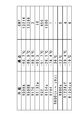
- the boiling point and GWP of each refrigerant are shown in FIG.
- the electric heater 41 is attached to the double-pipe structure 33 in which carbon dioxide (R744) is converted to dry ice.
- the electric heater 41 is wound corresponding to the locations X1 and X2 of the connection pipe 36 where the pressure loss is likely to occur.
- reference numeral 42 denotes a controller as a control means for controlling operation of the ultra-low temperature storage DF, and an electric heater 41 is connected to an output of the controller 42.
- the input of the controller 42 includes the internal temperature sensor 43 that detects the internal temperature of the storage chamber CB (the target region cooled by the refrigeration effect by the evaporator 3), and the temperature of the double-pipe structure 33. The output of the double pipe structure temperature sensor 44 to be detected is connected.
- the controller 41 energizes the electric heater 41 and places the double-pipe structure 33.
- X1 and X2 are heated and rise to an upper limit value having a predetermined value and a predetermined differential, energization of the electric heater 41 is stopped.
- This predetermined value is a temperature at which carbon dioxide (R744) is converted to dry ice at the locations X1 and X2 of the connection pipe 36.
- the internal temperature of the storage chamber CB detected by the internal temperature sensor 43 rises (predetermined value) with respect to the set value.
- the electric heater 41 may be energized (then, when the internal temperature is lowered to the set value, or when the temperature of the double-pipe structure 33 is raised to the upper limit value, Stop energization).
- the conversion of carbon dioxide (R744) into dry ice more accurately and to control the power supply to the electric heater 41 accurately.
- connection pipe 36 is configured by a T-shaped pipe.
- the present invention is not limited to this, and the present invention is also effective in the case of a connection pipe having other shapes that are liable to cause pressure loss, such as a Y shape or an L shape. It is.
- the numerical values shown in each of the above examples are examples in the case of the ultra-low temperature storage DF experimentally measured, and may be appropriately set according to the capacity and the like.
- the present invention has been described with a so-called binary refrigeration apparatus.
- the present invention is not limited to this.
- the present invention is also effective for multiple refrigeration apparatuses larger than the original.
Landscapes
- Engineering & Computer Science (AREA)
- Chemical & Material Sciences (AREA)
- Physics & Mathematics (AREA)
- Thermal Sciences (AREA)
- Chemical Kinetics & Catalysis (AREA)
- General Engineering & Computer Science (AREA)
- Mechanical Engineering (AREA)
- Combustion & Propulsion (AREA)
- Materials Engineering (AREA)
- Organic Chemistry (AREA)
- Cooling Or The Like Of Semiconductors Or Solid State Devices (AREA)
- Organic Low-Molecular-Weight Compounds And Preparation Thereof (AREA)
- Devices That Are Associated With Refrigeration Equipment (AREA)
- Lubricants (AREA)
Abstract
Description
図1は、図9に例示する実施例の超低温貯蔵庫DFの貯蔵室CB内を-80℃以下の温度(庫内温度)、例えば-85℃乃至-86℃の極低温に冷却する実施例の冷凍装置Rの冷媒回路図である。尚、冷凍装置Rの冷媒回路を構成する圧縮機1、2等は超低温貯蔵庫DFの断熱箱体IBの下部に位置する機械室MCに設置されており、蒸発器(冷媒配管)3は、断熱箱体IBの内箱ILの断熱材I側の周面に交熱的に取り付けられているものとする。
本実施例の冷凍装置Rの冷媒回路は、多元(二元)単段の冷媒回路として、それぞれ独立した冷媒閉回路を構成する高温側冷媒回路4と低温側冷媒回路6により構成されている。高温側冷媒回路4を構成する圧縮機1は、一相若しくは三相交流電源を用いる電動圧縮機である。この圧縮機1で圧縮された冷媒は、圧縮機1の吐出側に接続された冷媒吐出管7に吐出される。この冷媒吐出管7は、補助凝縮器(プレコンデンサ)8に接続される。この補助凝縮器8は前記貯蔵室CBの開口縁を加熱して露付きを防止するためのフレームパイプ9に接続される。
当該高温側冷媒回路4内には、ジフロロメタン(R32)/ペンタフロロエタン(R125)/1,1,1,2-テトラフロロエタン(R134a)共沸混合物(R407D)、或いは、ペンタフロロエタン(R125)/1,1,1-トリフロロエタン(R143a)/1,1,1,2-テトラフロロエタン(R134a)共沸混合物(R404A)、或いは、GWPが1500以下である冷媒組成物として、ジフロロメタン(R32)、ペンタフロロエタン(R125)、1,1,1,2-テトラフロロエタン(R134a)、1,1,1-トリフロロエタン(R143a)の冷媒群に、1,1,1,2,3-ペンタフロロペンテン(HFO-1234ze、GWP6、沸点-19℃)を含むフッ化炭化水素混合冷媒を含む混合冷媒、或いは、同様にGWPが1500以下である冷媒組成物として、ジフロロメタン(R32)、ペンタフロロエタン(R125)、1,1,1,2-テトラフロロエタン(R134a)、1,1,1-トリフロロエタン(R143a)の冷媒群に、1,1,1,2-テトラフロロペンテン(HFO-1234yf、GWP4、沸点-29.4℃)を含むフッ化炭化水素混合冷媒を含む混合冷媒が封入される。
図1において、破線矢印は高温側冷媒回路4を循環する冷媒の流れを示している。即ち、圧縮機1から吐出された高温ガス状冷媒は、冷媒吐出管7を介して密閉容器から吐出され、補助凝縮器8、フレームパイプ9にて放熱した後、再度密閉容器内に戻りオイルクーラ11を通過する。これにより、密閉容器内を温度低下した冷媒により冷却することができる。そして、係る高温ガス状冷媒は、低温側冷媒回路6の圧縮機2のオイルクーラ12、凝縮器13にて凝縮されて放熱液化した後、デハイドレータ14で含有する水分が除去され、二重管構造体21のキャピラリチューブ16に流入する。
他方、低温側冷媒回路6を構成する圧縮機2は、高温側冷媒回路4の圧縮機1と同様に一相若しくは三相交流電源を用いる電動圧縮機である。この圧縮機2の冷媒吐出管26は、内部熱交換器27に至る。この内部熱交換器27は、圧縮機2で圧縮され、キャピラリチューブ28(減圧器)に向かう途中の高圧側冷媒と蒸発器3にて蒸発し、圧縮機2に戻る途中の低圧側冷媒とを熱交換するための熱交換器である。
具体的な構造が図2に示されている。即ち、蒸発器3の出口側であって、且つ、内部熱交換器27の上流側に位置する吸込配管32の一部(蒸発器3の直後)である主管34内に、キャピラリチューブ28を挿通して図2に示すように二重管構造体33を構成している。係る二重管構造により、二重管構造体33の内側となるキャピラリチューブ28を流れる冷媒と、その外側となる主管34を流れる蒸発器3からの冷媒とが熱交換可能に構成されている。
当該低温側冷媒回路6内には、実施例では第1冷媒としてのエタン(R170)と、これに混合される冷媒としての二酸化炭素(R744)、及び、ジフロロメタン(R32)を含む混合冷媒を封入する。各冷媒の沸点及びGWPは図3に示されている。エタン(R170)の沸点は-88.8℃、GWPは3、二酸化炭素(R744)の沸点は-78.4℃、GWPは1、ジフロロメタン(R32)の沸点は-51.7℃、GWPは650であり、これらを混合した冷媒組成物の沸点は、二酸化炭素(R744)による冷凍能力向上も寄与して-86℃以下となる。
図1において、実線矢印は低温側冷媒回路6を循環する冷媒の流れを示している。具体的に当該低温側冷媒回路6における冷媒の流れを説明すると、圧縮機2から吐出された高温ガス状冷媒は、冷媒吐出管26を介して密閉容器から吐出され、内部熱交換器27、凝縮器22にて凝縮されて放熱液化した後、低温側デハイドレータ31で含有する水分が除去され、キャピラリチューブ28に流入する。
ここで、前述した低温側冷媒回路6の二重管構造体33では、T字管で構成される各接続配管36の部分で、その形状に沿って冷媒の流通方向が略直角に変更されるかたちとなる(図1、図2にX1、X2で示す)。そのため、この接続配管36を冷媒が通過する際、どうしても圧力損失が生じ易い。
図4は低温側冷媒回路6に封入される冷媒組成物の総重量に対する二酸化炭素(R744)の割合(wt%)を段階的に変化させた場合の庫内温度(高さ方向の庫内中央の温度)1/2Hと蒸発器3の入口の温度(蒸発器入口温度)Eva-Inの変化を示している(外気温度+30℃)。エタン(R170)が100(wt%)のときに蒸発器入口温度Eva-Inは-91.2℃、庫内温度1/2Hは-86.0℃であった。そこに二酸化炭素(R744)を4.6(wt%)混合すると、蒸発器入口温度Eva-Inは-92.2℃、庫内温度1/2Hは-86.1℃に下がり、更に、混合する二酸化炭素(R744)を8.8(wt%)に増やすと、蒸発器入口温度Eva-Inは-93.9℃、庫内温度1/2Hは-86.3℃に下がった。
次に、係る組成、即ち、エタン(R170)が84.6(wt%)、二酸化炭素(R744)が15.4(wt%)の組成に対して、ジフロロメタン(R32)を3.1(wt%)混合した場合、各温度は安定して蒸発器入口温度Eva-Inは-91.2℃、庫内温度1/2Hは-86.8℃となった。これは接続配管36の箇所X1、X2部分に詰まったドライアイスを、二酸化炭素(R744)の沸点より低い温度において二酸化炭素(R744)と溶解性を有し、且つ、その溶解性が高いジフロロメタン(R32)が溶かして除去したことを表している。このときの組成は、エタン(R170)が81.9(wt%)、二酸化炭素(R744)が15.0(wt%)、ジフロロメタン(R32)が3.1(wt%)である。総重量に対するエタン(R170)と二酸化炭素(R744)の割合が減少しているのは、ジフロロメタン(R32)が入ったためである。
次に、上記低温側冷媒回路6にエタン(R170)と二酸化炭素(R744)に加えて、1,1,1,2-テトラフロロエタン(R134a)を混合してドライアイス化を解消した場合を説明する。前述の実施例では二酸化炭素(R744)の沸点より低い温度において二酸化炭素(R744)との溶解性を有する第2冷媒としてジフロロメタン(R32)を用いたが、この実施例の1,1,1,2-テトラフロロエタン(R134a)も二酸化炭素(R744)の沸点より低い温度において二酸化炭素(R744)との溶解性を有する第2冷媒である。尚、1,1,1,2-テトラフロロエタン(R134a)の沸点は-26.1℃、GWPは1300である。また、不燃性でもあり、混合冷媒の不燃化の効果も期待できる。
次に、係る組成、即ち、エタン(R170)が85.2(wt%)、二酸化炭素(R744)が14.8(wt%)の組成に対して、1,1,1,2-テトラフロロエタン(R134a)を4.6(wt%)混合した場合、各温度は安定して蒸発器入口温度Eva-Inは-92.9℃、庫内温度1/2Hは-86.5℃となった。これは接続配管36の箇所X1、X2部分に詰まったドライアイスを、二酸化炭素(R744)と溶解性を有する1,1,1,2-テトラフロロエタン(R134a)が溶かして除去したことを表している。このときの組成は、エタン(R170)が81.3(wt%)、二酸化炭素(R744)が14.1(wt%)、1,1,1,2-テトラフロロエタン(R134a)が4.6(wt%)である。総重量に対するエタン(R170)と二酸化炭素(R744)の割合が減少しているのは、1,1,1,2-テトラフロロエタン(R134a)が4.6(wt%)が入ったためである。
次に、上記低温側冷媒回路6にエタン(R170)の代わりに第1冷媒としてジフルオロエチレン(R1132a)を封入した場合について説明する。この場合の冷媒組成物は、ジフルオロエチレン(R1132a)と二酸化炭素(R744)とジフロロメタン(R32)となり、この組成によって二酸化炭素のドライアイス化を解消した場合である。尚、ジフルオロエチレン(R1132a)の沸点は-83.5℃、GWPは10である。
次に、係る組成、即ち、ジフルオロエチレン(R1132a)が79.2(wt%)、二酸化炭素(R744)が20.8(wt%)の組成に対して、ジフロロメタン(R32)を1.1(wt%)混合した場合、各温度は安定して蒸発器入口温度Eva-Inは-91.6℃、蒸発器出口温度Eva-Outは-91.4℃、庫内温度1/2Hは-89.3℃となった。これは接続配管36の箇所X1、X2部分に詰まったドライアイスを、二酸化炭素(R744)と溶解性が高いジフロロメタン(R32)が溶かして除去したことを表している。このときの組成は、ジフルオロエチレン(R1132a)が78.3(wt%)、二酸化炭素(R744)が20.6(wt%)、ジフロロメタン(R32)が1.1(wt%)である。総重量に対するジフルオロエチレン(R1132a)と二酸化炭素(R744)の割合が減少しているのは、ジフロロメタン(R32)が入ったためである。
3、19 蒸発器
4 高温側冷媒回路
6 低温側冷媒回路
13、22 凝縮器
16、28 キャピラリチューブ(減圧器)
17 カスケード熱交換器
32 吸込配管
33 二重管構造体
34 主管
36 接続配管
DF 超低温貯蔵庫
R 冷凍装置
Claims (6)
- 圧縮機、凝縮器、減圧器及び蒸発器がこの順で環状に接続されてなる冷媒回路を備え、該冷媒回路中の冷媒として、
沸点が-89.0℃以上、-78.1℃以下の極低温域の冷媒を第1冷媒と、
二酸化炭素(R744)と、
該二酸化炭素(R744)の沸点より低い温度において該二酸化炭素(R744)との溶解性を有する第2冷媒と、
を含む冷媒組成物を使用したことを特徴とする冷凍装置。 - 前記第1冷媒は、
ジフルオロエチレン(R1132a)、又は、
ジフルオロエチレン(R1132a)とヘキサフルオロエタン(R116)との混合冷媒、又は、
ジフルオロエチレン(R1132a)とエタン(R170)との混合冷媒、又は、
エタン(R170)、又は、
エタン(R170)とヘキサフルオロエタン(R116)の混合冷媒、又は、
トリフルオロメタン(R23)を39質量%、ヘキサフルオロエタン(R116)を61質量%混合した共沸混合物(R508A、沸点-85.7℃)、又は、
トリフルオロメタン(R23)を46質量%、ヘキサフルオロエタン(R116)を54質量%混合した共沸混合物(R508B、沸点-86.9℃)、
を含むことを特徴とする請求項1に記載の冷凍装置。 - 前記第2冷媒は、
ジフロロメタン(R32)、又は、
1,1,1,2-テトラフロロエタン(R134a)、又は、
n-ペンタン(R600)、又は、
イソブタン(R600a)、又は、
1,1,1,2,3-ペンタフロロペンテン(HFO-1234ze)、又は、
1,1,1,2-テトラフロロペンテン(HFO-1234yf)
を含むことを特徴とする請求項1又は請求項2に記載の冷凍装置。 - 前記二酸化炭素(R744)を、前記冷媒組成物の総質量に対して20%より多く加えたことを特徴とする請求項1乃至請求項3のうちの何れかに記載の冷凍装置。
- 前記第2冷媒を、前記二酸化炭素(R744)のドライアイス化を防止可能な割合で加えたことを特徴とする請求項1乃至請求項4のうちの何れかに記載の冷凍装置。
- 前記冷媒回路は、それぞれ圧縮機から吐出された冷媒を凝縮した後、キャピラリチューブで減圧し、蒸発器にて蒸発させて冷却作用を発揮する独立した冷媒閉回路を構成する高温側冷媒回路と低温側冷媒回路とを備え、前記高温側冷媒回路の蒸発器と前記低温側冷媒回路の凝縮器とでカスケード熱交換器が構成され、前記低温側冷媒回路の蒸発器にて最終的な冷却作用を発揮する前記低温側冷媒回路中の冷媒として、前記冷媒組成物を使用したことを特徴とする請求項1乃至請求項5のうちの何れかに記載の冷凍装置。
Priority Applications (4)
| Application Number | Priority Date | Filing Date | Title |
|---|---|---|---|
| EP14848428.0A EP3051227B1 (en) | 2013-09-27 | 2014-09-22 | Refrigerating device |
| JP2015538901A JP5963969B2 (ja) | 2013-09-27 | 2014-09-22 | 冷凍装置 |
| CN201480052595.3A CN105579790B (zh) | 2013-09-27 | 2014-09-22 | 冷冻装置 |
| US15/057,950 US20160178246A1 (en) | 2013-09-27 | 2016-03-01 | Refrigeration apparatus |
Applications Claiming Priority (2)
| Application Number | Priority Date | Filing Date | Title |
|---|---|---|---|
| JP2013201818 | 2013-09-27 | ||
| JP2013-201818 | 2013-09-27 |
Related Child Applications (1)
| Application Number | Title | Priority Date | Filing Date |
|---|---|---|---|
| US15/057,950 Continuation US20160178246A1 (en) | 2013-09-27 | 2016-03-01 | Refrigeration apparatus |
Publications (1)
| Publication Number | Publication Date |
|---|---|
| WO2015045354A1 true WO2015045354A1 (ja) | 2015-04-02 |
Family
ID=52742526
Family Applications (1)
| Application Number | Title | Priority Date | Filing Date |
|---|---|---|---|
| PCT/JP2014/004849 Ceased WO2015045354A1 (ja) | 2013-09-27 | 2014-09-22 | 冷凍装置 |
Country Status (5)
| Country | Link |
|---|---|
| US (1) | US20160178246A1 (ja) |
| EP (1) | EP3051227B1 (ja) |
| JP (1) | JP5963969B2 (ja) |
| CN (1) | CN105579790B (ja) |
| WO (1) | WO2015045354A1 (ja) |
Cited By (11)
| Publication number | Priority date | Publication date | Assignee | Title |
|---|---|---|---|---|
| KR20200051588A (ko) * | 2017-09-08 | 2020-05-13 | 바이스 움벨트테크닉 게엠베하 | 냉매 |
| KR20210045402A (ko) * | 2018-08-14 | 2021-04-26 | 멕시켐 플루어 소시에다드 아노니마 데 카피탈 바리아블레 | 냉매 조성물 및 그 용도 |
| KR20210045398A (ko) * | 2018-08-14 | 2021-04-26 | 멕시켐 플루어 소시에다드 아노니마 데 카피탈 바리아블레 | 냉매 조성물 |
| US20210199357A1 (en) * | 2018-09-11 | 2021-07-01 | Phc Holdings Corporation | Cooling device |
| JP2021178958A (ja) * | 2020-05-14 | 2021-11-18 | バイス テヒニク ゲゼルシャフト ミット ベシュレンクテル ハフツング | 冷媒 |
| KR20220137897A (ko) * | 2020-02-14 | 2022-10-12 | 멕시켐 플루어 소시에다드 아노니마 데 카피탈 바리아블레 | 조성물 |
| KR20220137898A (ko) * | 2020-02-14 | 2022-10-12 | 멕시켐 플루어 소시에다드 아노니마 데 카피탈 바리아블레 | 조성물 |
| WO2023285652A1 (en) * | 2021-07-16 | 2023-01-19 | B Medical Systems S.à r.l. | Medical contact shock freezer |
| JPWO2023012960A1 (ja) * | 2021-08-05 | 2023-02-09 | ||
| WO2023012961A1 (ja) * | 2021-08-05 | 2023-02-09 | 三菱電機株式会社 | 冷凍サイクル装置、及び冷凍サイクル装置の制御方法 |
| JP2024049377A (ja) * | 2022-09-28 | 2024-04-09 | ダイキン工業株式会社 | ジフルオロエチレンの製造方法 |
Families Citing this family (16)
| Publication number | Priority date | Publication date | Assignee | Title |
|---|---|---|---|---|
| GB2516694B (en) * | 2013-07-30 | 2016-09-07 | Mexichem Amanco Holding Sa | Heat transfer compositions |
| DE102016204378B4 (de) * | 2016-03-16 | 2025-11-27 | Weiss Umwelttechnik Gmbh | Prüfkammer |
| JP6720752B2 (ja) * | 2016-07-25 | 2020-07-08 | 富士通株式会社 | 液浸冷却装置、液浸冷却システム、及び液浸冷却装置の制御方法 |
| DE102017216361A1 (de) * | 2017-09-14 | 2019-03-14 | Weiss Umwelttechnik Gmbh | Verfahren zur Konditionierung von Luft |
| CN111511874A (zh) * | 2017-12-18 | 2020-08-07 | 大金工业株式会社 | 制冷循环装置 |
| US11352535B2 (en) * | 2018-04-25 | 2022-06-07 | Daikin Industries, Ltd. | Composition containing coolant, heat transfer medium and heat cycle system |
| JP6642756B2 (ja) * | 2018-04-25 | 2020-02-12 | ダイキン工業株式会社 | 冷媒を含有する組成物、熱移動媒体及び熱サイクルシステム |
| CN109135677B (zh) * | 2018-08-22 | 2020-09-18 | 安徽工业大学 | 一种co2/r170共沸制冷剂 |
| KR102518852B1 (ko) * | 2018-11-07 | 2023-04-10 | 신와 콘트롤즈 가부시키가이샤 | 유체 온조 시스템 및 냉동 장치 |
| GB201901890D0 (en) * | 2019-02-11 | 2019-04-03 | Mexichem Fluor Sa De Cv | Compositions |
| DE102019105676B4 (de) * | 2019-03-06 | 2021-05-06 | Weiss Umwelttechnik Gmbh | Kältemittel und dessen Verwendung |
| WO2021029556A1 (ko) * | 2019-08-14 | 2021-02-18 | 엘지전자 주식회사 | 열교환기 및 상기 열교환기를 포함하는 가전제품의 제조방법 |
| WO2021124135A1 (en) * | 2019-12-16 | 2021-06-24 | Angelantoni Test Technologies S.R.L. - In Breve Att S.R.L. | Refrigerant |
| GB202002052D0 (en) | 2020-02-14 | 2020-04-01 | Mexichem Fluor Sa De Cv | Compositions |
| CN113755137B (zh) * | 2021-08-27 | 2024-02-20 | 澳宏(太仓)环保材料有限公司 | 一种三元环保制冷剂及其制备方法 |
| CN121293943A (zh) * | 2025-04-30 | 2026-01-09 | 广东万和电气有限公司 | 一种制冷剂及其制备方法、热泵 |
Citations (4)
| Publication number | Priority date | Publication date | Assignee | Title |
|---|---|---|---|---|
| JP3244296B2 (ja) | 1992-04-10 | 2002-01-07 | 三洋電機株式会社 | 冷媒組成物及びこれを使用した二元冷凍装置 |
| JP2009062471A (ja) * | 2007-09-07 | 2009-03-26 | Panasonic Corp | 混合作動流体およびそれを用いた冷凍サイクル装置 |
| JP2012515251A (ja) * | 2009-01-16 | 2012-07-05 | ケムチュア コーポレイション | 冷蔵及び空調システム用の二酸化炭素をベースとする作動流体 |
| JP2013510286A (ja) * | 2009-11-03 | 2013-03-21 | イー・アイ・デュポン・ドウ・ヌムール・アンド・カンパニー | フルオロオレフィン冷媒を用いるカスケード冷凍システム |
Family Cites Families (7)
| Publication number | Priority date | Publication date | Assignee | Title |
|---|---|---|---|---|
| JP2001019944A (ja) * | 1999-07-09 | 2001-01-23 | Matsushita Electric Ind Co Ltd | 低温作動流体とそれを用いた冷凍サイクル装置 |
| JP2004125199A (ja) * | 2002-09-30 | 2004-04-22 | Sanyo Electric Co Ltd | 冷媒回路 |
| DK200501574A (da) * | 2005-11-11 | 2005-11-25 | York Denmark Aps | Defrost system |
| US9989280B2 (en) * | 2008-05-02 | 2018-06-05 | Heatcraft Refrigeration Products Llc | Cascade cooling system with intercycle cooling or additional vapor condensation cycle |
| DE102008047753B4 (de) * | 2008-09-17 | 2015-10-08 | Konvekta Ag | Kälteanlage mit durch Kaskadenwärmetauscher gekoppelten Kältekreisen |
| CN101434831A (zh) * | 2008-12-05 | 2009-05-20 | 西安交通大学 | 含有n2o的复叠制冷系统低温级混合工质及其制备方法 |
| WO2011150940A1 (en) * | 2010-06-03 | 2011-12-08 | Arctiko A/S | A cooling system and a non-azeotropic refrigerant mixture of environmentally friendly refrigerants |
-
2014
- 2014-09-22 CN CN201480052595.3A patent/CN105579790B/zh active Active
- 2014-09-22 EP EP14848428.0A patent/EP3051227B1/en active Active
- 2014-09-22 JP JP2015538901A patent/JP5963969B2/ja active Active
- 2014-09-22 WO PCT/JP2014/004849 patent/WO2015045354A1/ja not_active Ceased
-
2016
- 2016-03-01 US US15/057,950 patent/US20160178246A1/en not_active Abandoned
Patent Citations (4)
| Publication number | Priority date | Publication date | Assignee | Title |
|---|---|---|---|---|
| JP3244296B2 (ja) | 1992-04-10 | 2002-01-07 | 三洋電機株式会社 | 冷媒組成物及びこれを使用した二元冷凍装置 |
| JP2009062471A (ja) * | 2007-09-07 | 2009-03-26 | Panasonic Corp | 混合作動流体およびそれを用いた冷凍サイクル装置 |
| JP2012515251A (ja) * | 2009-01-16 | 2012-07-05 | ケムチュア コーポレイション | 冷蔵及び空調システム用の二酸化炭素をベースとする作動流体 |
| JP2013510286A (ja) * | 2009-11-03 | 2013-03-21 | イー・アイ・デュポン・ドウ・ヌムール・アンド・カンパニー | フルオロオレフィン冷媒を用いるカスケード冷凍システム |
Cited By (28)
| Publication number | Priority date | Publication date | Assignee | Title |
|---|---|---|---|---|
| KR20200051588A (ko) * | 2017-09-08 | 2020-05-13 | 바이스 움벨트테크닉 게엠베하 | 냉매 |
| JP2020533474A (ja) * | 2017-09-08 | 2020-11-19 | バイス ウンベルトテヒニク ゲゼルシャフト ミット ベシュレンクテル ハフツング | 冷媒 |
| KR102708097B1 (ko) * | 2017-09-08 | 2024-09-19 | 바이스 테크닉 게엠베하 | 냉매 |
| JP7539603B2 (ja) | 2017-09-08 | 2024-08-26 | バイス テヒニク ゲゼルシャフト ミット ベシュレンクテル ハフツング | 冷媒 |
| JP2021534282A (ja) * | 2018-08-14 | 2021-12-09 | メキシケム フロー エセ・ア・デ・セ・ヴェ | 冷媒組成物 |
| JP7395562B2 (ja) | 2018-08-14 | 2023-12-11 | メキシケム フロー エセ・ア・デ・セ・ヴェ | 冷媒組成物 |
| JP2021534283A (ja) * | 2018-08-14 | 2021-12-09 | メキシケム フロー エセ・ア・デ・セ・ヴェ | 冷媒組成物およびその使用 |
| KR102763378B1 (ko) * | 2018-08-14 | 2025-02-07 | 멕시켐 플루어 소시에다드 아노니마 데 카피탈 바리아블레 | 냉매 조성물 |
| KR102763017B1 (ko) * | 2018-08-14 | 2025-02-05 | 멕시켐 플루어 소시에다드 아노니마 데 카피탈 바리아블레 | 냉매 조성물 및 그 용도 |
| KR20210045402A (ko) * | 2018-08-14 | 2021-04-26 | 멕시켐 플루어 소시에다드 아노니마 데 카피탈 바리아블레 | 냉매 조성물 및 그 용도 |
| KR20210045398A (ko) * | 2018-08-14 | 2021-04-26 | 멕시켐 플루어 소시에다드 아노니마 데 카피탈 바리아블레 | 냉매 조성물 |
| JP7462612B2 (ja) | 2018-08-14 | 2024-04-05 | メキシケム フロー エセ・ア・デ・セ・ヴェ | 冷媒組成物およびその使用 |
| JP2024026221A (ja) * | 2018-08-14 | 2024-02-28 | メキシケム フロー エセ・ア・デ・セ・ヴェ | 冷媒組成物 |
| US20210199357A1 (en) * | 2018-09-11 | 2021-07-01 | Phc Holdings Corporation | Cooling device |
| JP2023513234A (ja) * | 2020-02-14 | 2023-03-30 | メキシケム フロー エセ・ア・デ・セ・ヴェ | 組成物 |
| KR102914166B1 (ko) * | 2020-02-14 | 2026-01-15 | 멕시켐 플루어 소시에다드 아노니마 데 카피탈 바리아블레 | 조성물 |
| KR102898919B1 (ko) * | 2020-02-14 | 2025-12-10 | 멕시켐 플루어 소시에다드 아노니마 데 카피탈 바리아블레 | 조성물 |
| KR20220137897A (ko) * | 2020-02-14 | 2022-10-12 | 멕시켐 플루어 소시에다드 아노니마 데 카피탈 바리아블레 | 조성물 |
| KR20220137898A (ko) * | 2020-02-14 | 2022-10-12 | 멕시켐 플루어 소시에다드 아노니마 데 카피탈 바리아블레 | 조성물 |
| JP2021178958A (ja) * | 2020-05-14 | 2021-11-18 | バイス テヒニク ゲゼルシャフト ミット ベシュレンクテル ハフツング | 冷媒 |
| WO2023285652A1 (en) * | 2021-07-16 | 2023-01-19 | B Medical Systems S.à r.l. | Medical contact shock freezer |
| JPWO2023012960A1 (ja) * | 2021-08-05 | 2023-02-09 | ||
| JP7599573B2 (ja) | 2021-08-05 | 2024-12-13 | 三菱電機株式会社 | 冷凍サイクル装置、及び冷凍サイクル装置の制御方法 |
| JP7603822B2 (ja) | 2021-08-05 | 2024-12-20 | 三菱電機株式会社 | 冷凍サイクル装置、及び冷凍サイクル装置の制御方法 |
| WO2023012961A1 (ja) * | 2021-08-05 | 2023-02-09 | 三菱電機株式会社 | 冷凍サイクル装置、及び冷凍サイクル装置の制御方法 |
| JPWO2023012961A1 (ja) * | 2021-08-05 | 2023-02-09 | ||
| WO2023012960A1 (ja) * | 2021-08-05 | 2023-02-09 | 三菱電機株式会社 | 冷凍サイクル装置、及び冷凍サイクル装置の制御方法 |
| JP2024049377A (ja) * | 2022-09-28 | 2024-04-09 | ダイキン工業株式会社 | ジフルオロエチレンの製造方法 |
Also Published As
| Publication number | Publication date |
|---|---|
| CN105579790A (zh) | 2016-05-11 |
| JPWO2015045354A1 (ja) | 2017-03-09 |
| CN105579790B (zh) | 2017-04-05 |
| EP3051227A1 (en) | 2016-08-03 |
| JP5963969B2 (ja) | 2016-08-03 |
| EP3051227B1 (en) | 2017-12-06 |
| EP3051227A4 (en) | 2016-10-12 |
| US20160178246A1 (en) | 2016-06-23 |
Similar Documents
| Publication | Publication Date | Title |
|---|---|---|
| JP5963969B2 (ja) | 冷凍装置 | |
| JP5963970B2 (ja) | 冷凍装置 | |
| JP5927339B2 (ja) | 二元冷凍装置 | |
| JP2011112351A (ja) | 冷凍装置 | |
| CN102264860B (zh) | 用于冷却器应用的反式-氯-3,3,3-三氟丙烯 | |
| JP6326061B2 (ja) | 低gwpの熱伝達組成物 | |
| JP7226623B2 (ja) | 熱サイクル用作動媒体、熱サイクルシステム用組成物および熱サイクルシステム | |
| CN106029821A (zh) | 热循环用工作介质、热循环系统用组合物以及热循环系统 | |
| WO2015147338A1 (ja) | 二元冷凍装置 | |
| JP6543450B2 (ja) | 冷凍装置 | |
| JP2014102030A (ja) | ヒートポンプ給湯装置 | |
| JP6393895B2 (ja) | 冷凍サイクル装置 | |
| JP6181401B2 (ja) | 二元冷凍装置 | |
| US10648745B2 (en) | Azeotropic working fluids and thermal management systems utilizing the same | |
| JP2014196869A (ja) | 二元冷凍装置 | |
| KR20230035461A (ko) | 냉장 시스템 및 방법 |
Legal Events
| Date | Code | Title | Description |
|---|---|---|---|
| WWE | Wipo information: entry into national phase |
Ref document number: 201480052595.3 Country of ref document: CN |
|
| 121 | Ep: the epo has been informed by wipo that ep was designated in this application |
Ref document number: 14848428 Country of ref document: EP Kind code of ref document: A1 |
|
| DPE2 | Request for preliminary examination filed before expiration of 19th month from priority date (pct application filed from 20040101) | ||
| ENP | Entry into the national phase |
Ref document number: 2015538901 Country of ref document: JP Kind code of ref document: A |
|
| REEP | Request for entry into the european phase |
Ref document number: 2014848428 Country of ref document: EP |
|
| WWE | Wipo information: entry into national phase |
Ref document number: 2014848428 Country of ref document: EP |
|
| NENP | Non-entry into the national phase |
Ref country code: DE |