WO2015045558A1 - Amortisseur hydraulique - Google Patents
Amortisseur hydraulique Download PDFInfo
- Publication number
- WO2015045558A1 WO2015045558A1 PCT/JP2014/068280 JP2014068280W WO2015045558A1 WO 2015045558 A1 WO2015045558 A1 WO 2015045558A1 JP 2014068280 W JP2014068280 W JP 2014068280W WO 2015045558 A1 WO2015045558 A1 WO 2015045558A1
- Authority
- WO
- WIPO (PCT)
- Prior art keywords
- piston rod
- shock absorber
- hydraulic shock
- support member
- cylinder
- Prior art date
- Legal status (The legal status is an assumption and is not a legal conclusion. Google has not performed a legal analysis and makes no representation as to the accuracy of the status listed.)
- Ceased
Links
Images





Classifications
-
- B—PERFORMING OPERATIONS; TRANSPORTING
- B60—VEHICLES IN GENERAL
- B60G—VEHICLE SUSPENSION ARRANGEMENTS
- B60G13/00—Resilient suspensions characterised by arrangement, location or type of vibration dampers
- B60G13/02—Resilient suspensions characterised by arrangement, location or type of vibration dampers having dampers dissipating energy, e.g. frictionally
- B60G13/06—Resilient suspensions characterised by arrangement, location or type of vibration dampers having dampers dissipating energy, e.g. frictionally of fluid type
-
- B—PERFORMING OPERATIONS; TRANSPORTING
- B60—VEHICLES IN GENERAL
- B60G—VEHICLE SUSPENSION ARRANGEMENTS
- B60G17/00—Resilient suspensions having means for adjusting the spring or vibration-damper characteristics, for regulating the distance between a supporting surface and a sprung part of vehicle or for locking suspension during use to meet varying vehicular or surface conditions, e.g. due to speed or load
- B60G17/06—Characteristics of dampers, e.g. mechanical dampers
- B60G17/08—Characteristics of fluid dampers
-
- B—PERFORMING OPERATIONS; TRANSPORTING
- B60—VEHICLES IN GENERAL
- B60G—VEHICLE SUSPENSION ARRANGEMENTS
- B60G15/00—Resilient suspensions characterised by arrangement, location or type of combined spring and vibration damper, e.g. telescopic type
- B60G15/02—Resilient suspensions characterised by arrangement, location or type of combined spring and vibration damper, e.g. telescopic type having mechanical spring
- B60G15/06—Resilient suspensions characterised by arrangement, location or type of combined spring and vibration damper, e.g. telescopic type having mechanical spring and fluid damper
- B60G15/067—Resilient suspensions characterised by arrangement, location or type of combined spring and vibration damper, e.g. telescopic type having mechanical spring and fluid damper characterised by the mounting on the vehicle body or chassis of the spring and damper unit
-
- F—MECHANICAL ENGINEERING; LIGHTING; HEATING; WEAPONS; BLASTING
- F16—ENGINEERING ELEMENTS AND UNITS; GENERAL MEASURES FOR PRODUCING AND MAINTAINING EFFECTIVE FUNCTIONING OF MACHINES OR INSTALLATIONS; THERMAL INSULATION IN GENERAL
- F16F—SPRINGS; SHOCK-ABSORBERS; MEANS FOR DAMPING VIBRATION
- F16F9/00—Springs, vibration-dampers, shock-absorbers, or similarly-constructed movement-dampers using a fluid or the equivalent as damping medium
- F16F9/06—Springs, vibration-dampers, shock-absorbers, or similarly-constructed movement-dampers using a fluid or the equivalent as damping medium using both gas and liquid
- F16F9/061—Mono-tubular units
-
- F—MECHANICAL ENGINEERING; LIGHTING; HEATING; WEAPONS; BLASTING
- F16—ENGINEERING ELEMENTS AND UNITS; GENERAL MEASURES FOR PRODUCING AND MAINTAINING EFFECTIVE FUNCTIONING OF MACHINES OR INSTALLATIONS; THERMAL INSULATION IN GENERAL
- F16F—SPRINGS; SHOCK-ABSORBERS; MEANS FOR DAMPING VIBRATION
- F16F9/00—Springs, vibration-dampers, shock-absorbers, or similarly-constructed movement-dampers using a fluid or the equivalent as damping medium
- F16F9/06—Springs, vibration-dampers, shock-absorbers, or similarly-constructed movement-dampers using a fluid or the equivalent as damping medium using both gas and liquid
- F16F9/063—Springs, vibration-dampers, shock-absorbers, or similarly-constructed movement-dampers using a fluid or the equivalent as damping medium using both gas and liquid comprising a hollow piston rod
-
- B—PERFORMING OPERATIONS; TRANSPORTING
- B60—VEHICLES IN GENERAL
- B60G—VEHICLE SUSPENSION ARRANGEMENTS
- B60G15/00—Resilient suspensions characterised by arrangement, location or type of combined spring and vibration damper, e.g. telescopic type
- B60G15/02—Resilient suspensions characterised by arrangement, location or type of combined spring and vibration damper, e.g. telescopic type having mechanical spring
- B60G15/06—Resilient suspensions characterised by arrangement, location or type of combined spring and vibration damper, e.g. telescopic type having mechanical spring and fluid damper
- B60G15/062—Resilient suspensions characterised by arrangement, location or type of combined spring and vibration damper, e.g. telescopic type having mechanical spring and fluid damper the spring being arranged around the damper
-
- B—PERFORMING OPERATIONS; TRANSPORTING
- B60—VEHICLES IN GENERAL
- B60G—VEHICLE SUSPENSION ARRANGEMENTS
- B60G2204/00—Indexing codes related to suspensions per se or to auxiliary parts
- B60G2204/10—Mounting of suspension elements
- B60G2204/12—Mounting of springs or dampers
- B60G2204/128—Damper mount on vehicle body or chassis
-
- B—PERFORMING OPERATIONS; TRANSPORTING
- B60—VEHICLES IN GENERAL
- B60G—VEHICLE SUSPENSION ARRANGEMENTS
- B60G2500/00—Indexing codes relating to the regulated action or device
- B60G2500/10—Damping action or damper
-
- B—PERFORMING OPERATIONS; TRANSPORTING
- B60—VEHICLES IN GENERAL
- B60G—VEHICLE SUSPENSION ARRANGEMENTS
- B60G2800/00—Indexing codes relating to the type of movement or to the condition of the vehicle and to the end result to be achieved by the control action
- B60G2800/16—Running
- B60G2800/162—Reducing road induced vibrations
-
- F—MECHANICAL ENGINEERING; LIGHTING; HEATING; WEAPONS; BLASTING
- F16—ENGINEERING ELEMENTS AND UNITS; GENERAL MEASURES FOR PRODUCING AND MAINTAINING EFFECTIVE FUNCTIONING OF MACHINES OR INSTALLATIONS; THERMAL INSULATION IN GENERAL
- F16F—SPRINGS; SHOCK-ABSORBERS; MEANS FOR DAMPING VIBRATION
- F16F9/00—Springs, vibration-dampers, shock-absorbers, or similarly-constructed movement-dampers using a fluid or the equivalent as damping medium
- F16F9/32—Details
- F16F9/54—Arrangements for attachment
Definitions
- the present invention relates to a so-called double rod type hydraulic shock absorber.
- the piston rod of the double rod type hydraulic shock absorber is constituted by a main piston rod extending from the piston to one side and a sub piston rod extending from the piston to the other side.
- the main piston rod passes through one of the two oil chambers partitioned by the piston.
- the secondary piston rod penetrates the other of the two oil chambers.
- the main piston rod projects out of the cylinder from a first support member provided at one end of the cylinder.
- the auxiliary piston rod passes through a partition wall provided in the cylinder, and is slidably supported by the partition wall. Therefore, a first oil chamber located between the piston and the first support member and a second oil chamber located between the piston and the partition wall are formed in the cylinder.
- the first oil chamber and the second oil chamber communicate with each other via a passage provided in the piston. This passage is provided with a throttle.
- the hydraulic shock absorber disclosed in Patent Document 1 includes a piston rod in which the outer diameter of the sliding portion of the main piston rod is equal to the outer diameter of the sliding portion of the sub piston rod.
- the hydraulic shock absorber includes a pipe into which one end of a piston rod penetrating the second oil chamber described above (hereinafter, this portion is referred to as a sub piston rod for convenience) is inserted.
- This pipe has a small diameter portion and a large diameter portion.
- the small diameter portion is formed to a thickness that allows the sub piston rod to be inserted.
- One end of the small diameter portion is fixed to a lid member that closes the other end of the cylinder.
- the large diameter portion is provided at the other end of the small diameter portion.
- the lid member is formed with a communication path for opening the space in the pipe to the atmosphere.
- the large diameter portion of this pipe is fitted to the inner peripheral surface of the cylinder.
- a ring-shaped guide member (second support member) and a seal member that constitute the partition wall described above are provided in this large-diameter portion.
- This seal member is for sealing between the second oil chamber and the inside of the pipe.
- a temperature compensating reservoir is provided between the large diameter portion and the lid member. This reservoir changes the volume of the first oil chamber and the second oil chamber due to temperature change, replenishes the second oil chamber with hydraulic oil when the volume of hydraulic oil changes, It is for discharging from the oil chamber.
- the reservoir is formed by a third oil chamber communicated with the second oil chamber via a communication passage, and an air chamber partitioned from the third oil chamber by a free piston.
- the communication path that connects the second oil chamber and the third oil chamber is configured by a concave groove formed in the outer peripheral portion of the large-diameter portion of the pipe.
- the free piston is formed in an annular shape, and is slidably fitted to the inner peripheral surface of the cylinder in a state where the pipe penetrates slidably. A gas having a predetermined pressure is sealed in the air chamber.
- the hydraulic shock absorber described in Patent Literature 2 includes a pipe into which the sub piston rod is inserted, and a temperature compensating reservoir.
- the pipe disclosed in Patent Document 2 is attached to a partition wall and a lid member in the cylinder. The inside of this pipe is sealed.
- the partition wall is formed integrally with the cylinder.
- the cylinder shown in this patent document 2 is formed by screwing together two halves divided in the longitudinal direction.
- the partition is formed at the tip of one half and screwed into the other half.
- This partition is provided with a relief valve and a check valve.
- the relief valve is opened to allow hydraulic oil to flow from the second oil chamber to the third oil chamber when the oil pressure in the second oil chamber rises.
- the check valve opens to allow the hydraulic oil to flow from the third oil chamber to the second oil chamber when the pressure in the second oil chamber drops below the third pressure.
- the hydraulic shock absorber disclosed in Patent Document 1 has the following problems in improving the ride comfort of the vehicle when used in a vehicle.
- the first problem is that a seal member having a high sealing property must be used as a seal member for sealing between the pipe and the sub piston rod. This is because the pipe is open to the atmosphere.
- This seal member needs a function as an oil seal for preventing the hydraulic oil in the second oil chamber from leaking and a function as a dust seal for preventing dust from entering the second oil chamber from inside the pipe. Is. That is, this hydraulic shock absorber has a large sliding resistance caused by the seal member coming into contact with the sub piston rod, which is disadvantageous in improving the riding comfort of the vehicle.
- the outer diameter of the sliding portion of the main piston rod is equal to the outer diameter of the sliding portion of the sub piston rod, so that the force to expand or contract Does not occur.
- a shock absorbing rubber is interposed between one end of the hydraulic shock absorber and the vehicle body.
- a cushioning rubber is also interposed between the other end of the hydraulic shock absorber and a member that moves relative to the vehicle body together with the wheels in the suspension device. Since the hydraulic shock absorber disclosed in Patent Literature 1 and Patent Literature 2 does not generate a stretching force or a shrinking force as described above, an initial load cannot be applied to the cushioning rubber. Is.
- the initial set load is a load that causes elastic deformation of the cushioning rubber in a state where the hydraulic shock absorber is not operating.
- the second problem is that the hydraulic shock absorber expands or contracts after the vehicle body is displaced and the shock absorbing rubber is deformed, so that the responsiveness is lowered. That is, since the hydraulic shock absorber operates with a delay relative to the displacement of the vehicle body, it is not possible to improve the riding comfort of the vehicle.
- the outer diameter of the sliding portion of the main piston rod smaller or larger than the outer diameter of the sliding portion of the sub piston rod.
- the pressure receiving area on the first oil chamber side of the piston does not match the pressure receiving area on the second oil chamber side.
- the hydraulic oil is pressurized with the gas pressure in the air chamber. For this reason, the piston is pushed to one of the smaller pressure receiving areas by a gas reaction force corresponding to the difference in pressure receiving areas. That is, the hydraulic shock absorber expands or contracts in a natural state, and an initial set load is applied to the shock absorbing rubber.
- the communication path that connects the second oil chamber and the third oil chamber is formed by a concave groove formed in the outer peripheral portion of the large-diameter portion of the pipe. ing.
- a ring-shaped guide member that constitutes a partition wall is fitted on the inner peripheral side of the large-diameter portion of the pipe. For this reason, the thickness of the pipe is thin. It is difficult to form a communication passage having a sufficient passage area in this pipe. In such a communication path, since a large amount of hydraulic oil cannot flow with the movement of the piston, cavitation may occur in the oil chamber.
- the present invention has been made to solve such a problem, and can improve the operability of the piston rod, and can apply an initial set load to the cushioning rubber of the vehicle. It is an object of the present invention to provide a hydraulic shock absorber capable of improving the above.
- a hydraulic shock absorber includes a cylinder, a first support member provided at one end of the cylinder, a lid member that closes the other end of the cylinder, A main piston rod slidably penetrating the first support member, a sub-piston rod positioned on the same axis as the main piston rod and connected to one end of the main piston rod located in the cylinder; Arranged in the cylinder so as to be positioned on the same axis as the main piston rod and the sub piston rod, one end portion is fixed to the lid member, and the tip end portion of the sub piston rod is inserted into the other end portion.
- a pipe and an other end of the pipe are fixed to the pipe, and the outer peripheral part is larger in diameter than the pipe and is fitted to the inner peripheral surface of the cylinder.
- a second support member that slidably supports the tip of the cylinder, and a slidably fitted to the cylinder in a state of being fixed between the main piston rod and the sub piston rod,
- a piston that forms a first oil chamber between the support member and a second oil chamber between the second support member, and a pipe that penetrates the pipe and the cylinder.
- the first hydraulic oil passage communicating with the second oil chamber, the throttle provided in the first hydraulic oil passage, and the second support member are formed so that the hydraulic oil can freely pass therethrough,
- the third oil chamber is filled with hydraulic oil, the gas chamber is filled with gas having a pressure that presses the free piston toward the second support member, and the space in the pipe is sealed.
- the outer diameter of the sliding portion of the main piston rod is different from the outer diameter of the sliding portion of the sub-piston rod, and the total cross-sectional area of the second hydraulic oil passage is equal to that of the main piston rod. This is more than the difference between the cross-sectional area of the sliding portion and the cross-sectional area of the sliding portion of the sub piston rod.
- the function of the dust seal is provided as a seal member for sealing between the second support member and the sub piston rod. What you do not have can be used. For this reason, compared with the case where this seal member having a dust seal function is used, the sliding resistance of the sub piston rod is reduced, and the operability of the hydraulic shock absorber is improved.
- the outer diameter of the sliding portion of the main piston rod is smaller or larger than the outer diameter of the sliding portion of the sub piston rod. For this reason, the pressure receiving area on the first oil chamber side of the piston does not match the pressure receiving area on the second oil chamber side.
- the hydraulic oil is pressurized with the gas pressure in the gas chamber. For this reason, the piston is pushed to one of the smaller pressure receiving areas by the gas reaction force having a magnitude corresponding to the difference in the pressure receiving areas. That is, the hydraulic shock absorber expands or contracts in a natural state.
- a shock absorbing rubber is interposed between the vehicle body and one end of the hydraulic shock absorber, and a member that moves with the wheel relative to the vehicle body and the other end of the hydraulic shock absorber.
- a cushioning rubber is interposed between the two parts.
- this suspension spring is provided between the vehicle body and the cylinder or main piston rod connected to the wheel side of the hydraulic shock absorber, the initial shock absorber rubber connected to one end of the hydraulic shock absorber A set load is applied, and the vehicle weight is applied as a load to the cushioning rubber connected to the other end of the hydraulic shock absorber.
- the piston when the piston moves with respect to the cylinder, it operates by a flow rate corresponding to the difference between the cross-sectional area of the sliding portion of the main piston rod and the cross-sectional area of the sliding portion of the sub piston rod. Oil flows through the second hydraulic oil passage.
- the total cross-sectional area of the second hydraulic oil passage is not less than the difference between the cross-sectional area of the sliding portion of the main piston rod and the cross-sectional area of the sliding portion of the sub piston rod. For this reason, since a large amount of hydraulic fluid flows smoothly through the second hydraulic fluid passage as the piston moves, cavitation does not occur in the oil chamber even when the moving speed of the piston is high.
- the operability of the piston rod is enhanced, and an initial set load can be applied to the shock absorbing rubber of the vehicle while preventing the occurrence of cavitation in the oil chamber.
- a damping force is generated with high responsiveness to the behavior of the vehicle, so that a hydraulic shock absorber capable of improving the riding comfort of the vehicle can be provided.
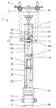
- FIG. 1 is a front view of a hydraulic shock absorber according to the present invention.
- FIG. 1 is drawn with a part of the cylinder broken.
- FIG. 2 is an enlarged cross-sectional view showing a connecting portion between the main piston rod and the vehicle body.
- FIG. 3 is an enlarged cross-sectional view showing a connection portion between the main piston rod and the sub piston rod.
- FIG. 4 is a cross-sectional view of the main piston rod for explaining the variable throttle.
- FIG. 5 is an enlarged cross-sectional view of the first support member.
- FIG. 6 is an enlarged cross-sectional view of the lid member and the wheel side connecting member.
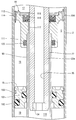
- FIG. 7 is an enlarged cross-sectional view of a part of the pipe, the second support member, and the free piston.
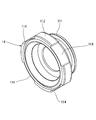
- FIG. 8 is a perspective view of the second support member.
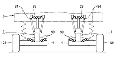
- FIG. 9A is a diagram for explaining the operation of the hydraulic shock absorber.
- FIG. 9A shows a state where the vehicle is stopped or traveling straight.
- FIG. 9B is a diagram for explaining the operation of the hydraulic shock absorber.
- FIG. 9B shows a state in which the wheel rides on a minute protrusion on the road.
- FIG. 9C is a diagram for explaining the operation of the hydraulic shock absorber.
- FIG. 9C shows a state during turning.
- FIG. 10 is a cross-sectional view showing another embodiment of the pipe.
- FIG. 11 is an enlarged cross-sectional view of a part of a pipe, a second support member, and a free piston according to another embodiment.
- FIG. 12 is a cross-sectional view showing another embodiment of the lid member.
- a hydraulic shock absorber 1 shown in FIG. 1 includes a cylinder 2 and a piston rod 3 projecting from one end portion (the upper end portion in FIG. 1) of the cylinder 2.
- the hydraulic shock absorber 1 according to this embodiment is used for a vehicle such as an automobile (not shown).
- a cylinder 2 shown in FIG. 1 is connected to a member (for example, a lower arm 4) that moves relative to a vehicle body together with a wheel in a vehicle suspension device via a wheel-side connecting member 5 described later.
- the piston rod 3 is connected to the vehicle body 6 of the vehicle via a vehicle body side connecting member 7 described later.
- the piston rod 3 is connected to a member (for example, the lower arm 4) that moves together with the wheels in the suspension device, and the cylinder 2 is connected to the vehicle body 6. It is also possible to take.
- the portion located on the upper side in FIG. 1 is referred to as the upper portion of the hydraulic shock absorber 1, and the portion located on the lower side in FIG. That's it.
- the cylinder 2 of the hydraulic shock absorber 1 is formed by a single cylinder.
- a first support member 11 is provided at the upper end portion (the end portion located on the upper side in FIG. 1) of the cylinder 2, and the lower end portion is closed by a lid member 12.
- a gas chamber 19 is formed.
- the first to third oil chambers 16 to 18 are filled with hydraulic oil.
- the gas chamber 19 is filled with a gas having a predetermined pressure. As this gas, for example, N 2 gas can be used.
- the piston rod 3 includes a main piston rod 21 slidably penetrating the first support member 11 and a sub piston rod 22 connected to a lower end portion of the main piston rod 21, that is, one end portion located in the cylinder 2. And is composed of.
- the sub piston rod 22 penetrates through a second support member 14 to be described later, and is slidably supported by the second support member 14.
- the outer diameter of the sliding portion 21a of the main piston rod 21 (the portion that slidably penetrates the first support member 11) is the same as the sliding portion 22a of the sub piston rod 22 (the second support member 14 is slidable). This is different from the outer diameter of the portion penetrating through the surface.
- the outer diameter of the sliding portion 22 a of the sub piston rod 22 is larger than the outer diameter of the sliding portion 21 a of the main piston rod 21.
- the sub piston rod 22 is positioned on the same axis as the main piston rod 21.
- a through hole 23 extending from one end of the main piston rod 21 to the other end is formed in the axial center portion of the main piston rod 21.
- a variable throttle 24 described later is provided in the through hole 23.
- the vehicle body side connecting member 7 is attached to the upper end portion of the main piston rod 21.
- the vehicle body side connection member 7 includes a disk-shaped connection plate 26 fixed to the upper end portion of the main piston rod 21 by a lock nut 25, a housing 27 surrounding the connection plate 26, and a buffer provided in the housing 27. Rubber 28.
- the housing 27 is fixed to the vehicle body 6 by fixing bolts 29.
- the buffer rubber 28 is injected and baked into the housing 27 in a state where the connecting plate 26 is located in the housing 27.
- the cushioning rubber 28 covers the outer peripheral portion of the connecting plate 26 from both sides in the vertical direction.
- a rubber member 30 is provided at the lower end of the housing 27. The rubber member 30 is sandwiched between the housing 27 and a cap 76 described later (see FIG. 5) when the hydraulic shock absorber 1 is greatly contracted, so as to alleviate the impact.
- a female screw 31 is formed in the upper end portion of the sub piston rod 22.
- a male screw 33 is formed at the lower end 32 of the main piston rod 21.
- the main piston rod 21 and the sub piston rod 22 are connected by screwing the female thread 31 of the sub piston rod 22 into the male thread 33 of the main piston rod 21.
- the female screw 31 is screwed into the male screw 33, first, the main piston rod 21 is gripped by a clamp device (not shown), and the rotation of the main piston rod 21 is restricted. Thereafter, the tool is engaged with a hexagonal hole 34 (see FIG. 7) formed in the lower end portion of the auxiliary piston rod 22. Then, the sub piston rod 22 is rotated using this tool, and the female screw 31 is screwed into the male screw 31.
- a non-through hole 35 is formed in the axial center portion of the auxiliary piston rod 22 according to this embodiment and between the vicinity of the female screw 31 and the hexagonal hole 34 in order to reduce the weight.
- the lower end portion 32 having the male thread 33 of the main piston rod 21 is formed to be thin with a step from the sliding portion 21 a of the main piston rod 21.
- An axial end face 36 is formed at the boundary portion between the lower end portion 32 of the main piston rod 21 and the sliding portion 21a of the main piston rod 21 and directed downward.
- the operation of connecting the main piston rod 21 and the sub piston rod 22 is performed in a state in which the piston 13 and a plate-like member around the piston described later are sandwiched between the axial end surface 36 and the sub piston rod 22. That is, the piston 13 is fixed between the main piston rod 21 and the sub piston rod 22.
- the piston 13 forms a first oil chamber 16 between the piston 13 and the first support member 11, and is connected to a later-described second support member 14 (see FIGS. 1 and 7) provided in the cylinder 2.
- a second oil chamber 17 is formed between them.
- the piston 13 according to this embodiment includes an annular piston body 41 and an annular bearing 42 and an O-ring 43 provided on the outer periphery of the piston body 41.
- the bearing 42 is for smooth sliding between the piston 13 and the cylinder 2.
- the O-ring 43 is for sealing between the inner peripheral surface of the bearing 42 and the piston 13.
- the piston body 41 is formed with a through hole 44 into which the lower end portion 32 of the main piston rod 21 is fitted and a plurality of oil holes to be described later.
- the through hole 44 is positioned in the axial center portion of the piston main body 41.
- the plurality of oil holes are an extension side oil hole 45 penetrating the left side of the piston 13 in the axial direction in FIG. 3, a compression side oil hole 46 penetrating the right side of the piston 13 in the axial direction in FIG.
- the communication hole 47 extends from the oil hole 46 toward the axial center of the piston 13.
- a plurality of the extension side oil holes 45 and the compression side oil holes 46 are alternately provided at appropriate intervals in the circumferential direction of the piston main body 41.
- extension-side oil hole 45 (the end on the first oil chamber 16 side) is connected to the first oil chamber 16 through a communication hole 48 formed in the piston main body 41.
- compression side oil hole 46 (the end on the second oil chamber 17 side) is connected to the second oil chamber 17 through a communication hole 49 formed in the piston main body 41.
- the extension side oil hole 45 and the communication hole 48, and the compression side oil hole 46 and the communication hole 49 constitute a “first hydraulic oil passage” according to the invention of claim 1. Has been.
- the communication hole 47 constitutes a part of a hydraulic oil passage that guides hydraulic oil to the variable throttle 24 described later.
- the communication hole 47 communicates the annular groove 50 formed in the through hole 44 of the piston body 41 and the compression side oil hole 46.
- the piston body 41 according to this embodiment has a plurality of plate-like shapes between the axial end surface 36 and the upper end surface of the sub piston rod 22 described above in a state where the lower end portion 32 of the main piston rod 21 is fitted in the through hole 44. It is sandwiched and fixed with the member.
- An annular plate 51, a plurality of shims 52, and a plurality of disk-shaped first leaf springs 53 are sandwiched between the piston 13 and the axial end face 36.
- a plurality of disc-shaped second leaf springs 54, a plurality of shims 55, and washers 56 are sandwiched between the piston 13 and the auxiliary piston rod 22.
- the plate 51 abuts against a later-described stopper rubber 83 (see FIG. 5) when the hydraulic shock absorber 1 is extended most.
- the first leaf spring 53 closes the opening on the first oil chamber 16 side in the extension side oil hole 45 and the compression side oil hole 46 formed in the piston 13.
- the second leaf spring 54 closes the opening on the second oil chamber 17 side in the extension side oil hole 45 and the compression side oil hole 46.
- the first leaf spring 53 and the second leaf spring 54 constitute the “throttle provided in the first hydraulic oil passage” according to the first aspect of the invention.
- the variable throttle 24 provided in the main piston rod 21 will be described.
- the variable throttle 24 includes a valve body 61 movably fitted in the through hole 23 of the main piston rod 21 and an operation body formed separately from the valve body 61.
- a rod 62 and a valve seat member 63 on which the valve body 61 is seated are provided.
- the valve body 61 includes a main body portion 61a formed in a conical shape whose tip is narrowed toward the valve seat member 63, and a columnar portion 61b formed integrally therewith.
- the operation rod 62 has a lower end abutting on the cylindrical portion 61b and extending from there to the vicinity of the upper end of the main piston rod 21, and an operation portion 62b provided at the upper end portion of the rod portion 62a. Yes.
- the cylindrical part 61b includes an O-ring 64 for sealing between the through hole 23 of the main piston rod 21.
- the cylindrical portion 61 b is fitted in the through hole 23 of the main piston rod 21.
- An oil chamber 65 in which the main body portion 61a is accommodated is formed below the cylindrical portion 61b in the through hole 23 and between the valve seat member 63 described later.
- the oil chamber 65 communicates with the first oil chamber 16 through an oil hole 66 formed in the main piston rod 21.
- the operation portion 62 b constitutes a screw with a hexagonal hole, and is screwed into a female screw 23 a formed on the hole wall surface of the upper end portion of the through hole 23. Further, the operation portion 62b is provided with a ball 67 for restricting the rotation of the operation rod 62. The ball 67 is pressed against the hexagonal hole 69 of the main piston rod 21 by a compression coil spring 68. By rotating the operation portion 62b and tightening the screw, the valve body 61 moves forward toward a valve seat member 63 described later. The pressure of the hydraulic oil acts on the valve body 61. This pressure is the pressure in the gas chamber 19 transmitted through the hydraulic oil by the pressure in the first oil chamber 16 and the second oil chamber 17.
- valve body 61 moves backward in a direction away from the valve seat member 63 by rotating the operation portion 62b to loosen the screw.
- the valve seat member 63 is formed in a bottomed cylindrical shape, and is fitted in the through hole 23 of the main piston rod 21 with the bottom portion positioned on the upper side (the valve body 61 side).
- An oil hole 70 into which the valve body 61 is inserted is formed at the bottom of the valve seat member 63.
- the open end (lower end) of the valve seat member 63 is pushed upward by the fixing bolt 71, and the bottom (upper end) of the valve seat member 63 is pressed against the step portion 23 b of the through hole 23 from below. .
- the fixing bolt 71 is screwed into a female screw 23 c formed at the lower end portion of the through hole 23 and closes the lower end of the through hole 23.
- the peripheral wall of the valve seat member 63 is formed with a plurality of oil holes 72 that allow the inside of the hollow portion of the valve seat member 63 to communicate with the outside of the valve seat member 63.
- These oil holes 72 are formed at positions corresponding to the annular groove 50 of the piston 13.
- the oil hole 72 and the annular groove 50 communicate with each other through an oil hole 73 formed in the main piston rod 21. That is, the first oil chamber 16 and the second oil chamber 17 of the hydraulic shock absorber 1 have a through hole 23 in the main piston rod 21 in addition to the extension side oil hole 45 and the compression side oil hole 46 of the piston 13.
- the hydraulic fluid passage 74 including the fluid throttle passage 24 is communicated with the variable throttle 24.
- the hydraulic oil passage 74 including the through hole 23 includes the communication hole 49 of the piston 13, the communication hole 47, the annular groove 50, the oil holes 66 and 73 of the main piston rod 21, and the oil hole of the valve seat member 63. 70, 72, a hollow portion, an oil chamber 65, and the like.
- the hydraulic oil passage 74 including the through hole 23 constitutes a “third hydraulic oil passage” as referred to in the inventions according to claims 5 to 7.
- the variable throttle 24 is fully closed when the valve body 61 is pressed against the opening edge of the oil hole 70 of the valve seat member 63.
- the variable throttle 24 functions as a throttle by forming a gap between the opening edge of the oil hole 70 of the valve seat member 63 and the valve body 61.
- the throttle amount can be adjusted by rotating the operating portion 62b to move the valve body 61 in the axial direction and changing the cross-sectional area of the gap described above.
- the variable throttle 24 can change the cross-sectional area of the “third hydraulic oil passage” in the inventions according to claims 5 to 7.
- the first support member 11 provided at one end of the cylinder 2 is formed in an annular shape as shown in FIG.
- the first support member 11 is supported by the cylinder 2 with the main piston rod 21 slidably passing through the hollow portion and the outer peripheral portion of the first support member 11 being fitted in the cylinder 2.
- the first support member 11 is fixed in a state in which it cannot move with respect to the cylinder 2 by a circlip 75 fixed to the inner peripheral portion of the cylinder 2 and a cap 76 that contacts the outer end surface of the cylinder 2.
- the cap 76 is attached to the first support member 11 by a plurality of fixing bolts 77.
- An O-ring 78 for sealing between the first support member 11 and the cylinder 2 is mounted on the outer periphery of the first support member 11.
- a plurality of members are attached to the inner peripheral portion of the first support member 11 in a state of being aligned in the axial direction. These plural members are a dust seal 79, a bearing 80, an oil seal 81, a washer 82, and a stopper rubber 83 in order from the top in FIG.
- the dust seal 79 is for preventing foreign matters such as dust and water from entering from the portion where the main piston rod 21 penetrates the first support member 11.
- the bearing 80 is press-fitted into the first support member 11 and slidably supports the main piston rod 21.
- the oil seal 81 is for preventing the hydraulic oil in the cylinder 2 (in the first oil chamber 16) from leaking outside through the penetrating portion of the main piston rod 21.
- the washer 82 is for supporting the stopper rubber 83.
- the stopper rubber 83 is for reducing the impact of the hydraulic shock absorber 1 when it is fully extended.
- the stopper rubber 83 contacts the plate 51 fixed to the main piston rod 21 when it is fully extended.
- a spring receiving member 84a (see FIG. 1) for supporting the coil spring 84 of the suspension device is attached to the upper portion of the cylinder 2 by a C ring 84b (see FIG. 3).
- the coil spring 84 is mounted in a compressed state between the vehicle body side and the spring receiving member 84a.
- the coil spring 84 of the suspension device may be provided independently of the hydraulic shock absorber 1.
- the lid member 12 that closes the lower end of the cylinder 2 is formed integrally with the bottomed cylindrical cylinder 85 fitted in the lower end of the cylinder 2 and the cylinder 85. And a pair of mounting plates 86 extending downward.
- a male screw 87 is formed at the upper end of the cylinder 85.
- an internal thread 88 is formed in the lower end portion of the cylinder 2.
- the lid member 12 is coupled to the cylinder 2 by the male screw 87 of the cylinder 85 being screwed into the female screw 88 of the cylinder 2.
- An O-ring 89 for sealing between the cylinder 2 is mounted on the outer peripheral portion of the cylindrical body 85 and below the male screw 87.
- a circular recess 91 that is fixed in a state in which a lower end portion of a pipe 90 described later is fitted is formed on the inner peripheral portion of the cylindrical body 85.
- the inner peripheral portion of the cylindrical body 85 is closed.
- an O-ring 92 for sealing between the pipe 90 is mounted on the inner peripheral portion of the cylinder 85.
- the lower end portion of the cylinder 85 is formed thicker than the lower end of the cylinder 2, and constitutes a stopper when the cylinder 85 is screwed into the cylinder 2. Further, a small hole 93 extending radially inward from the outer peripheral surface of the lid member 12, and a communication hole 94 communicating the inside of the distal end portion of the small hole 93 with the inside of the cylindrical body 85 are provided at the lower end portion of the cylindrical body 85. Is formed. A rubber plug member 95 is held at an intermediate portion in the small hole 93. A plug 96 is screwed into the opening of the small hole 93. The plug 96 is formed with a through hole 96a for piercing the plug member 95 through a gas injection needle (not shown).
- This needle is for injecting gas into the space (gas chamber 19) between the cylinder 85 and the pipe 90.
- the gas is injected into the small hole 93 from the tip of the needle penetrating the plug member 95.
- the needle is removed from the plug member 95 after gas injection. When the needle is removed from the plug member 95, the needle hole of the plug member 95 is closed and the small hole 93 is closed by the plug member 95.
- an on-off valve can be used in place of the plug member 95 in order to inject gas into the small hole 93.
- This on-off valve is a valve that opens when gas is supplied or when a gas supply device is connected, and closes when gas supply is stopped or when the gas supply device is removed. Can be used.
- This type of on-off valve is screwed into the opening on the atmosphere side of the small hole 93 in a state where the gas supply port or the supply device connecting portion protrudes from the lid member 12.
- a pair of attachment plates 86 provided at the lower end of the lid member 12 are for attaching the lower end of the hydraulic shock absorber 1 to a member (for example, the lower arm 4) that moves together with the wheel relative to the vehicle body in the suspension device.
- a mounting bracket 4 a provided on the lower arm 4 of the suspension device is mounted on the mounting plate 86 according to this embodiment via the wheel side connecting member 5.
- the wheel-side connecting member 5 includes an outer cylinder 97, an inner cylinder 98 inserted into the outer cylinder 97, and an annular cushioning rubber 99 disposed between the outer cylinder 97 and the inner cylinder 98. Has been.
- the buffer rubber 99 is baked on the outer cylinder 97 and the inner cylinder 98.
- the outer cylinder 97 is press-fitted into a mounting hole 4 b formed in the connecting bracket 4 a of the lower arm 4.
- the bracket 4a and the wheel side connecting member 5 are inserted between a pair of mounting plates 86, 86, and are fixed to the mounting plate 86 by bolts 100 inserted into the inner cylinder 98 in a state of passing through these members. .
- the pipe 90 fixed to the lid member 12 extends upward from the lid member 12 to the center of the cylinder 2 in the vertical direction.
- the pipe 90 is formed by a small-diameter portion 90 a that fits into the lid member 12 and a large-diameter portion 90 b that is positioned at the upper end portion, and is positioned on the same axis as the cylinder 2.
- the inner diameter of the small diameter portion 90 a of the pipe 90 is a size that can be inserted without contacting the lower end portion (tip portion) of the sub piston rod 22.
- the free piston 15 is slidably fitted to the small diameter portion 90a of the pipe 90.
- the free piston 15 is formed in an annular shape, and is slidably fitted to the pipe 90 and the cylinder 2 with the pipe 90 penetrating through the hollow portion.
- An O-ring 101 for sealing between the outer peripheral surface of the pipe 90 is attached to the inner peripheral portion of the free piston 15.
- An O-ring 102 and a bearing 103 are attached to the outer peripheral portion of the free piston 15 to seal the space between the inner peripheral surface of the cylinder 2.
- the free piston 15 partitions the third oil chamber 18 and the gas chamber 19 in the cylinder 2.
- the third oil chamber 18 is formed between the free piston 15 and a second support member 14 described later fixed to the large diameter portion of the pipe 90.
- the gas chamber 19 is formed between the free piston 15 and the lid member 12.
- the gas chamber 19 is filled with a gas having a pressure at which the free piston 15 is pressed toward the second support member 14. Gas filling is performed by inserting a needle for gas injection into a plug member 95 provided in the lid member 12.
- the large-diameter portion 90b of the pipe 90 is formed in a cylindrical shape by molding a base material (not shown) of the pipe 90 so that the outer diameter is larger than that of the small-diameter portion 90a.
- the outer diameter of the large diameter portion 90b is such that an annular space S is formed between the inner peripheral surface of the cylinder 2 as shown in FIG.
- the second support member 14 has a small diameter portion 111 and a large diameter portion 112, and an inner peripheral portion that slidably supports the sliding portion 22 a of the secondary piston rod 22. It is formed in the cylindrical shape which has.
- the small diameter portion 111 of the second support member 14 is fitted into the large diameter portion 90b of the pipe 90 described above, and is fixed by press-fitting.
- An O-ring 113 for sealing between the small diameter portion 111 and the inner peripheral surface of the pipe 90 is attached.
- the large-diameter portion 112 of the second support member 14 (the outer peripheral portion of the second support member 14) is fitted into the cylinder 2 with a clearance fit, and the second oil chamber 17 in the cylinder 2 and the third oil chamber 17
- the oil chamber 18 is partitioned.
- the second oil chamber 17 is formed between the piston 13 and the second support member 14.
- the third oil chamber 18 is formed between the second support member 14 and the free piston 15.
- a plurality of notches 114 extending in the axial direction of the second support member 14 are formed in the large diameter portion 112. These notches 114 communicate the second oil chamber 17 and the third oil chamber 18.
- the notch 114 is formed in the large diameter portion 112 of the second support member 14 in a shape in which the distance from the inner peripheral surface of the cylinder 2 is partially increased.
- these notches 114 are arranged at regular intervals in the circumferential direction of the large diameter portion 112.
- the total cross-sectional area of these plurality of notches 114 (the cross-sectional area viewed from the axial direction of the second support member 14) is a size that allows hydraulic oil to pass freely.
- This total cross-sectional area is not less than the difference between the cross-sectional area of the sliding portion 21 a of the main piston rod 21 and the cross-sectional area of the sliding portion 22 a of the sub-piston rod 22. For this reason, hydraulic fluid can freely pass through the notch 114 as necessary.
- the plurality of cutouts 114 constitute a “second hydraulic oil passage” in the present invention.
- a washer 115, an oil seal 116, and a bearing 117 are provided in order from the top on the inner peripheral portion of the second support member 14.
- the washer 115 is for preventing the oil seal 116 from coming off from the second support member 14, and is fixed in the large diameter portion 112 by caulking the end face of the large diameter portion 112.
- the oil seal 116 seals between the second support member 14 and the outer peripheral surface of the sub piston rod 22.
- the bearing 117 slidably supports the sub piston rod 22.
- the hollow portion of the second support member 14 is closed by the secondary piston rod 22.
- the large diameter portion 90 b of the pipe 90 is closed by the small diameter portion 111 of the second support member 14 and the auxiliary piston rod 22. That is, in the hydraulic shock absorber 1, the inside of the pipe 90 becomes the sealed space 118, so that dust does not enter the pipe 90 from the outside.
- the outer diameter of the sliding portion 22a of the secondary piston rod 22 is larger than the outer diameter of the sliding portion 21a of the main piston rod 21.
- the hydraulic oil passes from the second oil chamber 17 through the notch 114 of the second support member 14 and flows into the third oil chamber 18 as indicated by solid arrows in FIG.
- the total cross-sectional area of the notch 114 is not less than the difference between the cross-sectional area of the sliding portion 21 a of the main piston rod 21 and the cross-sectional area of the sliding portion 22 a of the sub piston rod 22. For this reason, since the hydraulic oil smoothly flows in the notch 114 as the piston 13 moves, cavitation does not occur in the oil chamber even when the moving speed of the piston 13 is high.
- the hydraulic oil flows from the third oil chamber 18 through the notch 114 of the second support member 14 and flows into the second oil chamber 17.
- the direction in which the hydraulic oil flows at this time is a direction indicated by a dashed arrow in FIG. At this time, cavitation does not occur in the oil chamber.
- the hydraulic oil in the hydraulic shock absorber 1 is pressurized with the gas pressure in the gas chamber 19. For this reason, the gas reaction force having a magnitude corresponding to the difference between the pressure receiving area on the first oil chamber 16 side and the pressure receiving area on the second oil chamber 17 side acts on the piston 13 even in a natural state. .
- the pressure receiving area on the first oil chamber 16 side is larger than the pressure receiving area on the second oil chamber 17 side.
- the piston 13 is pushed toward the second support member 14 by the gas reaction force. That is, the hydraulic shock absorber 1 contracts in a natural state.
- the piston 13 is pushed and moved by the gas reaction force described above until the washer 56 provided near the lower side of the piston 13 contacts the washer 115 on the second support member 14 side.
- the spring receiving member 84a is attached to the cylinder 2 of the hydraulic shock absorber 1 by the C ring 84b.
- the main piston rod 21 is held in a state protruding a predetermined amount from the cylinder 2.
- a dedicated jig (not shown) is used, or gas is supplied to the sealed space 118 in the pipe 90.
- the coil spring 84 of the suspension device is attached to the spring receiving member 84a, and the vehicle body side connecting member 7 is attached to the main piston rod 21.
- the vehicle body side connecting member 7 positioned at the upper end of the assembly is attached to the vehicle body 6, and the lid member 12 positioned at the lower end of the assembly is attached to the lower arm 4 by the wheel side connecting member 5.
- the holding of the main piston rod 21 is released. The release of the holding is performed by removing the jig holding the main piston rod 21 or discharging the gas from the sealed space 118.
- the hydraulic shock absorber 1 to the suspension device, the vehicle weight is applied as a load to the shock absorbing rubber 99 of the wheel side connecting member 5. In the cushioning rubber 99, the portion located above the inner cylinder 98 in FIG. 6 is pulled, and the portion located below the inner cylinder 98 is compressed.
- the hydraulic shock absorber 1 contracts in a natural state. For this reason, when the hydraulic shock absorber 1 is attached to the suspension device, an initial set load is applied to the shock absorbing rubber 28 of the vehicle body side connecting member 7, and an initial deformation occurs. In the shock absorbing rubber 28 of the vehicle body side connecting member 7, a portion located below the connecting plate 26 in FIG. 2 is compressed, and a portion located above the connecting plate 26 is pulled.
- FIGS. 9A to 9C the operation of the hydraulic shock absorber 1 mounted on the vehicle will be described with reference to FIGS. 9A to 9C. 9A to 9C are drawn with the vehicle viewed from the rear.
- 9A to 9C schematically show the hydraulic shock absorber 1 on the left side of the vehicle body, the hydraulic shock absorber 1 on the right side of the vehicle body, and the cushioning rubbers 28 and 99 connected to these hydraulic shock absorbers 1. is there. 9A to 9C are drawn with the wheels 121 connected to the lower arm 4. Further, in FIG. 9A to FIG. 9C, the coil spring 84 of the suspension device provided independently of the hydraulic shock absorber 1 is drawn by a two-dot chain line.
- the buffer rubber 28 When the vehicle is stopped or traveling straight on a flat road surface, the buffer rubber 28 is deformed by being pulled toward the hydraulic shock absorber 1 by the gas reaction force as shown in FIG. 9A. Hereinafter, this deformation is simply referred to as initial deformation.
- the buffer rubber 99 is deformed by the vehicle weight and is bent downward.
- the cushioning rubber 28 When the vehicle travels in this state and the left wheel 121 rides on the minute convex portion 122 on the road, for example, a white line, as shown in FIG. 9B, the cushioning rubber 28 is deformed by the initial deformation, and the hydraulic cylinder Since 1 is displaced upward, the initial deformation of the buffer rubber 28 is partially or completely eliminated. In this case, the hydraulic shock absorber 1 is not in operation (shrinkage), and the shock transmitted from the wheel 121 to the vehicle body 6 side is alleviated by the shock absorbing rubber 28.
- the buffer rubber 99 is initially deformed into a shape that protrudes upward as indicated by a two-dot chain line in FIG. 9A due to the gas reaction force. It is bent by. For this reason, when the left wheel rides on the convex portion 122 such as a white line, the initial deformation of the cushioning rubber 99 is partially or entirely eliminated as shown by a two-dot chain line in FIG. 9B. That is, in this case, the impact transmitted from the wheel 121 to the vehicle body 6 side is mitigated by both the cushioning rubber 28 and the cushioning rubber 99.
- the hydraulic shock absorber 1 on the right side of the vehicle body contracts and the hydraulic shock absorber 1 on the left side of the vehicle body extends to generate a damping force.
- the hydraulic shock absorber 1 located on the right side of the vehicle body when the vehicle body 6 is slightly lowered, the initial deformation is eliminated in the shock absorbing rubber 28, and the damping force is applied immediately after the deformation bending in the reverse direction is completed as shown in FIG. 9C. appear.
- the coil spring 84 is provided independently of the hydraulic shock absorber 1, the initial deformation is eliminated in the shock absorbing rubber 28 and the shock absorbing rubber 99.
- the hydraulic shock absorber 1 when the piston 13 moves relative to the cylinder 2, the cross-sectional area of the sliding portion 21a of the main piston rod 21 and the cross-sectional area of the sliding portion 22a of the sub-piston rod 22
- the hydraulic oil flows through the notch 114 of the second support member 14 by a flow rate corresponding to the difference between the two.
- the total cross-sectional area of the notch 114 is not less than the difference between the cross-sectional area of the sliding portion 21 a of the main piston rod 21 and the cross-sectional area of the sliding portion 22 a of the sub piston rod 22. For this reason, since the hydraulic oil flows smoothly through the notch 114 as the piston 13 moves, cavitation does not occur in the oil chamber even when the moving speed of the piston 13 is high.
- the operability of the piston rod 3 is enhanced, and an initial set load can be applied to the shock absorbing rubber 28 of the vehicle while preventing cavitation in the oil chamber.
- an initial set load can be applied to both the shock absorbing rubber 28 and the shock absorbing rubber 99.
- a hydraulic shock absorber can be provided.
- the notch 114 (second hydraulic oil passage) of the second support member 14 is partially spaced from the outer peripheral portion of the second support member 14 with the inner peripheral surface of the cylinder 2. It is formed into a shape.
- the notch 114 is formed using a wide range excluding a portion (a portion for accommodating the oil seal 116 and the bearing 117) necessary for supporting the sub piston rod 22 in the second support member 14. For this reason, there are few restrictions in forming this notch 114, and the notch 114 can easily form a hydraulic oil passage (second hydraulic oil passage) having a large cross-sectional area. Therefore, according to this embodiment, it is possible to provide a hydraulic shock absorber that is less susceptible to cavitation.
- the outer diameter of the sliding portion 22 a of the sub piston rod 22 according to this embodiment is larger than the outer diameter of the sliding portion 21 a of the main piston rod 21.
- the pressure receiving area on the second oil chamber 17 side of the piston 13 is smaller than the pressure receiving area on the first oil chamber 16 side.
- the piston 13 receives a gas reaction force having a magnitude corresponding to the difference in pressure receiving area, and moves toward the second support member 14 by the gas reaction force.
- the hydraulic shock absorber 1 according to this embodiment contracts in a natural state as described above.
- the shock absorbing rubber 28 of the suspension device is pulled by the hydraulic shock absorber 1, and an initial set load (load that causes initial deformation) is applied to the shock absorbing rubber 28. Is granted.
- an initial set load is applied to both the shock absorbing rubber 28 and the shock absorbing rubber 99.
- the initial deformation of the shock absorbing rubber 28 is partially or completely eliminated, so that the shock is transmitted to the vehicle body 6 even when the hydraulic shock absorber 1 is not activated. It becomes difficult to be done and ride comfort improves.
- the hydraulic shock absorber 1 includes a hydraulic oil passage 74 (third hydraulic oil passage) that communicates between the first oil chamber 16 and the second oil chamber 17 through the main piston rod 21. ing.
- the hydraulic shock absorber 1 includes a variable throttle 24 that can change the cross-sectional area of the hydraulic oil passage 74. Therefore, the magnitude of the damping force generated in the hydraulic shock absorber 1 can be changed by changing the cross-sectional area of the hydraulic oil passage 74 by the variable throttle 24. Therefore, according to this embodiment, since the magnitude of the damping force can be adjusted according to the model of the vehicle to which the hydraulic shock absorber 1 is attached and the preference of the occupant, the hydraulic shock absorber that further improves riding comfort is provided. Can be provided.
- the pipe 90 includes a small-diameter portion 90a into which the free piston 15 is slidably fitted, and a large-diameter portion where the outer diameter is formed larger than the small-diameter portion 90a and the second support member 14 is fixed. 90b.
- the second support member 14 is fixed in a state of being fitted into the large diameter portion 90 b of the pipe 90.
- the area of the contact portion between the second support member 14 and the pipe 90 is the contact portion when the second support member 14 is fitted to the small diameter portion 90 a of the pipe 90. Larger than the area.
- the sub piston rod is not affected by the magnitude of the hydraulic pressure acting on the second support member 14. 22 is supported in a stable state. That is, the piston rod 3 operates smoothly. Therefore, according to this embodiment, since the operation of the hydraulic shock absorber 1 when it is extended or contracted is smooth and does not give a sense of incongruity to the occupant, it is possible to provide a hydraulic shock absorber that improves riding comfort. .
- the pipe and the second support member can be formed as shown in FIGS.
- members that are the same as or equivalent to those described with reference to FIGS. 1 to 9C are denoted by the same reference numerals, and detailed description thereof is omitted as appropriate.
- the pipe 90 shown in FIGS. 10 and 11 is formed in a shape having a constant outer diameter from one end to the other end.
- the small diameter portion 111 of the second support member 14 is formed longer in the axial direction than in the case of adopting the first embodiment.
- the second support member 14 according to this embodiment is fixed to the pipe 90 in a state where the pipe 90 is fitted in the small diameter portion 111.
- the pipe 90 is press-fitted into the small diameter part 111.
- the small-diameter portion 111 is provided with an O-ring 123 for sealing between the outer peripheral surface of the pipe 90.
- the pipe 90 having a constant outer diameter in this way can be used with a low price due to mass production. Therefore, according to this embodiment, it is possible to provide a hydraulic shock absorber that not only improves ride comfort when mounted on a vehicle, but also reduces manufacturing costs.
- the lid member can be formed as shown in FIG. 12, members identical or equivalent to those described with reference to FIGS. 1 to 11 are given the same reference numerals, and detailed description thereof will be omitted as appropriate.
- gas supply passage 131 that communicates the inside of the circular recess 91 and the outside of the lid member 12.
- One end of the gas supply passage 131 opens to the inner peripheral surface of the circular recess 91.
- the gas supply passage 131 extends in the radial direction of the lid member 12 from this one end.
- the other end of the gas supply passage 131 is open to the outer peripheral surface of the lid member 12. That is, the gas supply passage 131 is connected to the sealed space 118 in the pipe 90 via the circular recess 91.
- a rubber plug member 132 is held in the middle of the gas supply passage 131.
- a plug 133 is screwed into the opening of the gas supply passage 131.
- the plug 133 is formed with a through-hole 135 for piercing the plug member 132 through a gas injection needle 134.
- the needle 134 is for injecting gas into the sealed space 118 in the pipe 90. The gas is discharged into the gas supply passage 131 from the distal end portion of the needle 134 that penetrates the plug member 132.
- the gas supplied to the gas supply passage 131 cancels out the gas reaction force caused by the difference between the sectional area of the sliding portion 21a of the main piston rod 21 and the sectional area of the sliding portion 22a of the sub piston rod 22.
- Pressure or higher pressure gas By supplying the gas to the gas supply passage 131 using the needle 134, the pressure in the gas supply passage 131 and the sealed space 118 is increased.
- the pressure in the gas supply passage 131 and the sealed space 118 is reduced.
- the needle 134 is removed from the plug member 132, the needle hole of the plug member 132 is closed with elasticity, and the gas supply passage 131 and the sealed space 118 are closed in a predetermined low pressure state.
- the “low pressure state” here refers to a state of atmospheric pressure or a pressure slightly higher than atmospheric pressure.
- the sealed space 118 in the pipe 90 can be switched between the form in which the gas is supplied and the pressure is increased, and the form in which the gas is extracted and closed in a predetermined low pressure state.
- a gas supply passage 131 is connected. When gas is supplied from the gas supply passage 131 to the sealed space 118, gas pressure acts on the sub piston rod 22, and the main piston rod 21 moves in a direction protruding from the cylinder 2 together with the sub piston rod 22. .
- the overall length of the hydraulic shock absorber 1 can be adjusted according to the mounting position of the suspension device. Therefore, according to this embodiment, it is possible to provide a hydraulic shock absorber that can be easily assembled to the suspension device.
- a rubber plug member 132 is used to close the gas supply passage 131.
- an on-off valve can be used.
- This on-off valve is a valve that opens when gas is supplied or when a gas supply device is connected, and closes when gas supply is stopped or when the gas supply device is removed. Can be used. Examples of such on-off valves include English valves (English ⁇ Valve), American valves (French Valve), and French valves (French Valve) widely used for bicycle and automobile tires.
- This type of on-off valve is screwed into the atmosphere-side opening of the gas supply passage 131 in a state where the gas supply port or the supply device connecting portion protrudes from the lid member 12.
- the outer diameter of the sliding portion 22a of the sub piston rod 22 is larger than the outer diameter of the sliding portion 21a of the main piston rod 21.
- the hydraulic shock absorber 1 according to the present invention can take a form in which the outer diameter of the sliding portion 21 a of the main piston rod 21 is larger than the outer diameter of the sliding portion 22 a of the sub piston rod 22.
- the hydraulic shock absorber 1 adopting this configuration extends in a natural state, and applies an initial set load (a load that causes initial deformation) to the shock absorbing rubber in a state where the hydraulic shock absorber 1 is assembled to a vehicle suspension device. For this reason, even when this configuration is adopted, the same effect as that obtained when the first embodiment is adopted can be obtained.
Landscapes
- Engineering & Computer Science (AREA)
- Mechanical Engineering (AREA)
- General Engineering & Computer Science (AREA)
- Fluid-Damping Devices (AREA)
- Vehicle Body Suspensions (AREA)
Abstract
Priority Applications (4)
| Application Number | Priority Date | Filing Date | Title |
|---|---|---|---|
| US15/024,403 US9751371B2 (en) | 2013-09-25 | 2014-07-09 | Hydraulic shock absorber |
| CA2925253A CA2925253C (fr) | 2013-09-25 | 2014-07-09 | Amortisseur hydraulique |
| EP14848725.9A EP3051174B1 (fr) | 2013-09-25 | 2014-07-09 | Amortisseur hydraulique |
| JP2015538971A JP5997392B2 (ja) | 2013-09-25 | 2014-07-09 | 油圧緩衝器 |
Applications Claiming Priority (2)
| Application Number | Priority Date | Filing Date | Title |
|---|---|---|---|
| JP2013-198036 | 2013-09-25 | ||
| JP2013198036 | 2013-09-25 |
Publications (1)
| Publication Number | Publication Date |
|---|---|
| WO2015045558A1 true WO2015045558A1 (fr) | 2015-04-02 |
Family
ID=52742716
Family Applications (1)
| Application Number | Title | Priority Date | Filing Date |
|---|---|---|---|
| PCT/JP2014/068280 Ceased WO2015045558A1 (fr) | 2013-09-25 | 2014-07-09 | Amortisseur hydraulique |
Country Status (5)
| Country | Link |
|---|---|
| US (1) | US9751371B2 (fr) |
| EP (1) | EP3051174B1 (fr) |
| JP (1) | JP5997392B2 (fr) |
| CA (1) | CA2925253C (fr) |
| WO (1) | WO2015045558A1 (fr) |
Families Citing this family (5)
| Publication number | Priority date | Publication date | Assignee | Title |
|---|---|---|---|---|
| US11199236B2 (en) | 2017-11-27 | 2021-12-14 | Yamaha Hatsudoki Kabushiki Kaisha | Suspension device |
| CN109737176B (zh) * | 2019-01-15 | 2025-01-17 | 四川川南减震器集团有限公司 | 165mm电动自行车液压减震器 |
| CN112460182A (zh) * | 2020-12-12 | 2021-03-09 | 金鹰重型工程机械股份有限公司 | 一种带支撑功能的液压减振器 |
| DE102021100226B4 (de) * | 2021-01-08 | 2024-08-08 | Vibracoustic Se | Dämpfer für eine Luftfeder |
| CN116856984A (zh) * | 2022-02-23 | 2023-10-10 | 杨柯 | 一种可延伸液压支架 |
Citations (3)
| Publication number | Priority date | Publication date | Assignee | Title |
|---|---|---|---|---|
| JPS5950808A (ja) * | 1982-09-14 | 1984-03-24 | Isuzu Motors Ltd | 車両の懸架装置 |
| JP4996957B2 (ja) | 2007-03-29 | 2012-08-08 | カヤバ工業株式会社 | 緩衝器および緩衝器の組立工具 |
| JP2013181586A (ja) * | 2012-02-29 | 2013-09-12 | Showa Corp | 油圧緩衝装置およびフリーピストン |
Family Cites Families (8)
| Publication number | Priority date | Publication date | Assignee | Title |
|---|---|---|---|---|
| JPS516605Y2 (fr) | 1971-07-22 | 1976-02-23 | ||
| EP1944523B1 (fr) * | 2005-10-31 | 2019-01-23 | Yamaha Hatsudoki Kabushiki Kaisha | Amortisseur |
| KR20080042324A (ko) * | 2006-11-09 | 2008-05-15 | 주식회사 만도 | 모노 튜브식 쇽업소버 |
| JP4753903B2 (ja) * | 2007-03-12 | 2011-08-24 | ヤマハ発動機株式会社 | 油圧緩衝器 |
| JP5014963B2 (ja) * | 2007-11-26 | 2012-08-29 | カヤバ工業株式会社 | 緩衝器 |
| JP2010096347A (ja) * | 2008-09-22 | 2010-04-30 | Yamaha Motor Co Ltd | 油圧緩衝器 |
| JP5403755B2 (ja) * | 2010-02-15 | 2014-01-29 | カヤバ工業株式会社 | 緩衝器 |
| JP5809536B2 (ja) * | 2011-11-15 | 2015-11-11 | カヤバ工業株式会社 | 車両用緩衝器 |
-
2014
- 2014-07-09 US US15/024,403 patent/US9751371B2/en active Active
- 2014-07-09 EP EP14848725.9A patent/EP3051174B1/fr active Active
- 2014-07-09 CA CA2925253A patent/CA2925253C/fr active Active
- 2014-07-09 JP JP2015538971A patent/JP5997392B2/ja active Active
- 2014-07-09 WO PCT/JP2014/068280 patent/WO2015045558A1/fr not_active Ceased
Patent Citations (3)
| Publication number | Priority date | Publication date | Assignee | Title |
|---|---|---|---|---|
| JPS5950808A (ja) * | 1982-09-14 | 1984-03-24 | Isuzu Motors Ltd | 車両の懸架装置 |
| JP4996957B2 (ja) | 2007-03-29 | 2012-08-08 | カヤバ工業株式会社 | 緩衝器および緩衝器の組立工具 |
| JP2013181586A (ja) * | 2012-02-29 | 2013-09-12 | Showa Corp | 油圧緩衝装置およびフリーピストン |
Non-Patent Citations (1)
| Title |
|---|
| See also references of EP3051174A4 |
Also Published As
| Publication number | Publication date |
|---|---|
| US20160243913A1 (en) | 2016-08-25 |
| EP3051174A4 (fr) | 2017-06-14 |
| CA2925253C (fr) | 2017-08-22 |
| JPWO2015045558A1 (ja) | 2017-03-09 |
| US9751371B2 (en) | 2017-09-05 |
| CA2925253A1 (fr) | 2015-04-02 |
| JP5997392B2 (ja) | 2016-09-28 |
| EP3051174A1 (fr) | 2016-08-03 |
| EP3051174B1 (fr) | 2022-05-11 |
Similar Documents
| Publication | Publication Date | Title |
|---|---|---|
| US8251355B2 (en) | Front fork | |
| US20180216690A1 (en) | Shock absorber | |
| JP5997392B2 (ja) | 油圧緩衝器 | |
| JPWO2019239720A1 (ja) | 減衰力発生機構および圧力緩衝装置 | |
| WO2019230550A1 (fr) | Appareil de suspension | |
| KR20110098616A (ko) | 완충기 | |
| WO2014155809A1 (fr) | Dispositif d'amortissement de pression | |
| CN100412406C (zh) | 减振器的相邻导流板设计 | |
| US10533623B2 (en) | Front fork | |
| US6899207B2 (en) | Extra support area for valve disc | |
| JP6046106B2 (ja) | ストロークの初期における減衰が弱められた2つのピストンを備えた緩衝装置 | |
| CN111108302A (zh) | 前叉及前叉的制造方法 | |
| JP2016098895A (ja) | 圧力緩衝装置 | |
| US20160046349A1 (en) | Hydraulic shock absorber and method for injecting operating liquid into hydraulic shock absorber | |
| JP2009156348A (ja) | 油圧緩衝器 | |
| WO2022044560A1 (fr) | Amortisseur | |
| JP2008240918A (ja) | 減衰力発生装置 | |
| JP2016194338A (ja) | 油圧緩衝器 | |
| JP6546453B2 (ja) | 減衰バルブおよび緩衝器 | |
| JP7482204B1 (ja) | 緩衝器 | |
| JP2016080140A (ja) | 圧力緩衝装置 | |
| JP6403590B2 (ja) | 圧力緩衝装置 | |
| WO2019082610A1 (fr) | Fourche avant | |
| WO2018163523A1 (fr) | Amortisseur pour véhicule | |
| JP4740045B2 (ja) | 油圧緩衝器の減衰バルブ |
Legal Events
| Date | Code | Title | Description |
|---|---|---|---|
| 121 | Ep: the epo has been informed by wipo that ep was designated in this application |
Ref document number: 14848725 Country of ref document: EP Kind code of ref document: A1 |
|
| ENP | Entry into the national phase |
Ref document number: 2015538971 Country of ref document: JP Kind code of ref document: A |
|
| ENP | Entry into the national phase |
Ref document number: 2925253 Country of ref document: CA |
|
| REEP | Request for entry into the european phase |
Ref document number: 2014848725 Country of ref document: EP |
|
| WWE | Wipo information: entry into national phase |
Ref document number: 15024403 Country of ref document: US Ref document number: 2014848725 Country of ref document: EP |
|
| NENP | Non-entry into the national phase |
Ref country code: DE |