WO2015053104A1 - インクジェット印刷方法 - Google Patents
インクジェット印刷方法 Download PDFInfo
- Publication number
- WO2015053104A1 WO2015053104A1 PCT/JP2014/075780 JP2014075780W WO2015053104A1 WO 2015053104 A1 WO2015053104 A1 WO 2015053104A1 JP 2014075780 W JP2014075780 W JP 2014075780W WO 2015053104 A1 WO2015053104 A1 WO 2015053104A1
- Authority
- WO
- WIPO (PCT)
- Prior art keywords
- ink
- ink layer
- layer
- drying
- forming step
- Prior art date
- Legal status (The legal status is an assumption and is not a legal conclusion. Google has not performed a legal analysis and makes no representation as to the accuracy of the status listed.)
- Ceased
Links
Images


Classifications
-
- B—PERFORMING OPERATIONS; TRANSPORTING
- B41—PRINTING; LINING MACHINES; TYPEWRITERS; STAMPS
- B41J—TYPEWRITERS; SELECTIVE PRINTING MECHANISMS, i.e. MECHANISMS PRINTING OTHERWISE THAN FROM A FORME; CORRECTION OF TYPOGRAPHICAL ERRORS
- B41J11/00—Devices or arrangements of selective printing mechanisms, e.g. ink-jet printers or thermal printers, for supporting or handling copy material in sheet or web form
- B41J11/0015—Devices or arrangements of selective printing mechanisms, e.g. ink-jet printers or thermal printers, for supporting or handling copy material in sheet or web form for treating before, during or after printing or for uniform coating or laminating the copy material before or after printing
- B41J11/002—Curing or drying the ink on the copy materials, e.g. by heating or irradiating
- B41J11/0021—Curing or drying the ink on the copy materials, e.g. by heating or irradiating using irradiation
- B41J11/00214—Curing or drying the ink on the copy materials, e.g. by heating or irradiating using irradiation using UV radiation
-
- B—PERFORMING OPERATIONS; TRANSPORTING
- B41—PRINTING; LINING MACHINES; TYPEWRITERS; STAMPS
- B41J—TYPEWRITERS; SELECTIVE PRINTING MECHANISMS, i.e. MECHANISMS PRINTING OTHERWISE THAN FROM A FORME; CORRECTION OF TYPOGRAPHICAL ERRORS
- B41J2/00—Typewriters or selective printing mechanisms characterised by the printing or marking process for which they are designed
- B41J2/005—Typewriters or selective printing mechanisms characterised by the printing or marking process for which they are designed characterised by bringing liquid or particles selectively into contact with a printing material
- B41J2/01—Ink jet
-
- B—PERFORMING OPERATIONS; TRANSPORTING
- B41—PRINTING; LINING MACHINES; TYPEWRITERS; STAMPS
- B41M—PRINTING, DUPLICATING, MARKING, OR COPYING PROCESSES; COLOUR PRINTING
- B41M3/00—Printing processes to produce particular kinds of printed work, e.g. patterns
- B41M3/008—Sequential or multiple printing, e.g. on previously printed background; Mirror printing; Recto-verso printing; using a combination of different printing techniques; Printing of patterns visible in reflection and by transparency; by superposing printed artifacts
-
- B—PERFORMING OPERATIONS; TRANSPORTING
- B41—PRINTING; LINING MACHINES; TYPEWRITERS; STAMPS
- B41M—PRINTING, DUPLICATING, MARKING, OR COPYING PROCESSES; COLOUR PRINTING
- B41M7/00—After-treatment of prints, e.g. heating, irradiating, setting of the ink, protection of the printed stock
- B41M7/0081—After-treatment of prints, e.g. heating, irradiating, setting of the ink, protection of the printed stock using electromagnetic radiation or waves, e.g. ultraviolet radiation, electron beams
Definitions
- the present invention relates to an inkjet printing method.
- the ink layer is cured by irradiating the ink layer formed by ejecting the ultraviolet curable ink onto the recording medium.
- an inkjet printing method using such an ultraviolet curable ink for example, a printing method described in Patent Document 1 is known.
- the ultraviolet curable ink includes a transparent ultraviolet curable ink containing no colorant, and is known as a clear ink.
- the clear ink is used as an overcoat on a color print, a coating on a recording medium, or the like.
- the ultraviolet curable ink is ejected to the printing medium by the ink jet printing method described in Patent Document 1, the surface of the ink layer immediately after landing on the recording medium has irregularities.
- clear ink is used as an overcoat or the like, gloss unevenness may occur in a printed matter due to a difference in reflectance due to the unevenness.
- the present invention has been made in view of the above circumstances, and an object of the present invention is to provide an ink jet printing method capable of obtaining a highly glossy print without bleeding.
- an ink jet printing method includes a second ink layer formed on a first ink layer formed on a recording medium by discharging a second ink and then drying the second ink layer.
- the drying time is shorter than the drying time in the third ink layer forming step.
- the second ink in the second ink layer forming step of forming the second ink layer in contact with the first ink layer, the second ink causes the ink in the first ink layer to be dried by the second ink in a short time. It can prevent bleeding quickly. Moreover, since the third ink layer is further provided on the second ink layer and the third ink is dried over a long time, the surface of the third ink layer can be sufficiently flattened. Thereby, it is possible to obtain a highly glossy print without bleeding.
- the first ink forming the first ink layer is a solvent-soluble ink.
- the second ink is formed at the time of forming the second ink layer in contact with the first ink layer. Since the drying time for drying is short, it is possible to obtain a highly glossy print without bleeding.
- the second ink and the third ink are the same.
- the second ink layer prevents the first ink layer from bleeding by simply using the same ink and making the drying time of the second ink layer shorter than the drying time of the third ink layer. Since the gloss of the printed material can be obtained by the ink layer, it is possible to easily obtain a highly glossy printed material without bleeding.
- the third ink is preferably a clear ink.
- the surface of the third ink layer can be sufficiently flattened to obtain high glossiness, a high gloss overcoat is possible by using clear ink as the third ink layer. is there.
- the second ink is preferably an ultraviolet curable ink.
- the second ink layer is formed of the ultraviolet curable ink excellent in quick-drying property, it is possible to obtain a printed matter with less bleeding.
- the drying time in the second ink layer forming step for forming the second ink layer on the first ink layer is the third ink layer for forming the third ink layer on the second ink layer. Since it is shorter than the drying time in the forming step, it is possible to prevent the ink of the first ink layer from dissolving and bleeding, and to obtain a printed matter excellent in glossiness coated with the third ink layer.
- FIG. 1 is a schematic diagram illustrating an ink jet printing method according to an embodiment of the present invention.
- the ink jet printing method according to an embodiment of the present invention includes a second ink layer forming step of discharging a second ink onto the first ink layer 1 formed on the recording medium 10 and then drying the second ink layer, and the second ink.
- a third ink layer forming step of discharging the third ink on the layer 2 and then drying it is included.
- the drying time in the second ink layer forming step is shorter than the drying time in the third ink layer forming step.
- the second ink is dried over a shorter time than the drying time in the third ink layer forming step, and the third ink is dried over a longer time than the drying time in the second ink layer forming step.
- the second ink layer is dried in a shorter time than the third ink layer.
- the ink jet printing method according to the present invention may further include a first ink layer forming step of forming the first ink layer 1 on the recording medium 10 as shown in FIG.
- the first ink layer forming step the first ink for forming the first ink layer 1 is discharged onto the recording medium 10 and dried.
- the ejection of the first ink to the recording medium 10 can be suitably performed using a conventionally known ink jet printing apparatus.
- the recording medium 10 a conventionally known recording medium or the like can be suitably used.
- the first ink for forming the first ink layer various conventionally known inks such as ultraviolet curable ink, solvent ink, and latex ink can be used, and even color inks containing a colorant can be used. Good.
- the first ink is preferably an ultraviolet curable ink having excellent quick drying properties.
- the first ink layer forming step After the first ink is ejected onto the recording medium 10, the first ink layer 1 is irradiated by irradiating ultraviolet rays from an LED or the like. Can be cured. Thereby, the first ink layer 1 can be formed in a shorter time.
- the first ink may be a solvent-soluble ink.
- the ink soluble in the solvent include LUS-150, LF-140, LF-200, and LUS-200 manufactured by Mimaki Engineering. Even if the first ink layer 1 is formed using the first ink that is more easily bleed and soluble in the solvent, as described later, the second ink is applied when the second ink layer 2 in contact with the first ink layer is formed. Since the drying time for drying is short, it is possible to obtain a highly glossy print without bleeding.
- the second ink layer is ejected onto the first ink layer 1 formed on the recording medium 10 and then dried to form the second ink layer. 2 is formed. And the drying time in a 2nd ink layer formation process is shorter than the drying time in the 3rd ink layer formation process mentioned later.
- the ejection of the second ink to the first ink layer 1 and the drying of the second ink layer 2 can be suitably performed using a conventionally known ink jet printing apparatus.
- the second ink layer forming step of forming the second ink layer in contact with the first ink layer the second ink is used to shorten the drying time until the second ink layer is formed and the second ink layer is formed. It is possible to prevent the ink of one ink layer from bleeding.
- the third ink layer is further provided on the second ink layer 2, the second ink layer 2 is dried without passing the time for the second ink to spread, and irregularities are formed on the surface thereof. Even so, a highly glossy printed matter can be obtained by flattening the surface of the third ink layer which is the outermost surface. Thereby, it is possible to obtain a highly glossy print without bleeding.
- the second ink layer forming step it is preferable that the second ink land on the first ink layer 1 and be simultaneously dried. That is, in the second ink layer forming step, it is preferable to dry the second ink on the first ink layer 1 while discharging the second ink. Thereby, it is possible to prevent bleeding of the first ink layer more reliably.
- the second ink forming the second ink layer 2 various conventionally known inks such as an ultraviolet curable ink and a latex ink can be used, and a color ink containing a colorant may be used. Clear ink that does not contain a colorant may also be used.
- the second ink is preferably an ultraviolet curable ink having excellent quick drying properties.
- the second ink layer 2 is a layer that does not dissolve in the third ink forming the third ink layer 3 and does not bleed.
- the second ink layer forming step when the second ink is an ultraviolet curable ink, in the second ink layer forming step, after the second ink is ejected to the first ink layer 1 or while being ejected, an ultraviolet ray is irradiated from an LED or the like.
- the second ink layer 2 may be cured. Thereby, the second ink layer 2 can be formed in a shorter time.
- the second ink is an ultraviolet curable ink
- the second ink layer 2 can be cured in a shorter time, and thus the bleeding of the first ink layer 1 can be prevented more reliably.
- the drying time of the second ink layer 2 in the second ink layer forming step is the same as that of the first ink layer 1. It is preferable that the time does not cause bleeding. Therefore, when the ink that easily dissolves the first ink is used as the second ink, the drying time may be shorter than when the ink that hardly dissolves the first ink is used as the second ink.
- the second ink layer 2 is formed by drying immediately after discharging the second ink, A method of controlling the ejection and drying of the ink so that the three ink layer 3 is formed after the third ink is ejected and after a predetermined time has elapsed is exemplified.
- the drying time of the second ink layer 2 can be shorter than the drying time of the third ink layer 3.
- the third ink layer 3 is formed on the second ink layer 2 by discharging the third ink and then drying it. .
- the drying time in the third ink layer forming step is longer than the drying time in the second ink layer forming step.
- the ejection of the third ink to the second ink layer 2 and the drying of the third ink layer 3 can be suitably performed using a conventionally known ink jet printing apparatus.
- drying is preferably performed after a sufficient time has elapsed for the third ink to land on the second ink layer 2 and flatten. As a result, the surface of the third ink layer is sufficiently flattened, and a highly glossy printed matter can be obtained.
- the third ink forming the third ink layer 3 various conventionally known inks such as an ultraviolet curable ink, a solvent ink, and a latex ink can be used, which is a color ink containing a colorant.
- a clear ink that does not contain a colorant may be used. Since the surface of the third ink layer can be sufficiently flattened to obtain high glossiness, a high gloss overcoat is possible by using clear ink as the third ink layer.
- the third ink is an ultraviolet curable ink
- the third ink layer forming step after the third ink is ejected onto the second ink layer 2, the third ink is irradiated by irradiating ultraviolet rays from an LED or the like.
- the layer 3 may be cured.
- the drying time from the third ink drying in the third ink layer forming step to the formation of the third ink layer is longer than the drying time in the second ink layer forming step, and the surface of the third ink layer 3 It is preferable that the time is sufficient for flattening.
- the second ink layer 2 prevents the first ink layer 1 and the third ink layer 3 from coming into direct contact with each other, so that the surface of the third ink layer 3 is sufficient for flattening. Even if the third ink is wet and spread for a period of time, the first ink layer 1 does not bleed. Therefore, the third ink can be sufficiently wetted and spread without considering the problem of bleeding, and a highly glossy printed matter can be obtained.
- the ink jet printing method includes a second ink layer forming step of forming a second ink layer 2 by discharging a second ink onto the first ink layer 1 formed on the recording medium 10 and then drying the ink. And a third ink layer forming step of forming the third ink layer 3 by discharging the third ink onto the second ink layer 2 and drying it, and the drying time in the second ink layer forming step is: It is characterized by being shorter than the drying time in the 3-ink layer forming step.
- the second ink layer forming step of forming the second ink layer 2 that is in contact with the first ink layer 1 the second ink is dried in a short time.
- the ink can be prevented from bleeding.
- the third ink layer 3 is further provided on the second ink layer 2 and the third ink is dried over a long time, the surface of the third ink layer 3 can be sufficiently flattened. Thereby, it is possible to obtain a highly glossy print without bleeding.
- the first ink forming the first ink layer 1 is an ink that is soluble in a solvent.
- the second ink and the third ink are the same.
- the first ink layer 1 can be smeared out by the second ink layer 2 only by making the drying time of the second ink layer 2 shorter than the drying time of the third ink layer 3 using the same ink. Since the gloss of the printed matter is obtained by the third ink layer 3, it is possible to easily obtain a highly glossy printed matter without bleeding.
- the third ink is a clear ink.
- the surface of the third ink layer 3 can be sufficiently flattened to obtain high glossiness, by using clear ink as the third ink layer 3, a high gloss overcoat can be obtained. Is possible.
- the second ink is an ultraviolet curable ink.
- the second ink layer 2 is formed of the ultraviolet curable ink excellent in quick-drying property, a printed matter with less bleeding can be obtained.
- FIGS. 2 and 3 An embodiment of the present invention will be described with reference to FIGS. 2 and 3 as follows.
- the printed matter was evaluated using UJF-3042 (manufactured by Mimaki Engineering, head temperature: 45 ° C.) as an inkjet printer and U292W (manufactured by Teijin DuPont Films) as a recording medium.
- LH-100CL manufactured by Mimaki Engineering
- a clear ink layer is mat-printed on the color ink layer on one recording medium (printing condition: 720 ⁇ 600 dpi / 4pass)
- the clear ink layer is gloss-printed on the color ink layer on the other recording medium (printing condition: 720 ⁇ 600 dpi / 4pass).
- the printing time the printing time for the recording medium having a length of 42 cm and a width of 30 cm was about 1 minute in the mat printing, whereas the gloss time was about 1 minute. It took about 2 minutes for printing. That is, the drying time in mat printing was shorter than the drying time in gloss printing.
- the recording medium on which the clear ink layer was mat-printed was further gloss-printed on the clear ink layer using LH-100CL.
- FIG. 2 is a diagram showing a micrograph showing the printing result of the example
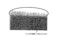
- FIG. 3 is a diagram showing a micrograph showing the printing result of the comparative example.
- the color ink layer did not blur and a highly glossy printed matter was obtained.
- the color ink layer did not blur and a highly glossy printed matter was obtained.
- FIG. 3 in the recording medium in which the clear ink layer was gloss-printed directly on the color ink layer, bleeding occurred at the interface between the color ink layer and the clear ink layer.
- the color ink is prevented from dissolving and bleeding, and the outermost surface of the printed material is glossy. Since it is finished, high gloss is obtained.
- the present invention can be used for inkjet printing.
Landscapes
- Health & Medical Sciences (AREA)
- General Health & Medical Sciences (AREA)
- Toxicology (AREA)
- Ink Jet (AREA)
Abstract
滲みがなく高光沢な印刷物を得ることを課題とする。 解決手段として、インクジェット印刷方法は、記録媒体(10)上に形成された第1インク層(1)上に、第2インクを吐出した後乾燥させる第2インク層形成工程と、第2インク層(2)上に、第3インクを吐出した後乾燥させる第3インク層形成工程とを包含し、第2インク層形成工程における乾燥時間は、第3インク層形成工程における乾燥時間よりも短い。
Description
本発明はインクジェット印刷方法に関する。
紫外線硬化型インクを用いたインクジェット印刷においては、記録媒体上に紫外線硬化型インクを吐出して形成したインク層に紫外線を照射して、インク層を硬化させる。このような紫外線硬化型インクを用いたインクジェット印刷方法として、例えば、特許文献1に記載の印刷方法が知られている。
紫外線硬化型インクには、着色剤を含まない透明な紫外線硬化型インクがあり、クリアインクとして知られている。クリアインクは、カラープリント上のオーバーコート、記録媒体のコーティング等として用いられる。特許文献1に記載されたインクジェット印刷方法により紫外線硬化型インクを印刷媒体に吐出したとき、記録媒体に着弾した直後のインク層表面には凹凸がある。クリアインクをオーバーコート等として用いた場合、その凹凸による反射率の違いから印刷物に光沢ムラが発生する場合がある。
これを防止するため、一定時間経過させてインク層表面の凹凸を平坦化した後、紫外線を照射する対策がなされている。特に、クリアインクをオーバーコートとして用いる場合には、高い光沢性が要求されることから、クリアインク層表面を十分時間をかけて平坦化させる必要がある。
しかしながら、このようにクリアインク層を平坦化させる場合、その過程で、その下層のカラープリント層のインクがクリアインクにより滲み、画像が不鮮明になるという問題がある。
本発明は、上記事情に鑑みてなされたものであり、滲みがなく高光沢な印刷物を得ることができるインクジェット印刷方法を提供することを目的とする。
上記の課題を解決するために、本発明に係るインクジェット印刷方法は、記録媒体上に形成された第1インク層上に、第2インクを吐出した後乾燥させて第2インク層を形成する第2インク層形成工程と、上記第2インク層上に、第3インクを吐出した後乾燥させて第3インク層を形成する第3インク層形成工程とを包含し、上記第2インク層形成工程における乾燥時間は、上記第3インク層形成工程における乾燥時間よりも短いことを特徴としている。
上記の構成によれば、第1インク層に接する第2インク層を形成する第2インク層形成工程において、第2インクを短時間で乾燥させるため、第2インクにより第1インク層のインクが滲むことを素早く防ぐことができる。また、第2インク層上にさらに第3インク層を設け、第3インクを長時間かけて乾燥させるため、第3インク層の表面を十分に平坦化させることができる。これにより、滲みがなく高光沢な印刷物を得ることができる。
また、本発明に係るインクジェット印刷方法において、上記第1インク層を形成する第1インクは、溶剤に可溶なインクであることが好ましい。
上記の構成によれば、第1インク層を、より滲みやすい、溶剤に可溶な第1インクを用いて形成する場合でも、第1インク層に接する第2インク層の形成時に、第2インクを乾燥させる乾燥時間が短いため、滲みがなく高光沢な印刷物を得ることができる。
さらに、本発明に係るインクジェット印刷方法において、上記第2インクと上記第3インクとが同一であることが好ましい。
上記の構成によれば、同一のインクを用いて第2インク層の乾燥時間を第3インク層の乾燥時間より短くするだけで、第2インク層により第1インク層の滲みを防ぎ、第3インク層により印刷物の光沢性が得られるので、滲みがなく高光沢な印刷物を容易に得ることができる。
また、本発明に係るインクジェット印刷方法において、上記第3インクは、クリアインクであることが好ましい。
上記の構成によれば、第3インク層の表面を十分に平坦化させて高い光沢性を得ることができるので、第3インク層としてクリアインクを用いることによって、高光沢なオーバーコートが可能である。
さらに、本発明に係るインクジェット印刷方法において、上記第2インクは、紫外線硬化型インクであることが好ましい。
上記の構成によれば、第2のインク層を、速乾性に優れた紫外線硬化型インクにより形成するため、より滲みのない印刷物を得ることができる。
本発明に係るインクジェット印刷方法は、第1インク層上に第2インク層を形成する第2インク層形成工程における乾燥時間が、第2インク層上に第3インク層を形成する第3インク層形成工程における乾燥時間よりも短いため、第1インク層のインクが溶解して滲むことを防ぐと共に、第3インク層によりコーティングされた、光沢性に優れた印刷物を得ることができる。
以下、本発明の実施の形態について、図1を参照して詳細に説明する。図1は、本発明の一実施形態に係るインクジェット印刷方法を説明する模式図である。本発明の一実施形態に係るインクジェット印刷方法は、記録媒体10上に形成された第1インク層1上に、第2インクを吐出した後乾燥させる第2インク層形成工程と、上記第2インク層2上に、第3インクを吐出した後乾燥させる第3インク層形成工程とを包含している。そして、インクジェット印刷方法において、上記第2インク層形成工程における乾燥時間は、上記第3インク層形成工程における乾燥時間よりも短い。つまり、第2インクを第3インク層形成工程における乾燥時間より短い時間をかけて乾燥させ、第3インクを第2インク層形成工程における乾燥時間より長い時間をかけて乾燥させる。換言すれば、第2インク層は第3インク層よりも、より短い時間で乾燥するものである。
(第1インク層形成工程)
本発明に係るインクジェット印刷方法は、図1中(a)に示すように、記録媒体10上に第1インク層1を形成する第1インク層形成工程をさらに包含していてもよい。第1インク層形成工程においては、記録媒体10に対して、第1インク層1を形成する第1インクを吐出し、乾燥させる。記録媒体10に対する第1インクの吐出は、従来公知のインクジェット印刷装置を用いて好適に行うことができる。また、記録媒体10としては、従来公知の記録メディア等を好適に使用可能である。
本発明に係るインクジェット印刷方法は、図1中(a)に示すように、記録媒体10上に第1インク層1を形成する第1インク層形成工程をさらに包含していてもよい。第1インク層形成工程においては、記録媒体10に対して、第1インク層1を形成する第1インクを吐出し、乾燥させる。記録媒体10に対する第1インクの吐出は、従来公知のインクジェット印刷装置を用いて好適に行うことができる。また、記録媒体10としては、従来公知の記録メディア等を好適に使用可能である。
第1インク層1を形成する第1インクとしては、紫外線硬化型インク、溶剤インク、ラテックスインク等従来公知の種々のインクを用いることが可能であり、着色剤を含有するカラーインクであってもよい。第1インクは、速乾性に優れた紫外線硬化型インクであることが好ましい。
第1インクが紫外線硬化型インクである場合、第1インク層形成工程においては、記録媒体10に対して第1インクを吐出した後、LED等から紫外線を照射することによって、第1インク層1を硬化させればよい。これにより、より短時間で第1インク層1を形成することができる。
また、第1インクは、溶剤に可溶なインクであってもよい。溶剤に可溶なインクとしては、ミマキエンジニアリング社製のLUS-150、LF-140、LF-200、LUS-200等が挙げられる。第1インク層1を、より滲みやすい、溶剤に可溶な第1インクを用いて形成しても、後述するように、第1インク層に接する第2インク層2の形成時に第2インクを乾燥させる乾燥時間が短いため、滲みがなく高光沢な印刷物を得ることができる。
(第2インク層形成工程)
第2インク層形成工程においては、図1中(b)に示すように、記録媒体10上に形成された第1インク層1上に、第2インクを吐出した後乾燥させて第2インク層2を形成する。そして、第2インク層形成工程における乾燥時間は、後述する第3インク層形成工程における乾燥時間よりも短い。第1インク層1に対する第2インクの吐出及び第2インク層2の乾燥は、従来公知のインクジェット印刷装置を用いて好適に行うことができる。
第2インク層形成工程においては、図1中(b)に示すように、記録媒体10上に形成された第1インク層1上に、第2インクを吐出した後乾燥させて第2インク層2を形成する。そして、第2インク層形成工程における乾燥時間は、後述する第3インク層形成工程における乾燥時間よりも短い。第1インク層1に対する第2インクの吐出及び第2インク層2の乾燥は、従来公知のインクジェット印刷装置を用いて好適に行うことができる。
第1インク層に接する第2インク層を形成する第2インク層形成工程において、第2インクを乾燥させて第2インク層を形成するまでの乾燥時間を短くすることによって、第2インクにより第1インク層のインクが滲むことを防ぐことができる。本発明においては、第2インク層2の上にさらに第3インク層を設けるため、第2インクが濡れ広がる時間を経過させずに第2インク層2を乾燥させてその表面に凹凸が形成されたとしても、最表面となる第3インク層の表面が平坦化されることにより高光沢な印刷物を得ることができる。これにより、滲みがなく高光沢な印刷物を得ることができる。
したがって、第2インク層形成工程においては、第2インクが第1インク層1上に着弾すると同時に乾燥させることが好ましい。すなわち、第2インク層形成工程においては、第2インクを吐出しながら第1インク層1上の第2インクを乾燥させることが好ましい。これにより、より確実に第1インク層の滲みを防ぐことができる。
第2インク層2を形成する第2インクとしては、紫外線硬化型インク、ラテックスインク等の従来公知の種々のインクを用いることが可能であり、着色剤を含有するカラーインクであってもよいし、着色剤を含まないクリアインクであってもよい。第2インクは、速乾性に優れた紫外線硬化型インクであることが好ましい。また、第2インク層2を、インク以外の耐溶剤性を有する液体より形成してもよい。第2インク層2は、第3インク層3を形成する第3インクに溶解せず、滲まない層である。
第2インクが紫外線硬化型インクである場合、第2インク層形成工程においては、第1インク層1に対して第2インクを吐出した後又は吐出しながら、LED等から紫外線を照射することによって、第2インク層2を硬化させればよい。これにより、より短時間で第2インク層2を形成することができる。また、第2インクが紫外線硬化型インクであれば、より短時間で第2インク層2を硬化させることができるので、より確実に第1インク層1の滲みを防ぐことができる。
第2インク層2の乾燥に長時間を要すると、第1インク層1に滲みが生じてしまうため、第2インク層形成工程における第2インク層2の乾燥時間は、第1インク層1に滲みが生じない時間であることが好ましい。したがって、第2インクとして第1インクを溶解しやすいインクを用いる場合には、第2インクとして第1インクを溶解しにくいインクを用いる場合よりも乾燥時間を短くすればよい。
第2インク層2の乾燥時間を第3インク層3の乾燥時間よりも短くする方法としては、第2インク層2は、第2インクを吐出した後すぐに乾燥させて形成する一方で、第3インク層3は、第3インクを吐出した後、一定時間経過してから乾燥させて形成するように、インクの吐出と乾燥とを制御する方法が挙げられる。また、第3インク層3よりも第2インク層2の層厚を薄くする方法、溶剤インクを用いる場合には、第3インクよりも速乾性に優れたインクを第2インクとして用いる方法等によっても、第2インク層2の乾燥時間を第3インク層3の乾燥時間よりも短くすることができる。
(第3インク層形成工程)
第3インク層形成工程においては、図1中(c)及び(d)に示すように、第2インク層2上に、第3インクを吐出した後乾燥させて第3インク層3を形成する。そして、第3インク層形成工程における乾燥時間は、第2インク層形成工程における乾燥時間よりも長い。第2インク層2に対する第3インクの吐出及び第3インク層3の乾燥は、従来公知のインクジェット印刷装置を用いて好適に行うことができる。
第3インク層形成工程においては、図1中(c)及び(d)に示すように、第2インク層2上に、第3インクを吐出した後乾燥させて第3インク層3を形成する。そして、第3インク層形成工程における乾燥時間は、第2インク層形成工程における乾燥時間よりも長い。第2インク層2に対する第3インクの吐出及び第3インク層3の乾燥は、従来公知のインクジェット印刷装置を用いて好適に行うことができる。
第3インク層形成工程においては、第3インクが第2インク層2上に着弾した後平坦化するために十分な時間が経過してから、乾燥させることが好ましい。これにより、第3インク層の表面が十分に平坦化し、高光沢な印刷物を得ることができる。
第3インク層3を形成する第3インクとしては、紫外線硬化型インク、溶剤インク、ラテックスインク等の従来公知の種々のインクを用いることが可能であり、着色剤を含有するカラーインクであってもよいし、着色剤を含まないクリアインクであってもよい。第3インク層の表面を十分に平坦化させて高い光沢性を得ることができるので、第3インク層としてクリアインクを用いることによって、高光沢なオーバーコートが可能である。
第3インクが紫外線硬化型インクである場合、第3インク層形成工程においては、第2インク層2に対して第3インクを吐出した後、LED等から紫外線を照射することによって、第3インク層3を硬化させればよい。
第3インクが第2インク層2上に着弾した後、第3インクが濡れ広がるために十分な時間が経過する前に乾燥してしまうと、第3インク層3表面に凹凸が生じ、光沢ムラが発生する場合がある。このため、第3インク層形成工程における第3インクが乾燥して第3インク層が形成するまでの乾燥時間は、第2インク層形成工程における乾燥時間よりも長く、第3インク層3の表面が平坦化するために十分な時間であることが好ましい。
本発明においては、第2インク層2によって、第1インク層1と第3インク層3とが直接接触しないようになっているため、第3インク層3の表面が平坦化するために十分な時間第3インクを濡れ広がらせたとしても、第1インク層1が滲むことがない。したがって、滲みの問題を考慮することなく、第3インクを十分に濡れ広がらせることが可能であり、高光沢な印刷物を得ることができる。
本発明は上述した各実施形態に限定されるものではなく、請求項に示した範囲で種々の変更が可能であり、異なる実施形態にそれぞれ開示された技術的手段を適宜組み合わせて得られる実施形態についても本発明の技術的範囲に含まれる。
〔付記事項〕
本発明に係るインクジェット印刷方法は、記録媒体10上に形成された第1インク層1上に、第2インクを吐出した後乾燥させて第2インク層2を形成する第2インク層形成工程と、第2インク層2上に、第3インクを吐出した後乾燥させて第3インク層3を形成する第3インク層形成工程とを包含し、第2インク層形成工程における乾燥時間は、第3インク層形成工程における乾燥時間よりも短いことを特徴としている。
本発明に係るインクジェット印刷方法は、記録媒体10上に形成された第1インク層1上に、第2インクを吐出した後乾燥させて第2インク層2を形成する第2インク層形成工程と、第2インク層2上に、第3インクを吐出した後乾燥させて第3インク層3を形成する第3インク層形成工程とを包含し、第2インク層形成工程における乾燥時間は、第3インク層形成工程における乾燥時間よりも短いことを特徴としている。
上記の構成によれば、第1インク層1に接する第2インク層2を形成する第2インク層形成工程において、第2インクを短時間で乾燥させるため、第2インクにより第1インク層1のインクが滲むことを防ぐことができる。また、第2インク層2上にさらに第3インク層3を設け、第3インクを長時間かけて乾燥させるため、第3インク層3の表面を十分に平坦化させることができる。これにより、滲みがなく高光沢な印刷物を得ることができる。
また、本発明に係るインクジェット印刷方法において、第1インク層1を形成する第1インクは、溶剤に可溶なインクである。
上記の構成によれば、第1インク層1を、より滲みやすい、溶剤に可溶な第1インクを用いて形成する場合でも、第1インク層1に接する第2インク層2の形成時に、第2インクを乾燥させる乾燥時間が短いため、滲みがなく高光沢な印刷物を得ることができる。
さらに、本発明に係るインクジェット印刷方法において、第2インクと第3インクとが同一である。
上記の構成によれば、同一のインクを用いて第2インク層2の乾燥時間を第3インク層3の乾燥時間より短くするだけで、第2インク層2により第1インク層1の滲みを防ぎ、第3インク層3により印刷物の光沢性が得られるので、滲みがなく高光沢な印刷物を容易に得ることができる。
また、本発明に係るインクジェット印刷方法において、第3インクは、クリアインクである。
上記の構成によれば、第3インク層3の表面を十分に平坦化させて高い光沢性を得ることができるので、第3インク層3としてクリアインクを用いることによって、高光沢なオーバーコートが可能である。
さらに、本発明に係るインクジェット印刷方法において、第2インクは、紫外線硬化型インクである。
上記の構成によれば、第2インク層2を、速乾性に優れた紫外線硬化型インクにより形成するため、より滲みのない印刷物を得ることができる。
本発明の一実施例について図2及び図3に基づいて説明すれば以下のとおりである。
インクジェットプリンタとして、UJF-3042(ミマキエンジニアリング社製、ヘッド温度:45℃)を用い、記録媒体としてU292W(帝人デュポンフィルム社製)を用い、印刷物を評価した。
2つの記録媒体のそれぞれに、LUS-150(ミマキエンジニアリング社製)のシアン、マゼンダ、イエロー及びブラックの4色を吐出して、カラーインク層を形成した。第1インク層の印刷条件は、720×600dpi/8pass、積算光量:120mJ/cm2とした。
次に、カラーインク層上にLH-100CL(ミマキエンジニアリング社製)を吐出し、クリアインク層を形成した。一方の記録媒体上のカラーインク層にクリアインク層をマット印刷(印刷条件:720×600dpi/4pass)し、他方の記録媒体上のカラーインク層にはクリアインク層をグロス印刷した(印刷条件:720×600dpi/4pass)。記録媒体へのインクの吐出及びインクの乾燥に要する時間を印刷時間とした場合、縦42cm×横30cmの記録媒体に対する印刷時間は、マット印刷においては約1分間であったのに対して、グロス印刷においては約2分間であった。すなわち、マット印刷における乾燥時間はグロス印刷における乾燥時間よりも短かった。クリアインク層をマット印刷した方の記録媒体には、さらに、クリアインク層上にLH-100CLを用いてグロス印刷した。
結果を図2及び図3に示す。図2は、実施例の印刷結果を表す顕微鏡写真を示す図であり、図3は、比較例の印刷結果を表す顕微鏡写真を示す図である。図2に示すように、カラーインク層上にクリアインク層をマット印刷した後、さらにグロス印刷した記録媒体においては、カラーインク層の滲みがなく、光沢性の高い印刷物が得られた。一方、図3に示すように、カラーインク層上に直接クリアインク層をグロス印刷した記録媒体においては、カラーインク層とクリアインク層との界面において滲みが生じた。
このように、カラーインク層とグロス印刷したクリアインク層との間に、クリアインクによりマット印刷した層を設けることによって、カラーインクが溶解して滲むことを防ぎ、また、印刷物の最表面はグロス仕上げされるため、高い光沢性が得られる。
本発明は、インクジェット印刷に利用することができる。
1 第1インク層
2 第2インク層
3 第3インク層
10 記録媒体
2 第2インク層
3 第3インク層
10 記録媒体
Claims (5)
- 記録媒体上に形成された第1インク層上に、第2インクを吐出した後乾燥させて第2インク層を形成する第2インク層形成工程と、
上記第2インク層上に、第3インクを吐出した後乾燥させて第3インク層を形成する第3インク層形成工程と
を包含し、
上記第2インク層形成工程における乾燥時間は、上記第3インク層形成工程における乾燥時間よりも短いことを特徴とするインクジェット印刷方法。 - 上記第1インク層を形成する第1インクは、溶剤に可溶なインクであることを特徴とする請求項1に記載のインクジェット印刷方法。
- 上記第2インクと上記第3インクとが同一であることを特徴とする請求項1又は2に記載のインクジェット印刷方法。
- 上記第3インクは、クリアインクであることを特徴とする請求項1又は2に記載のインクジェット印刷方法。
- 上記第2インクは、紫外線硬化型インクであることを特徴とする請求項1又は2に記載のインクジェット印刷方法。
Priority Applications (3)
| Application Number | Priority Date | Filing Date | Title |
|---|---|---|---|
| US15/027,428 US9827789B2 (en) | 2013-10-07 | 2014-09-29 | Inkjet printing method |
| EP14852916.7A EP3042770A4 (en) | 2013-10-07 | 2014-09-29 | Inkjet printing method |
| CN201480055315.4A CN105636788A (zh) | 2013-10-07 | 2014-09-29 | 喷墨打印方法 |
Applications Claiming Priority (2)
| Application Number | Priority Date | Filing Date | Title |
|---|---|---|---|
| JP2013210575A JP2015074120A (ja) | 2013-10-07 | 2013-10-07 | インクジェット印刷方法 |
| JP2013-210575 | 2013-10-07 |
Publications (1)
| Publication Number | Publication Date |
|---|---|
| WO2015053104A1 true WO2015053104A1 (ja) | 2015-04-16 |
Family
ID=52812923
Family Applications (1)
| Application Number | Title | Priority Date | Filing Date |
|---|---|---|---|
| PCT/JP2014/075780 Ceased WO2015053104A1 (ja) | 2013-10-07 | 2014-09-29 | インクジェット印刷方法 |
Country Status (5)
| Country | Link |
|---|---|
| US (1) | US9827789B2 (ja) |
| EP (1) | EP3042770A4 (ja) |
| JP (1) | JP2015074120A (ja) |
| CN (1) | CN105636788A (ja) |
| WO (1) | WO2015053104A1 (ja) |
Families Citing this family (8)
| Publication number | Priority date | Publication date | Assignee | Title |
|---|---|---|---|---|
| WO2017104845A1 (ja) | 2015-12-18 | 2017-06-22 | 富士フイルム株式会社 | インクジェット記録方法及びインクジェット記録装置 |
| CN108884348B (zh) | 2016-03-31 | 2021-06-08 | 富士胶片株式会社 | 油墨组以及图像形成方法 |
| JP2018176581A (ja) * | 2017-04-14 | 2018-11-15 | 株式会社ミマキエンジニアリング | メディア及びメディアの製造方法 |
| JP2019072914A (ja) * | 2017-10-16 | 2019-05-16 | 株式会社ミマキエンジニアリング | 立体模様印刷物の製造方法 |
| CN109703194B (zh) * | 2018-12-29 | 2020-11-24 | 东莞市图创智能制造有限公司 | 透明油墨固化方法、装置、设备及系统 |
| GB2584330A (en) * | 2019-05-31 | 2020-12-02 | Vivid Laminating Tech Ltd | Processes for applying transfer material to a substrate surface |
| JP7596657B2 (ja) * | 2020-07-31 | 2024-12-10 | セイコーエプソン株式会社 | インクジェット記録方法及びインクジェット記録装置 |
| JP2022055502A (ja) * | 2020-09-29 | 2022-04-08 | 武藤工業株式会社 | インクジェットプリンタによるクリアインクの印刷方法 |
Citations (8)
| Publication number | Priority date | Publication date | Assignee | Title |
|---|---|---|---|---|
| JP2004358769A (ja) | 2003-06-04 | 2004-12-24 | Mimaki Engineering Co Ltd | Uvインク使用のインクジェットプリンタ |
| JP2006015691A (ja) * | 2004-07-05 | 2006-01-19 | Mimaki Engineering Co Ltd | Uv硬化型インク使用のインクジェットプリンタを用いたプリント方法と該方法に用いるuv硬化型インク使用のインクジェットプリンタ |
| JP2010006027A (ja) * | 2008-06-30 | 2010-01-14 | Seiko Epson Corp | 流体噴射装置、及び画像形成方法 |
| JP2010195002A (ja) * | 2009-02-27 | 2010-09-09 | Mimaki Engineering Co Ltd | インクジェットプリンタ及びプリント方法 |
| JP2011177967A (ja) * | 2010-02-26 | 2011-09-15 | Canon Inc | インクジェット記録装置およびインクジェット記録方法 |
| JP2011189594A (ja) * | 2010-03-15 | 2011-09-29 | Seiko Epson Corp | 印刷装置 |
| JP2012106473A (ja) * | 2010-10-22 | 2012-06-07 | Mimaki Engineering Co Ltd | インクジェット記録装置 |
| JP2013022943A (ja) * | 2011-07-26 | 2013-02-04 | Seiko Epson Corp | 印刷装置及び印刷方法 |
Family Cites Families (2)
| Publication number | Priority date | Publication date | Assignee | Title |
|---|---|---|---|---|
| US5165967A (en) * | 1990-09-24 | 1992-11-24 | Brown Printing Co., A Division Of Gruner & Jahr Publishing Co. | Method for producing article with different gloss surfaces |
| EP2682268B1 (en) | 2011-03-04 | 2017-02-15 | Mimaki Engineering Co., Ltd. | Inkjet recording device |
-
2013
- 2013-10-07 JP JP2013210575A patent/JP2015074120A/ja active Pending
-
2014
- 2014-09-29 EP EP14852916.7A patent/EP3042770A4/en not_active Withdrawn
- 2014-09-29 WO PCT/JP2014/075780 patent/WO2015053104A1/ja not_active Ceased
- 2014-09-29 CN CN201480055315.4A patent/CN105636788A/zh active Pending
- 2014-09-29 US US15/027,428 patent/US9827789B2/en active Active
Patent Citations (8)
| Publication number | Priority date | Publication date | Assignee | Title |
|---|---|---|---|---|
| JP2004358769A (ja) | 2003-06-04 | 2004-12-24 | Mimaki Engineering Co Ltd | Uvインク使用のインクジェットプリンタ |
| JP2006015691A (ja) * | 2004-07-05 | 2006-01-19 | Mimaki Engineering Co Ltd | Uv硬化型インク使用のインクジェットプリンタを用いたプリント方法と該方法に用いるuv硬化型インク使用のインクジェットプリンタ |
| JP2010006027A (ja) * | 2008-06-30 | 2010-01-14 | Seiko Epson Corp | 流体噴射装置、及び画像形成方法 |
| JP2010195002A (ja) * | 2009-02-27 | 2010-09-09 | Mimaki Engineering Co Ltd | インクジェットプリンタ及びプリント方法 |
| JP2011177967A (ja) * | 2010-02-26 | 2011-09-15 | Canon Inc | インクジェット記録装置およびインクジェット記録方法 |
| JP2011189594A (ja) * | 2010-03-15 | 2011-09-29 | Seiko Epson Corp | 印刷装置 |
| JP2012106473A (ja) * | 2010-10-22 | 2012-06-07 | Mimaki Engineering Co Ltd | インクジェット記録装置 |
| JP2013022943A (ja) * | 2011-07-26 | 2013-02-04 | Seiko Epson Corp | 印刷装置及び印刷方法 |
Non-Patent Citations (1)
| Title |
|---|
| See also references of EP3042770A4 * |
Also Published As
| Publication number | Publication date |
|---|---|
| US9827789B2 (en) | 2017-11-28 |
| JP2015074120A (ja) | 2015-04-20 |
| EP3042770A1 (en) | 2016-07-13 |
| US20160250864A1 (en) | 2016-09-01 |
| EP3042770A4 (en) | 2017-01-11 |
| CN105636788A (zh) | 2016-06-01 |
Similar Documents
| Publication | Publication Date | Title |
|---|---|---|
| WO2015053104A1 (ja) | インクジェット印刷方法 | |
| JP6494454B2 (ja) | インクジェット記録方法及びインクジェット記録装置 | |
| CN108472974B (zh) | 墨水组、及印刷物的制造方法 | |
| US7942516B2 (en) | Image forming method and image forming apparatus | |
| CN106042668B (zh) | 印刷装置以及印刷装置的控制方法 | |
| US20190232684A1 (en) | Printing apparatus and printing method | |
| JP7131241B2 (ja) | インクジェット記録方法、インクジェット記録装置 | |
| JP2004090596A (ja) | 画像形成方法及び画像形成装置 | |
| JP2017071662A (ja) | インキセット及び印刷物の製造方法 | |
| CN104245338A (zh) | 打印方法 | |
| JP6462374B2 (ja) | 印刷装置、及び印刷方法 | |
| JP7103808B2 (ja) | 印刷装置及び印刷方法 | |
| JP6370448B2 (ja) | インクジェット印刷方法 | |
| JP2017534478A (ja) | 印刷方法 | |
| JP6976655B2 (ja) | 印刷装置及び印刷方法 | |
| US20130335494A1 (en) | Digital inkjet printing machine with transparent ink | |
| JP2016199700A (ja) | インクセット及びインクジェット記録方法 | |
| JP4642737B2 (ja) | インクジェット記録方法およびインクジェット記録装置 | |
| JP2010260237A (ja) | 記録装置および判定方法 | |
| JP7119740B2 (ja) | 化粧板印刷紙の製造方法、化粧板の製造方法、化粧板印刷紙の製造装置、印刷媒体の製造方法、積層構造体の製造方法、および積層構造体の製造装置 | |
| WO2020022118A1 (ja) | 記録装置および記録方法 | |
| JP2019209500A (ja) | 印刷方法、印刷装置、収容容器セット、及び印刷物 | |
| JP2014014939A (ja) | インクジェット記録媒体、およびインクジェット記録方法 | |
| JP2023107416A5 (ja) | 画像形成装置 | |
| JP2019025874A (ja) | 印刷方法、印刷装置、及び印刷システム |
Legal Events
| Date | Code | Title | Description |
|---|---|---|---|
| 121 | Ep: the epo has been informed by wipo that ep was designated in this application |
Ref document number: 14852916 Country of ref document: EP Kind code of ref document: A1 |
|
| REEP | Request for entry into the european phase |
Ref document number: 2014852916 Country of ref document: EP |
|
| WWE | Wipo information: entry into national phase |
Ref document number: 2014852916 Country of ref document: EP |
|
| WWE | Wipo information: entry into national phase |
Ref document number: 15027428 Country of ref document: US |
|
| NENP | Non-entry into the national phase |
Ref country code: DE |