WO2015064329A1 - 配線モジュール - Google Patents
配線モジュール Download PDFInfo
- Publication number
- WO2015064329A1 WO2015064329A1 PCT/JP2014/077047 JP2014077047W WO2015064329A1 WO 2015064329 A1 WO2015064329 A1 WO 2015064329A1 JP 2014077047 W JP2014077047 W JP 2014077047W WO 2015064329 A1 WO2015064329 A1 WO 2015064329A1
- Authority
- WO
- WIPO (PCT)
- Prior art keywords
- bus bar
- electronic control
- control unit
- wiring module
- power storage
- Prior art date
- Legal status (The legal status is an assumption and is not a legal conclusion. Google has not performed a legal analysis and makes no representation as to the accuracy of the status listed.)
- Ceased
Links
Images






Classifications
-
- H—ELECTRICITY
- H01—ELECTRIC ELEMENTS
- H01M—PROCESSES OR MEANS, e.g. BATTERIES, FOR THE DIRECT CONVERSION OF CHEMICAL ENERGY INTO ELECTRICAL ENERGY
- H01M10/00—Secondary cells; Manufacture thereof
- H01M10/42—Methods or arrangements for servicing or maintenance of secondary cells or secondary half-cells
- H01M10/425—Structural combination with electronic components, e.g. electronic circuits integrated to the outside of the casing
-
- B—PERFORMING OPERATIONS; TRANSPORTING
- B60—VEHICLES IN GENERAL
- B60L—PROPULSION OF ELECTRICALLY-PROPELLED VEHICLES; SUPPLYING ELECTRIC POWER FOR AUXILIARY EQUIPMENT OF ELECTRICALLY-PROPELLED VEHICLES; ELECTRODYNAMIC BRAKE SYSTEMS FOR VEHICLES IN GENERAL; MAGNETIC SUSPENSION OR LEVITATION FOR VEHICLES; MONITORING OPERATING VARIABLES OF ELECTRICALLY-PROPELLED VEHICLES; ELECTRIC SAFETY DEVICES FOR ELECTRICALLY-PROPELLED VEHICLES
- B60L50/00—Electric propulsion with power supplied within the vehicle
- B60L50/50—Electric propulsion with power supplied within the vehicle using propulsion power supplied by batteries or fuel cells
- B60L50/60—Electric propulsion with power supplied within the vehicle using propulsion power supplied by batteries or fuel cells using power supplied by batteries
- B60L50/64—Constructional details of batteries specially adapted for electric vehicles
-
- B—PERFORMING OPERATIONS; TRANSPORTING
- B60—VEHICLES IN GENERAL
- B60L—PROPULSION OF ELECTRICALLY-PROPELLED VEHICLES; SUPPLYING ELECTRIC POWER FOR AUXILIARY EQUIPMENT OF ELECTRICALLY-PROPELLED VEHICLES; ELECTRODYNAMIC BRAKE SYSTEMS FOR VEHICLES IN GENERAL; MAGNETIC SUSPENSION OR LEVITATION FOR VEHICLES; MONITORING OPERATING VARIABLES OF ELECTRICALLY-PROPELLED VEHICLES; ELECTRIC SAFETY DEVICES FOR ELECTRICALLY-PROPELLED VEHICLES
- B60L58/00—Methods or circuit arrangements for monitoring or controlling batteries or fuel cells, specially adapted for electric vehicles
- B60L58/10—Methods or circuit arrangements for monitoring or controlling batteries or fuel cells, specially adapted for electric vehicles for monitoring or controlling batteries
- B60L58/18—Methods or circuit arrangements for monitoring or controlling batteries or fuel cells, specially adapted for electric vehicles for monitoring or controlling batteries of two or more battery modules
- B60L58/21—Methods or circuit arrangements for monitoring or controlling batteries or fuel cells, specially adapted for electric vehicles for monitoring or controlling batteries of two or more battery modules having the same nominal voltage
-
- H—ELECTRICITY
- H01—ELECTRIC ELEMENTS
- H01M—PROCESSES OR MEANS, e.g. BATTERIES, FOR THE DIRECT CONVERSION OF CHEMICAL ENERGY INTO ELECTRICAL ENERGY
- H01M10/00—Secondary cells; Manufacture thereof
- H01M10/42—Methods or arrangements for servicing or maintenance of secondary cells or secondary half-cells
- H01M10/48—Accumulators combined with arrangements for measuring, testing or indicating the condition of cells, e.g. the level or density of the electrolyte
- H01M10/482—Accumulators combined with arrangements for measuring, testing or indicating the condition of cells, e.g. the level or density of the electrolyte for several batteries or cells simultaneously or sequentially
-
- H—ELECTRICITY
- H01—ELECTRIC ELEMENTS
- H01M—PROCESSES OR MEANS, e.g. BATTERIES, FOR THE DIRECT CONVERSION OF CHEMICAL ENERGY INTO ELECTRICAL ENERGY
- H01M50/00—Constructional details or processes of manufacture of the non-active parts of electrochemical cells other than fuel cells, e.g. hybrid cells
- H01M50/20—Mountings; Secondary casings or frames; Racks, modules or packs; Suspension devices; Shock absorbers; Transport or carrying devices; Holders
- H01M50/204—Racks, modules or packs for multiple batteries or multiple cells
- H01M50/207—Racks, modules or packs for multiple batteries or multiple cells characterised by their shape
- H01M50/209—Racks, modules or packs for multiple batteries or multiple cells characterised by their shape adapted for prismatic or rectangular cells
-
- H—ELECTRICITY
- H01—ELECTRIC ELEMENTS
- H01M—PROCESSES OR MEANS, e.g. BATTERIES, FOR THE DIRECT CONVERSION OF CHEMICAL ENERGY INTO ELECTRICAL ENERGY
- H01M50/00—Constructional details or processes of manufacture of the non-active parts of electrochemical cells other than fuel cells, e.g. hybrid cells
- H01M50/20—Mountings; Secondary casings or frames; Racks, modules or packs; Suspension devices; Shock absorbers; Transport or carrying devices; Holders
- H01M50/244—Secondary casings; Racks; Suspension devices; Carrying devices; Holders characterised by their mounting method
-
- H—ELECTRICITY
- H01—ELECTRIC ELEMENTS
- H01M—PROCESSES OR MEANS, e.g. BATTERIES, FOR THE DIRECT CONVERSION OF CHEMICAL ENERGY INTO ELECTRICAL ENERGY
- H01M50/00—Constructional details or processes of manufacture of the non-active parts of electrochemical cells other than fuel cells, e.g. hybrid cells
- H01M50/20—Mountings; Secondary casings or frames; Racks, modules or packs; Suspension devices; Shock absorbers; Transport or carrying devices; Holders
- H01M50/262—Mountings; Secondary casings or frames; Racks, modules or packs; Suspension devices; Shock absorbers; Transport or carrying devices; Holders with fastening means, e.g. locks
-
- H—ELECTRICITY
- H01—ELECTRIC ELEMENTS
- H01M—PROCESSES OR MEANS, e.g. BATTERIES, FOR THE DIRECT CONVERSION OF CHEMICAL ENERGY INTO ELECTRICAL ENERGY
- H01M50/00—Constructional details or processes of manufacture of the non-active parts of electrochemical cells other than fuel cells, e.g. hybrid cells
- H01M50/20—Mountings; Secondary casings or frames; Racks, modules or packs; Suspension devices; Shock absorbers; Transport or carrying devices; Holders
- H01M50/284—Mountings; Secondary casings or frames; Racks, modules or packs; Suspension devices; Shock absorbers; Transport or carrying devices; Holders with incorporated circuit boards, e.g. printed circuit boards [PCB]
-
- H—ELECTRICITY
- H01—ELECTRIC ELEMENTS
- H01M—PROCESSES OR MEANS, e.g. BATTERIES, FOR THE DIRECT CONVERSION OF CHEMICAL ENERGY INTO ELECTRICAL ENERGY
- H01M50/00—Constructional details or processes of manufacture of the non-active parts of electrochemical cells other than fuel cells, e.g. hybrid cells
- H01M50/20—Mountings; Secondary casings or frames; Racks, modules or packs; Suspension devices; Shock absorbers; Transport or carrying devices; Holders
- H01M50/298—Mountings; Secondary casings or frames; Racks, modules or packs; Suspension devices; Shock absorbers; Transport or carrying devices; Holders characterised by the wiring of battery packs
-
- H—ELECTRICITY
- H01—ELECTRIC ELEMENTS
- H01M—PROCESSES OR MEANS, e.g. BATTERIES, FOR THE DIRECT CONVERSION OF CHEMICAL ENERGY INTO ELECTRICAL ENERGY
- H01M50/00—Constructional details or processes of manufacture of the non-active parts of electrochemical cells other than fuel cells, e.g. hybrid cells
- H01M50/30—Arrangements for facilitating escape of gases
-
- H—ELECTRICITY
- H01—ELECTRIC ELEMENTS
- H01M—PROCESSES OR MEANS, e.g. BATTERIES, FOR THE DIRECT CONVERSION OF CHEMICAL ENERGY INTO ELECTRICAL ENERGY
- H01M50/00—Constructional details or processes of manufacture of the non-active parts of electrochemical cells other than fuel cells, e.g. hybrid cells
- H01M50/30—Arrangements for facilitating escape of gases
- H01M50/308—Detachable arrangements, e.g. detachable vent plugs or plug systems
-
- H—ELECTRICITY
- H01—ELECTRIC ELEMENTS
- H01M—PROCESSES OR MEANS, e.g. BATTERIES, FOR THE DIRECT CONVERSION OF CHEMICAL ENERGY INTO ELECTRICAL ENERGY
- H01M50/00—Constructional details or processes of manufacture of the non-active parts of electrochemical cells other than fuel cells, e.g. hybrid cells
- H01M50/50—Current conducting connections for cells or batteries
- H01M50/502—Interconnectors for connecting terminals of adjacent batteries; Interconnectors for connecting cells outside a battery casing
- H01M50/507—Interconnectors for connecting terminals of adjacent batteries; Interconnectors for connecting cells outside a battery casing comprising an arrangement of two or more busbars within a container structure, e.g. busbar modules
-
- H—ELECTRICITY
- H01—ELECTRIC ELEMENTS
- H01M—PROCESSES OR MEANS, e.g. BATTERIES, FOR THE DIRECT CONVERSION OF CHEMICAL ENERGY INTO ELECTRICAL ENERGY
- H01M50/00—Constructional details or processes of manufacture of the non-active parts of electrochemical cells other than fuel cells, e.g. hybrid cells
- H01M50/50—Current conducting connections for cells or batteries
- H01M50/502—Interconnectors for connecting terminals of adjacent batteries; Interconnectors for connecting cells outside a battery casing
- H01M50/521—Interconnectors for connecting terminals of adjacent batteries; Interconnectors for connecting cells outside a battery casing characterised by the material
- H01M50/522—Inorganic material
-
- H—ELECTRICITY
- H01—ELECTRIC ELEMENTS
- H01M—PROCESSES OR MEANS, e.g. BATTERIES, FOR THE DIRECT CONVERSION OF CHEMICAL ENERGY INTO ELECTRICAL ENERGY
- H01M50/00—Constructional details or processes of manufacture of the non-active parts of electrochemical cells other than fuel cells, e.g. hybrid cells
- H01M50/50—Current conducting connections for cells or batteries
- H01M50/569—Constructional details of current conducting connections for detecting conditions inside cells or batteries, e.g. details of voltage sensing terminals
-
- B—PERFORMING OPERATIONS; TRANSPORTING
- B60—VEHICLES IN GENERAL
- B60L—PROPULSION OF ELECTRICALLY-PROPELLED VEHICLES; SUPPLYING ELECTRIC POWER FOR AUXILIARY EQUIPMENT OF ELECTRICALLY-PROPELLED VEHICLES; ELECTRODYNAMIC BRAKE SYSTEMS FOR VEHICLES IN GENERAL; MAGNETIC SUSPENSION OR LEVITATION FOR VEHICLES; MONITORING OPERATING VARIABLES OF ELECTRICALLY-PROPELLED VEHICLES; ELECTRIC SAFETY DEVICES FOR ELECTRICALLY-PROPELLED VEHICLES
- B60L2240/00—Control parameters of input or output; Target parameters
- B60L2240/40—Drive Train control parameters
- B60L2240/54—Drive Train control parameters related to batteries
- B60L2240/545—Temperature
-
- B—PERFORMING OPERATIONS; TRANSPORTING
- B60—VEHICLES IN GENERAL
- B60L—PROPULSION OF ELECTRICALLY-PROPELLED VEHICLES; SUPPLYING ELECTRIC POWER FOR AUXILIARY EQUIPMENT OF ELECTRICALLY-PROPELLED VEHICLES; ELECTRODYNAMIC BRAKE SYSTEMS FOR VEHICLES IN GENERAL; MAGNETIC SUSPENSION OR LEVITATION FOR VEHICLES; MONITORING OPERATING VARIABLES OF ELECTRICALLY-PROPELLED VEHICLES; ELECTRIC SAFETY DEVICES FOR ELECTRICALLY-PROPELLED VEHICLES
- B60L2240/00—Control parameters of input or output; Target parameters
- B60L2240/40—Drive Train control parameters
- B60L2240/54—Drive Train control parameters related to batteries
- B60L2240/547—Voltage
-
- B—PERFORMING OPERATIONS; TRANSPORTING
- B60—VEHICLES IN GENERAL
- B60L—PROPULSION OF ELECTRICALLY-PROPELLED VEHICLES; SUPPLYING ELECTRIC POWER FOR AUXILIARY EQUIPMENT OF ELECTRICALLY-PROPELLED VEHICLES; ELECTRODYNAMIC BRAKE SYSTEMS FOR VEHICLES IN GENERAL; MAGNETIC SUSPENSION OR LEVITATION FOR VEHICLES; MONITORING OPERATING VARIABLES OF ELECTRICALLY-PROPELLED VEHICLES; ELECTRIC SAFETY DEVICES FOR ELECTRICALLY-PROPELLED VEHICLES
- B60L2240/00—Control parameters of input or output; Target parameters
- B60L2240/40—Drive Train control parameters
- B60L2240/54—Drive Train control parameters related to batteries
- B60L2240/549—Current
-
- H—ELECTRICITY
- H01—ELECTRIC ELEMENTS
- H01M—PROCESSES OR MEANS, e.g. BATTERIES, FOR THE DIRECT CONVERSION OF CHEMICAL ENERGY INTO ELECTRICAL ENERGY
- H01M2220/00—Batteries for particular applications
- H01M2220/20—Batteries in motive systems, e.g. vehicle, ship, plane
-
- H—ELECTRICITY
- H01—ELECTRIC ELEMENTS
- H01M—PROCESSES OR MEANS, e.g. BATTERIES, FOR THE DIRECT CONVERSION OF CHEMICAL ENERGY INTO ELECTRICAL ENERGY
- H01M50/00—Constructional details or processes of manufacture of the non-active parts of electrochemical cells other than fuel cells, e.g. hybrid cells
- H01M50/20—Mountings; Secondary casings or frames; Racks, modules or packs; Suspension devices; Shock absorbers; Transport or carrying devices; Holders
- H01M50/271—Lids or covers for the racks or secondary casings
-
- H—ELECTRICITY
- H01—ELECTRIC ELEMENTS
- H01M—PROCESSES OR MEANS, e.g. BATTERIES, FOR THE DIRECT CONVERSION OF CHEMICAL ENERGY INTO ELECTRICAL ENERGY
- H01M50/00—Constructional details or processes of manufacture of the non-active parts of electrochemical cells other than fuel cells, e.g. hybrid cells
- H01M50/30—Arrangements for facilitating escape of gases
- H01M50/342—Non-re-sealable arrangements
- H01M50/3425—Non-re-sealable arrangements in the form of rupturable membranes or weakened parts, e.g. pierced with the aid of a sharp member
-
- Y—GENERAL TAGGING OF NEW TECHNOLOGICAL DEVELOPMENTS; GENERAL TAGGING OF CROSS-SECTIONAL TECHNOLOGIES SPANNING OVER SEVERAL SECTIONS OF THE IPC; TECHNICAL SUBJECTS COVERED BY FORMER USPC CROSS-REFERENCE ART COLLECTIONS [XRACs] AND DIGESTS
- Y02—TECHNOLOGIES OR APPLICATIONS FOR MITIGATION OR ADAPTATION AGAINST CLIMATE CHANGE
- Y02E—REDUCTION OF GREENHOUSE GAS [GHG] EMISSIONS, RELATED TO ENERGY GENERATION, TRANSMISSION OR DISTRIBUTION
- Y02E60/00—Enabling technologies; Technologies with a potential or indirect contribution to GHG emissions mitigation
- Y02E60/10—Energy storage using batteries
-
- Y—GENERAL TAGGING OF NEW TECHNOLOGICAL DEVELOPMENTS; GENERAL TAGGING OF CROSS-SECTIONAL TECHNOLOGIES SPANNING OVER SEVERAL SECTIONS OF THE IPC; TECHNICAL SUBJECTS COVERED BY FORMER USPC CROSS-REFERENCE ART COLLECTIONS [XRACs] AND DIGESTS
- Y02—TECHNOLOGIES OR APPLICATIONS FOR MITIGATION OR ADAPTATION AGAINST CLIMATE CHANGE
- Y02T—CLIMATE CHANGE MITIGATION TECHNOLOGIES RELATED TO TRANSPORTATION
- Y02T10/00—Road transport of goods or passengers
- Y02T10/60—Other road transportation technologies with climate change mitigation effect
- Y02T10/70—Energy storage systems for electromobility, e.g. batteries
Definitions
- the present invention relates to a wiring module.
- Battery modules for electric vehicles and hybrid vehicles are configured by arranging a plurality of single cells having positive and negative electrode terminals side by side. By connecting the electrode terminals of a plurality of single cells with a bus bar, the plurality of single cells are connected in series or in parallel.
- Patent Document 1 discloses a wiring module having a configuration in which a plurality of resin bus bar insulating members are connected to each other via a bus bar. According to the configuration described in Patent Document 1, since the two bus bar insulating members connected via the bus bar are movable relative to the bus bar, manufacturing between the electrode terminals of a plurality of single cells is possible. Tolerances and assembly tolerances can be absorbed.
- a voltage detection terminal for detecting the voltage of each unit cell is superimposed on each bus bar connected to the unit cell.
- This voltage detection terminal is connected to one end side (core wire) of the electric wire, and the other end side is pulled out of the battery module and connected to an ECU (electronic control unit) etc. Detected.
- the ECU is assembled to the wiring module to shorten the distance of the electric wires.
- the ECU is fixed to the wiring module capable of absorbing the manufacturing tolerance and the assembly tolerance between the electrode terminals of the plurality of single cells as described above, the relative movement of the bus bar connecting member is restricted by the ECU. The tolerance cannot be absorbed, and there is a concern that problems may occur when the wiring module is attached to the unit cell group.
- the present invention has been completed based on the above-described circumstances, and provides a wiring module in which, even when an electronic control unit is assembled, it is possible to prevent a problem from occurring when the electronic control unit is attached. For the purpose.
- the present invention for solving the above-described problems is a wiring module attached to a power storage element group in which a plurality of power storage elements having positive and negative electrode terminals are arranged in an array direction, and is adjacent to each other among the plurality of power storage elements.
- a connecting member that electrically connects the electrode terminals of the storage element; a holding member that holds the connection member; and a holding member made of an insulating resin that is attached to the storage element group; and the plurality of storage elements
- An electronic control unit that detects a state of at least one power storage element, wherein the holding member is configured to absorb tolerances in the arrangement direction of the plurality of power storage elements, and the electronic control unit includes the electronic control unit,
- the holding member is attached to the holding member so as to be relatively movable in the arrangement direction with respect to the holding member.
- the electronic control unit is movable relative to the holding member in the alignment direction.
- the holding member intersects the storage element group in the arrangement direction of the plurality of storage elements without being restricted by the electronic control unit. Can be absorbed.
- the wiring module preferably has the following configuration.
- the electronic control unit houses a detection circuit that detects a state of at least one of the plurality of power storage elements in a case, and the case and the holding member are locking pieces provided on one side. Further, the case and the holding member are relatively movable in the arrangement direction between the locking piece and the locking portion. It is good also as a structure provided with the clearance.
- the electronic control unit is integrated with the holding member by the locking pieces and the locking portions provided on the case and the holding member.
- a clearance is provided between the case and the holding member. With the above clearance, the electronic control unit is attached to the holding member so as to be movable in the alignment direction.
- the electronic control unit may be fixed to the duct by providing a duct that vents a gas generated inside at least one of the plurality of power storage elements and exhausts the gas to the outside.
- the electronic control unit is movably attached to the holding member, while being fixed to the duct, the entire wiring module can be made stable.
- the duct may be configured to be attachable to the power storage element group.
- the wiring module can be more stably attached to the power storage element group.
- connection piece includes the plurality of the connection pieces. It is good also as a structure which has the tolerance absorption part which absorbs the tolerance about the said alignment direction of an electrical storage element.
- connection piece even when the connection between the detection member and the electronic control unit is performed by the connection piece integrally provided on the detection member, the connection piece has a tolerance in the arrangement direction of the storage elements. Since it has the tolerance absorption part which absorbs, relative movement of a detection member and an electronic control unit is attained.
- Such a tolerance absorbing part can be easily manufactured by punching a plate material together with the main body part.
- the electronic control unit further includes a detection circuit board on which a detection circuit for detecting a state of at least one of the plurality of storage elements is formed, and the plurality of detection members include the connection piece. It is good also as a structure attached to the said detection circuit board collectively with the positioning member which can be put in a predetermined position and hold
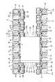
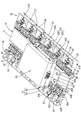
- FIG. 1 is an exploded perspective view of a battery module according to Embodiment 1.
- the disassembled perspective view of the wiring module of Embodiment 2 Disassembled perspective view of battery module Battery module perspective view
- FIG. 17 is a partially enlarged perspective view of FIG.
- Partial enlarged plan view of battery wiring module EE sectional view of FIG. FF sectional view of FIG. The perspective view which shows the process in which the voltage detection bus-bar integrated with the positioning member is attached to a detection circuit board
- the perspective view which shows the process in which a voltage detection bus bar is accommodated in a resin protector Partially enlarged perspective view showing a state in which the voltage detection bus bar is accommodated in the resin protector
- the perspective view which shows the process of attaching an upper case to a lower case The exploded perspective view of the battery module of other embodiments
- a battery wiring module 20 (an example of a wiring module) according to the present embodiment includes a plurality (12 in the present embodiment) of single cells 11 (power storage) each having a positive electrode 12A and a negative electrode 12B. It is attached to a unit cell group 10 (an example of a storage element group) in which an example of an element is arranged.
- the battery module M formed by attaching the battery wiring module 20 of the present embodiment to the unit cell group 10 is used as a drive source of a vehicle (not shown) such as an electric vehicle or a hybrid vehicle.
- the plurality of single cells 11 constituting the single cell group 10 are connected in series by electrically connecting the positive electrode 12 ⁇ / b> A and the negative electrode 12 ⁇ / b> B of the different single cells 11 by the battery wiring module 20.
- the X direction in FIG. 2 is the front, and the direction opposite to the X direction is the rear.
- the Y direction in FIG. 2 is the right side, and the direction opposite to the Y direction is the left side.
- the Z direction in FIG. 2 is the upper side, and the direction opposite to the Z direction is the lower side.
- the unit cell 11 accommodates a power storage element (not shown) inside the case, and has a flat rectangular parallelepiped shape. As shown in FIG. 1, the upper surface 11 ⁇ / b> A of the unit cell 11 is provided with a positive electrode 12 ⁇ / b> A and a negative electrode 12 ⁇ / b> B that are electrically connected to the power storage element.
- the positive electrode 12A and the negative electrode 12B are collectively referred to as the electrode 12.
- the electrode 12 includes a metal terminal 13 (an example of an electrode terminal), an electrode post 14 that protrudes upward in a round bar shape, and a round screw 15 that fixes the metal terminal 13 to the case.
- the metal terminal 13 is configured in a substantially Z shape when viewed from the side. More specifically, the metal terminal 13 is connected to the fixed piece 13A fixed to the case of the unit cell 11, the connection piece 13B that is bent at a right angle from the fixed piece 13A and extends away from the case, and the connection piece 13B. It has terminal piece 13C extended in parallel with fixed piece 13A.
- the fixed piece 13A and the terminal piece 13C are provided with through holes.
- the round screw 15 passes through the through hole of the fixed piece 13A, and the electrode post 14 passes through the through hole of the terminal piece 13C. Note that a thread is formed on the surface of the electrode post 14 (not shown).
- the plurality of unit cells 11 are arranged so that the polarities of the electrodes 12 of the adjacent unit cells 11 are different (positive electrodes 12A and negative electrodes 12B are alternately arranged).
- the electrode post 14 is inserted into a terminal through hole 22 of a bus bar 21 (an example of a connecting member) described later, and is fixed to the bus bar 21 by screwing a nut 18.
- a gas discharge portion 16 for discharging the gas generated inside the single cell 11 to the outside is formed at the approximate center of the upper surface 11A of the single cell 11.
- each unit cell 11 is arranged at an interval by a separator 17 arranged between adjacent unit cells 11.
- the separator 17 is made of an insulating synthetic resin.
- the separator 17 is arranged between adjacent unit cells 11 and separates the unit cells 11 from each other, and from the upper and lower end portions of the partition wall 17A in the left-right direction (X-axis direction) in FIG. And an extended wall 17B.
- Each unit cell 11 is accommodated in a space surrounded by the partition wall 17A and the extension wall 17B.
- the extending wall 17B facing the upper surface 11A of the unit cell 11 is partially cut away, and is set so that the metal terminal 13 and the gas discharge part 16 are exposed to the outside. (See FIG. 1).
- a pair of ribs 17C protruding in the left direction (X-axis direction) in FIG. 11 are provided in parallel at two locations in the height direction of the partition wall 17A.
- a predetermined clearance is provided between the unit cell 11 and the partition wall 17 ⁇ / b> A by the ribs 17 ⁇ / b> C coming into contact with the side surfaces of the unit cell 11.
- the separator 17 disposed at the end of the unit cell group 10 is not provided with the extending wall 17B and the rib 17C extending outward.
- the battery wiring module 20 is attached to the approximate center of the upper surface 10A (electrode surface) of the unit cell group 10.
- the battery wiring module 20 includes a resin protector 30 (a holding member) having a plurality of bus bars 21 connected to the electrodes 12 of the unit cells 11 and a bus bar holding portion 32 that holds the bus bars 21.
- a resin protector 30 (a holding member) having a plurality of bus bars 21 connected to the electrodes 12 of the unit cells 11 and a bus bar holding portion 32 that holds the bus bars 21.
- An example a voltage detection terminal 50 that is overlapped and electrically connected to the bus bar 21, a detection electric wire 55 connected to the voltage detection terminal 50, and a duct that discharges gas generated inside the unit cell 11 to the outside. 70.
- the bus bar 21 is formed by pressing a metal plate made of copper, copper alloy, stainless steel (SUS), aluminum or the like into a predetermined shape, and has a substantially rectangular shape as a whole.
- the surface of the bus bar 21 may be plated with a metal such as tin or nickel.
- the bus bar 21 is formed with a pair of terminal through holes 22, 22 having a circular shape through which the electrode post 14 of the electrode 12 is inserted, through the bus bar 21.
- These terminal through holes 22 are set to be slightly larger than the diameter of the electrode posts 14.
- the nut 18 is screwed in a state where the electrode post 14 is passed through the terminal through hole 22, and the bus bar 21 is sandwiched between the nut 18 and the terminal piece 13 ⁇ / b> C of the metal terminal 13. Are electrically connected.
- a pair of slits 23 and 23 are formed along the long side of the bus bar 21 along with the terminal through holes 22 and 22.
- the slit 23 is for locking a voltage detection terminal 50 described later to the bus bar 21.
- each of the edges near the both ends of the long side where the slit 23 is formed is used to prevent the bus bar 21 from coming off from a connecting unit 31 described later.
- the retaining protrusions 24, 24 are formed so as to protrude from the plate surface. These retaining protrusions 24 are formed in a triangular shape as viewed from above.
- a concave portion 25 cut out in a square shape is formed at the central edge portion in the length direction of the pair of long sides of the bus bar 21.
- a recess 25 (not shown) provided on the long side opposite to the long side on which the retaining projection 24 is provided is provided with a locking projection (not shown) of the connecting unit 31 described later. ) Is locked.
- a resin protector 30 made of an insulating resin material is formed by connecting a plurality of connecting units 31 with a bus bar 21 and has an elongated shape in the arrangement direction (X-axis direction) of the plurality of unit cells 11.
- the resin protector 30 is attached to the unit cell group 10.
- the connecting unit 31 includes a pair of bus bar holding portions 32 ⁇ / b> A and 32 ⁇ / b> B (an example of a holding portion) that opens upward and accommodates and holds the bus bar 21, and a voltage detection terminal 50 described later. And a wire housing groove 40 for housing the connected detection wire 55.
- a voltage detection terminal 50 described later is accommodated together with the bus bar 21 in 32A on one side, and only the bus bar 21 is accommodated in the other side 32B.
- 32A and 32B are summarized, it is described as a bus bar holding part 32.
- end connection units 31A and 31B having only one bus bar holding portion 32A or 32B are arranged at both front and rear ends of the resin protector 30 on the right side.
- Each bus bar holding portion 32 is surrounded by a peripheral wall 33 and a partition wall 34 positioned between the pair of bus bar holding portions 32A and 32B. Each bus bar holding portion 32 is large enough to accommodate approximately half of the bus bar 21. Is formed.
- each bus bar holding portion 32 of the connecting unit 31 approximately half of the bus bar 21 is held by each bus bar holding portion 32 of the connecting unit 31.
- one connection unit 31 and the connection unit 31 located adjacent thereto are connected to each other via a single bus bar 21.
- Adjacent bus bars 21 are separated from each other by a partition wall 34 in an insulated state.
- the bottom portion of the bus bar holding portion 32 is opened downward leaving a placement portion 38 (see FIG. 7) on which the peripheral portion of the bus bar 21 is placed.
- the partition wall 34 is arranged on the upper side of the bus bar 21 housed in the bus bar holding part 32 and has two functions of holding the bus bar 21 together with the mounting part 38. Holding protrusions 35 and 36 are formed so as to protrude toward the inside of each bus bar holding portion 32.
- a bus bar insertion port 37 is formed in the peripheral wall 33 of the bus bar holding part 32, from which the bus bar 21 can be inserted into the bus bar holding part 32 (see FIG. 2).
- connection unit 31 is provided with a wire housing groove 40 for housing a detection wire 55 connected to a voltage detection terminal 50 described later along the alignment direction (X-axis direction) of the pair of bus bar holding portions 32A and 32B. It has been.
- a plurality of detection wires 55 can be housed in the wire housing groove 40.
- a part of the groove wall part 40A on the bus bar holding part 32 side and a part of the peripheral wall 33 of the bus bar holding part 32A are both cut away. It is in communication with a groove-like barrel holding portion 41 that is located between the electric wire receiving groove 40 and the bus bar holding portion 32A and holds a barrel portion (not shown) of a voltage detection terminal 50 described later.
- the lid portion 42 is provided so as to be capable of opening and closing through a hinge 42A.
- a protruding portion 42B projecting toward the bus bar holding portion 32A is formed at a portion corresponding to the barrel holding portion 41 of the tip (edge) of the lid portion 42, and the barrel holding portion 41 is viewed from above. It can be closed.
- a pressing portion 42B1 is formed to project (see FIG. 6).
- an engaging claw 42C that protrudes toward the partition wall 34 and extends downward is provided at a portion corresponding to the partition wall 34 in the front end surface of the lid portion 42.
- the engaging claw 42C is engaged with the engaging hole 43 provided on the outer surface of the groove wall portion 40A on the bus bar holding portion 32 side, so that the lid portion 42 opens a part of the wire receiving groove 40. It closes from the surface (upper surface) side.
- a locking hole 44 (locking portion) that can lock a locking piece 64 of an electronic control unit 60 described later is formed on the outer surface of the portion of the peripheral wall 33 of the bus bar holding portion 32 that is located on the wire receiving groove 40 side. Example) is provided. These locking holes 44 are provided on the outer surface of the bus bar holding portion 32B in which only the bus bar 21 is accommodated.
- the locking hole 44 is formed into a square hole shape by extending a U-shaped hole wall 44 ⁇ / b> A from the outer surface of the peripheral wall 33. As shown in FIG. 7, the upper surface of the hole wall 44 ⁇ / b> A is set below the upper surface of the peripheral wall 33, and the lower surface of the hole wall 44 ⁇ / b> A is set above the lower surface of the peripheral wall 33. Further, a chamfered portion 44A1 is formed on the inner edge of the upper surface of the hole wall 44A.
- the length of the locking hole 44 in the left-right direction is such that a claw portion 64D of a locking piece 64 of the electronic control unit 60 described later can be inserted, and the bottom surface of the hole wall 44A. It is set to a length that can be locked to.
- the length of the locking hole 44 in the front-rear direction is such that a narrow portion 64B of a locking piece 64, which will be described later, can be inserted, and The narrow portion 64B is set to a length having a clearance C that can move in the front-rear direction (X-axis direction).
- the length of the locking hole 44 in the front-rear direction is such that the wide portion 64A cannot be inserted.
- Adjacent connecting units 31 are movable relative to the bus bar 21 in the arrangement direction (X-axis direction) of the plurality of single cells 11. Thereby, it is possible to absorb manufacturing tolerances and assembly tolerances between the adjacent electrodes 12 in the arrangement direction of the plurality of unit cells 11.
- a voltage detection terminal 50 In the bus bar holding part 32 ⁇ / b> A on one side of the connection unit 31, a voltage detection terminal 50 is disposed so as to overlap the bus bar 21 and detect the voltage of the unit cell 11.
- the voltage detection terminal 50 is formed by pressing a metal plate material such as copper, copper alloy, stainless steel, or aluminum into a predetermined shape.
- the surface of the voltage detection terminal 50 may be plated with a metal such as tin or nickel.
- the voltage detection terminal 50 has a substantially pentagonal terminal main body portion 51 and a barrel portion that extends from the terminal main body portion 51 and is connected to the core wire of the detection electric wire 55 ( (Not shown).
- a terminal insertion hole 52 through which the electrode post 14 is inserted is formed so as to overlap the terminal through hole 22 of the bus bar 21, and the diameter thereof is slightly larger than the diameter of the electrode post 14. And, it is set slightly larger than the terminal through hole 22 of the bus bar 21.
- the terminal main body 51 is provided with an insertion portion 53 for inserting the slit 23 of the bus bar 21 and locking the voltage detection terminal 50 at the end edge on the opposite side of the barrel portion.
- the voltage detection terminal 50 is electrically connected to the electrode 12 by being sandwiched between the nut 18 and the bus bar 21.
- the opposite end of the detection wire 55 connected to the barrel portion is connected to an electronic control unit 60 described later, and the voltage of each unit cell 11 is detected by the electronic control unit 60.
- An electronic control unit 60 is disposed between the pair of resin protectors 30 and 30 connected to the connection unit 31 described above. As shown in FIG. 4, the electronic control unit 60 includes a detection circuit board 68 on which a microcomputer, elements, and the like are mounted in a substantially rectangular parallelepiped case 61, and at least of the plurality of unit cells 11. This is a known configuration having a function for detecting the voltage, current, temperature, etc. of one single cell 11 and performing monitoring control of each single cell 11.
- the case 61 includes a substantially rectangular box-shaped upper case 62 having an open bottom surface and a substantially rectangular box-shaped lower case 63 having an open top surface, and the engaging piece 62A provided on the upper case 62 is positioned on the lower side. By being engaged with an engaging protrusion 63A provided on the case, they are assembled together.
- a locking piece 64 (locking piece) projecting outward and projecting toward the lower side in the vicinity of both end edges of the side surface in the longitudinal direction along the front-rear direction (X-axis direction).
- Example a locking piece 64 (locking piece) projecting outward and projecting toward the lower side in the vicinity of both end edges of the side surface in the longitudinal direction along the front-rear direction (X-axis direction).
- the locking piece 64 has an inverted T shape on the surface along the front-rear direction (X-axis direction).
- the upper part is the wide part 64A
- the lower part is the narrow part 64B, the wide part 64A, and the narrow part.
- a step portion between 64B is referred to as a step portion 64C.
- a claw portion 64D that protrudes inward in the left-right direction (Y-axis direction) is provided at the lower end of the narrow portion 64B (see FIG. 7).
- the electronic control unit 60 is integrated with the resin protector 30 and assembled. It is supposed to be.
- a pair of plate-like attachment portions 65 are formed extending from the bottom of the lower case 63 toward the opposite sides along the front-rear direction (X-axis direction).
- Each of these attachment portions 65 is provided with a pair of attachment holes 65A.
- These mounting holes 65A are formed in a long hole shape along the front-rear direction (X-axis direction).
- a connector portion 66 that can be fitted to a connector (not shown) connected to the end of the detection electric wire 55 is provided on the front surface of the case 61.
- the duct 70 is made of a synthetic resin material, and includes a long plate-like top plate portion 71 and a pair of side wall portions 72 extending downward from both side edge portions along the front-rear direction (X-axis direction) of the top plate portion 71.
- Each of the pair of side wall portions 72 has a substantially concave shape in cross section having an abutting portion 73 extending in parallel with the top plate portion 71 from the lower end edge portions toward the outside.
- the length of the top plate portion 71 in the front-rear direction is equal to the length of the unit cell group 10 in the arrangement direction.
- top plate portion 71 On the top surface of the top plate portion 71, two pairs of round bar-shaped mounting projections 74 penetrating into the mounting hole 65A of the electronic control unit 60 are formed protruding upward. A thread groove is provided on the outer peripheral surface of the mounting projection 74, and the electronic control unit 60 and the duct 70 are integrated by screwing a nut 75 therein.
- the gas discharged from the gas discharge portion 16 of the unit cell 11 is discharged to the outside of the battery module M through the ventilation space formed by the duct 70.
- the formed resin protector 30 is extensible in the connecting direction (X-axis direction) of the connecting unit 31, and when being attached to the single cell group 10, the arrangement direction of the plurality of single cells 11 (X-axis) Tolerance about (direction) can be absorbed.
- the barrel portion (not shown) of the voltage detection terminal 50 is caulked to the end portion of the detection electric wire 55, and the barrel holding portion of the two bus bar holding portions 32 ⁇ / b> A and 32 ⁇ / b> B formed on the connection unit 31.
- the voltage detection terminal 50 is accommodated from above in one bus bar holding portion 32 ⁇ / b> A connected to 41 and overlapped with the bus bar 21.
- the insertion portion 53 of the voltage detection terminal 50 is inserted into the slit 23 of the bus bar 21 to be locked.
- the barrel portion of the voltage detection terminal 50 is held together with the detection wire 55 in the barrel holding portion 41 of the connection unit 31.
- the detection electric wire 55 led out from the barrel holding part 41 of the connection unit 31 is introduced into the electric wire accommodation groove 40 and accommodated. Thereafter, the lid portion 42 is rotated to insert the engaging claw 42 ⁇ / b> C into the engaging hole 43, thereby closing the open surface (upper surface) of the wire receiving groove 40.
- the electronic control unit 60 is attached between the pair of resin protectors 30 assembled as described above. Specifically, as shown in FIG. 4, the electronic control unit 60 is approached from above the pair of resin protectors 30, and the two pairs of locking pieces 64 of the electronic control unit 60 are placed in the locking holes 44 of the resin protector 30. insert. Then, as shown in FIG. 7, the lower surface of the claw portion 64D of the locking piece 64 advances into the locking hole 44 while being guided by the chamfered portion 44A1 of the hole wall 44A. Lock to the bottom of the. As a result, the locking piece 64 is kept in the locking hole 44, and the pair of resin protectors 30 and the electronic control unit 60 are integrated (see FIGS. 5 to 7).
- the electronic control unit 60 has a clearance C that is movable with respect to the resin protector 30 in the front-rear direction (X-axis direction). That is, as shown in FIG. 6, the inner diameter of the locking hole 44 in the X-axis direction is set larger than the length of the narrow portion 64B of the locking piece 64 in the X-axis direction. It is attached to the protector 30 so as to be movable within the clearance C in the direction along the connecting direction (X-axis direction) of the connecting unit 31.
- the inner diameter in the X-axis direction of the locking hole 44 is set to a length that the wide portion 64A of the locking piece 64 cannot be inserted, so that the stepped portion 64C hits the upper surface of the hole wall 44A.
- excessive insertion of the locking piece 64 into the locking hole 44 is restricted.
- the duct 70 is attached to the pair of integrated resin protectors 30 and the electronic control unit 60. Specifically, as shown in FIG. 8, the duct 70 is approached from the lower side of the integrated resin protector 30 and the electronic control unit 60, and the attachment protrusion 74 is formed on the attachment portion 65 of the electronic control unit 60. Insert into the mounting hole 65A. At this time, the mounting hole 65A has a long hole shape along the connecting direction (X-axis direction) of the connecting unit 31, so that even when a connection tolerance in the connecting direction (X-axis direction) occurs in the resin protector 30. The mounting protrusion 74 can be reliably inserted into the mounting hole 65A. Then, the nut 75 is tightened from above. Thereby, the battery wiring module 20 is completed (refer FIG. 2).
- the battery wiring module 20 of the present embodiment assembled in this way is attached to the upper surface side of the unit cell group 10 arranged with the electrodes 12 facing upward. That is, as shown in FIG. 1, the battery wiring module 20 is placed on the upper surface 10A of the unit cell group 10, and the electrode post 14 of the electrode 12 is connected to the terminal through hole 22 (and terminal) of the bus bar 21 (and voltage detection terminal 50). It is inserted through the insertion hole 52). Then, the nut 18 is screwed into the electrode post 14 to connect the adjacent positive and negative electrodes 12 to complete the battery module M (see FIGS. 9 and 10).
- the electronic control unit 60 is attached to the resin protector 30 that is extensible (tolerantly absorbs tolerance) in the connecting direction (X-axis direction) of the connecting units 31, that is, the arrangement direction of the cells 11. Even in this case, since the electronic control unit 60 is movable within the clearance C in the arrangement direction of the cells 11 with respect to the resin protector 30, the expansion of the resin protector 30 is restricted by the electronic control unit 60. Without attaching, it can be attached to the unit cell group 10 in a state in which tolerance can be absorbed.
- the electronic control unit 60 is movably attached to the resin protector 30 and is fixed to the duct 70, so that the entire battery wiring module 20 can be handled stably. it can.
- Embodiment 2 will be described with reference to FIGS. In the following description, only the configuration different from that of the first embodiment will be described, and the same reference numerals are given to the same configuration as that of the first embodiment, and redundant description will be omitted.
- the configuration of the duct 80 is different from that of the first embodiment.
- the duct 80 includes a long plate-shaped top plate portion 81 and a pair of side wall portions extending downward from both side edge portions along the front-rear direction (X-axis direction) of the top plate portion 81.
- 82 and an abutting portion 83 extending in parallel with the top plate portion 81 from both lower end edge portions of the pair of side wall portions 82 to the outside, and at the end portions in the front-rear direction of both side edge portions of the abutting portion 83
- it has a pair of attachment portions 86 that extend from the abutting portion 83 and extend in the left-right direction (Y-axis direction).
- the attachment portion 86 is provided with an attachment hole 87 that penetrates the plate surface.
- two pairs of round bar-like mounting projections 84 are formed on the top surface of the top plate 81 so as to protrude upward.
- the length in the front-rear direction of the top plate portion 81 is set longer than the length in the front-rear direction of the unit cell group 10, and the battery wiring module 100 (duct 80) of the unit cell group 10 is set as shown in FIG. 14.
- the attachment portion 86 is set to protrude from the unit cell group 10 in the front-rear direction.
- a plate-like mounting plate 90 is integrally fixed to the separator 17 on the end surface in the front-rear direction of the unit cell group 10.
- the upper end edge of the mounting plate 90 is provided with a pair of first fixing portions 91 extending in the front-rear direction perpendicular to the plate surface and parallel to the upper surface 10A of the unit cell group 10.
- a pair of first fixing holes 91 ⁇ / b> A are formed in the first fixing portion 91.
- a screw groove (not shown) is provided in the hole wall of the first fixing hole 91A.
- the lower end edge of the mounting plate 90 is provided with two pairs of second fixing portions 92 extending along the front-rear direction perpendicular to the plate surface and parallel to the bottom surface of the unit cell group 10.
- a second fixing hole 92A is formed in each of the second fixing portions.
- the attachment protrusion 84 of the duct 80 is attached to the attachment portion of the electronic control unit 60 as in the first embodiment. It inserts in the attachment hole 65A formed in 65, and tightens the nut 85 (refer FIG. 13). Thereby, the battery wiring module 100 in which the resin protector 30, the electronic control unit 60, and the duct 80 are integrated is completed.
- the battery wiring module 100 of this embodiment assembled in this way is mounted on the upper surface 10A of the unit cell group 10, and the electrode post 14 of the electrode 12 is connected to the terminal through hole of the bus bar 21 (and the voltage detection terminal 50). 22 (and the terminal insertion hole 52). Then, the adjacent positive and negative electrodes 12 are connected by screwing nuts 18 into the electrode posts 14.
- the battery wiring module 100 and the unit cell group 10 are more firmly fixed by screwing bolts 88 into the mounting holes 87 of the overlapping mounting portions 86 and the first fixing holes 91A of the first fixing portions 91. To do. In this way, the battery module m is completed (see FIG. 14).
- the battery wiring module 100 of the present embodiment since the duct 80 is attached to the unit cell group 10, in addition to the same effects as those of the first embodiment, the battery wiring module 100 can be more stably operated. Can be attached to.
- Embodiment 3 will be described with reference to FIGS. In the following description, only the configuration different from that of the first embodiment will be described, and the same reference numerals are given to the same configuration as that of the first embodiment, and redundant description will be omitted.
- the battery wiring module 120 of the present embodiment is integrally provided with a connection piece 154 for connecting to the electronic control unit 160 on the voltage detection bus bar 150 (an example of a detection member).
- the connecting piece 154 has a tolerance absorbing portion 156.
- bus bar 21 The bus bar 21 is different from the first embodiment only in that the slit 23 is not provided, and the other is the same shape as the first embodiment.
- the resin protector 130 is formed by connecting a plurality of connecting units 131 by the bus bar 21 and has an elongated shape in the direction in which the cells 11 are arranged (X-axis direction).
- the pair of resin protectors 130A and 130B are connected to each other by a lower case 170 of an electronic control unit 160 described later (see FIGS. 17 and 23).
- the connecting unit 131 includes a pair of bus bar holding portions 132 and 132 that receive and hold the bus bar 21.
- Each bus bar holding portion 132 is generally sized to accommodate approximately half of the bus bar 21.
- Each bus bar holding portion 132 accommodates only the bus bar 21 or a voltage detection bus bar 150 described later together with the bus bar 21.
- end connection units 131 ⁇ / b> A and 131 ⁇ / b> B each having only one bus bar holding portion 132 are disposed at both ends in the front-rear direction (X-axis direction) of the second resin protector 130 ⁇ / b> B on the right front side.
- an inner wall 135 on the back side in FIG. 16 an outer wall 136 on the front side, and an insulating wall 134 that connects the inner wall 135 and the outer wall 136 at their center portions are arranged in a substantially H shape.
- a mounting portion 133 on which the peripheral edge of the bus bar 21 is mounted is provided at the bottom.
- Each bus bar holding portion 132 is configured to be opened in the vertical direction (Z-axis direction) and one side (X-axis direction).
- locking walls 137 extending in parallel to the insulating wall 134 toward the outer wall 136 are provided on both side edges of the inner wall 135.
- the width of the locking wall 137 in the Y-axis direction is about 1/5 of the width of the insulating wall 134 in the Y-axis direction, and can be locked in the recess 125 of the bus bar 21 inserted in the bus bar holding portion 132. It is said that.
- inclined walls 138 extending obliquely toward the inner wall 135 are provided at both side edges of the outer wall 136, whereby the corners on the outer wall 136 side of the connecting unit 131 are chamfered. I am doing.
- the pair of bus bar holding portions 132 and 132 are regions surrounded by the locking wall 137, the inner side wall 135, the insulating wall 134, the outer side wall 136, and the oblique wall 138.
- the upper surfaces of the locking wall 137, the insulating wall 134, the outer wall 136, and the oblique wall 138 are all flush.
- the upper surface of the inner wall 135 is set to be higher than these walls. These walls are all set so as to be higher than the upper end portion of the electrode post 14 of the electrode 12 in a state where the battery wiring module 120 is mounted on the unit cell group 10, and protect the electrode post 14. It has a function.
- the insulating wall 134 is provided with two holding members disposed on the upper side of the bus bar 21 accommodated in the bus bar holding unit 132 and having a function of holding the bus bar 21 together with the mounting unit 133.
- Protrusions 139 and 139 are formed to protrude toward the inside of each bus bar holding part 132.
- the insulating wall 134 and the locking wall 137 are arranged on the upper side of the voltage detection bus bar 150 accommodated in the bus bar holding part 132 and have three holding pieces having a function of holding the voltage detection bus bar 150 together with the bus bar 21. 140 is provided. Two holding pieces 140 are formed on the insulating wall 134 and one on the locking wall 137 so as to extend toward the inner side of each bus bar holding portion 132 and obliquely downward.
- a bus bar insertion port 145 is formed between the outer wall 136 and the bottom (mounting portion 133).
- the bus bar insertion port 145 is provided so that the bus bar 21 can be inserted from the outer wall 136 side of the bus bar holding portion 132 toward the inner wall 135 side.
- the inner wall 135 is set to have a high height so that the upper surface is higher than the other wall portions.
- the upper end of the inner wall 135 is bent in an L shape toward the side opposite to the bus bar holding portion 132, and is between the pressing piece 181 and the receiving piece 182 of the lower case 170 described later. It is set as the to-be-clamped part 142 clamped by.
- a slit 143 having a width wider than the wall thickness of the insulating wall 134 is provided on the inner wall 135 above the portion intersecting the insulating wall 134 so as to extend in the vertical direction (in the Z-axis direction). ing.
- the slit 143 is provided up to the upper end of the inner wall 135, and a part of the sandwiched portion 142 is notched.
- each bus bar holding portion 132 is provided with a pair of support walls 144 extending along a tolerance absorbing portion 156 of a connection piece 154 of a voltage detection bus bar 150 (described later) housed in the bus bar holding portion 132.
- the pair of support walls 144 extend from the inner wall surfaces of the insulating wall 134 and the locking wall 137 in the vertical direction, that is, along the inner wall 135, and between the support wall 144 and the inner wall 135.
- the distance of the gap S1 is set to be slightly larger than the thickness of the connection piece 154 of the voltage detection bus bar 150.
- the tolerance absorbing portion 156 of the connection piece 154 is stably held in a state along the inner wall 135 by being accommodated in the gap S1, and is prevented from falling to the bus bar holding portion 132 side. (See FIG. 19). Further, the distance between the pair of support walls 144 arranged side by side in each bus bar holding portion 132 is set to a length that can accommodate the boundary portion between the main body portion 151 and the connection piece 154 of the voltage detection bus bar 150. Has been.
- the upper surface of the support wall 144 is flush with the upper surfaces of the insulating wall 134 and the locking wall 137. Further, the upper end corners of the opposing end surfaces of the pair of support walls 144 are notched obliquely downward toward the inner wall 135 side, and guide a connection piece 154 of a voltage detection bus bar 150 described later into the gap S1.
- the guide surface 144A for this purpose.
- connection unit 131 As shown in FIGS. 18 and 19, approximately half of the bus bar 21 is held in each bus bar holding portion 132 of the connecting unit 131 described above.
- connection unit 131 and the connection unit 131 located adjacent thereto are connected to each other via one bus bar 21.
- Adjacent bus bars 21 are separated from each other by an insulating wall 134.
- the locking wall 137 acts as a locking portion that is locked to the recess 25 of the bus bar 21.
- a clearance is formed between the locking wall 137 and the recess 25 of the bus bar 21 in the connecting direction (X-axis direction) of the connecting unit 131 (see FIG. 19). Is movable relative to the bus bar 21 in the connecting direction (X-axis direction). That is, the manufacturing tolerance and the assembly tolerance between the plurality of electrodes 12 can be absorbed in the arrangement direction (X-axis direction) of the plurality of single cells 11.
- the first resin protector 130 ⁇ / b> A arranged at the left back is configured by connecting a plurality (six) of connecting units 131 in a row in the X-axis direction by the bus bar 21.
- the second resin protector 130B arranged on the right front side in FIG. 17 is connected to one end of the X resin in the X-axis direction, with one fewer (five) connecting units 131 than the first resin protector 130A.
- End connection units 131A and 131B are connected to each other, and the connection unit 131 is configured to be shifted from the first resin protector 130A by the width of one unit cell 11.
- Voltage detection bus bar 150 In a predetermined bus bar holding part 132 of the resin protector 130 (connection unit 131), a voltage detection bus bar 150 for detecting the voltage of the unit cell 11 is arranged.
- the voltage detection bus bar 150 is formed by stamping and pressing a metal plate material such as copper, copper alloy, stainless steel, and aluminum into a predetermined shape.
- the surface of the voltage detection bus bar 150 may be plated with a metal such as tin or nickel.
- the voltage detection bus bar 150 is connected to a main body 151 that is approximately half the size of the bus bar 21 and is superimposed on the bus bar 21, and a detection circuit board 190 described later.
- the connecting piece 154 is integrally provided.
- a terminal insertion hole 152 through which the electrode post 14 is inserted is formed so as to overlap the terminal through hole 22 of the bus bar 21, and the diameter thereof is slightly larger than the diameter of the electrode post 14, And it is set slightly larger than the terminal through hole 22 of the bus bar 21.
- a pressure contact piece 153 is provided so as to press the inner side of the outer wall 136 of the bus bar holding portion 132 and stably hold the main body portion 151 in the bus bar holding portion 132. Yes.
- the pressure contact piece 153 has a smaller width than one edge portion of the main body 151 and extends from the main body 151 and is bent by an L-shape with its tip facing upward.
- connection piece 154 connected to a detection circuit board 190 described later is extended from an edge of the main body 151 opposite to the pressure contact piece 153.
- the connection piece 154 has an L-shape at a base end portion 155 rising in a vertical direction from the main body portion 151, a tolerance absorbing portion 156 extending from a part of an upper edge of the base end portion 155, and an upper end of the tolerance absorbing portion 156.
- a connecting portion 158 that rises perpendicularly from the leading portion 157 and is connected to a detection circuit board 190 described later.
- a pair of notches 159 are provided at both ends of the boundary portion between the base end portion 155 and the main body portion 151, and the pair of support walls 144 described above can be released.
- the tolerance absorbing portion 156 is formed by punching into a substantially Z shape having two bent portions, and the tolerance absorbing portion 156 is bent and deformed, whereby the arrangement direction of the plurality of single cells 11 (X-axis direction) ) Can be absorbed.
- the voltage detection bus bar 150 is electrically connected to the electrode 12 when the main body 151 is sandwiched between the nut 18 and the bus bar 21.
- connection portion 158 in the lead-out portion 157 of the connection piece 154 is integrated with a positioning member 185 made of synthetic resin for arranging the plurality of voltage detection bus bars 150 at predetermined positions by insert molding. .
- the connection portion 158 led out from the positioning member 185 is penetrated to a predetermined position of a detection circuit board 190 of the electronic control unit 160 described later, and is connected by soldering.
- an electronic control unit 160 is disposed between the pair of resin protectors 130 ⁇ / b> A and 130 ⁇ / b> B in which the connection unit 131 described above is connected by the bus bar 21.
- the electronic control unit 160 includes a detection circuit board 190 on which a microcomputer, elements, and the like are mounted in a substantially rectangular parallelepiped case 161 (see FIG. 25). And having a function for performing monitoring control of each unit cell 11 and the like.
- the case 161 includes a substantially rectangular box-shaped upper case 162 whose bottom surface is opened, and a substantially rectangular plate-shaped lower case 170.
- a plurality of notches 164 for releasing the pressing pieces 181 of the lower case 170 are provided at the lower end edges of the pair of side walls 163 along the front-rear direction (X-axis direction).
- the front wall 165 and the rear wall are provided with escape portions 166 for releasing a connector portion 192, which will be described later.
- a pair of locking pieces 167 for locking to the stop protrusion 176 is provided.
- the lower case 170 has a rectangular plate-like bottom 171, and the bottom 171 extends along the front-rear direction (X-axis direction) at the center in the left-right direction (Y-axis direction).
- a shallow recess 172 is provided.
- a pair of plate-like first fixing portions 173 having the same width as the hollow portion 172 are extended toward opposite sides along the front-rear direction (X-axis direction).
- These first fixing parts 173 are provided with a pair of fixing holes 174 side by side.
- a pair of second fixing portions 175 rising in the vertical direction from the plate surface of the bottom portion 171 are respectively provided at both front and rear edge portions of the bottom portion 171.
- the second fixing portion 175 is provided at a position straddling the side wall 172A of the recessed portion 172.
- a locking projection 176 is provided on the outer surface of a portion of the second fixing portion 175 located outside the side wall 172A of the recess 172, and a locking piece 167 provided on the upper case 162 is provided with the locking piece 167.
- triangular reinforcing walls 177 that are continuous with the outer surface of the second fixing portion 175 are provided so as to rise from the side surfaces of the first fixing portion 173 from the plate surface of the first fixing portion 173.
- abutting ribs 180 extending in the front-rear direction are provided on the upper surfaces of the pair of side edge portions extending along the front-rear direction (X-axis direction) of the bottom 171.
- a plurality of pressing pieces 181 rising in an L shape toward the outside are provided at equal intervals from the upper surface of the abutting ribs 180.
- a plurality of receiving pieces 182 extending outward are extended from a pair of side surfaces extending along the front-rear direction (X-axis direction) in the bottom portion 171 at a position slightly lower than the bottom portion 171.
- the receiving piece 182 is provided at a position corresponding to the sandwiched portion 142 of the connection unit 131 with a width narrower than the sandwiched portion 142.
- a locking piece 183 is extended in the cut-out portion.
- the locking piece 183 is formed from the side edge portion of the bottom portion 171 to the outside substantially parallel to the receiving piece 182 and a slightly longer protruding length than the receiving piece 182.
- a locking protrusion 183A that protrudes upward is provided. The locking protrusion 183A is locked to the upper end edge of the slit 143 of the resin protector 130 (connection unit 131) described above, whereby the lower case 170 and the resin protector 130 are integrated and assembled. (See FIG. 20).
- the width of the locking piece 183 is set to be narrower than the width of the slit 143, whereby the locking piece 183 and the slit 143 have a clearance in the arrangement direction (X-axis direction) of the cells 11. (See FIG. 21). That is, the lower case 170 and the resin protector 130 are relatively movable in the X-axis direction and can absorb tolerances.
- the pressing piece 181 and the receiving piece 182 are arranged at positions shifted from each other so as not to overlap in the vertical direction.
- the detection circuit board 190 has a conductive circuit (not shown) formed on the surface thereof by a printed wiring technique, and a plurality of through holes 191 are provided at appropriate positions (see FIG. 22). Some of these through-holes 191 are for penetrating the connection portion 158 of the voltage detection bus bar 150, and the connection portion 158 penetrating the through-hole 191 is connected to the conductive circuit by a known technique such as soldering. It has come to be.
- a connector portion 192 for connecting the conductive circuit of the detection circuit board 190 to a mating connector (not shown) is integrally provided on the back surface of the detection circuit board 190 so as to open in the front-rear direction. ing.
- the duct 195 has the same shape as the duct 70 of the first embodiment, and two pairs of round bar-shaped mounting protrusions 199 are formed on the top surface of the top plate 196 so as to protrude upward. ing.
- a screw groove (not shown) is provided on the outer peripheral surface of the mounting projection 199, and the nut 18 is screwed into this so that the electronic control unit 160 and the duct 195 are integrated. It has become.
- connection units 131 are prepared, the bus bar 21 is inserted into the bus bar holding part 132 from the bus bar insertion port 145, and a plurality of connection units 131 are connected (see FIG. 16).
- the end of the bus bar 21 is locked to the holding protrusion 139 and the holding piece 140 from above, and the retaining protrusion 24 is locked to the lower end of the inner surface of the outer wall 136 so that the bus bar 21 is inserted into the bus bar holding section 132. It is held in a retaining state (see FIGS. 18 and 19).
- the adjacent connecting units 131 are connected by locking the locking walls 137 of the adjacent connecting units 131 in the recess 25.
- the connecting units 131 connected to each other can be extended in the connecting direction (X-axis direction) by providing a clearance between the recess 25 and the locking wall 137. That is, when the resin protector 130 formed by the plurality of connecting units 131 is attached to the unit cell group 10, tolerance can be absorbed in the arrangement direction (X-axis direction) of the plurality of unit cells 11.
- the lower case 170 of the electronic control unit 160 is attached between the pair of resin protectors 130A and 130B assembled as described above.
- the pair of resin protectors 130 ⁇ / b> A and 130 ⁇ / b> B are approached from both sides of the lower case 170, and the resin protector 130 is placed between the pressing piece 181 and the receiving piece 182 of the lower case 170.
- the clamped portion 142 is assembled so as to be sandwiched (see FIG. 18).
- the locking piece 183 of the lower case 170 is inserted into the slit 143 of the connecting unit 131 while being elastically deformed, and the locking protrusion 183A at the tip passes through the upper end of the slit 143 to return elastically. It is made into the state latched by the upper end edge part of the slit 143 (refer FIG. 20).
- lower case 170 and a pair of resin protectors 130A and 130B are integrated.
- the lower case 170 has a clearance that is movable with respect to the resin protector 130 in the front-rear direction (X-axis direction). That is, as shown in FIG. 21, the width of the slit 143 in the X-axis direction is set larger than the width of the locking piece 183 in the X-axis direction, and therefore the lower case 170 is connected to the resin protector 130.
- the unit 131 is attached so as to be movable within the clearance range in the direction along the connecting direction (X-axis direction) of the units 131.
- the positioning member 185 in which the connection pieces 154 of the plurality of voltage detection bus bars 150 are integrated is arranged below the detection circuit board 190 as shown in FIG. Overlapping from the side. Then, the voltage detection bus bar 150 and the detection circuit board 190 are connected by passing the connecting portion 158 of the voltage detection bus bar 150 through the predetermined through hole 191 of the detection circuit board 190 and performing soldering (see FIG. 23). .
- the main body 151 of the voltage detection bus bar 150 integrated and connected to the detection circuit board 190 in this way is replaced with a plurality of bus bars of the resin protector 130 (connection unit 131) integrated with the lower case 170.
- the holding portion 132 is accommodated from above in a predetermined bus bar holding portion 132 and overlapped with the bus bar 21.
- the base end portion 155 of the connection piece 154 of the voltage detection bus bar 150 and a part of the tolerance absorbing portion 156 are within the gap S1 formed between the inner wall 135 and the support wall 144. To house.
- the main body portion 151 of the voltage detection bus bar 150 is accommodated in the bus bar holding portion 132 while being pressed against the inner surface of the outer wall 136 by the press contact piece 153. At this time, the main body 151 is inserted while elastically deforming the holding piece 140 of the bus bar holding portion 132 by its lower surface, and when it passes through the lower end of the holding piece 140, the main body 151 is pulled upward by the holding piece 140 that has been elastically restored. A stop is made. Thus, the main body 151 of the voltage detection bus bar 150 is in a stable retaining state when it is overlaid on the bus bar 21 (see FIG. 19).
- connection piece 154 of the voltage detection bus bar 150 has the tolerance absorbing portion 156 along the inner surface of the inner wall 135 by the support wall 144.
- the drawer portion 157 is overlaid on the upper surface of the sandwiched portion 142 (see FIG. 24).
- the connector portion 192 provided on the lower surface of the detection circuit board 190 is overlaid on the upper surface of the hollow portion 172 of the lower case 170, and the positioning member 185 is overlapped on both sides of the hollow portion 172.
- the detection circuit board 190 is placed on the bottom 171 of the lower case 170 (see FIG. 25).
- the upper case 162 is approached from above the detection circuit board 190 and assembled to the lower case 170. Specifically, by locking the locking piece 167 of the upper case 162 to the locking protrusion 176 of the lower case 170, the upper case 162 and the lower case 170 are integrated, and the detection circuit board 190 is integrated.
- the electronic control unit 160 housed inside is completed. Further, the battery wiring module 120 in which the resin protector 130 and the electronic control unit 160 are integrated is completed (see FIG. 15).
- the electronic control unit 160 has a clearance in which the lower case 170 is movable in the front-rear direction (X-axis direction) with respect to the resin protector 130 as described above. It is attached so as to be relatively movable in the front-rear direction.
- a duct 195 is arranged on the upper surface 10A of the unit cell group 10 arranged with the electrodes 12 facing upward so as to cover the gas discharge part 16, and the battery wiring module 120 is attached from above.
- the battery wiring module 120 is brought closer to the upper side of the duct 195 and the mounting protrusion 199 of the duct 195 is passed through the fixing hole 174 of the first fixing portion 173 of the lower case 170.
- the electrode posts 14 are passed through the terminal through holes 22 and the terminal insertion holes 152 of the bus bar 21 and the voltage detection bus bar 150. Then, by screwing the nut 18 into the mounting protrusion 199 and the electrode post 14, the case 161 and the duct 195 are fixed, and the adjacent positive and negative electrodes 12 are connected to complete the battery module.
- the locking piece 183 of the lower case 170 has a clearance with respect to the slit 143 of the resin protector 130 (connection unit 131).
- the batteries 11 are integrally attached so as to be movable in the arrangement direction. Therefore, the resin protector 130 can be attached to the unit cell group 10 so as to absorb tolerance without being restricted by the electronic control unit 160.
- the voltage detection bus bar 150 and the electronic control unit 160 are connected to each other by a connection piece 154 provided integrally with the voltage detection bus bar 150. Since the connection piece 154 has a tolerance absorbing portion 156 capable of absorbing tolerance in the arrangement direction of the cells 11, the relative movement of the voltage detection bus bar 150 and the electronic control unit 160 is restricted by the connection piece 154. There is no.
- the tolerance absorbing portion 156 is formed by punching a plate material together with the main body portion 151, it can be easily manufactured.
- the plurality of voltage detection bus bars 150 are configured to be collectively attached to the detection circuit board 190 by a positioning member 185 that can hold the connection pieces 154 in a predetermined position, the battery wiring module 120 having excellent assembly workability. Can be obtained.
- the electronic control units 60 and 160 and the resin protectors 30 and 130 are locked by the locking pieces 64 and 183, the locking hole 44, and the slit 143. It is not limited to the embodiment.
- the battery wiring modules 20 and 100 that are integrally provided with the ducts 70 and 80 are shown, but the duct is not necessarily provided.
- the duct 80 may be attached in advance to the unit cell group 10 side, and the battery wiring module 110 may be attached to the unit cell group 10 with the duct 80 attached thereto.
- the tolerance absorbing portion 156 of the voltage detection bus bar 150 is composed of a plate material that has two bent portions and is punched into a substantially Z shape.
- the tolerance absorbing portion 156 is configured as described above. It is not restricted to embodiment, It can change suitably.
- connection pieces 154 of the plurality of voltage detection bus bars 150 are formed integrally with the positioning member 185 and are collectively attached to the detection circuit board 190.
- the positioning member 185 is not necessarily required. Alternatively, it may be configured to be attached separately one by one.
- the unit cell 11 is used as the storage element.
- a known secondary battery such as a nickel metal hydride battery or a lithium ion battery can be used.
- the power storage element is not limited to the single battery 11, and any power storage element such as a capacitor or a capacitor can be used as necessary.
- Electrode post 16 Gas discharge part 20, 100, 110, 120: Battery wiring module 21: Bus bar (connection member) 30, 130: Resin protector (holding member) 31, 131: Connection unit 32, 132: Bus bar holding part (holding part) 33: Peripheral wall 40: Electric wire receiving groove 44: Locking hole (locking part) 50: Voltage detection terminal (detection member) 60, 160: Electronic control unit 61, 161: Case 64, 183: Locking piece 64D: Claw part 65: Mounting part 65A: Mounting hole 68: Circuit board (detection circuit / detection circuit board) 70, 80, 195: Duct 74, 84: Mounting projection 143: Slit (locking portion) 150: Voltage detection bus bar (detection member) 151: Body portion 154: Connection piece
Landscapes
- Chemical & Material Sciences (AREA)
- General Chemical & Material Sciences (AREA)
- Chemical Kinetics & Catalysis (AREA)
- Electrochemistry (AREA)
- Engineering & Computer Science (AREA)
- Manufacturing & Machinery (AREA)
- Life Sciences & Earth Sciences (AREA)
- Sustainable Development (AREA)
- Sustainable Energy (AREA)
- Power Engineering (AREA)
- Transportation (AREA)
- Mechanical Engineering (AREA)
- Microelectronics & Electronic Packaging (AREA)
- Inorganic Chemistry (AREA)
- Connection Of Batteries Or Terminals (AREA)
- Battery Mounting, Suspending (AREA)
- Gas Exhaust Devices For Batteries (AREA)
- Secondary Cells (AREA)
Abstract
正極12Aおよび負極12Bの金属端子13を有する複数の単電池11を並び方向に並べてなる単電池群10に取り付けられる電池配線モジュール20であって、複数の単電池11のうち隣り合う単電池11の金属端子13間を電気的に接続するバスバー21と、バスバー21を保持するバスバー保持部32を有するとともに単電池群10に取り付けられる絶縁樹脂製の樹脂プロテクタ30と、複数の単電池11のうち少なくとも一つの単電池11の状態を検出する電子制御ユニット60と、を備え、樹脂プロテクタ30は複数の単電池11の並び方向についての公差を吸収するようになっており、電子制御ユニット60は、絶縁プロテクタ30に対して並び方向について相対的に移動可能な状態で、絶縁プロテクタ30に取り付けられている。
Description
本発明は、配線モジュールに関する。
電気自動車やハイブリッド車用の電池モジュールは、正極及び負極の電極端子を有する複数の単電池を並べて配列して構成されている。複数の単電池の電極端子間がバスバーで接続されることにより、複数の単電池が直列や並列に接続されるようになっている。
ここで、バスバーの取付作業を簡素化等するために、バスバーを絶縁樹脂製の保持部材に一体的に保持した配線モジュールを複数の単電池(単電池群)に一括に装着することが考えられた。例えば特許文献1には、複数の樹脂製のバスバー絶縁部材がバスバーを介して相互に連結された構成の配線モジュールが開示されている。特許文献1に記載の構成によれば、バスバーを介して連結された2つのバスバー絶縁部材は、バスバーに対して相対的に移動可能になっているから、複数の単電池の電極端子間における製造公差、及び、組み付け公差を吸収することができるようになっている。
ところで、一般的に、単電池に接続される各バスバーには、各単電池の電圧を検知するための電圧検知端子が重ねられる。この電圧検知端子は電線の一端側(芯線)に接続されており、他端側は電池モジュールの外部に引き出されてECU(電子制御ユニット)等に接続されることにより、各単電池の電圧が検知される。
しかしながら、上記のように電線を外部に設けたECU等に接続する構成では、各単電池からECUまでの引き回し距離が長く、電線のインピーダンスが高くなる上、各単電池からECUまでの距離がそれぞれ異なるため、測定精度が低くなるという懸念がある。
そこで、ECUを配線モジュールに組み付け、電線の引き回し距離を短くすることが考えられる。しかし、上述したような、複数の単電池の電極端子間における製造公差、及び、組み付け公差を吸収可能とした配線モジュールにECUを固定すると、バスバー接続部材の相対的な移動がECUにより規制されて公差が吸収できなくなり、配線モジュールの単電池群への取り付けの際に不具合が生じることが懸念される。
本発明は上記のような事情に基づいて完成されたものであって、電子制御ユニットを組み付けた場合でも、蓄電素子群への取り付けの際に不具合が生じることが抑制された配線モジュールを提供することを目的とする。
上記課題を解決するための本発明は、正極および負極の電極端子を有する複数の蓄電素子を並び方向に並べてなる蓄電素子群に取り付けられる配線モジュールであって、前記複数の蓄電素子のうち隣り合う蓄電素子の前記電極端子間を電気的に接続する接続部材と、前記接続部材を保持する保持部を有するとともに前記蓄電素子群に取り付けられる絶縁樹脂製の保持部材と、前記複数の蓄電素子のうち少なくとも一つの蓄電素子の状態を検出する電子制御ユニットと、を備え、前記保持部材は前記複数の蓄電素子の前記並び方向についての公差を吸収するようになっており、前記電子制御ユニットは、前記保持部材に対して前記並び方向について相対的に移動可能な状態で、前記保持部材に取り付けられている。
上記構成によれば、電子制御ユニットは、保持部材に対して並び方向について相対的に移動可能とされている。この結果、保持部材に対して電子制御ユニットを取り付けた場合でも、保持部材は、電子制御ユニットに移動を抑制されることなく、蓄電素子群に対して、複数の蓄電素子の並び方向についての交差を吸収可能に取り付けられる。
上記配線モジュールは、以下の構成を有することが好ましい。
前記電子制御ユニットは、前記複数の蓄電素子のうち少なくとも一つの蓄電素子の状態を検出する検出回路をケースに収容してなり、前記ケースおよび前記保持部材は、一方側に設けられた係止片および他方側に設けられた係止部により互いに組み付けられており、前記係止片と前記係止部との間には、前記ケースおよび前記保持部材を前記並び方向について相対的に移動可能とするクリアランスが設けられている構成としてもよい。
上記構成によれば、電子制御ユニットは、ケースおよび保持部材に設けた係止片および係止部により保持部材と一体化される。ケースと保持部材との間にはクリアランスが設けられている。上記のクリアランスにより、電子制御ユニットは、保持部材に対して並び方向について移動可能に取り付けられる。
また、前記複数の蓄電素子の少なくとも一つの蓄電素子の内部で発生するガスを通気して外部に排気するダクトを備え、前記電子制御ユニットは前記ダクトに対して固定されている構成としてもよい。
このような構成とすることにより、電子制御ユニットは保持部材に対しては移動可能に取り付けられる一方、ダクトに対しては固定されるから、配線モジュール全体を安定した状態とすることができる。
さらに、前記ダクトは前記蓄電素子群に対して取り付け可能とされている構成としてもよい。このような構成とすることにより、配線モジュールを蓄電素子群に対してより安定的に取り付けることが可能となる。
また、前記接続部材に重ねられる本体部と、前記本体部と一体に設けられるとともに前記電子制御ユニットに接続される接続片と、を有する複数の検知部材を備え、前記接続片は、前記複数の蓄電素子の前記並び方向についての公差を吸収する公差吸収部を有している構成としてもよい。
このような構成によれば、検知部材と電子制御ユニットとの接続を、検知部材に一体に設けられた接続片により行う構成とした場合でも、接続片は、蓄電素子の並び方向についての公差を吸収する公差吸収部を有しているから、検知部材および電子制御ユニットの相対的な移動が可能となる。
このような公差吸収部は、本体部とともに板材を打ち抜き加工することにより、容易に製造可能である。
さらに、前記電子制御ユニットは、前記複数の蓄電素子のうち少なくとも一つの蓄電素子の状態を検出する検出回路が形成された検出回路基板を備えており、前記複数の検知部材は、前記接続片を所定位置に並べて保持可能な位置決め部材によって前記検出回路基板に対して一括に取り付けられている構成としてもよい。このようにすると、複数の検知部材を個々に検出回路基板に取り付ける構成と比較して、組立作業が容易になる。
本発明によれば、電子制御ユニットを組み付けた場合でも、蓄電素子群への取り付けの際に不具合が生じることが抑制された配線モジュールを提供することができる。
<実施形態1>
実施形態1を図1ないし図11によって説明する。本実施形態に係る電池配線モジュール20(配線モジュールの一例)は、図1に示すように、正極12A及び負極12Bの電極12を有する複数個(本実施形態では12個)の単電池11(蓄電素子の一例)を並べてなる単電池群10(蓄電素子群の一例)に取り付けられるものである。
実施形態1を図1ないし図11によって説明する。本実施形態に係る電池配線モジュール20(配線モジュールの一例)は、図1に示すように、正極12A及び負極12Bの電極12を有する複数個(本実施形態では12個)の単電池11(蓄電素子の一例)を並べてなる単電池群10(蓄電素子群の一例)に取り付けられるものである。
本実施形態の電池配線モジュール20を単電池群10に取り付けてなる電池モジュールMは、例えば、電気自動車又はハイブリッド自動車等の、車両(図示せず)の駆動源として使用される。単電池群10を構成する複数の単電池11は、電池配線モジュール20によって、異なる単電池11の正極12Aと負極12Bとを電気的に接続することにより、直列に接続されている。以下の説明においては、図2におけるX方向を前方とし、X方向と反対方向を後方とする。また、図2におけるY方向を右方とし、Y方向と反対方向を左方とする。さらに、図2におけるZ方向を上方とし、Z方向と反対方向を下方とする。
(単電池11)
単電池11は、ケースの内部に図示しない蓄電要素を収容してなり、扁平な直方体形状をなしている。単電池11の上面11Aには、図1に示すように、蓄電要素と電気的に接続された正極12Aおよび負極12Bが設けられている。以下、正極12Aおよび負極12Bを総括するときは電極12という。
単電池11は、ケースの内部に図示しない蓄電要素を収容してなり、扁平な直方体形状をなしている。単電池11の上面11Aには、図1に示すように、蓄電要素と電気的に接続された正極12Aおよび負極12Bが設けられている。以下、正極12Aおよび負極12Bを総括するときは電極12という。
電極12は、金属端子13(電極端子の一例)と、上方に向かって丸棒状に突出する電極ポスト14と、金属端子13をケースに固定する丸ねじ15と、を備える。金属端子13は、側面視略Z字型に構成されている。より詳細には、金属端子13は、単電池11のケースに固定される固定片13Aと、固定片13Aから直角に折れ曲がり、ケースから離れる方向に延びる接続片13Bと、接続片13Bに連続して固定片13Aと平行に延びる端子片13Cとを有している。固定片13Aおよび端子片13Cには貫通孔が設けられている。固定片13Aの貫通孔を丸ねじ15が貫通し、端子片13Cの貫通孔を電極ポスト14が貫通する。なお、電極ポスト14の表面には、ねじ山が形成されている(図示せず)。
複数個の単電池11は、隣り合う単電池11の電極12の極性が異なるように(正極12Aと負極12Bとが交互に配されるように)並べられている。電極ポスト14は、後述するバスバー21(接続部材の一例)の端子貫通孔22に挿通され、ナット18を螺合させることによりバスバー21に固定されるようになっている。
また、単電池11の上面11Aの略中央には、単電池11の内部で発生したガスを外部に排出するガス排出部16が形成されている。
(セパレータ17)
図1および図11に示すように、各単電池11は、隣り合う単電池11との間に配されたセパレータ17によって、間隔を空けて配されている。セパレータ17は、絶縁性の合成樹脂からなる。セパレータ17は、隣り合う単電池11の間に配されて各単電池11を離隔する仕切り壁17Aと、この仕切り壁17Aの上下の端縁部から図11中の左右方向(X軸方向)に延出された延出壁17Bと、を備える。これらの仕切り壁17Aと延出壁17Bとの間に囲まれた空間内に、各単電池11が収容されている。なお、延出壁17Bのうち、単電池11の上面11Aに対向する延出壁17Bは一部切り欠かれており、金属端子13およびガス排出部16が外部に露出するように設定されている(図1参照)。
図1および図11に示すように、各単電池11は、隣り合う単電池11との間に配されたセパレータ17によって、間隔を空けて配されている。セパレータ17は、絶縁性の合成樹脂からなる。セパレータ17は、隣り合う単電池11の間に配されて各単電池11を離隔する仕切り壁17Aと、この仕切り壁17Aの上下の端縁部から図11中の左右方向(X軸方向)に延出された延出壁17Bと、を備える。これらの仕切り壁17Aと延出壁17Bとの間に囲まれた空間内に、各単電池11が収容されている。なお、延出壁17Bのうち、単電池11の上面11Aに対向する延出壁17Bは一部切り欠かれており、金属端子13およびガス排出部16が外部に露出するように設定されている(図1参照)。
また、仕切り壁17Aのうち高さ方向における2箇所には、図11中左側(X軸方向)に向けて突出する一対のリブ17Cが平行に設けられている。これらのリブ17Cが単電池11の側面と当接することにより、単電池11と仕切り壁17Aとの間に所定のクリアランスが設けられている。なお、単電池群10の端部に配されるセパレータ17には、外側に向けて延びる延出壁17Bおよびリブ17Cは設けられていない。
(電池配線モジュール20)
電池配線モジュール20は、単電池群10の上面10A(電極面)の略中央に取り付けられる。
電池配線モジュール20は、単電池群10の上面10A(電極面)の略中央に取り付けられる。
電池配線モジュール20は、図2および図3に示すように、単電池11の電極12に接続される複数のバスバー21と、バスバー21を保持するバスバー保持部32を有する樹脂プロテクタ30(保持部材の一例)と、バスバー21に重ねられて電気的に接続される電圧検知端子50と、電圧検知端子50に接続される検知電線55と、単電池11の内部で発生したガスを外部に排出するダクト70と、を備える。
(バスバー21)
バスバー21は、銅、銅合金、ステンレス鋼(SUS)、アルミニウム等からなる金属製の板材を所定の形状にプレス加工することにより形成され、全体として略長方形状をなしている。バスバー21の表面には、スズ、ニッケル等の金属がメッキされていてもよい。
バスバー21は、銅、銅合金、ステンレス鋼(SUS)、アルミニウム等からなる金属製の板材を所定の形状にプレス加工することにより形成され、全体として略長方形状をなしている。バスバー21の表面には、スズ、ニッケル等の金属がメッキされていてもよい。
図3に示すように、バスバー21には、電極12の電極ポスト14が挿通される円形状をなす一対の端子貫通孔22,22が、バスバー21を貫通して形成されている。これらの端子貫通孔22は、電極ポスト14の径よりも若干大きく設定されている。端子貫通孔22内に電極ポスト14が貫通された状態でナット18が螺合されて、ナット18と金属端子13の端子片13Cとの間にバスバー21が挟まれることにより、電極12とバスバー21とが電気的に接続される。
バスバー21には、各端子貫通孔22,22と並んで、一対のスリット23,23がバスバー21の長辺に沿って形成されている。このスリット23は、後述する電圧検知端子50をバスバー21に係止するためのものである。
また、バスバー21の一対の長辺のうち、スリット23が形成されている側の長辺の両端付近の縁部には、それぞれ、バスバー21を後述する連結ユニット31に対して抜け止めするための抜止突部24,24が、板面から突出するように形成されている。これらの抜止突部24は、上方から見て三角形状に形成されている。
また、バスバー21の一対の長辺の長さ方向の中央端縁部には、方形状に切り欠かれた凹部25が形成されている。これらの凹部25のうち、抜止突部24が設けられている長辺と反対側の長辺に設けられる凹部25(図示せず)には、後述する連結ユニット31の係止突部(図示せず)が係止されるようになっている。
(樹脂プロテクタ30)
絶縁樹脂材料からなる樹脂プロテクタ30は、複数の連結ユニット31をバスバー21によって連結してなり、複数の単電池11の並び方向(X軸方向)に細長い形状をなしている。樹脂プロテクタ30は単電池群10に取り付けられるようになっている。
絶縁樹脂材料からなる樹脂プロテクタ30は、複数の連結ユニット31をバスバー21によって連結してなり、複数の単電池11の並び方向(X軸方向)に細長い形状をなしている。樹脂プロテクタ30は単電池群10に取り付けられるようになっている。
(連結ユニット31)
連結ユニット31は、図2および図3に示すように、上方に開口すると共にバスバー21を収容し保持する一対のバスバー保持部32A、32B(保持部の一例)と、後述する電圧検知端子50に接続される検知電線55を収容する電線収容溝40と、を備える。一対のバスバー保持部32A、32Bのうち一方側の32Aには、後述する電圧検知端子50がバスバー21とともに収容され、他方側の32Bには、バスバー21のみが収容される。以下、32Aおよび32Bを総括するときはバスバー保持部32と表記する。なお、図2において右側の樹脂プロテクタ30における前後の両端部には、バスバー保持部32Aまたは32Bを1つだけ有した端部連結ユニット31A,31Bが配置されている。
連結ユニット31は、図2および図3に示すように、上方に開口すると共にバスバー21を収容し保持する一対のバスバー保持部32A、32B(保持部の一例)と、後述する電圧検知端子50に接続される検知電線55を収容する電線収容溝40と、を備える。一対のバスバー保持部32A、32Bのうち一方側の32Aには、後述する電圧検知端子50がバスバー21とともに収容され、他方側の32Bには、バスバー21のみが収容される。以下、32Aおよび32Bを総括するときはバスバー保持部32と表記する。なお、図2において右側の樹脂プロテクタ30における前後の両端部には、バスバー保持部32Aまたは32Bを1つだけ有した端部連結ユニット31A,31Bが配置されている。
各バスバー保持部32は、周壁33と、一対のバスバー保持部32A、32Bの間に位置する隔壁34とにより囲まれており、各バスバー保持部32は概ねバスバー21の略半分が収容される大きさに形成されている。
図3に示すように、連結ユニット31の各バスバー保持部32にバスバー21の略半分が保持されている。複数の連結ユニット31のうち、一の連結ユニット31とその隣に位置する連結ユニット31とは、一枚のバスバー21を介して相互に連結されている。隣り合うバスバー21は、隔壁34によって互いに絶縁状態に離隔される。
バスバー保持部32の底部は、バスバー21の周縁部が載置される載置部38(図7参照)を残して下方に開口されている。また隔壁34には、図2および図3に示すように、バスバー保持部32内に収容されたバスバー21の上側に配されて、載置部38とともにバスバー21を保持する機能を有する2対の保持突部35,36が、各バスバー保持部32の内部に向かって突出形成されている。
バスバー保持部32の周壁33には、バスバー挿入口37が形成されており、ここからバスバー保持部32内にバスバー21を挿入可能とされている(図2参照)。
また連結ユニット31には、後述する電圧検知端子50に接続される検知電線55が収容される電線収容溝40が、一対のバスバー保持部32A、32Bの並び方向(X軸方向)に沿って設けられている。この電線収容溝40内には、複数の検知電線55が収容可能である。この電線収容溝40の一対の溝壁部40A,40Bのうち、バスバー保持部32側の溝壁部40Aの一部と、バスバー保持部32Aの周壁33の一部はともに切り欠かれており、電線収容溝40とバスバー保持部32Aとの間に位置して後述する電圧検知端子50のバレル部(図示せず)を保持する溝状のバレル保持部41と連通状態とされている。
一方、電線収容溝40の、バスバー保持部32側とは反対側の溝壁部40Bの外面上端付近には、電線収容溝40の一部を上方から覆って検知電線55のはみ出しを防止する複数の蓋部42が、ヒンジ42Aを介して開閉回動可能に設けられている。これら蓋部42の先端(縁部)のうち、バレル保持部41に対応する部分には、バスバー保持部32Aに向けて張り出す張出部42Bが形成されており、バレル保持部41を上方から閉塞可能としている。張出部42Bの下面には、押さえ部42B1が突出形成されている(図6参照)。
また、蓋部42の先端面のうち、隔壁34に対応する部分には、隔壁34に向けて突出するとともに下側に向けて延びる係合爪42Cが設けられている。この係合爪42Cが、バスバー保持部32側の溝壁部40Aの外面に設けられた係合孔43に係合されることにより、蓋部42が、電線収容溝40の一部をその開放面(上面)側から閉塞するようになっている。
さらに、バスバー保持部32の周壁33のうち、電線収容溝40側に位置する部分の外面には、後述する電子制御ユニット60の係止片64が係止可能な係止孔44(係止部の一例)が設けられている。これら係止孔44は、バスバー21のみが収容されるバスバー保持部32Bの外面に設けられている。
係止孔44は、周壁33の外面からコ字形状の孔壁44Aが延出成形されることにより、角孔状とされている。図7に示すように、孔壁44Aの上面は、周壁33の上面より下方側に設定され、孔壁44Aの下面は、周壁33の下面より上方側に設定されている。また、孔壁44Aの上面の内縁には面取り部44A1が形成されている。
係止孔44の左右方向(Y軸方向)の長さは、図7に示すように、後述する電子制御ユニット60の係止片64の爪部64Dが挿入可能、かつ、孔壁44Aの下面に係止可能な長さに設定されている。また、図6に示すように、係止孔44の前後方向(X軸方向)の長さは、同じく後述する係止片64の幅狭部64Bを挿入可能、かつ、係止孔44内で幅狭部64Bが前後方向(X軸方向)に移動可能なクリアランスCを有する長さに設定されている。ただし、係止孔44の前後方向(X軸方向)の長さは、幅広部64Aが挿入不可能な長さとされている。
隣り合う連結ユニット31は、バスバー21に対して、複数の単電池11の並び方向(X軸方向)について相対的に移動可能とされている。これにより、複数の単電池11の並び方向について、隣り合う電極12間における製造公差、及び、組み付け公差を吸収することができるようになっている。
(電圧検知端子50)
連結ユニット31の一方側のバスバー保持部32A内には、バスバー21に重ねられて、単電池11の電圧を検知するための電圧検知端子50が配される。電圧検知端子50は、銅、銅合金、ステンレス鋼、アルミニウム等の金属板材を所定の形状にプレス加工してなる。電圧検知端子50の表面は、スズ、ニッケル等の金属によってメッキされていてもよい。
連結ユニット31の一方側のバスバー保持部32A内には、バスバー21に重ねられて、単電池11の電圧を検知するための電圧検知端子50が配される。電圧検知端子50は、銅、銅合金、ステンレス鋼、アルミニウム等の金属板材を所定の形状にプレス加工してなる。電圧検知端子50の表面は、スズ、ニッケル等の金属によってメッキされていてもよい。
本実施形態においては、図3に示すように、電圧検知端子50は略五角形をなす端子本体部51と、この端子本体部51に延設されて検知電線55の芯線と接続されるバレル部(図示せず)とを備える。
端子本体部51の中央付近には、電極ポスト14が挿通される端子挿通孔52がバスバー21の端子貫通孔22と重なるように形成されており、その径は電極ポスト14の径よりも若干大きく、かつ、バスバー21の端子貫通孔22よりも若干大きく設定されている。また、端子本体部51には、上述したバスバー21のスリット23に差し込んで電圧検知端子50を係止するための差入部53が、バレル部の反対側の端縁部に設けられている。
電圧検知端子50は、ナット18とバスバー21との間に挟まれることにより、電極12に電気的に接続される。バレル部に接続された検知電線55の反対側の端部は、後述する電子制御ユニット60に接続され、この電子制御ユニット60により、各単電池11の電圧が検知される。
(電子制御ユニット60)
上述した連結ユニット31を連結した一対の樹脂プロテクタ30,30の間には、電子制御ユニット60が配される。図4に示すように、電子制御ユニット60は、略直方体状のケース61の内部に、マイクロコンピュータ、素子等が搭載された検出回路基板68を収容してなり、複数の単電池11のうち少なくとも一つの単電池11の電圧・電流・温度等を検出して、各単電池11の監視制御等を行うための機能を備えた周知の構成のものである。
上述した連結ユニット31を連結した一対の樹脂プロテクタ30,30の間には、電子制御ユニット60が配される。図4に示すように、電子制御ユニット60は、略直方体状のケース61の内部に、マイクロコンピュータ、素子等が搭載された検出回路基板68を収容してなり、複数の単電池11のうち少なくとも一つの単電池11の電圧・電流・温度等を検出して、各単電池11の監視制御等を行うための機能を備えた周知の構成のものである。
ケース61は、下面が開口した略矩形の箱状の上側ケース62と、上面が開口した略矩形の箱状の下側ケース63とからなり、上側ケース62に設けた係合片62Aを下側ケースに設けた係合突部63Aに係合させることにより互いに組み付け状態とされている。
下側ケース63のうち、前後方向(X軸方向)に沿った長手方向の側面の両端縁付近には、外側に向けて張り出すとともに下側に向けて突出した係止片64(係止片の一例)が設けられている。係止片64は、前後方向(X軸方向)に沿った面において逆T字形状をなしており、以下、その上部を幅広部64A、下部を幅狭部64B、幅広部64Aおよび幅狭部64Bの間の段差部分を段部64Cとよぶこととする。幅狭部64Bの下端には、左右方向(Y軸方向)における内側に向けて突出する爪部64Dが設けられている(図7参照)。
この係止片64が、上述した樹脂プロテクタ30(連結ユニット31)の係止孔44(係止部の一例)内に係止することにより、電子制御ユニット60が樹脂プロテクタ30と一体化して組み付けられるようになっている。
また、図4に示すように、下側ケース63の底部からは、前後方向(X軸方向)に沿って一対の板状の取付部65が互いに反対側に向けて延出形成されており、これらの各取付部65に一対の取付孔65Aが設けられている。これら取付孔65Aは、前後方向(X軸方向)に沿う長孔状とされている。
さらに、ケース61の前面には、検知電線55の端末に接続されたコネクタ(図示せず)と嵌合可能なコネクタ部66が設けられている。
(ダクト70)
一対の樹脂プロテクタ30,30の間であって、かつ、電子制御ユニット60の下方には、複数の単電池11のうち少なくとも一つの単電池11内で発生したガスを外部に排気するダクト70が設けられている。ダクト70は合成樹脂材料からなり、長板状の天板部71と、天板部71のうち前後方向(X軸方向)に沿った両側縁部から下方に向けて延びる一対の側壁部72と、一対の側壁部72の両下端縁部から外側に向けて天板部71と平行に延びる突当部73とを有した、断面略凹形状をなしている。天板部71の前後方向の長さは、単電池群10の並び方向の長さと同等とされている。
一対の樹脂プロテクタ30,30の間であって、かつ、電子制御ユニット60の下方には、複数の単電池11のうち少なくとも一つの単電池11内で発生したガスを外部に排気するダクト70が設けられている。ダクト70は合成樹脂材料からなり、長板状の天板部71と、天板部71のうち前後方向(X軸方向)に沿った両側縁部から下方に向けて延びる一対の側壁部72と、一対の側壁部72の両下端縁部から外側に向けて天板部71と平行に延びる突当部73とを有した、断面略凹形状をなしている。天板部71の前後方向の長さは、単電池群10の並び方向の長さと同等とされている。
また、天板部71の上面には、電子制御ユニット60の取付孔65A内に貫通される2対の丸棒状の取付突部74が、上方に向かって突出形成されている。この取付突部74の外周面にはネジ溝が設けられており、ここにナット75が螺合されることにより、電子制御ユニット60とダクト70とが一体化されるようになっている。
単電池11のガス排出部16から排出されたガスは、ダクト70により形成された通気空間を通して電池モジュールMの外部に排出される。
(電池配線モジュール20の組立方法)
次に、電池配線モジュール20の組み立て方法について説明する。
次に、電池配線モジュール20の組み立て方法について説明する。
まず、所定の個数の連結ユニット31を用意し、バスバー挿入口37からバスバー保持部32内にバスバー21挿入し、複数の連結ユニット31を連結状態とする(図4参照)。この状態において、形成された樹脂プロテクタ30は連結ユニット31の連結方向(X軸方向)において伸張可能とされており、単電池群10に取り付ける際に、複数の単電池11の並び方向(X軸方向)についての公差を吸収可能となっている。
次に、電圧検知端子50のバレル部(図示せず)を検知電線55の端部にかしめ付けた状態とし、連結ユニット31に形成された2つのバスバー保持部32A,32Bのうち、バレル保持部41と連結された一方のバスバー保持部32A内に、電圧検知端子50を上方から収容して、バスバー21に重ね合わせる。この時、電圧検知端子50の差入部53をバスバー21のスリット23内に差し込み、係止状態とする。電圧検知端子50のバレル部は、連結ユニット31のバレル保持部41内に、検知電線55とともに保持される。また、連結ユニット31のバレル保持部41から導出された検知電線55は、電線収容溝40内に導入され、収容される。その後、蓋部42を回動させて係合爪42Cを係合孔43内に挿入し、電線収容溝40の開放面(上面)を閉塞する。
次に、上記のようにして組み立てられた一対の樹脂プロテクタ30の間に、電子制御ユニット60を取り付ける。具体的には、図4に示すように、一対の樹脂プロテクタ30の上方から電子制御ユニット60を近づけ、電子制御ユニット60の2対の係止片64を樹脂プロテクタ30の係止孔44内に挿入する。すると、図7に示すように、係止片64の爪部64D下面が孔壁44Aの面取り部44A1にガイドされつつ係止孔44内に進み、奥方まで進んだところで爪部64Dが孔壁44Aの下面に係止する。これにより、係止片64が係止孔44内に抜け止め状態とされ、一対の樹脂プロテクタ30と電子制御ユニット60とが一体化される(図5ないし図7参照)。
この時、電子制御ユニット60は、樹脂プロテクタ30に対し、前後方向(X軸方向)において移動可能なクリアランスCを有している。すなわち、図6に示すように、係止孔44のX軸方向の内径は係止片64の幅狭部64BのX軸方向の長さよりも大きく設定されているから、電子制御ユニット60は樹脂プロテクタ30に対して、連結ユニット31の連結方向(X軸方向)に沿った方向に上記クリアランスCの範囲内で移動可能に取り付けられている。
なおこの時、係止孔44のX軸方向の内径は、係止片64の幅広部64Aが挿入不可能な長さに設定されているから、段部64Cが孔壁44Aの上面に突き当たることにより、係止片64の係止孔44内への過度な挿入は規制されるようになっている。
次に、一体化された一対の樹脂プロテクタ30および電子制御ユニット60に、ダクト70を取り付ける。具体的には、図8に示すように、一体化された樹脂プロテクタ30および電子制御ユニット60の下方側からダクト70を近づけ、取付突部74を電子制御ユニット60の取付部65に形成された取付孔65A内に挿入する。この時、取付孔65Aは連結ユニット31の連結方向(X軸方向)に沿った長孔状とされているので、樹脂プロテクタ30に連結方向(X軸方向)における連結公差が生じている場合でも、取付突部74を取付孔65A内に確実に挿入することができる。そして、上方側からナット75を締め付ける。これにより、電池配線モジュール20が完成する(図2参照)。
このようにして組み立てられた本実施形態の電池配線モジュール20は、電極12を上に向けた状態で並べられた単電池群10の上面側に取り付けられる。すなわち、図1に示すように、電池配線モジュール20を単電池群10の上面10Aに載置し、電極12の電極ポスト14をバスバー21(および電圧検知端子50)の端子貫通孔22(および端子挿通孔52)に挿通させる。そして、電極ポスト14にナット18を螺合させることにより、隣り合う正極および負極の電極12を接続させて、電池モジュールMが完成する(図9および図10参照)。
(本実施形態の作用、効果)
以下、本実施形態の作用および効果について説明する。
以下、本実施形態の作用および効果について説明する。
本実施形態においては、連結ユニット31の連結方向(X軸方向)、すなわち、単電池11の並び方向について伸張可能(公差吸収可能)とされた樹脂プロテクタ30に対して電子制御ユニット60を取り付けた場合でも、電子制御ユニット60は樹脂プロテクタ30に対して単電池11の並び方向について上記クリアランスCの範囲内で移動可能とされているから、樹脂プロテクタ30は電子制御ユニット60に伸張を規制されることなく、単電池群10に対して公差吸収可能な状態のまま取り付け可能である。
また、電子制御ユニット60は樹脂プロテクタ30に対しては移動可能に取り付けられる一方、ダクト70に対しては固定された状態とされているから、電池配線モジュール20全体を安定した状態で取り扱うことができる。
<実施形態2>
次に、実施形態2を図12ないし図14によって説明する。なお、以下においては実施形態1と異なる構成についてのみ説明するものとし、実施形態1と同様の構成には同一符号を付すこととし、重複する説明を省略する。
次に、実施形態2を図12ないし図14によって説明する。なお、以下においては実施形態1と異なる構成についてのみ説明するものとし、実施形態1と同様の構成には同一符号を付すこととし、重複する説明を省略する。
本実施形態においては、ダクト80の構成が上記実施形態1とは異なる。ダクト80は、図12に示すように、長板状の天板部81と、天板部81のうち前後方向(X軸方向)に沿った両側縁部から下方に向けて延びる一対の側壁部82と、一対の側壁部82の両下端縁部から外側に向けて天板部81と平行に延びる突当部83とを有するとともに、突当部83の両側縁部の前後方向の端部において、突当部83からさらに左右方向(Y軸方向)に張り出して延出形成された一対の取付部86を有する。取付部86には、板面を貫通する取付孔87が設けられている。また、天板部81の上面には、2対の丸棒状の取付突部84が上方に向かって突出形成されている。
天板部81の前後方向の長さは、単電池群10の前後方向の長さよりも長く設定されており、図14に示すように、電池配線モジュール100(ダクト80)が単電池群10の上面10Aに設置された場合に、取付部86が単電池群10から前後方向に突出するように設定されている。
一方、図13に示すように、単電池群10の前後方向における端面には、板状の取付板90がセパレータ17に対して一体的に固定されている。取付板90の上端縁には、板面から垂直に、かつ、単電池群10の上面10Aと平行に前後方向に沿って延出された一対の第1固定部91が設けられており、これら第1固定部91に一対の第1固定孔91Aが形成されている。第1固定孔91Aの孔壁には、図示しないネジ溝が設けられている。
さらに、取付板90の下端縁には、板面から垂直に、かつ、単電池群10の底面と平行に前後方向に沿って延出された二対の第2固定部92が設けられており、これら第2固定部にそれぞれ第2固定孔92Aが形成されている。
上記構成のダクト80を、一体化された一対の樹脂プロテクタ30および電子制御ユニット60に取り付ける場合には、上記実施形態1と同様に、ダクト80の取付突部84を電子制御ユニット60の取付部65に形成された取付孔65A内に挿入し、ナット85を締め付ける(図13参照)。これにより、樹脂プロテクタ30、電子制御ユニット60、およびダクト80が一体化された電池配線モジュール100が完成する。
そして、このようにして組み立てられた本実施形態の電池配線モジュール100を単電池群10の上面10Aに載置し、電極12の電極ポスト14をバスバー21(および電圧検知端子50)の端子貫通孔22(および端子挿通孔52)に挿通させる。そして、電極ポスト14にナット18を螺合させることにより、隣り合う正極および負極の電極12を接続させる。
さらに、重ね合わされた取付部86の取付孔87および第1固定部91の第1固定孔91Aの孔内にボルト88をねじ込むことにより、電池配線モジュール100と単電池群10とをより強固に固定する。このようにして、電池モジュールmが完成する(図14参照)。
本実施形態の電池配線モジュール100によれば、ダクト80は単電池群10に取り付けられているので、上記実施形態1と同様の効果に加え、電池配線モジュール100をより安定的に単電池群10に取り付けることができる。
<実施形態3>
次に、実施形態3を図15ないし図25によって説明する。なお、以下においては実施形態1と異なる構成についてのみ説明するものとし、実施形態1と同様の構成には同一符号を付すこととし、重複する説明を省略する。
次に、実施形態3を図15ないし図25によって説明する。なお、以下においては実施形態1と異なる構成についてのみ説明するものとし、実施形態1と同様の構成には同一符号を付すこととし、重複する説明を省略する。
本実施形態の電池配線モジュール120は、図15及び図23に示すように、電圧検知バスバー150(検知部材の一例)に、電子制御ユニット160に接続するための接続片154が一体的に設けられており、この接続片154は公差吸収部156を有する。
(バスバー21)
バスバー21は、スリット23が設けられていないところだけが上記実施形態1とは異なっており、その他は上記実施形態1と同形状とされている。
バスバー21は、スリット23が設けられていないところだけが上記実施形態1とは異なっており、その他は上記実施形態1と同形状とされている。
(樹脂プロテクタ130)
樹脂プロテクタ130は、複数の連結ユニット131をバスバー21によって連結してなり、単電池11の並び方向(X軸方向)に細長い形状をなしている。また、一対の樹脂プロテクタ130A、130Bは、後述する電子制御ユニット160の下側ケース170により互いに連結されている(図17および図23参照)。
樹脂プロテクタ130は、複数の連結ユニット131をバスバー21によって連結してなり、単電池11の並び方向(X軸方向)に細長い形状をなしている。また、一対の樹脂プロテクタ130A、130Bは、後述する電子制御ユニット160の下側ケース170により互いに連結されている(図17および図23参照)。
(連結ユニット131)
連結ユニット131は、図16および図19に示すように、バスバー21を収容し保持する一対のバスバー保持部132、132を備えてなる。各バスバー保持部132は、概ねバスバー21の略半分が収容される大きさとされている。各バスバー保持部132には、バスバー21のみ、または、後述する電圧検知バスバー150がバスバー21とともに収容される。なお、図17において右手前側の第2樹脂プロテクタ130Bにおける前後方向(X軸方向)の両端部には、バスバー保持部132を1つだけ有した端部連結ユニット131A,131Bが配置されている。
連結ユニット131は、図16および図19に示すように、バスバー21を収容し保持する一対のバスバー保持部132、132を備えてなる。各バスバー保持部132は、概ねバスバー21の略半分が収容される大きさとされている。各バスバー保持部132には、バスバー21のみ、または、後述する電圧検知バスバー150がバスバー21とともに収容される。なお、図17において右手前側の第2樹脂プロテクタ130Bにおける前後方向(X軸方向)の両端部には、バスバー保持部132を1つだけ有した端部連結ユニット131A,131Bが配置されている。
連結ユニット131は、図16における奥側の内側壁135と、手前側の外側壁136と、内側壁135および外側壁136をそれぞれの中央部分において連結する絶縁壁134と、が略H形状に配されるとともに、底部にバスバー21の周縁部が載置される載置部133を備えてなる。各バスバー保持部132は、上下方向(Z軸方向)および一側方(X軸方向)に向けて開放された形態をなしている。
より詳細に説明すると、内側壁135の両側縁部には、外側壁136に向けて絶縁壁134と平行に延びる係止壁137が設けられている。係止壁137のY軸方向の幅は、絶縁壁134のY軸方向の幅の1/5程度とされており、バスバー保持部132内に挿入されたバスバー21の凹部125内に係止可能とされている。また、外側壁136の両側縁部には、内側壁135に向けて斜めに延出された斜壁138が設けられており、これにより、連結ユニット131の外側壁136側の角部は面取り形状をなしている。一対のバスバー保持部132、132は、係止壁137、内側壁135、絶縁壁134、外側壁136、および斜壁138により囲まれた各領域である。
これらの壁のうち、係止壁137、絶縁壁134、外側壁136、および斜壁138の上面は、全て面一とされている。一方、内側壁135の上面はこれらの壁よりも高くなるように設定されている。なお、これらの壁は、全て、電池配線モジュール120が単電池群10に装着された状態において電極12の電極ポスト14の上端部よりも高くなるように設定されており、電極ポスト14を保護する機能を有している。
絶縁壁134には、図18および図19に示すように、バスバー保持部132内に収容されたバスバー21の上側に配されて、載置部133とともにバスバー21を保持する機能を有する2つの保持突部139、139が、各バスバー保持部132の内側に向けて突出形成されている。
また、絶縁壁134および係止壁137には、バスバー保持部132内に収容された電圧検知バスバー150の上側に配されて、バスバー21とともに電圧検知バスバー150を保持する機能を有する3つの保持片140が設けられている。保持片140は、絶縁壁134に2つ、係止壁137に1つが、各バスバー保持部132の内側かつ斜め下側に向けて延出形成されている。
外側壁136と、底部(載置部133)との間には、図16に示すように、バスバー挿入口145が形成されている。本実施形態では、バスバー挿入口145は、バスバー21を、バスバー保持部132の外側壁136側から、内側壁135側に向けて挿入可能に設けられている。
内側壁135は、上述したように、他の壁部よりも上面が高くなるように、すなわち、高さ寸法が高く設定されている。図18に示すように、内側壁135の上端は、バスバー保持部132とは反対側に向けてL字形状に屈曲されており、後述する下側ケース170の押さえ片181および受け片182の間に挟持される被挟持部142とされている。また、内側壁135のうち、絶縁壁134との交差部分より上方側には、絶縁壁134の壁厚よりも広い幅のスリット143が、上下方向(Z軸方向に)に延びるように設けられている。このスリット143は、内側壁135の上端まで設けられており、被挟持部142の一部を切り欠いている。
さらに各バスバー保持部132には、バスバー保持部132内に収容された後述する電圧検知バスバー150の接続片154の公差吸収部156に沿って延びる一対の支持壁144が設けられている。一対の支持壁144は、絶縁壁134および係止壁137の内壁面から垂直方向に、すなわち、内側壁135に沿う方向に延設されており、これら支持壁144と内側壁135との間の隙間S1の距離は、電圧検知バスバー150の接続片154の厚みよりやや広い程度に設定されている。接続片154の公差吸収部156は、この隙間S1に収容されることにより内側壁135に沿った状態で安定的に保持され、バスバー保持部132側に倒れ込むことが防止されるようになっている(図19参照)。また、各バスバー保持部132内において並んで配されたこれら一対の支持壁144の間の距離は、電圧検知バスバー150の本体部151と接続片154との境界部分が収容可能な長さに設定されている。
なお、支持壁144の上面は、絶縁壁134および係止壁137の上面と面一とされている。また、一対の支持壁144の対向端面の上端角部は、内側壁135側に向けて斜め下側に切り欠かかれており、後述する電圧検知バスバー150の接続片154を隙間S1内に案内するための案内面144Aとされている。
上述した連結ユニット131の各バスバー保持部132には、図18および図19に示すように、バスバー21の略半分が保持される。複数の連結ユニット131のうち、一の連結ユニット131とその隣に位置する連結ユニット131とは、一枚のバスバー21を介して相互に連結されている。隣り合うバスバー21は、絶縁壁134によって互いに絶縁状態に離隔される。
バスバー21がバスバー保持部132に保持された状態において、係止壁137はバスバー21の凹部25に係止される係止部として作用している。なお、係止壁137とバスバー21の凹部25との間には、連結ユニット131の連結方向(X軸方向)においてクリアランスが形成されており(図19参照)、これにより、隣り合う連結ユニット131は、バスバー21に対して連結方向(X軸方向)において相対的に移動可能とされている。すなわち、複数の単電池11の並び方向(X軸方向)について、複数の電極12間における製造公差、及び、組み付け公差を吸収することができるようになっている。
図17において左奥に配された第1樹脂プロテクタ130Aは、複数(6つ)の連結ユニット131をバスバー21によりX軸方向に一列に連結して構成されている。一方、図17において右手前に配された第2樹脂プロテクタ130Bは、第1樹脂プロテクタ130Aよりも1つ少ない数(5つ)の連結ユニット131が連結されるとともに、X軸方向における両端部に端部連結ユニット131A,131Bが連結されており、第1樹脂プロテクタ130Aとは連結ユニット131が単電池11の一個分の幅寸法だけずれるように構成されている。
(電圧検知バスバー150)
樹脂プロテクタ130(連結ユニット131)の所定のバスバー保持部132内には、単電池11の電圧を検知するための電圧検知バスバー150が配される。電圧検知バスバー150は、銅、銅合金、ステンレス鋼、アルミニウム等の金属板材を所定の形状に打ち抜き加工するとともに、プレス加工することにより形成されている。電圧検知バスバー150の表面は、スズ、ニッケル等の金属によってメッキされていてもよい。
樹脂プロテクタ130(連結ユニット131)の所定のバスバー保持部132内には、単電池11の電圧を検知するための電圧検知バスバー150が配される。電圧検知バスバー150は、銅、銅合金、ステンレス鋼、アルミニウム等の金属板材を所定の形状に打ち抜き加工するとともに、プレス加工することにより形成されている。電圧検知バスバー150の表面は、スズ、ニッケル等の金属によってメッキされていてもよい。
本実施形態において電圧検知バスバー150は、図22に示すように、バスバー21の約半分の大きさの略八角形をなしてバスバー21に重ねられる本体部151と、後述する検出回路基板190に接続される接続片154とを一体的に備える。
本体部151の中央付近には、電極ポスト14が挿通される端子挿通孔152がバスバー21の端子貫通孔22と重なるように形成されており、その径は電極ポスト14の径よりも若干大きく、かつ、バスバー21の端子貫通孔22よりも若干大きく設定されている。また本体部151の一縁部からは、バスバー保持部132の外側壁136の内側に圧接して本体部151をバスバー保持部132内に安定的に保持するための圧接片153が延設されている。圧接片153は、本体部151の一縁部より小さい幅を有して本体部151から延出されるとともに、先端を上方側に向けてL字形状に屈曲させることにより形成されている。
また、本体部151のうち圧接片153の反対側の縁部からは、後述する検出回路基板190に接続する接続片154が延設されている。接続片154は、本体部151から垂直方向に立ち上がる基端部155と、基端部155の上縁の一部から延出された公差吸収部156と、公差吸収部156の上端においてL字形状に屈曲されて本体部151と平行に延びる引出部157と、引出部157から垂直に立ち上がり後述する検出回路基板190に接続される接続部158と、を有する。
上述した基端部155と本体部151との境界部分の両端には、一対の切欠き159が設けられており、上述した一対の支持壁144を逃がすことが可能とされている。
また、公差吸収部156は、2つの屈曲部を有して略Z形状に打ち抜き形成されており、この公差吸収部156が撓み変形することで、複数の単電池11の並び方向(X軸方向)の公差を吸収できるようになっている。
電圧検知バスバー150は、本体部151がナット18とバスバー21との間に挟まれることにより、電極12に電気的に接続される。
一方、接続片154の引出部157のうち接続部158寄りの領域は、複数の電圧検知バスバー150を所定の位置に並べるための合成樹脂製の位置決め部材185に、インサート成形により一体化されている。位置決め部材185から導出された接続部158は、後述する電子制御ユニット160の検出回路基板190の所定位置に貫通され、はんだ付けにより接続されるようになっている。
(電子制御ユニット160)
上述した連結ユニット131をバスバー21により連結した一対の樹脂プロテクタ130A、130Bの間には、図15に示すように、電子制御ユニット160が配される。電子制御ユニット160は、略直方体状のケース161の内部に、マイクロコンピュータ、素子等が搭載された検出回路基板190を収容してなり(図25参照)、単電池11の電圧・電流・温度等を検出して、各単電池11の監視制御等を行うための機能を備えた周知の構成のものである。
上述した連結ユニット131をバスバー21により連結した一対の樹脂プロテクタ130A、130Bの間には、図15に示すように、電子制御ユニット160が配される。電子制御ユニット160は、略直方体状のケース161の内部に、マイクロコンピュータ、素子等が搭載された検出回路基板190を収容してなり(図25参照)、単電池11の電圧・電流・温度等を検出して、各単電池11の監視制御等を行うための機能を備えた周知の構成のものである。
ケース161は、下面が開口した略矩形の箱状の上側ケース162と、略矩形の板状の下側ケース170とからなる。
上側ケース162のうち、前後方向(X軸方向)に沿う一対の側壁163の下端縁には、下側ケース170の押さえ片181を逃がすための複数の切欠き164が設けられている。
また上側ケース162のうち、前壁165および後壁には、後述するコネクタ部192を逃がすための逃がし部166が設けられているとともに、逃がし部166の両側に、後述する下側ケース170の係止突部176に係止するための一対の係止片167が設けられている。
一方、図17に示すように、下側ケース170は矩形の板状の底部171を有し、底部171には、左右方向(Y軸方向)の中央部において前後方向(X軸方向)に沿って浅く窪んだ窪み部172が設けられている。底部171の前後の端縁部からは、前後方向(X軸方向)に沿って窪み部172と同幅の一対の板状の第1固定部173が互いに反対側に向けて延設されており、これらの第1固定部173には一対の固定孔174が並んで設けられている。
また底部171の前後の両端縁部には、底部171の板面から垂直方向に立ち上がる一対の第2固定部175がそれぞれ設けられている。第2固定部175は、窪み部172の側壁172Aをまたぐ位置に設けられている。第2固定部175のうち、窪み部172の側壁172Aより外側に位置する部分の外面には係止突部176が設けられており、上側ケース162に設けられた係止片167がこの係止突部176に係止されることにより、上側ケース162と下側ケース170とが互いに組み付け状態とされる。また、第1固定部173の両側縁部からは、第2固定部175の外面と連なる三角形状の補強壁177が、第1固定部173の板面から立ち上がるように設けられている。
図18に示すように、底部171のうち、前後方向(X軸方向)に沿って延びる一対の側縁部の上面には、前後方向の全域にわたって延びる突き当てリブ180がそれぞれ設けられているとともに、これらの突き当てリブ180の上面からは、外側に向けてL字形状に立ち上がる複数の押さえ片181が等間隔で設けられている。これらの押さえ片181は、下側ケース170と樹脂プロテクタ130とが組み付けられた際に、隣り合う連結ユニット131の内側壁135の間の隙間S2に対応する位置に、その隙間S2の幅より幅広に形成されている。
また、底部171のうち、前後方向(X軸方向)に沿って延びる一対の側面からは、底部171よりやや低い位置において外側に向けて延びる複数の受け片182が延出されている。受け片182は、下側ケース170と樹脂プロテクタ130とが組み付けられた際に、連結ユニット131の被挟持部142に対応する位置に、被挟持部142の幅より狭い幅で設けられている。
図18に示すように、受け片182のうち、下側ケース170と樹脂プロテクタ130とが組み付けられた際にスリット143に対応する部分は切り欠かれており(受け片182は形成されておらず)、その切り欠かれた部分に、係止片183が延設されている。係止片183は底部171の側縁部から外側に向けて、受け片182とほぼ平行に、かつ、受け片182より突出長さがやや長く形成されており、その先端部の上面には、上方に向けて突出する係止突部183Aが設けられている。この係止突部183Aが、上述した樹脂プロテクタ130(連結ユニット131)のスリット143の上端縁部に係止することにより、下側ケース170と樹脂プロテクタ130とが一体化して組み付けられるようになっている(図20参照)。
なお、係止片183の幅は、スリット143の幅よりも狭く設定されており、これにより、係止片183とスリット143とは単電池11の並び方向(X軸方向)にクリアランスを有して係止されるようになっている(図21参照)。すなわち、下側ケース170と樹脂プロテクタ130とは、X軸方向において相対的に移動可能とされており、公差吸収可能となっている。
また、これら押さえ片181と受け片182とは、上下方向において重ならないように、互いにずれた位置に配されている。
検出回路基板190は、表面にプリント配線技術により図示しない導電回路が形成されているとともに、適所に複数の貫通孔191が設けられている(図22参照)。これらの貫通孔191の一部は、電圧検知バスバー150の接続部158を貫通させるためのものであり、貫通孔191を貫通した接続部158は、例えば半田付け等公知の手法により導電回路に接続されるようになっている。また、検出回路基板190の裏面には、検出回路基板190の導電回路を相手側コネクタ(図示せず)に接続するためのコネクタ部192が、前後方向に向けて開口するように一体に設けられている。
(ダクト195)
図15に示すように、ダクト195は上記実施形態1のダクト70と同形状であって、天板部196の上面に2対の丸棒状の取付突部199が、上方に向かって突出形成されている。この取付突部199の外周面にはネジ溝(図示せず)が設けられており、ここにナット18が螺合されることにより、電子制御ユニット160とダクト195とが一体化されるようになっている。
図15に示すように、ダクト195は上記実施形態1のダクト70と同形状であって、天板部196の上面に2対の丸棒状の取付突部199が、上方に向かって突出形成されている。この取付突部199の外周面にはネジ溝(図示せず)が設けられており、ここにナット18が螺合されることにより、電子制御ユニット160とダクト195とが一体化されるようになっている。
(電池配線モジュール120の組立方法)
次に、本実施形態の電池配線モジュール120の組み立て方法について説明する。
次に、本実施形態の電池配線モジュール120の組み立て方法について説明する。
まず、所定の個数の連結ユニット131を用意し、バスバー挿入口145からバスバー保持部132内にバスバー21挿入し、複数の連結ユニット131を連結状態とする(図16参照)。バスバー21は、端部が保持突部139および保持片140に上方側から係止されるとともに、抜止突部24が外側壁136の内面の下端に係止することにより、バスバー保持部132内に抜け止め状態で保持される(図18および図19参照)。
また、凹部25内に隣り合う連結ユニット131の各係止壁137が係止されることにより、隣り合う連結ユニット131が連結される。この時、互いに連結された連結ユニット131は、凹部25と係止壁137との間にクリアランスが設けられていることにより、その連結方向(X軸方向)において伸張可能とされる。すなわち、複数の連結ユニット131により形成された樹脂プロテクタ130は、単電池群10に取り付ける際に、複数の単電池11の並び方向(X軸方向)において公差吸収可能とされている。
次に、上記のようにして組み立てられた一対の樹脂プロテクタ130A、130Bの間に、電子制御ユニット160の下側ケース170を取り付ける。具体的には、図17に示すように、下側ケース170の両側方から一対の樹脂プロテクタ130A、130Bを近づけ、下側ケース170の押さえ片181と受け片182との間に樹脂プロテクタ130の被挟持部142を挟み込むようにして組み付ける(図18参照)。この時、下側ケース170の係止片183が弾性変形しながら連結ユニット131のスリット143内に挿入され、先端の係止突部183Aがスリット143の上端を通過したところで弾性復帰することにより、スリット143の上端縁部に係止した状態とされる(図20参照)。これにより、図23に示すように、下側ケース170と一対の樹脂プロテクタ130A、130Bとが一体化される。
この時、下側ケース170は、樹脂プロテクタ130に対し、前後方向(X軸方向)において移動可能なクリアランスを有している。すなわち、図21に示すように、スリット143のX軸方向の幅は係止片183のX軸方向の幅よりも大きく設定されているから、下側ケース170は樹脂プロテクタ130に対して、連結ユニット131の連結方向(X軸方向)に沿った方向に上記クリアランスの範囲内で移動可能に取り付けられている。
上述したように、樹脂プロテクタ130と下側ケース170とを組み付ける一方、図22に示すように、複数の電圧検知バスバー150の接続片154を一体化した位置決め部材185を、検出回路基板190の下方側から重ね合わせる。そして、電圧検知バスバー150の接続部158を検出回路基板190の所定の貫通孔191に貫通させ、はんだ付けを行うことにより、電圧検知バスバー150と検出回路基板190とを接続する(図23参照)。
次に、このようにして検出回路基板190と一体化され、接続された電圧検知バスバー150の本体部151を、下側ケース170と一体化された樹脂プロテクタ130(連結ユニット131)の複数のバスバー保持部132のうち、所定のバスバー保持部132内に上方から収容して、バスバー21に重ね合わせる。この時、図24に示すように、電圧検知バスバー150の接続片154の基端部155および公差吸収部156の一部は、内側壁135と支持壁144との間に形成された隙間S1内に収容する。
一方、電圧検知バスバー150の本体部151は、圧接片153により外側壁136の内面に圧接しつつバスバー保持部132内に収容される。またこの時、本体部151は、その下面によりバスバー保持部132の保持片140を弾性変形させつつ挿入され、保持片140の下端を通過したところで、弾性復帰した保持片140により上方側への抜け止めがなされる。このように、電圧検知バスバー150の本体部151は、バスバー21に重ねられた状態において、安定した抜け止め状態とされる(図19参照)。
また、電圧検知バスバー150がバスバー21に重ね合わされた状態において、電圧検知バスバー150の接続片154は、その公差吸収部156が支持壁144により内側壁135の内面に沿った状態とされるとともに、引出部157が被挟持部142の上面に重ね合わされた状態とされている(図24参照)。
また、検出回路基板190の下面に設けられたコネクタ部192は、下側ケース170の窪み部172の上面に重ね合わされるとともに、位置決め部材185が窪み部172の両側に重ね合わされる。これにより、検出回路基板190が下側ケース170の底部171に載置された状態とされる(図25参照)。
次に、検出回路基板190の上方から上側ケース162を近づけ、下側ケース170に組み付ける。具体的には、上側ケース162の係止片167を下側ケース170の係止突部176に係止させることにより、上側ケース162と下側ケース170とが一体化され、検出回路基板190が内部に収容された電子制御ユニット160が完成する。また、樹脂プロテクタ130と電子制御ユニット160とが一体化された電池配線モジュール120が完成する(図15参照)。
なおこの時、電子制御ユニット160は、上述したように、下側ケース170が樹脂プロテクタ130に対し、前後方向(X軸方向)において移動可能なクリアランスを有しているから、上記クリアランスの範囲内で前後方向に相対的に移動可能に取り付けられている。
次に、電極12を上に向けた状態で並べられた単電池群10の上面10Aに、ガス排出部16を覆うようにダクト195を配し、上方側から電池配線モジュール120を取り付ける。具体的には、電池配線モジュール120をダクト195の上方側から近づけ、下側ケース170の第1固定部173の固定孔174内にダクト195の取付突部199を貫通させる。また同時に、バスバー21および電圧検知バスバー150の端子貫通孔22および端子挿通孔152内に電極ポスト14を貫通させる。そして、取付突部199および電極ポスト14にナット18を螺合させることにより、ケース161とダクト195を固定するとともに隣り合う正極および負極の電極12を接続させて、電池モジュールが完成する。
(本実施形態の作用、効果)
以下、本実施形態の作用および効果について説明する。
以下、本実施形態の作用および効果について説明する。
本実施形態の電池配線モジュール120によれば、電子制御ユニット160は、下側ケース170の係止片183が樹脂プロテクタ130(連結ユニット131)のスリット143に対してクリアランスを有しており、単電池11の並び方向について移動可能に一体的に取り付けられている。したがって、樹脂プロテクタ130は電子制御ユニット160に移動を規制されることなく、単電池群10に対して公差吸収可能に取り付け可能である。
また、本実施形態においては、電圧検知バスバー150と電子制御ユニット160との接続は、電圧検知バスバー150に一体に設けられた接続片154により行われている。接続片154は、単電池11の並び方向について公差吸収可能な公差吸収部156を有しているから、電圧検知バスバー150および電子制御ユニット160の相対的な移動が接続片154によって規制されることがない。
また、公差吸収部156は、本体部151とともに板材を打ち抜き加工することにより形成される構成であるから、容易に製造可能である。
さらに、複数の電圧検知バスバー150は、接続片154を所定位置に並べて保持可能な位置決め部材185によって検出回路基板190に対して一括に取り付けられる構成であるから、組み立て作業性に優れる電池配線モジュール120を得ることができる。
<他の実施形態>
本発明は上記記述及び図面によって説明した実施形態に限定されるものではなく、例えば次のような実施形態も本発明の技術的範囲に含まれる。
本発明は上記記述及び図面によって説明した実施形態に限定されるものではなく、例えば次のような実施形態も本発明の技術的範囲に含まれる。
(1)上記実施形態では、電子制御ユニット60、160および樹脂プロテクタ30、130を係止片64、183および係止孔44、スリット143により係止する構成を示したが、係止手段は上記実施形態に限るものではない。
(2)また上記実施形態では、電子制御ユニット60、160のケース61、161に係止片64、183を設け、樹脂プロテクタ30、130に係止孔44、スリット143を設ける構成としたが、ケース61、161に係止孔またはスリットを設け、樹脂プロテクタ30、130に係止片を設ける構成としてもよい。
(3)上記実施形態では、ダクト70,80を一体に備える電池配線モジュール20,100を示したが、ダクトは必ずしも備えなくてもよい。あるいは、図26に示すように、ダクト80を予め単電池群10側に取り付けておき、電池配線モジュール110を、ダクト80が取り付けられた状態の単電池群10に取り付ける構成としてもよい。
(4)上記実施形態3では、電圧検知バスバー150の公差吸収部156は2つの屈曲部を有して略Z形状に打ち抜かれた板材からなる構成としたが、公差吸収部156の形態は上記実施形態に限るものではなく、適宜変更することができる。
(5)上記実施形態3では、複数の電圧検知バスバー150の接続片154を位置決め部材185と一体的に形成し、検出回路基板190に一括に取り付ける構成としたが、位置決め部材185は必ずしも必要ではなく、ひとつずつ別個に取り付ける構成とすることもできる。
(6)本実施形態においては、蓄電素子として単電池11が使用された。単電池11としては、ニッケル水素電池、リチウムイオン電池等、公知の二次電池を用いることができる。また、蓄電素子としては、単電池11に限られず、キャパシタ、コンデンサ等、必要に応じて任意の蓄電素子を用いることができる。
M,m:電池モジュール
10:単電池群(蓄電素子群)
11:単電池(蓄電素子)
12:電極
12A:正極
12B:負極
13:金属端子(電極端子)
14:電極ポスト
16:ガス排出部
20、100、110、120:電池配線モジュール
21:バスバー(接続部材)
30、130:樹脂プロテクタ(保持部材)
31、131:連結ユニット
32、132:バスバー保持部(保持部)
33:周壁
40:電線収容溝
44:係止孔(係止部)
50:電圧検知端子(検知部材)
60、160:電子制御ユニット
61、161:ケース
64、183:係止片
64D:爪部
65:取付部
65A:取付孔
68:回路基板(検出回路・検出回路基板)
70,80、195:ダクト
74,84:取付突部
143:スリット(係止部)
150:電圧検知バスバー(検知部材)
151:本体部
154:接続片
156:公差吸収部
185:位置決め部材
190:検出回路基板
10:単電池群(蓄電素子群)
11:単電池(蓄電素子)
12:電極
12A:正極
12B:負極
13:金属端子(電極端子)
14:電極ポスト
16:ガス排出部
20、100、110、120:電池配線モジュール
21:バスバー(接続部材)
30、130:樹脂プロテクタ(保持部材)
31、131:連結ユニット
32、132:バスバー保持部(保持部)
33:周壁
40:電線収容溝
44:係止孔(係止部)
50:電圧検知端子(検知部材)
60、160:電子制御ユニット
61、161:ケース
64、183:係止片
64D:爪部
65:取付部
65A:取付孔
68:回路基板(検出回路・検出回路基板)
70,80、195:ダクト
74,84:取付突部
143:スリット(係止部)
150:電圧検知バスバー(検知部材)
151:本体部
154:接続片
156:公差吸収部
185:位置決め部材
190:検出回路基板
Claims (7)
- 正極および負極の電極端子を有する複数の蓄電素子を並び方向に並べてなる蓄電素子群に取り付けられる配線モジュールであって、
前記複数の蓄電素子のうち隣り合う蓄電素子の前記電極端子間を電気的に接続する接続部材と、
前記接続部材を保持する保持部を有するとともに前記蓄電素子群に取り付けられる絶縁樹脂製の保持部材と、
前記複数の蓄電素子のうち少なくとも一つの蓄電素子の状態を検出する電子制御ユニットと、を備え、
前記保持部材は前記複数の蓄電素子の前記並び方向についての公差を吸収するようになっており、
前記電子制御ユニットは、前記保持部材に対して前記並び方向について相対的に移動可能な状態で、前記保持部材に取り付けられている配線モジュール。 - 前記電子制御ユニットは、前記複数の蓄電素子のうち少なくとも一つの蓄電素子の状態を検出する検出回路をケースに収容してなり、
前記ケースおよび前記保持部材は、一方側に設けられた係止片および他方側に設けられた係止部により組み付けられており、
前記係止片と前記係止部との間には、前記ケースおよび前記保持部材を前記並び方向について相対的に移動可能とするクリアランスが設けられている請求項1に記載の配線モジュール。 - 前記複数の蓄電素子の少なくとも一つの蓄電素子の内部で発生するガスを通気して外部に排気するダクトを備え、
前記電子制御ユニットは前記ダクトに対して固定されている請求項1または請求項2に記載の配線モジュール。 - 前記ダクトは前記蓄電素子群に対して取り付け可能とされている請求項3に記載の配線モジュール。
- 前記接続部材に重ねられる本体部と、前記本体部と一体に設けられるとともに前記電子制御ユニットに接続される接続片と、を有する複数の検知部材を備え、
前記接続片は、前記複数の蓄電素子の前記並び方向についての公差を吸収する公差吸収部を有している請求項1ないし請求項4のいずれか一項に記載の配線モジュール。 - 前記公差吸収部は前記本体部とともに板材を打ち抜き加工することにより形成されている請求項5に記載の配線モジュール。
- 前記電子制御ユニットは、前記複数の蓄電素子のうち少なくとも一つの蓄電素子の状態を検出する検出回路が形成された検出回路基板を備えており、
前記複数の検知部材は、前記接続片を所定位置に並べて保持可能な位置決め部材によって前記検出回路基板に対して一括に取り付けられている請求項5または請求項6に記載の配線モジュール。
Priority Applications (3)
| Application Number | Priority Date | Filing Date | Title |
|---|---|---|---|
| CN201480059427.7A CN105684186B (zh) | 2013-10-28 | 2014-10-09 | 配线模块 |
| US15/032,304 US9780351B2 (en) | 2013-10-28 | 2014-10-09 | Wiring module |
| EP14859173.8A EP3065198A4 (en) | 2013-10-28 | 2014-10-09 | WIRING MODULE |
Applications Claiming Priority (4)
| Application Number | Priority Date | Filing Date | Title |
|---|---|---|---|
| JP2013-223506 | 2013-10-28 | ||
| JP2013223506 | 2013-10-28 | ||
| JP2014-008346 | 2014-01-21 | ||
| JP2014008346A JP6198061B2 (ja) | 2013-10-28 | 2014-01-21 | 配線モジュール |
Publications (1)
| Publication Number | Publication Date |
|---|---|
| WO2015064329A1 true WO2015064329A1 (ja) | 2015-05-07 |
Family
ID=53003940
Family Applications (1)
| Application Number | Title | Priority Date | Filing Date |
|---|---|---|---|
| PCT/JP2014/077047 Ceased WO2015064329A1 (ja) | 2013-10-28 | 2014-10-09 | 配線モジュール |
Country Status (5)
| Country | Link |
|---|---|
| US (1) | US9780351B2 (ja) |
| EP (1) | EP3065198A4 (ja) |
| JP (1) | JP6198061B2 (ja) |
| CN (1) | CN105684186B (ja) |
| WO (1) | WO2015064329A1 (ja) |
Cited By (8)
| Publication number | Priority date | Publication date | Assignee | Title |
|---|---|---|---|---|
| JPWO2015159524A1 (ja) * | 2014-04-17 | 2017-04-13 | パナソニックIpマネジメント株式会社 | バスバーモジュール、バッテリ監視モジュールおよびバッテリモジュール |
| EP3226342A1 (en) * | 2016-04-01 | 2017-10-04 | Samsung SDI Co., Ltd. | Cell connection unit |
| EP3321994A4 (en) * | 2015-07-09 | 2019-03-27 | Hitachi Automotive Systems, Ltd. | CELL MODULE |
| CN110364669A (zh) * | 2018-03-26 | 2019-10-22 | 株式会社自动网络技术研究所 | 连接模块 |
| JP2019220437A (ja) * | 2018-06-22 | 2019-12-26 | 本田技研工業株式会社 | バッテリモジュール |
| US10826043B2 (en) | 2016-04-01 | 2020-11-03 | Samsung Sdi Co., Ltd. | Cell connection unit and battery module comprising the same |
| CN114556682A (zh) * | 2019-10-29 | 2022-05-27 | 株式会社自动网络技术研究所 | 布线模块 |
| JP2022191346A (ja) * | 2017-03-15 | 2022-12-27 | 株式会社Gsユアサ | 蓄電装置 |
Families Citing this family (73)
| Publication number | Priority date | Publication date | Assignee | Title |
|---|---|---|---|---|
| JP6245159B2 (ja) * | 2014-12-17 | 2017-12-13 | 株式会社オートネットワーク技術研究所 | 電池配線モジュール |
| KR102331726B1 (ko) * | 2015-05-29 | 2021-11-26 | 삼성에스디아이 주식회사 | 배터리 모듈 |
| JP6459876B2 (ja) * | 2015-09-25 | 2019-01-30 | 株式会社オートネットワーク技術研究所 | コネクタ装着構造 |
| JP6441265B2 (ja) * | 2015-10-23 | 2018-12-19 | 矢崎総業株式会社 | バスバモジュール及び電池パック |
| US10637032B2 (en) * | 2015-10-28 | 2020-04-28 | Autonetworks Technologies, Ltd. | Connection structure between battery module and electrical device |
| CN108140765B (zh) * | 2016-03-02 | 2020-10-27 | 宁德时代新能源科技股份有限公司 | 电池模组 |
| KR101849593B1 (ko) * | 2016-03-23 | 2018-04-17 | 한국단자공업 주식회사 | 배터리모듈용 직렬연결장치 |
| JP6780288B2 (ja) | 2016-05-09 | 2020-11-04 | 株式会社オートネットワーク技術研究所 | 接続モジュール |
| JP6699464B2 (ja) * | 2016-09-05 | 2020-05-27 | 株式会社オートネットワーク技術研究所 | 接続モジュール |
| JP6434468B2 (ja) * | 2016-09-30 | 2018-12-05 | 株式会社オートネットワーク技術研究所 | 接続モジュール |
| JP6490650B2 (ja) * | 2016-10-17 | 2019-03-27 | 矢崎総業株式会社 | 電圧検出端子の固定構造 |
| JP6560179B2 (ja) * | 2016-10-17 | 2019-08-14 | 矢崎総業株式会社 | バスバーモジュール |
| DE102016125697A1 (de) * | 2016-12-23 | 2018-06-28 | Benteler Automobiltechnik Gmbh | Batteriehalterung für ein Fahrzeug |
| EP3346523B1 (en) | 2017-01-06 | 2019-03-27 | Samsung SDI Co., Ltd. | Battery system with a cell connecting unit |
| JP2018133846A (ja) | 2017-02-13 | 2018-08-23 | 矢崎総業株式会社 | 電池監視装置 |
| JP6790923B2 (ja) * | 2017-03-03 | 2020-11-25 | 株式会社オートネットワーク技術研究所 | 接続モジュール |
| JP6772937B2 (ja) * | 2017-04-10 | 2020-10-21 | 株式会社オートネットワーク技術研究所 | 蓄電パックのベースプレート構造、および蓄電パック |
| KR102399621B1 (ko) * | 2017-05-12 | 2022-05-18 | 현대자동차주식회사 | 배터리 시스템 |
| JP6477858B1 (ja) * | 2017-12-28 | 2019-03-06 | 株式会社オートネットワーク技術研究所 | 接続モジュール |
| EP3776690A4 (en) * | 2018-03-29 | 2021-12-29 | Alelion Energy Systems AB | Battery module |
| JP6988687B2 (ja) * | 2018-05-21 | 2022-01-05 | 株式会社オートネットワーク技術研究所 | 配線モジュール |
| JP2019204596A (ja) * | 2018-05-21 | 2019-11-28 | 株式会社オートネットワーク技術研究所 | 配線モジュール |
| JP6439892B1 (ja) * | 2018-05-21 | 2018-12-19 | 株式会社オートネットワーク技術研究所 | 接続モジュール |
| JP7099054B2 (ja) * | 2018-05-30 | 2022-07-12 | 株式会社オートネットワーク技術研究所 | 配線モジュール、及び蓄電モジュール |
| JP6670348B2 (ja) * | 2018-06-22 | 2020-03-18 | 本田技研工業株式会社 | バッテリモジュール |
| JP6706648B2 (ja) * | 2018-06-22 | 2020-06-10 | 本田技研工業株式会社 | バッテリモジュール |
| EP3595036B1 (en) * | 2018-07-10 | 2023-03-29 | Yazaki Corporation | Bus bar module |
| EP3595033B1 (en) * | 2018-07-10 | 2023-01-04 | Yazaki Corporation | Bus bar module |
| JP6883563B2 (ja) * | 2018-12-10 | 2021-06-09 | 本田技研工業株式会社 | バッテリモジュール及びバッテリユニット |
| EP3715171B1 (en) * | 2019-03-26 | 2022-07-13 | ABB Schweiz AG | Flexprint for energy storage module |
| WO2020194783A1 (ja) * | 2019-03-27 | 2020-10-01 | 三洋電機株式会社 | 電源装置と電源装置を備える電動車両及び蓄電装置 |
| JP7025376B2 (ja) * | 2019-06-17 | 2022-02-24 | 矢崎総業株式会社 | バスバモジュール |
| WO2020255876A1 (ja) * | 2019-06-18 | 2020-12-24 | 株式会社オートネットワーク技術研究所 | 配線モジュールおよび蓄電モジュール |
| US12308464B2 (en) | 2019-09-03 | 2025-05-20 | Gs Yuasa International Ltd. | Energy storage apparatus |
| US11735795B2 (en) | 2019-09-05 | 2023-08-22 | Samsung Sdi Co., Ltd. | Energy storage module |
| US12355098B2 (en) | 2019-09-05 | 2025-07-08 | Samsung Sdi Co., Ltd. | Energy storage module |
| US11728541B2 (en) | 2019-09-05 | 2023-08-15 | Samsung Sdi Co., Ltd. | Energy storage module |
| US12090354B2 (en) | 2019-09-05 | 2024-09-17 | Samsung Sdi Co., Ltd. | Energy storage module |
| US11764438B2 (en) | 2019-09-05 | 2023-09-19 | Samsung Sdi Co., Ltd. | Energy storage module having extinguisher sheet |
| US11764430B2 (en) | 2019-09-05 | 2023-09-19 | Samsung Sdi Co., Ltd. | Energy storage module |
| US11569546B2 (en) * | 2019-09-05 | 2023-01-31 | Samsung Sdi Co., Ltd. | Energy storage module |
| US12288895B2 (en) | 2019-09-05 | 2025-04-29 | Samsung Sdi Co., Ltd. | Energy storage module |
| US11771935B2 (en) | 2019-09-05 | 2023-10-03 | Samsung Sdi Co., Ltd. | Energy storage module |
| US11848461B2 (en) | 2019-09-05 | 2023-12-19 | Samsung Sdi Co., Ltd. | Energy storage module |
| US12300848B2 (en) | 2019-09-05 | 2025-05-13 | Samsung Sdi Co., Ltd. | Energy storage module including extinguisher sheet |
| US12057598B2 (en) | 2019-09-05 | 2024-08-06 | Samsung Sdi Co., Ltd. | Energy storage module including extinguisher sheet |
| US11799167B2 (en) | 2019-09-05 | 2023-10-24 | Samsung Sdi Co., Ltd. | Energy storage module having extinguisher sheet |
| US11735788B2 (en) | 2019-09-05 | 2023-08-22 | Samsung Sdi Co., Ltd. | Energy storage module including insulation spacers and an extinguisher sheet |
| JP7528426B2 (ja) * | 2019-10-23 | 2024-08-06 | 株式会社Gsユアサ | 蓄電装置 |
| EP4050630B1 (en) * | 2019-10-23 | 2025-10-01 | GS Yuasa International Ltd. | Electrical storage device |
| JP7400340B2 (ja) * | 2019-10-23 | 2023-12-19 | 株式会社Gsユアサ | 蓄電装置 |
| JP6937350B2 (ja) * | 2019-11-07 | 2021-09-22 | 株式会社オートネットワーク技術研究所 | 蓄電モジュール |
| US11509010B2 (en) | 2020-01-31 | 2022-11-22 | Toyota Motor Engineering & Manufacturing North America, Inc. | Rotatable terminal plate housing assemblies and methods thereof |
| WO2021199534A1 (ja) * | 2020-03-31 | 2021-10-07 | 三洋電機株式会社 | 電源装置及びこれを備える車両並びに蓄電装置 |
| JP7354925B2 (ja) * | 2020-05-18 | 2023-10-03 | 株式会社オートネットワーク技術研究所 | 接続モジュール |
| CN113889713B (zh) | 2020-07-03 | 2024-10-25 | 莫仕连接器(成都)有限公司 | 电池连接模块 |
| DE102020120042A1 (de) * | 2020-07-29 | 2022-02-03 | Audi Aktiengesellschaft | Batterie und Kraftfahrzeug mit Batterie |
| DE102020215341A1 (de) * | 2020-12-04 | 2022-06-09 | Vitesco Technologies Germany Gmbh | Batterie für ein Kraftfahrzeug, und Kraftfahrzeug mit einer Batterie |
| KR102672499B1 (ko) * | 2020-12-21 | 2024-06-07 | 에스케이온 주식회사 | 버스바 |
| JP7393394B2 (ja) | 2021-08-06 | 2023-12-06 | 矢崎総業株式会社 | バスバ |
| CN115708253B (zh) | 2021-08-18 | 2025-11-18 | 莫列斯有限公司 | 电池连接模组 |
| WO2023032562A1 (ja) * | 2021-09-01 | 2023-03-09 | 株式会社Gsユアサ | 蓄電装置 |
| JP7672941B2 (ja) * | 2021-09-29 | 2025-05-08 | 株式会社Aescジャパン | 電圧検出装置及び電池モジュール |
| JP7546540B2 (ja) * | 2021-11-17 | 2024-09-06 | プライムプラネットエナジー&ソリューションズ株式会社 | 電池モジュールおよびその製造方法 |
| JP7719029B2 (ja) * | 2022-04-28 | 2025-08-05 | 株式会社Aescジャパン | 電圧検出装置及び電池モジュール |
| CN114976501A (zh) * | 2022-05-16 | 2022-08-30 | 张家港润盛科技材料有限公司 | 一种铜铝合金新能源汽车电池母线排组件及其加工方法 |
| DE102022114653A1 (de) * | 2022-06-10 | 2023-12-21 | Diehl Advanced Mobility GmbH | Zellkontaktierungssystem sowie Energiespeicher |
| WO2023237423A2 (de) * | 2022-06-10 | 2023-12-14 | Diehl Ako Stiftung & Co. Kg | Platinenanordnung sowie energiespeicher |
| EP4537410A1 (de) * | 2022-06-10 | 2025-04-16 | Diehl Advanced Mobility GmbH | Zellkontaktierungssystem sowie energiespeicher |
| FR3148650B1 (fr) * | 2023-05-09 | 2025-04-11 | Safran Electrical & Power | Module pour détecter un niveau de charge de batterie, ensemble comprenant le module et aéronef comprenant l’ensemble |
| JP7808577B2 (ja) * | 2023-08-30 | 2026-01-29 | プライムプラネットエナジー&ソリューションズ株式会社 | 電池パック |
| FR3162393B1 (fr) * | 2024-05-21 | 2026-04-10 | Stellantis Auto Sas | Vehicule automobile comportant un module de batterie comprenant une paroi laterale comportant une pluralite d’interfaces |
| EP4712231A3 (en) * | 2024-09-13 | 2026-03-25 | Samsung Sdi Co., Ltd. | Battery module |
Citations (4)
| Publication number | Priority date | Publication date | Assignee | Title |
|---|---|---|---|---|
| JP2011228216A (ja) * | 2010-04-22 | 2011-11-10 | Yazaki Corp | 配線材 |
| JP2012199007A (ja) | 2011-03-18 | 2012-10-18 | Auto Network Gijutsu Kenkyusho:Kk | 電池モジュール |
| JP2013152917A (ja) * | 2011-12-26 | 2013-08-08 | Auto Network Gijutsu Kenkyusho:Kk | 配線モジュール |
| JP2013171746A (ja) * | 2012-02-21 | 2013-09-02 | Sanyo Electric Co Ltd | 電源装置及びこれを備える車両並びに蓄電装置 |
Family Cites Families (9)
| Publication number | Priority date | Publication date | Assignee | Title |
|---|---|---|---|---|
| JP5080134B2 (ja) * | 2007-05-18 | 2012-11-21 | 矢崎総業株式会社 | 端子の取付構造 |
| JP5418522B2 (ja) * | 2011-03-07 | 2014-02-19 | 株式会社オートネットワーク技術研究所 | 電池接続アセンブリ及び電池モジュール |
| JP5585846B2 (ja) * | 2011-07-05 | 2014-09-10 | 株式会社オートネットワーク技術研究所 | 電池配線モジュール |
| JP2013105571A (ja) * | 2011-11-11 | 2013-05-30 | Auto Network Gijutsu Kenkyusho:Kk | 電池配線モジュール |
| JP5803630B2 (ja) * | 2011-12-06 | 2015-11-04 | 株式会社オートネットワーク技術研究所 | 電池配線モジュール |
| JP5494748B2 (ja) * | 2012-07-18 | 2014-05-21 | 株式会社オートネットワーク技術研究所 | 電池用配線モジュール |
| JP6016737B2 (ja) * | 2013-08-29 | 2016-10-26 | 古河電気工業株式会社 | 電池パックの電池内配線モジュール |
| JP6098444B2 (ja) * | 2013-09-02 | 2017-03-22 | 株式会社デンソー | 組電池 |
| JP6164489B2 (ja) * | 2014-01-21 | 2017-07-19 | 株式会社オートネットワーク技術研究所 | 配線モジュール |
-
2014
- 2014-01-21 JP JP2014008346A patent/JP6198061B2/ja not_active Expired - Fee Related
- 2014-10-09 CN CN201480059427.7A patent/CN105684186B/zh not_active Expired - Fee Related
- 2014-10-09 US US15/032,304 patent/US9780351B2/en not_active Expired - Fee Related
- 2014-10-09 EP EP14859173.8A patent/EP3065198A4/en not_active Withdrawn
- 2014-10-09 WO PCT/JP2014/077047 patent/WO2015064329A1/ja not_active Ceased
Patent Citations (4)
| Publication number | Priority date | Publication date | Assignee | Title |
|---|---|---|---|---|
| JP2011228216A (ja) * | 2010-04-22 | 2011-11-10 | Yazaki Corp | 配線材 |
| JP2012199007A (ja) | 2011-03-18 | 2012-10-18 | Auto Network Gijutsu Kenkyusho:Kk | 電池モジュール |
| JP2013152917A (ja) * | 2011-12-26 | 2013-08-08 | Auto Network Gijutsu Kenkyusho:Kk | 配線モジュール |
| JP2013171746A (ja) * | 2012-02-21 | 2013-09-02 | Sanyo Electric Co Ltd | 電源装置及びこれを備える車両並びに蓄電装置 |
Non-Patent Citations (1)
| Title |
|---|
| See also references of EP3065198A4 |
Cited By (12)
| Publication number | Priority date | Publication date | Assignee | Title |
|---|---|---|---|---|
| JPWO2015159524A1 (ja) * | 2014-04-17 | 2017-04-13 | パナソニックIpマネジメント株式会社 | バスバーモジュール、バッテリ監視モジュールおよびバッテリモジュール |
| EP3321994A4 (en) * | 2015-07-09 | 2019-03-27 | Hitachi Automotive Systems, Ltd. | CELL MODULE |
| EP3226342A1 (en) * | 2016-04-01 | 2017-10-04 | Samsung SDI Co., Ltd. | Cell connection unit |
| US10826043B2 (en) | 2016-04-01 | 2020-11-03 | Samsung Sdi Co., Ltd. | Cell connection unit and battery module comprising the same |
| JP2022191346A (ja) * | 2017-03-15 | 2022-12-27 | 株式会社Gsユアサ | 蓄電装置 |
| JP2024167275A (ja) * | 2017-03-15 | 2024-12-03 | 株式会社Gsユアサ | 蓄電装置 |
| JP7626119B2 (ja) | 2017-03-15 | 2025-02-04 | 株式会社Gsユアサ | 蓄電装置 |
| JP7772155B2 (ja) | 2017-03-15 | 2025-11-18 | 株式会社Gsユアサ | 蓄電装置 |
| CN110364669A (zh) * | 2018-03-26 | 2019-10-22 | 株式会社自动网络技术研究所 | 连接模块 |
| JP2019220437A (ja) * | 2018-06-22 | 2019-12-26 | 本田技研工業株式会社 | バッテリモジュール |
| CN114556682A (zh) * | 2019-10-29 | 2022-05-27 | 株式会社自动网络技术研究所 | 布线模块 |
| CN114556682B (zh) * | 2019-10-29 | 2024-05-14 | 株式会社自动网络技术研究所 | 布线模块 |
Also Published As
| Publication number | Publication date |
|---|---|
| CN105684186B (zh) | 2018-01-02 |
| CN105684186A (zh) | 2016-06-15 |
| US20160254515A1 (en) | 2016-09-01 |
| JP6198061B2 (ja) | 2017-09-20 |
| EP3065198A1 (en) | 2016-09-07 |
| US9780351B2 (en) | 2017-10-03 |
| EP3065198A4 (en) | 2016-11-30 |
| JP2015111537A (ja) | 2015-06-18 |
Similar Documents
| Publication | Publication Date | Title |
|---|---|---|
| JP6198061B2 (ja) | 配線モジュール | |
| JP6164489B2 (ja) | 配線モジュール | |
| JP5772524B2 (ja) | 電池配線モジュール | |
| JP6176126B2 (ja) | 配線モジュールおよび蓄電モジュール | |
| JP5772525B2 (ja) | 電池配線モジュール | |
| US8545271B2 (en) | Wiring apparatus | |
| JP5741230B2 (ja) | 電池配線モジュール | |
| JP5741948B2 (ja) | 電池配線モジュール | |
| US9300061B2 (en) | Battery wiring module | |
| JP6257951B2 (ja) | 電池モジュール | |
| JP6245159B2 (ja) | 電池配線モジュール | |
| JP5769007B2 (ja) | 電池配線モジュール | |
| CN105074959A (zh) | 配线模块 | |
| JP5844650B2 (ja) | 電池配線モジュール | |
| JP5500364B2 (ja) | 電池接続アセンブリ | |
| JP5880970B2 (ja) | 蓄電モジュール | |
| JP2012243647A (ja) | 電池配線モジュールおよびその製造方法 | |
| US11502361B2 (en) | Energy storage apparatus | |
| CN104285316A (zh) | 配线模块 | |
| JP6064505B2 (ja) | 蓄電モジュール | |
| JP6134209B2 (ja) | 電池パック |
Legal Events
| Date | Code | Title | Description |
|---|---|---|---|
| 121 | Ep: the epo has been informed by wipo that ep was designated in this application |
Ref document number: 14859173 Country of ref document: EP Kind code of ref document: A1 |
|
| WWE | Wipo information: entry into national phase |
Ref document number: 15032304 Country of ref document: US |
|
| NENP | Non-entry into the national phase |
Ref country code: DE |
|
| REEP | Request for entry into the european phase |
Ref document number: 2014859173 Country of ref document: EP |
|
| WWE | Wipo information: entry into national phase |
Ref document number: 2014859173 Country of ref document: EP |