WO2015064458A1 - 真空複層ガラスの製造方法 - Google Patents
真空複層ガラスの製造方法 Download PDFInfo
- Publication number
- WO2015064458A1 WO2015064458A1 PCT/JP2014/078173 JP2014078173W WO2015064458A1 WO 2015064458 A1 WO2015064458 A1 WO 2015064458A1 JP 2014078173 W JP2014078173 W JP 2014078173W WO 2015064458 A1 WO2015064458 A1 WO 2015064458A1
- Authority
- WO
- WIPO (PCT)
- Prior art keywords
- glass
- assembly
- bonding layer
- base glass
- layer
- Prior art date
- Legal status (The legal status is an assumption and is not a legal conclusion. Google has not performed a legal analysis and makes no representation as to the accuracy of the status listed.)
- Ceased
Links
Images






Classifications
-
- C—CHEMISTRY; METALLURGY
- C03—GLASS; MINERAL OR SLAG WOOL
- C03C—CHEMICAL COMPOSITION OF GLASSES, GLAZES OR VITREOUS ENAMELS; SURFACE TREATMENT OF GLASS; SURFACE TREATMENT OF FIBRES OR FILAMENTS MADE FROM GLASS, MINERALS OR SLAGS; JOINING GLASS TO GLASS OR OTHER MATERIALS
- C03C27/00—Joining pieces of glass to pieces of other inorganic material; Joining glass to glass other than by fusing
- C03C27/06—Joining glass to glass by processes other than fusing
-
- C—CHEMISTRY; METALLURGY
- C03—GLASS; MINERAL OR SLAG WOOL
- C03C—CHEMICAL COMPOSITION OF GLASSES, GLAZES OR VITREOUS ENAMELS; SURFACE TREATMENT OF GLASS; SURFACE TREATMENT OF FIBRES OR FILAMENTS MADE FROM GLASS, MINERALS OR SLAGS; JOINING GLASS TO GLASS OR OTHER MATERIALS
- C03C27/00—Joining pieces of glass to pieces of other inorganic material; Joining glass to glass other than by fusing
- C03C27/06—Joining glass to glass by processes other than fusing
- C03C27/08—Joining glass to glass by processes other than fusing with the aid of intervening metal
-
- E—FIXED CONSTRUCTIONS
- E06—DOORS, WINDOWS, SHUTTERS, OR ROLLER BLINDS IN GENERAL; LADDERS
- E06B—FIXED OR MOVABLE CLOSURES FOR OPENINGS IN BUILDINGS, VEHICLES, FENCES OR LIKE ENCLOSURES IN GENERAL, e.g. DOORS, WINDOWS, BLINDS, GATES
- E06B3/00—Window sashes, door leaves, or like elements for closing wall or like openings; Layout of fixed or moving closures, e.g. windows in wall or like openings; Features of rigidly-mounted outer frames relating to the mounting of wing frames
- E06B3/66—Units comprising two or more parallel glass or like panes permanently secured together
- E06B3/6612—Evacuated glazing units
-
- E—FIXED CONSTRUCTIONS
- E06—DOORS, WINDOWS, SHUTTERS, OR ROLLER BLINDS IN GENERAL; LADDERS
- E06B—FIXED OR MOVABLE CLOSURES FOR OPENINGS IN BUILDINGS, VEHICLES, FENCES OR LIKE ENCLOSURES IN GENERAL, e.g. DOORS, WINDOWS, BLINDS, GATES
- E06B3/00—Window sashes, door leaves, or like elements for closing wall or like openings; Layout of fixed or moving closures, e.g. windows in wall or like openings; Features of rigidly-mounted outer frames relating to the mounting of wing frames
- E06B3/66—Units comprising two or more parallel glass or like panes permanently secured together
- E06B3/663—Elements for spacing panes
- E06B3/66304—Discrete spacing elements, e.g. for evacuated glazing units
-
- E—FIXED CONSTRUCTIONS
- E06—DOORS, WINDOWS, SHUTTERS, OR ROLLER BLINDS IN GENERAL; LADDERS
- E06B—FIXED OR MOVABLE CLOSURES FOR OPENINGS IN BUILDINGS, VEHICLES, FENCES OR LIKE ENCLOSURES IN GENERAL, e.g. DOORS, WINDOWS, BLINDS, GATES
- E06B3/00—Window sashes, door leaves, or like elements for closing wall or like openings; Layout of fixed or moving closures, e.g. windows in wall or like openings; Features of rigidly-mounted outer frames relating to the mounting of wing frames
- E06B3/66—Units comprising two or more parallel glass or like panes permanently secured together
- E06B3/663—Elements for spacing panes
- E06B3/66309—Section members positioned at the edges of the glazing unit
- E06B3/66342—Section members positioned at the edges of the glazing unit characterised by their sealed connection to the panes
- E06B3/66357—Soldered connections or the like
-
- E—FIXED CONSTRUCTIONS
- E06—DOORS, WINDOWS, SHUTTERS, OR ROLLER BLINDS IN GENERAL; LADDERS
- E06B—FIXED OR MOVABLE CLOSURES FOR OPENINGS IN BUILDINGS, VEHICLES, FENCES OR LIKE ENCLOSURES IN GENERAL, e.g. DOORS, WINDOWS, BLINDS, GATES
- E06B3/00—Window sashes, door leaves, or like elements for closing wall or like openings; Layout of fixed or moving closures, e.g. windows in wall or like openings; Features of rigidly-mounted outer frames relating to the mounting of wing frames
- E06B3/66—Units comprising two or more parallel glass or like panes permanently secured together
- E06B3/677—Evacuating or filling the gap between the panes ; Equilibration of inside and outside pressure; Preventing condensation in the gap between the panes; Cleaning the gap between the panes
- E06B3/6775—Evacuating or filling the gap during assembly
-
- B—PERFORMING OPERATIONS; TRANSPORTING
- B26—HAND CUTTING TOOLS; CUTTING; SEVERING
- B26F—PERFORATING; PUNCHING; CUTTING-OUT; STAMPING-OUT; SEVERING BY MEANS OTHER THAN CUTTING
- B26F3/00—Severing by means other than cutting; Apparatus therefor
- B26F3/004—Severing by means other than cutting; Apparatus therefor by means of a fluid jet
-
- Y—GENERAL TAGGING OF NEW TECHNOLOGICAL DEVELOPMENTS; GENERAL TAGGING OF CROSS-SECTIONAL TECHNOLOGIES SPANNING OVER SEVERAL SECTIONS OF THE IPC; TECHNICAL SUBJECTS COVERED BY FORMER USPC CROSS-REFERENCE ART COLLECTIONS [XRACs] AND DIGESTS
- Y02—TECHNOLOGIES OR APPLICATIONS FOR MITIGATION OR ADAPTATION AGAINST CLIMATE CHANGE
- Y02A—TECHNOLOGIES FOR ADAPTATION TO CLIMATE CHANGE
- Y02A30/00—Adapting or protecting infrastructure or their operation
- Y02A30/24—Structural elements or technologies for improving thermal insulation
- Y02A30/249—Glazing, e.g. vacuum glazing
-
- Y—GENERAL TAGGING OF NEW TECHNOLOGICAL DEVELOPMENTS; GENERAL TAGGING OF CROSS-SECTIONAL TECHNOLOGIES SPANNING OVER SEVERAL SECTIONS OF THE IPC; TECHNICAL SUBJECTS COVERED BY FORMER USPC CROSS-REFERENCE ART COLLECTIONS [XRACs] AND DIGESTS
- Y02—TECHNOLOGIES OR APPLICATIONS FOR MITIGATION OR ADAPTATION AGAINST CLIMATE CHANGE
- Y02B—CLIMATE CHANGE MITIGATION TECHNOLOGIES RELATED TO BUILDINGS, e.g. HOUSING, HOUSE APPLIANCES OR RELATED END-USER APPLICATIONS
- Y02B80/00—Architectural or constructional elements improving the thermal performance of buildings
- Y02B80/22—Glazing, e.g. vaccum glazing
Definitions
- the present invention relates to a method for producing a vacuum double-glazed glass.
- Such vacuum double glazing is generally -Preparing two glass substrates and installing a glass frit on the periphery of at least one surface of the glass substrate (glass frit installation step), -A process of laminating two glass substrates with a glass frit sandwiched between them to form a gap, then heating and softening the glass frit and bonding the two glass substrates through the glass frit (sealing) Step), and--a step of evacuating the gap portion using the exhaust port provided in one glass substrate and then sealing the exhaust port (evacuation step), It is manufactured by performing etc.
- the vacuum double-glazed glass also needs to have various sizes and / or shapes.
- vacuum double-glazed glass In order to respond to the need for vacuum double-glazed glass with various dimensions and shapes, vacuum double-glazed glass has been manufactured in a so-called “single-product production type”, that is, the production of a single vacuum double-glazed glass. Each time, the above-described steps are performed.
- the present invention has been made in view of such a background, and an object of the present invention is to provide a method for producing a vacuum double-glazed glass having high production efficiency.
- a method for producing a vacuum double-layer glass in which two glass substrates are laminated via a gap (A) constructing a first pre-assembly comprising a first base glass having a first surface and a second pre-assembly comprising a second base glass having a first surface; A step of forming a plurality of sealing layers on the first surface of the first base glass, each having a ring shape in a plan view and not overlapping each other in a region surrounded by the ring shape; (B) The first surface of the first base glass and the first surface of the second base glass face each other, and the sealing layer is not in contact with the second pre-assembly.
- the manufacturing method according to the present invention is: Between the step (c) and the step (d), (E) laminating a third base glass on the laminate through an intermediate film to form a laminated glass assembly; (F) heating and pressurizing the laminated glass assembly to bond the laminate and a third base glass; You may have.
- the sealing layer is composed of a vitrified layer
- the step (c) includes the step of heating the vitrified layer before or after the assembly is placed in a reduced pressure environment, Thereafter, the first preassembly and the second preassembly are brought into contact with each other through the softened glass solidification layer, and then the glass solidification layer is cooled and solidified, so that the first preassembly is obtained. And the second preliminary assembly may be joined together.
- the first surface of the second base glass has a plurality of regions that have a ring shape in a plan view and do not overlap each other.
- a second sealing layer is formed;
- the sealing layer formed on the first surface of the first preliminary assembly is formed with a plurality of first bonding layers that are annular in a plan view on the first surface of the first base glass.
- it is constituted by joining the annular first metal member in plan view on each first joining layer,
- the second sealing layer formed on the first surface of the second pre-assembly has the same number corresponding to the first bonding layer on the first surface of the second base glass.
- the step (c) includes the step of heating the second bonding layer before or after the assembly is placed in a reduced pressure environment, Thereafter, the first metal member and the second preliminary assembly come into contact with each other via the softened second bonding layer, and then the second bonding layer is cooled and solidified. The preliminary assembly and the second preliminary assembly may be joined.
- the first surface of the second base glass has a plurality of regions that have a ring shape in a plan view and do not overlap each other.
- a second sealing layer is formed;
- the sealing layer formed in the first preliminary assembly has a plurality of first bonding layers that are annular in a plan view on the first surface of the first base glass. Forming and bonding a first annular metal member in plan view on each first bonding layer, and forming a third ring bonding layer in plan view on each of the first metal members.
- the second sealing layer formed on the first surface of the second pre-assembly has the same number corresponding to the first bonding layer on the first surface of the second base glass. It is configured by forming a second bonding layer that is annular in a plan view and further joining a second metal member that is annular in a plan view on each second bonding layer.
- the step (c) includes a step of heating the third bonding layer before or after the assembly is placed in a reduced pressure environment, Thereafter, the softened third bonding layer may be cooled and solidified after being brought into contact with the second metal member, and the first preliminary assembly and the second preliminary assembly may be bonded.
- the third bonding layer may be made of a material having a softening point lower than that of the first and second bonding layers.
- the first metal member may be composed of a single plate or foil.
- each second bonding layer is displaced in position from each corresponding first bonding layer in plan view. Also good.
- the first bonding layer and / or the second bonding layer may have a vitrified layer.
- the second preliminary assembly in the assembly in the step (b), is not in contact with the first preliminary assembly by means for supporting four corner portions. You may be in the state.
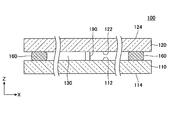
- FIG. 1 shows a schematic cross-sectional view of a first vacuum double-glazed glass that can be produced by the method for producing a vacuum double-glazed glass according to the present invention.
- the first vacuum double-glazed glass 100 includes a first glass substrate 110, a second glass substrate 120, a gap 130 formed between the two glass substrates 110, 120, A plurality of pillars 190 for holding the gap portion 130 and a bonding layer 160 disposed around the first vacuum double-glazed glass 100 are provided.
- the first glass substrate 110 has a first surface 112 and a second surface 114
- the second glass substrate 120 has a first surface 122 and a second surface 124.
- the first glass substrate 110 is disposed such that the second surface 114 side is the outside.
- the 2nd glass substrate 120 is arrange
- the inside of the gap 130 is maintained in a vacuum state.
- the degree of vacuum of the gap 130 is not particularly limited, and may be any pressure lower than atmospheric pressure. In general, the pressure in the gap 130 is about 0.2 Pa to 0.001 Pa.
- the pillar 190 has a role of maintaining the gap 130 in a desired shape. However, the pillar 190 may be omitted when the gap 130 can be maintained in a desired shape without the pillar 190, for example, when the degree of vacuum of the gap 130 is low.
- the bonding layer 160 is annularly arranged around the gap 130 in plan view.
- plan view as used in the present application means a case where the vacuum multilayer glass is viewed in the thickness direction (Z direction in each figure).
- the bonding layer 160 is formed along the periphery of the first vacuum double-glazed glass 100 and functions as a sealing material for maintaining the vacuum of the gap 130.
- the bonding layer 160 may be made of, for example, glass, solder, or a brazing material.
- the bonding layer 160 is shown as a single layer, but the bonding layer 160 may have a two-layer structure.
- a bonding layer having a two-layer structure is, for example, a bonding layer (same type or different type) on each of the first glass substrate 110 and the second glass substrate 120 in the manufacturing process. Or both of the glass substrates 110 and 120 are laminated to form the respective bonding layers.
- FIG. 2 shows a schematic cross-sectional view of a second vacuum double-glazed glass that can be manufactured by the vacuum double-glazed glass manufacturing method according to the present invention.
- the second vacuum double-glazed glass 200 basically includes the same members as the first vacuum double-glazed glass 100 shown in FIG. Therefore, in FIG. 2, the same reference numerals as those in FIG. 1 plus 100 are used for the same members as in FIG.
- the structure of the seal portion is different from that of the first vacuum double-glazing glass 100.
- the second vacuum double-glazed glass 200 has a seal member 250 disposed around the gap portion 230.
- the seal member 250 is formed along the periphery of the second vacuum multilayer glass 200.
- the seal member 250 is configured by laminating a first bonding layer 260, a metal member 255, and a second bonding layer 265 in this order.
- the first bonding layer 260 is annularly disposed on the first surface 212 side of the first glass substrate 210 over the periphery of the first glass substrate 210 in a plan view.
- the second bonding layer 265 is annularly disposed on the first surface 222 side of the second glass substrate 220 over the periphery of the second glass substrate 220 in a plan view.
- the metal member 255 has a first surface 270 and a second surface 272, and has an annular shape in plan view.
- the first surface 270 of the metal member 255 is at least partially bonded to the first bonding layer 260
- the second surface 272 of the metal member 255 is at least partially bonded to the second bonding layer 265. Has been.
- the first surface 270 of the metal member 255 is not bonded to another member at a place other than the bonding portion 275 bonded to the first bonding layer 260.
- the second surface 272 of the metal member 255 is not bonded to other members at positions other than the bonding portion 277 bonded to the second bonding layer 265.
- the metal member 255 has a “step” shape with a contour that is linearly bent when viewed in cross section.
- the shape of the metal member 255 is not particularly limited.
- the metal member 255 may have a curved shape when viewed in cross section, or a contour configured by a combination of a straight line and a curved line.
- the metal member 255 may have a substantially flat shape when viewed in cross section.
- the installation position of the first bonding layer 260 is shifted from the second bonding layer 265 in plan view.
- the first bonding layer 260 may partially or entirely overlap with the second bonding layer 265 when viewed from the Z direction in FIG.
- the sealing member 250 is configured by shifting the installation positions of the first bonding layer 260 and the second bonding layer 265 as in the example of FIG. 2, the first glass substrate 210 and the second glass substrate 220. Even if a temperature difference occurs between the two glass substrates 210 and 220 due to the deformation function in the horizontal direction (X direction in FIG. 2) parallel to the first surface 222 of the second glass substrate 220 of the metal member 255. The advantage of being able to mitigate the effects of differences in thermal expansion between the two is obtained.
- the first and second bonding layers 260 and 265 may be made of, for example, glass, solder, or a brazing material. Further, the first and second bonding layers 260 and 265 may be made of the same material or different materials.
- the gap 230 can be sealed.
- FIG. 3 shows a schematic cross-sectional view of a third vacuum double-glazed glass that can be manufactured by the vacuum double-glazed glass manufacturing method according to the present invention.
- the third vacuum multilayer glass 300 basically includes the same members as the second vacuum multilayer glass 200 shown in FIG. 2. Therefore, in FIG. 3, the same reference numerals as those in FIG. 2 plus 100 are used for the same members as in FIG.
- the structure of the sealing portion is different from that of the second vacuum multilayer glass 200.
- the third vacuum double-glazed glass 300 has the seal member 350 disposed around the gap portion 330.
- the seal member 350 is formed along the periphery of the third vacuum multilayer glass 300.
- the seal member 350 is configured by laminating a first bonding layer 360, a first metal member 355, a third bonding layer 385, a second metal member 380, and a second bonding layer 365 in this order.
- the first bonding layer 360 is installed in a frame shape around the first glass substrate 310 on the first surface 312 side of the first glass substrate 310.
- the second bonding layer 365 is annularly disposed on the first surface 322 side of the second glass substrate 320 over the periphery of the second glass substrate 320 in plan view.
- the first metal member 355 has a first surface 370 and a second surface 372, and has an annular shape in plan view.
- the first surface 370 of the first metal member 355 is at least partially coupled to the first bonding layer 360, and the second surface 372 of the first metal member 355 is at least partially third.
- the bonding layer 385 is bonded.
- the second metal member 380 has a first surface 382 and a second surface 384, and has an annular shape in plan view.
- the first surface 382 of the third metal member 380 is at least partially coupled to the second bonding layer 365, and the second surface 384 of the second metal member 380 is at least partially third.
- the bonding layer 385 is bonded.
- the second metal member 380 has a “step”, and the first surface 382 of the second metal member 380 is a second step when viewed in a cross section of the second metal member 380.
- the profile changes from a height of approximately the same level as the first surface 322 of the glass substrate 320 to a bonding portion of the second bonding layer 365 (hereinafter referred to as “first bonding portion (362a)”).
- first bonding portion (362a) a bonding portion of the second bonding layer 365
- the second metal member 380 may have a substantially flat shape.
- the installation position of the first bonding layer 360 is shifted from the second bonding layer 365 in plan view.
- the first bonding layer 360 may partially or entirely overlap with the second bonding layer 365 when viewed from the Z direction in FIG.
- the horizontal direction parallel to the first surface 322 of the second glass substrate 320 of the second metal member 380 is used. Due to the deformation function in the direction (X direction in FIG. 3), it is possible to mitigate the influence of the difference in thermal expansion between the glass substrates 310 and 320.
- the installation positions of the third bonding layer 385 and the first bonding layer 360 may be shifted, but are preferably installed at the same position as in the example of FIG. By installing in this way, the width of the first metal member 355 can be reduced.
- the first to third bonding layers 360, 365, and 385 may be made of, for example, glass, solder, or brazing material.
- the first to third bonding layers 360, 365, and 385 may be made of the same material or different materials. However, the first and second bonding layers 360 and 365 and the third bonding layer 385 are made of different materials, and the third bonding layer 385 is softer than the first and second bonding layers 360 and 365. It is preferable to be made of a material having a low point. In this case, as will be described later, a first glass portion having a first bonding layer 360 and a first metal member 355, and a second glass portion having a second bonding layer 365 and a second metal member 380. Are prepared in advance, and both glass portions can be bonded via the third bonding layer 385 in the vacuum chamber, so that the manufacturing becomes easier.
- the gap 330 can be sealed.
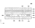
- FIG. 4 shows a schematic cross-sectional view of a fourth vacuum double-glazed glass that can be manufactured by the vacuum double-glazed glass manufacturing method according to the present invention.
- the fourth vacuum multilayer glass 400 basically includes the same members as the first vacuum multilayer glass 100 shown in FIG. 1. Therefore, in FIG. 4, the same reference numerals as those in FIG. 1 are added to the reference numerals of the members in FIG.
- the fourth vacuum multilayer glass 400 is different from the first vacuum multilayer glass 100 in that it further includes a third glass substrate and an intermediate film.
- the third glass substrate 440 is disposed on the opposite side of the second glass substrate 420 from the first glass substrate 410 with the intermediate film 445 interposed therebetween. .
- the type of the intermediate film 445 is not particularly limited, and any conventionally used laminated glass may be used.
- the intermediate film 445 is made of, for example, polyvinyl butyral.
- the gap 430 is sealed by the bonding layer 460 formed along the periphery of the fourth vacuum double-glazed glass 400.
- the gap 430 may be sealed by seal members 250 and 350 as shown in FIGS. 2 and 3 described above.
- sealing layer members that become seal members after the completion of the manufacturing process of the vacuum double-glazed glass are collectively referred to as “sealing layer”.
- first manufacturing method Next, with reference to FIGS. 5 to 9, a method for manufacturing a vacuum double-layer glass according to the first embodiment of the present invention (first manufacturing method) will be described.
- the first manufacturing method will be described by taking as an example the case of manufacturing the vacuum double-layer glass having the structure shown in FIG.
- description of the pillar 190 in FIG. 1 is omitted here.
- a method of installing the pillar 190 a known method well known to those skilled in the art can be applied.
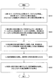
- FIG. 5 schematically shows a flow of the first manufacturing method of the present invention.
- FIGS. 6 to 9 show schematic assembly state diagrams in the respective steps of the first manufacturing method of the present invention.
- the first manufacturing method of the present invention is as follows. (I) preparing a first base glass and a second base glass, and disposing at least two frame-shaped first bonding layers on the first surface of the first base glass ( Step S110) (Ii) The first base glass and the second base glass are laminated so as to face each other through the first bonding layer, and the second base glass is not in contact with the first bonding layer.
- step S120 A step of constructing the assembly in the state (step S120); (Iii) heating the assembly to soften the first bonding layer (step S130); (Iv) After the assembly is placed in a reduced pressure environment, the step of configuring the laminate in a state where the second base glass is in contact with the first bonding layer (step S140); (V) cutting the laminated body so as to separate each first bonding layer to obtain at least two vacuum double-glazed glasses (step S150); Have
- Step S110 First, a first base glass and a second base glass are prepared. Further, at least two frame-shaped bonding layers are formed on the first surface of the first base glass.
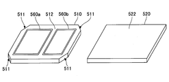
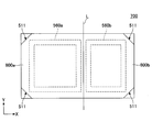
- FIG. 6 shows the first base glass 510 and the second base glass 520.
- the dimensional shape of the first base glass 510 is equivalent to the dimensional shape of the second base glass 520.
- the first base glass 510 may be cut off so that the four corner portions 511 have a substantially triangular shape, for example.
- the dimension of the first base glass 510 may be configured to be slightly smaller than the dimension of the second base glass 520.
- first bonding layer On the first surface 512 of the first base glass 510, a frame-shaped bonding layer 560a and a frame-shaped bonding layer 560b (hereinafter collectively referred to as a “first bonding layer”) are formed. Yes.
- the number of the first bonding layers is two. However, the number is not particularly limited as long as it is plural, and is three, four, five, or more, for example. Also good. Finally, a number of vacuum double glazings according to the number of first bonding layers are produced.
- the first bonding layer 560 a and the bonding layer 560 b are arranged in parallel along the long side of the first base glass 510, but the arrangement mode of both the bonding layers 560 a and 560 b is as follows. Not particularly limited. In particular, when there are three or more first bonding layers, each first bonding layer may be arranged on the first surface 512 of the first base glass 510 in any two-dimensional manner. .
- the first bonding layer 560a and the bonding layer 560b have different dimensional shapes, but the dimensional shapes of both the bonding layers may be substantially the same.
- the second base glass 520 has no bonding layer.
- a plurality of frame-like bonding layers (second bonding layers) similar to those of the first base glass 510 may be formed on the first surface 522 of the second base glass 520.
- the second bonding layer formed on the second base glass 520 is the first base glass when the two base glasses 510 and 520 are laminated so that the first surfaces 512 and 522 face each other.
- the first bonding layers 510 are formed at positions corresponding to the first bonding layers 560a and 560b.
- a vacuum double-glazed glass in which the bonding layer 160 shown in FIG. 1 described above has a two-layer structure is manufactured.
- the first bonding layers 560a and 560b and the second bonding layer are formed of the same material, the boundary between the two layers is unclear.
- the first bonding layers 560a and 560b are not limited thereto, but may be formed of a layer containing glass, solder, brazing material, or the like. .
- first bonding layers 560a and 560b on the first surface 512 of the first base glass 510 will be described by taking as an example the case where the first bonding layers 560a and 560b are vitrified layers. .
- a paste for the glass solidified layer is prepared.
- the paste includes glass frit, ceramic particles, a polymer, an organic binder, and the like.
- the ceramic particles may be omitted.
- the glass frit finally becomes a glass component constituting the vitrified layer.
- the prepared paste is applied in a frame shape to the first surface 512 of the first base glass 510. At this time, the paste is applied so as to obtain at least two frame-shaped portions.
- the first base glass 510 to which the paste is applied is dried.
- the conditions for the drying treatment are not particularly limited as long as the organic binder in the paste is removed.
- the drying process may be performed, for example, by holding the first base glass 510 at a temperature of 100 ° C. to 200 ° C. for about 30 minutes to 1 hour.
- the first base glass 510 is heat-treated at a high temperature.
- the conditions for the heat treatment are not particularly limited as long as the polymer contained in the paste is removed.
- the heat treatment may be performed, for example, by holding the first base glass 510 in a temperature range of 430 ° C. to 470 ° C. for about 30 minutes to 1 hour. As a result, the paste is fired, and a plurality of frame-like vitrified layers are formed.
- Tables 1 and 2 below show, as an example, compositions of glass components contained in the vitrified layer.
- the vitrified layer is made of ZnO—Bi 2 O 3 —B 2 O 3 based glass.
- the vitrified layer is made of ZnO—SnO—P 2 O 5 glass. Vitrified layers having other glass compositions may be obtained.
- Step S120 Next, the first base glass 510 and the second base glass 520 are laminated so as to face each other through the first bonding layers 560a and 560b, thereby forming an assembly.
- the assembly is configured such that the second base glass 520 does not contact the first bonding layers 560a and 560b on the first base glass 510.
- the assembly is similar to the first surface 512 of the first base glass 510 and the second base glass 520.
- the first base glass 510 is configured so as not to contact the second bonding layer on the second base glass 520.
- the assembly is configured later. This is because it is difficult to reduce the gap between the glasses 510 and 520.
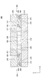
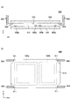
- FIG. 7 schematically shows a configuration example of the formed assembly.
- FIG. 7A is a side view (sectional view) of the assembly
- FIG. 7B is a bottom view of the assembly.
- the assembly 600 is configured by arranging the second base glass 520 on the first base glass 510 with a gap therebetween.
- the assembly 600 further includes a gap forming means 602.
- the gap forming means 602 serves to prevent the second base glass 520 from coming into contact with the first bonding layers 560a and 560b when the second base glass 520 is disposed on the first base glass 510. .
- the gap forming means 602 has a support portion 603 that contacts and supports the first surface 522 of the second base glass 520.
- the support portions 603 of the gap forming means 602 are disposed at four corner portions of the assembly 600 (see FIG. 7B).
- the configuration of the assembly 600 shown in FIG. 7 is merely an example. That is, as long as the second base glass 520 has a configuration that does not come into contact with the first bonding layers 560a and 560b on the first base glass 510 (and the first base glass 510 has a structure on the second base glass 520).
- the assembly may have any configuration (as long as it has a configuration that does not contact the two bonding layers).
- the first base glass 510 and the second base glass 520 may be upside down.
- the first base glass 510 has a shape in which four corner portions 511 are cut into a substantially triangular shape, and the first base glass 510 is disposed when the gap forming means 602 is disposed. 510 does not interfere with the support portion 603 of the gap forming means 602. For this reason, the support portion 603 of the gap forming means 602 can be easily installed.
- the shape processing of the corner portion 511 of the first base glass 510 is not always necessary.
- the size of the first base glass 510 may be selected to be slightly smaller than that of the second base glass 520.
- an assembly 600 in which a gap is formed between the first base glass 510 and the second base glass 520 is formed.
- Step S130 Next, the assembly 600 configured in step S120 is heated. Accordingly, the first bonding layers 560a and 560b are softened. In addition, when the second bonding layer is present, the second bonding layer is also softened.
- the heating temperature varies depending on the type of the first bonding layers 560a and 560b.
- the heating temperature of the assembly 600 may be slightly higher than the softening point of the vitrified layers.
- the heating temperature of the assembly 600 is about 470 ° C. to about 500 ° C. Also good.
- the gap forming means 602 still maintains a state where a gap is secured between the first base glass 510 and the second base glass 520.
- Step S140 Next, the assembly 600 is placed in a vacuum chamber while being heated (i.e., with the first bonding layers 560a and 560b softened) and exposed to a reduced pressure environment.
- the degree of vacuum in the reduced pressure environment is not particularly limited, but the degree of vacuum in the gap 130 of the finally obtained vacuum double-glazed glass 100 increases as the vacuum is increased.
- the degree of vacuum in the reduced pressure environment is, for example, in the range of 1 ⁇ 10 ⁇ 5 Pa to 10 Pa, and preferably 0.1 Pa or less.
- the support portion 603 of the gap forming means 602 is secondly mechanically and / or electrically, or other means.
- the base glass 520 is removed.
- the first base glass 510 and the second base glass 520 are brought into contact with each other through the first bonding layers 560a and 560b to form a laminate.
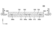
- FIG. 8 shows a schematic cross-sectional view of the laminate 700.
- the gap forming means 602 is moved from the assembly along the horizontal direction (X direction)
- the second base glass 520 falls, and the second base glass 520 becomes the first base glass 520.
- the laminated body 700 is formed in contact with the bonding layers 560a and 560b.
- the first bonding layers 560a and 560b are in a softened state, the first base glass 510 and the second base glass 520 are bonded to each other through the first bonding layers 560a and 560b depending on the structure of the stacked body 700. Is done. As a result, a plurality of gaps 730 are formed between the first base glass 510 and the second base glass 520. Since the gaps 730 are formed under the reduced pressure environment that has continued from the stage of the assembly 600, these gaps 730 are in a vacuum state.
- the laminate 700 is taken out of the vacuum chamber at a high temperature or after the temperature is lowered.
- the first bonding layers 560a and 560b are cooled to room temperature, the first base glass 510 and the second base glass 520 are completely bonded to each other by the first bonding layers 560a and 560b.
- Step S150 Next, the laminated body 700 is cut, and a plurality of vacuum multilayer glasses are separated and formed.
- the multilayer body 700 is cut in the thickness direction along the line L between the bonding layer 560 a and the bonding layer 560 b, thereby forming a vacuum multilayer.
- Glass 800a and vacuum double glazing 800b can be manufactured.
- the cutting means for example, a water jet can be used.
- the first base glass 510 and the second base glass 520 can be cut simultaneously by the water jet.
- each vacuum multilayer glass 800a, 800b three uncut edges are cut at desired positions, and the first bonding layer 560a of the vacuum multilayer glass 800a and the first of the vacuum multilayer glass 800b are cut.
- the position from the end face of one bonding layer 560b may be adjusted to an appropriate dimension.
- two or more vacuum double-glazed glasses can be produced in a single vacuum processing step (step S140).
- step S140 in the first method for producing a vacuum double-glazed glass according to the present invention, two or more vacuum double-glazed glasses can be produced once even if the dimensions and shape of the vacuum double-glazed glass to be produced are different. It can be manufactured in a vacuum processing step (step S140). For this reason, in the 1st manufacturing method of the vacuum double-glazed glass by this invention, improvement of production efficiency and / or suppression of manufacturing cost are attained.
- the first manufacturing method has been described above by taking as an example the case of manufacturing the vacuum double-glazed glass 100 having the structure shown in FIG.
- step S140 when manufacturing the 4th vacuum double-glazed glass 400 as shown in FIG. 4, between step S140 and step S150, (Vi) a step of laminating a third base glass on the laminate 700 through an intermediate film to form a laminated glass assembly (step S160); and (vii) heating and pressurizing the laminated glass assembly.
- step S170 The step of bonding the laminate 700 and the third base glass (step S170) May be added.
- a method known to those skilled in the art as a general laminated glass manufacturing process can be used for these steps S160 and S170. For example, after the laminated glass assembly is heated and temporarily press-bonded, a main press-bonding process in which heat and pressure are applied by an autoclave is performed.
- step 150 the laminated glass assembly after the main press-bonding is cut so as to separate the sealing layers in a plan view, and a plurality of fourth vacuum multilayer glasses 400 shown in FIG. 4 are obtained.
- FIG. 10 schematically shows a flow of the second manufacturing method of the present invention.
- the second manufacturing method of the present invention (I) preparing a first base glass and a second base glass, and disposing at least two frame-shaped first bonding layers on the first surface of the first base glass (steps) S210) (Ii)
- the first base glass and the second base glass are laminated so as to face each other through the first bonding layer, and the second base glass is not in contact with the first bonding layer.
- step S220 A step of constructing the assembly in the state (step S220); (Iii) after the assembly is placed in a reduced pressure environment, the step of forming a laminate in which the second base glass is in contact with the first bonding layer (step S230); (Iv) heating the laminate to soften the bonding layer (step S240); (V) cutting the laminated body so as to separate each first bonding layer to obtain at least two vacuum double-glazed glass (step S250);
- Step S210 and Step S220 respectively have the same steps as Step S110 and Step S120 in the first manufacturing method described above. Therefore, the steps after step S230 will be described here.
- Step S230 For example, the assembly 600 as shown in FIG. 7 is placed in a vacuum chamber, for example, so that the assembly 600 is placed in a reduced pressure environment.
- the degree of vacuum in this reduced pressure environment may be, for example, in the range of 1 ⁇ 10 ⁇ 5 Pa to 10 Pa, and preferably 0.1 Pa or less.
- the space between the first base glass 510 and the second base glass 520 in the assembly 600 is still open by the gap forming means 602. Therefore, by arranging the assembly 600 in a reduced pressure environment, the space between the first base glass 510 and the second base glass 520 can be in a vacuum state.
- the support portion 603 of the gap forming means 602 is removed from the second base glass 520, for example, mechanically and / or electrically, or by other means.
- the first base glass 510 and the second base glass 520 are brought into contact with each other through the first bonding layers 560a and 560b, and the laminated body 700 having the configuration shown in FIG. 8 is formed.
- the gap 730 between the first base glass 520 and the second base glass 520 is blocked from the external environment. However, the space between the first base glass 520 and the second base glass 520 is sufficiently decompressed at the stage of the assembly 600 in the previous stage. For this reason, also in the laminated body 700, the gap
- Step S240 Next, the stacked body 700 is heated to soften the first bonding layers 560a and 560b.
- first base glass 510 and the second base glass 520 are bonded via the first bonding layers 560a and 560b.
- the laminate 700 is taken out of the vacuum chamber at a high temperature or after the temperature is lowered.
- the first bonding layers 560a and 560b are cooled to room temperature, the first base glass 510 and the second base glass 520 are completely bonded to each other by the first bonding layers 560a and 560b.
- Step S250 Thereafter, the stacked body 700 is cut at a predetermined position by the same method as Step S150 in the first manufacturing method. Thereby, a some vacuum multilayer glass can be manufactured.
- the same effect as that in the case of the first production method that is, two or more vacuum multilayer glasses are subjected to one vacuum treatment step ( It is possible to obtain an effect that it can be manufactured in steps S230 to S240. For this reason, also in the 2nd manufacturing method of the vacuum multilayer glass by this invention, improvement in production efficiency and / or suppression of manufacturing cost are attained.
- step S240 and step S250 when manufacturing the 4th vacuum multilayer glass 400 as shown in FIG. 4, between step S240 and step S250, (Vi) laminating a third base glass on the laminate 700 via an intermediate film to form a laminated glass assembly; and (vii) heating and pressurizing the laminated glass assembly, A step of combining 700 and the third base glass may be added.
- FIG. 11 schematically shows a flow of the third manufacturing method of the present invention.
- the third manufacturing method of the present invention (I) preparing a first base glass and a second base glass, and disposing at least two frame-shaped first bonding layers on the first surface of the first base glass ( Step S310) (Ii) The first base glass and the second base glass are laminated so as to face each other through the first bonding layer, and the second base glass is not in contact with the first bonding layer.
- step S320 Configuring the assembly in the state (step S320); (Iii) after placing the assembly in a reduced pressure environment, heating the assembly to soften the first bonding layer (step S330); (Iv) configuring the laminate in a state where the second base glass is in contact with the first bonding layer (step S340); (V) cutting the laminated body so as to separate each first bonding layer to obtain at least two vacuum double-glazed glass (step S350); Have
- Step S310 and Step S320 have the same steps as Step S110 and Step S120 in the first manufacturing method described above, respectively. Therefore, the steps after step S330 will be described here.
- Step S330 For example, the assembly 600 as shown in FIG. 7 is placed in a vacuum chamber, for example, so that the assembly 600 is placed in a reduced pressure environment.
- the degree of vacuum in this reduced pressure environment may be, for example, in the range of 1 ⁇ 10 ⁇ 5 Pa to 10 Pa, and preferably 0.1 Pa or less.
- the space between the first base glass 510 and the second base glass 520 in the assembly 600 is still open by the gap forming means 602. Therefore, by arranging the assembly 600 in a reduced pressure environment, the space between the first base glass 510 and the second base glass 520 can be in a vacuum state.
- the assembly 600 is heated while being placed in a reduced pressure environment, and the first bonding layers 560a and 560b are softened.
- the heating temperature of the assembly 600 is not particularly limited as long as it is a temperature at which the first bonding layers 560a and 560b are softened. As described above, when the first bonding layers 560a and 560b are formed of a vitrified layer, the heating temperature of the assembly 600 may be in the range of about 470 ° C. to about 500 ° C., for example.
- Step S340 Next, in the assembly 600, the support portion 603 of the gap forming means 602 is removed from the second base glass 520, for example, mechanically and / or electrically, or by other means. As a result, the first base glass 510 and the second base glass 520 are brought into contact with each other through the first bonding layers 560a and 560b, and the laminated body 700 having the configuration shown in FIG. 8 is formed.
- the space between the first base glass 520 and the second base glass 520 is blocked from the external environment. Thereby, the gap portion 730 is formed.
- the space between the first base glass 520 and the second base glass 520 is sufficiently decompressed. For this reason, also in the laminated body 700, the gap
- first bonding layers 560a and 560b are in a softened state, the first base glass 510 and the second base glass 520 are interposed through the first bonding layers 560a and 560b depending on the structure of the stacked body 700. Are combined.
- the laminate 700 is taken out of the vacuum chamber at a high temperature or after the temperature is lowered.
- the first bonding layers 560a and 560b are cooled to room temperature, the first base glass 510 and the second base glass 520 are completely bonded to each other by the first bonding layers 560a and 560b.
- Step S350 Thereafter, the stacked body 700 is cut at a predetermined position by the same method as Step S150 in the first manufacturing method. Thereby, a some vacuum multilayer glass can be manufactured.
- the same effect as in the case of the first production method that is, two or more vacuum multilayer glasses are subjected to a single vacuum treatment step (The effect that it can be manufactured in steps S330 to S340) can be obtained.
- the 3rd manufacturing method of the vacuum double layer glass by this invention improvement in production efficiency and / or suppression of manufacturing cost are attained.
- step S340 and step S350 when manufacturing the 4th vacuum multilayer glass 400 as shown in FIG. 4, between step S340 and step S350, (Vi) laminating a third base glass on the laminate 700 via an intermediate film to form a laminated glass assembly; and (vii) heating and pressurizing the laminated glass assembly, A step of combining 700 and the third base glass may be added.
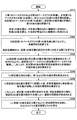
- FIG. 12 schematically shows a flow of the fourth manufacturing method of the present invention.
- FIGS. 13 to 16 show schematic assembly state diagrams in each step of the fourth manufacturing method of the present invention.
- the fourth manufacturing method of the present invention (I) preparing a first base glass and a second base glass, disposing at least two first bonding layers on a first surface of the first base glass; Disposing the same number of second bonding layers as the first bonding layers on the first surface, each first bonding layer being formed in a frame shape with the central portion removed, The second bonding layer is formed in a frame shape with the central portion removed, step (step S410), (Ii) a step of arranging a metal member so as to be in contact with the first bonding layer of the first base glass, wherein the metal member has an opening corresponding to the central portion of each first bonding layer.
- step S420 Having a step (step S420); (Iii) Laminating the first base glass and the second base glass so that the first bonding layer and the second bonding layer are opposed to each other with the metal member interposed therebetween.
- step S430 A step of forming an assembly in which the two bonding layers are not in contact with the metal member
- step S440 heating the assembly to soften the first and second bonding layers
- step S450 After the assembly is placed in a reduced pressure environment, the step of forming a laminate in which the metal member and the second bonding layer are in contact with each other, A step of forming a plurality of gaps by the central part, the opening of the metal member, and the central part of the second bonding layer (step S450); (Vi) cutting the laminated body so as to separate each first bonding layer to obtain at least two vacuum double-glazed glasses (step S460); Have
- Step S410 First, a first base glass and a second base glass are prepared. At least two frame-shaped bonding layers (first bonding layers) are formed on the first surface of the first base glass. Further, the same number of frame-shaped second bonding layers as the first bonding layers are formed on the first surface of the second base glass. As will be described later, the second bonding layer is disposed at a position “corresponding” to the first bonding layer.
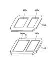
- FIG. 13 shows the first base glass and the second base glass.
- the first base glass 910 has a first surface 912, and two first bonding layers 960 a and 960 b are provided on the first surface 912.
- the second base glass 920 has a first surface 922, and two second bonding layers 961 a and 961 b are provided on the first surface 922.
- the first bonding layers 960a and 960b and the second bonding layers 961a and 961b may be formed of, for example, a glass solidified layer as described above.
- the dimensional shape of the first base glass 910 may be substantially the same as the dimensional shape of the second base glass 920.
- the first base glass 910 is cut out so that the four corner portions 911 have a substantially triangular shape.
- this shape is not always necessary.
- the second bonding layer 961a installed on the second base glass 920 is installed on the first base glass 910 when the first base glass 910 and the second base glass 920 are laminated in the subsequent steps.
- the first bonding layer 960a is disposed at a “corresponding” position.
- the second bonding layer 961b installed on the second base glass 920 is formed when the first base glass 910 and the second base glass 920 are laminated in the subsequent steps. It is disposed at a position “corresponding” to the first bonding layer 960 b installed in 910.
- corresponding position of two members is a positional relationship in which the structure portion functions properly when the structure portion including the two members is formed. This means a state where they are arranged.
- a position where two members “correspond” includes a state in which both members overlap each other when a structure including the two members is formed.
- the first bonding layer 960a and the second bonding layer 961a are formed when a laminated body is formed in the subsequent step S450 or when a vacuum double-layer glass is finally manufactured. These are disposed on the respective base glasses 910 and 920 in such a positional relationship that an appropriate seal structure is formed. Similarly, the first bonding layer 960b and the second bonding layer 961b are properly sealed when the laminated body is formed in the subsequent step S450 or when the vacuum double-layer glass is finally manufactured. They are arranged on the respective base glasses 910 and 920 in such a positional relationship that the structure is formed.
- first bonding layers and two second bonding layers are formed, but the number of first bonding layers and second bonding layers is three or more, respectively. It may be. The number of first and second bonding layers determines the number of vacuum double glazing that is finally produced.
- Step S420 a metal member is disposed on the first base glass 910 so as to be in contact with the first bonding layers 960 a and 960 b of the first base glass 910.
- the material of the metal member may be, for example, aluminum metal or alloy, titanium metal or alloy, copper metal or alloy, or stainless steel.
- the metal member is plate-shaped or foil-shaped, and may have a thickness in the range of 5 ⁇ m to 500 ⁇ m.
- FIG. 14 shows a state in which a metal member is arranged on the first base glass 910.
- the metal member 955 has an outer dimension and shape substantially the same as those of the first base glass 910.
- the metal member 955 has an opening 957a corresponding to the first bonding layer 960a and an opening 957b corresponding to the first bonding layer 960b. Therefore, the metal member 955 can be used as a frame-shaped metal member 255 constituting the seal structure 250 as shown in FIG. 2 when the vacuum double-glazed glass is finally manufactured.
- the metal member 955 may be temporarily fixed to the first bonding layers 960a and 960b.
- the metal member 955 is provided as a single integrated part.
- a plurality of frame-shaped metal members corresponding to the first bonding layers 960a and 960b may be prepared and disposed on the first bonding layers 960a and 960b.
- the placement of the metal member is completed by a single placement operation, so that the placement of the metal member on the first base glass 910 becomes easy. .
- the metal member 955 is disposed on the first bonding layers 960a and 960b of the first base glass 910.
- Step S430 Next, the first base glass 910 and the second base glass 920 are laminated so that the first bonding layers 960a and 960b and the second bonding layers 961a and 961b face each other with the metal member 955 interposed therebetween. An assembly is configured.
- the second base glass 920 is disposed on the first base glass 910 so that the second bonding layers 961a and 961b do not come into contact with the metal member 955.
- FIG. 15 schematically shows a configuration example of the assembly.
- FIG. 15A is a cross-sectional view of the assembly
- FIG. 15B is a bottom view of the assembly.
- the second bonding layers 961a and 961b are omitted for clarity.
- the assembly 1000 is configured by disposing a second base glass 920 with a gap on top of the first base glass 910 on which the metal member 955 is installed.
- the assembly 1000 also includes the gap forming means 602 described above.
- the gap forming means 602 makes it possible to dispose the second base glass 920 on the first base glass 910 such that the second bonding layers 961a and 961b do not come into contact with the metal member 955.
- the gap forming means 602 has a support portion 603 that contacts and supports the first surface 922 of the second base glass 920. Support portions 603 of the gap forming means 602 are arranged at four corner portions of the assembly 1000 (see FIG. 15B).
- the corresponding first bonding layer and second bonding layer (for example, the first bonding layer 960 a and the second bonding layer 961 a, and the first bonding layer 960 b and the second bonding layer).
- the layers 961b) are arranged so that they do not overlap each other when the assembly 1000 is viewed from the thickness direction.
- the corresponding first bonding layer and second bonding layer may partially or entirely overlap.
- the seal structure having the thermal stress relaxation capability in the vacuum multilayer glass finally manufactured. Is obtained.
- the first base glass 910 and the metal member 955 have a shape in which four corner portions are cut into a substantially triangular shape, and the first base glass 910 and the metal member 955 have the first shape when the gap forming means 602 is disposed.
- the base glass 910 and the metal member 955 do not interfere with the support portion 603 of the gap forming means 602.
- shape processing of the corner portions of the first base glass 910 and the metal member 955 is not necessarily required.
- the dimensions of the first base glass 910 and the metal member 955 may be selected to be slightly smaller than those of the second base glass 920.
- the assembly 1000 in which a gap is formed between the first base glass 910 and the second base glass 920 is configured.
- Step S440 Next, the assembly 1000 configured in step S430 is heated. Accordingly, the first bonding layers 960a and 960b and the second bonding layers 961a and 961b are softened.
- the heating temperature may be, for example, about 470 ° C. to about 500 ° C. when the first bonding layers 960a and 960b and the second bonding layers 961a and 961b are lath solidified layers.
- the gap forming means 602 still maintains an open space between the metal member 955 and the second base glass 920.
- Step S450 Next, the assembly 1000 is placed in a heated chamber, for example, in a vacuum chamber and exposed to a reduced pressure environment.
- the degree of vacuum in this reduced pressure environment is, for example, in the range of 1 ⁇ 10 ⁇ 5 Pa to 10 Pa, and preferably 0.1 Pa or less.
- the support portion 603 of the gap forming means 602 is moved to the second portion in the assembly 1000, for example, mechanically and / or electrically, or by other means.
- the base glass 920 is removed.
- the first base glass 910 and the second base glass 920 are brought into contact with each other via the first bonding layers 960a and 960b, the metal member 955, and the second bonding layers 961a and 961b, thereby forming a laminated body.
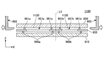
- FIG. 16 shows a schematic cross-sectional view of the obtained laminated body 1100.
- the gap forming means 602 is moved from the assembly along the horizontal direction (X direction)
- the second base glass 920 falls, and the second base glass 920 is moved to the second position.
- the bonding layers 961a and 961b are in contact with the metal member 955, and the laminate 1100 is formed.
- the metal member 955 may be deformed from a flat cross-sectional shape to a cross-sectional shape having a step by pressurization due to the fall of the second base glass 920.
- the first base glass 910 and the second base glass 920 are made of metal depending on the structure of the stack 1100. Coupled via member 955.
- the metal member 955 has an opening 957a corresponding to the first bonding layer 960a and the second bonding layer 961a, and an opening 957b corresponding to the first bonding layer 960b and the second bonding layer 961b, respectively.
- the second bonding layers 961a and 961b are disposed at positions corresponding to the first bonding layers 960a and 960b, respectively.
- a plurality of gaps 1130 are formed between the first base glass 910 and the second base glass 920. Since these gaps 1130 are formed in a reduced pressure environment that continues from the stage of the assembly 1000, these gaps 1130 are in a vacuum state.
- the laminate 1100 is taken out of the vacuum chamber at a high temperature or after the temperature is lowered.
- the first bonding layers 960a and 960b and the second bonding layers 961a and 961b are cooled to room temperature, the first base glass 910 and the second base glass 920 are metal members by the bonding layers. Fully coupled via 955.
- Step S460 Next, the laminated body 1100 is cut, and a plurality of vacuum multilayer glasses are separated and formed.
- two vacuum double glazings can be manufactured by cutting the laminated body 1100 in the thickness direction at the position of the broken line L2.
- a plurality of the vacuum double glazing 200 having the seal structure 250 as shown in FIG. 2 is manufactured by the fourth manufacturing method.
- the fourth manufacturing method can provide the same effects as those of the first to third manufacturing methods described above.
- the assembly 1000 is heated in the atmospheric environment in step S440 and then placed in a reduced pressure environment in step S450.
- a laminate is formed under this reduced pressure environment.
- the assembly 1000 is placed in a reduced pressure environment at room temperature as in the above-described second manufacturing method, and is formed into a laminated body here (see step S230). It may be heated (see step S240).
- the assembly 1000 may be placed in a reduced-pressure environment at room temperature and heated (see step S330) as in the above-described third manufacturing method, and then a laminated body may be configured. Good (see step S340).
- a vacuum multilayer glass manufacturing method (fifth manufacturing method) according to a fifth embodiment of the present invention.
- the fifth manufacturing method will be described by taking as an example the case of manufacturing the vacuum double-layer glass having the structure shown in FIG.
- the description of the pillar 390 in FIG. 3 is also omitted here.
- FIG. 17 schematically shows a flow of the fifth manufacturing method of the present invention.
- 18 to 22 show schematic assembly state diagrams in each step of the fifth manufacturing method of the present invention.
- the fifth manufacturing method of the present invention (I) preparing a first base glass and a second base glass, disposing at least two first bonding layers on a first surface of the first base glass; Disposing the same number of second bonding layers as the first bonding layers on the first surface, each first bonding layer being formed in a frame shape with the central portion removed, The second bonding layer is formed in a frame shape with the central portion removed (step S510); (Ii) The first metal member is disposed so as to be in contact with the first bonding layer of the first base glass, and the second metal is disposed so as to be in contact with the second bonding layer of the second base glass.
- step S520 Disposing a member, wherein the first metal member has a first opening corresponding to the central portion of each first bonding layer, and the second metal member includes each second A second opening corresponding to the central portion of the bonding layer (step S520); (Iii) disposing a third bonding layer having an opening corresponding to each first opening of the first metal member on the first metal member (step S530); (Iv) laminating the first base glass and the second base glass so that the first metal member and the second metal member face each other via the third bonding layer, thereby A step (step S540) of forming an assembly in which the third bonding layer is in non-contact with the second metal member; (V) heating the assembly to soften the third bonding layer (step S550); (Vi) a step of configuring a laminated body in a state where the second metal member and the third bonding layer are in contact with each other after the assembly is placed in a reduced pressure environment, whereby the first metal member The central portion of the bonding layer, the first opening of the
- Step S510 First, a first base glass and a second base glass are prepared. At least two frame-shaped first bonding layers are formed on the first surface of the first base glass. Further, the same number of frame-shaped second bonding layers as the first bonding layers are formed on the first surface of the second base glass. As will be described later, the second bonding layer is disposed at a position corresponding to the first bonding layer.
- FIG. 18 shows the first base glass and the second base glass.
- the first base glass 1210 has a first surface 1212, and two first bonding layers 1260 a and 1260 b are installed on the first surface 1212.
- the second base glass 1220 has a first surface 1222, and two second bonding layers 1261 a and 1261 b are provided on the first surface 1222.
- the first bonding layers 1260a and 1260b and the second bonding layers 1261a and 1261b may be formed of, for example, a glass solidified layer as described above.
- the dimensional shape of the first base glass 1210 may be substantially the same as the dimensional shape of the second base glass 1220. Although not shown in FIG. 18, as described above, the first base glass 1210 may be cut out so that the four corner portions have a substantially triangular shape.
- the second bonding layer 1261a installed on the second base glass 1220 is installed on the first base glass 1210 when the first base glass 1210 and the second base glass 1220 are laminated in the subsequent steps.
- the first bonding layer 1260a is disposed at a position “corresponding”.
- the second bonding layer 1261b installed on the second base glass 1220 is formed when the first base glass 1210 and the second base glass 1220 are laminated in the subsequent steps.
- the first bonding layer 1260b provided at 1210 is disposed at a “corresponding” position.
- Step S520 a first metal member is disposed on the first base glass 1210 so as to be in contact with the first bonding layers 1260a and 1260b of the first base glass 1210.
- the second metal member is disposed on the second base glass 1220 so as to be in contact with the second bonding layers 1261a and 1261b of the second base glass 1220.
- the material of the first and second metal members may be, for example, aluminum metal or alloy, titanium metal or alloy, copper metal or alloy, or stainless steel.
- the first and second metal members are plate-shaped or foil-shaped, and may have a thickness in the range of 5 ⁇ m to 500 ⁇ m.
- first and second metal members may be made of the same material or different materials.
- the first and second metal members may have the same dimensional shape or different dimensional shapes.
- the left diagram of FIG. 19 shows a state in which the first metal member 1255 is disposed on the first base glass 1210. Further, the right side of FIG. 19 shows a state in which the second metal member 1280 is disposed on the second base glass 1220.
- the first metal member 1255 has substantially the same outer dimensions and shape as the first base glass 1210.
- the first metal member 1255 has a first opening 1257a corresponding to the first bonding layer 1260a and a first opening 1257b corresponding to the first bonding layer 1260b. Therefore, the first metal member 1255 is used as the frame-shaped first metal member 355 constituting the seal structure 350 as shown in FIG. 3 when the vacuum double-layer glass is finally manufactured. can do.
- the first metal member 1255 is provided as a single integrated part.
- a plurality of frame-shaped metal members corresponding to the first bonding layers 1260a and 1260b may be prepared and disposed on the first bonding layers 1260a and 1260b.
- the placement of the metal member is completed by a single placement operation, so the first metal member 1255 is placed on the first base glass 1210. Becomes easy.
- the second metal member 1280 arranged on the second base glass 1220 includes a second opening 1281a corresponding to the second bonding layer 1261a and a second opening corresponding to the second bonding layer 1261b. 1281b. Therefore, the second metal member 1280 is used as the frame-shaped second metal member 380 constituting the seal structure 350 shown in FIG. 3 when the vacuum double-glazed glass is finally manufactured. can do.
- first bonding layer 1260a, 1260b and the first metal member 1255 are installed on the first surface 1212 of the first base glass 1210 (hereinafter referred to as “first preliminary assembly”).
- first preliminary assembly Solid "1200A) is manufactured.
- second preliminary assembly a member in which the second bonding layers 1261a and 1261b and the second metal member 1280 are installed on the first surface 1222 of the second base glass 1220 (hereinafter referred to as “second preliminary assembly”). 1200B) is manufactured.
- the first preliminary assembly 1200A is fired.
- the first metal member 1255 and the first base glass 1210 may be bonded to each other through the first bonding layers 1260a and 1260b. The same can be said for the second preliminary assembly 1200B.
- a third bonding layer is disposed on the first metal member 1255 of the first preliminary assembly 1200A.
- the third bonding layer has openings corresponding to the first openings 1257 a and 1257 b of the first metal member 1255.
- FIG. 20 schematically shows a cross section of a first preliminary assembly 1200A having a third bonding layer formed thereon.
- the third bonding layer 1285 is disposed along the shape of the first metal member 1255 immediately below so as not to block the first openings 1257a and 1257b.
- the third bonding layer 1285 may be integrally formed as a single layer having two openings, or may be configured as a plurality of separate and independent layers. In the latter case, each third bonding layer 1285 is formed in a frame shape around the respective first openings 1257 a and 1257 b of the first metal member 1255.
- the third bonding layer 1285 may be composed of a layer containing glass, solder, brazing material, or the like, for example.
- the third bonding layer 1285 is preferably made of a material having a lower softening point than the first and second bonding layers 1260a, 1260b, 1261a, and 1261b.
- the first and second bonding layers 1260a, 1260b, 1261a, and 1261b are not changed, and only the third bonding layer 1285 is softened, and the first metal member 1255 is softened.
- the second metal member 1280 can be combined.
- the third bonding layer 1285 is made of a material having a softening point lower than those of the first bonding layers 1260a and 1260b and the second bonding layers 1261a and 1261b. To do.
- Step S540 Next, the first preliminary assembly 1200 ⁇ / b> A and the second preliminary assembly 1200 ⁇ / b> B manufactured through the above steps are stacked via the third bonding layer 1285 to form an assembly.
- the second pre-assembly 1200B is arranged so that the second pre-assembly 1200B (the second metal member 1280 thereof) does not come into contact with the third bonding layer 1285. It is arranged on the preliminary assembly 1200A.
- FIG. 21 schematically shows a configuration example of the assembly.
- the assembly 1300 is configured by disposing a second preliminary assembly 1200B with a space above the first preliminary assembly 1200A.
- the first preliminary assembly 1200A and the second preliminary assembly 1200B are arranged such that the respective metal members 1255 and 1280 face each other.
- the assembly 1300 further includes the gap forming means 602 described above.
- the second preliminary assembly 1200B can be arranged on the first preliminary assembly 1200A so as not to contact the third bonding layer 1285 by the gap forming means 602.
- the gap forming means 602 has a support portion 603 that contacts and supports the second metal member 1280 of the second preliminary assembly 1200B. As described above, the support portions 603 of the gap forming means 602 may be disposed at the four corner portions of the assembly 1300.
- the support portion 603 of the gap forming means 602 may support the second preliminary assembly 1200B with the first surface 1222 of the second base glass 1220.
- the end portion of the second metal member 1280 may be terminated inside the second base glass 1220.
- the corresponding first bonding layer and second bonding layer (for example, the first bonding layer 1260a and the second bonding layer 1261a, and the first bonding layer 1260b and the second bonding layer).
- the layers 1261b) are arranged so that they do not overlap each other when the assembly 1300 is viewed from the thickness direction.
- the corresponding first bonding layer and second bonding layer may partially or entirely overlap.
- the seal structure having the thermal stress relaxation ability Is obtained obtained.
- an assembly 1300 is formed in which an open space is formed between the first preliminary assembly 1200A and the second preliminary assembly 1200B.
- Step S550 Next, the assembly 1300 configured in step S540 is heated. Accordingly, the third bonding layer 1285 is softened.
- the heating temperature may be about 250 ° C. to about 350 ° C. when the third bonding layer 1285 is made of a solder material, for example.
- the gap forming means 602 still maintains an open space between the first preliminary assembly 1200A and the second preliminary assembly 1200B.
- Step S560 Next, the assembly 1300 is placed in a heated state, for example, in a vacuum chamber and exposed to a reduced pressure environment.
- the degree of vacuum in this reduced pressure environment is, for example, in the range of 1 ⁇ 10 ⁇ 5 Pa to 10 Pa, and preferably 0.1 Pa or less.
- the support portion 603 of the gap forming means 602 is mechanically and / or electrically, or other means, for example. It is removed from the pre-assembly 1200B. As a result, the first preliminary assembly 1200A and the second preliminary assembly 1200B are brought into contact with each other via the third bonding layer 1285, thereby forming a stacked body.
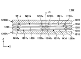
- FIG. 22 shows a schematic cross-sectional view of the obtained laminate 1400.
- the second preliminary assembly 1200B is dropped by moving the gap forming means 602 from the assembly 1300 along the horizontal direction (X direction).
- the second metal member 1280 of the second pre-assembly 1200B and the first metal member 1255 of the first pre-assembly 1200A are in contact with the third bonding layer 1285, and the laminate 1400 Is configured.
- the second metal member 1280 may be deformed from a flat cross-sectional shape to a cross-sectional shape having a step by pressurization due to the fall of the second pre-assembly 1200B.
- the third bonding layer is in a softened state, the first preliminary assembly 1200 ⁇ / b> A and the second preliminary assembly 1200 ⁇ / b> B are bonded via the third bonding layer 1285 according to the configuration of the stacked body 1400. .
- the first metal member 1255 is formed in the first opening 1257a corresponding to the first bonding layer 1260a and the second bonding layer 1261a, and the first bonding layer 1260b and the second bonding layer 1261b, respectively.
- a corresponding first opening 1257b is provided.
- the second metal member 1280 is formed in the second opening 1281a corresponding to the first bonding layer 1260a and the second bonding layer 1261a, and the first bonding layer 1260b and the second bonding layer 1261b, respectively.
- a corresponding second opening 1281b is provided.
- the third bonding layer 1285 has openings corresponding to the first openings 1257a and 1257b of the first metal member 1255.
- gaps 1430 are formed between the first base glass 1210 and the second base glass 1220. Since these gaps 1430 are formed in a reduced pressure environment that continues from the stage of the assembly 1300, the gaps 1430 are in a vacuum state.
- the laminated body 1400 is taken out of the vacuum chamber at a high temperature or after the temperature is lowered.
- the third bonding layer 1285 is cooled to room temperature, the first pre-assembly 1200A and the second pre-assembly 1200B are completely bonded via the third bonding layer 1285.
- Step S570 Next, the laminated body 1400 is cut, and a plurality of vacuum multilayer glasses are separated and formed.
- two vacuum double glazings can be manufactured by cutting the laminated body 1400 in the thickness direction at the position of the broken line L3.
- a plurality of vacuum double-glazed glasses 300 having the seal structure 350 as shown in FIG. 3 are manufactured by the fifth manufacturing method.
- the fifth manufacturing method can provide the same effects as those of the first to third manufacturing methods described above.
- the assembly 1300 is heated in the atmospheric environment in step S550 and then placed in a reduced pressure environment in step S560.
- a laminate is formed under this reduced pressure environment.
- the assembly 1300 is placed in a reduced pressure environment at room temperature as in the above-described second manufacturing method, and is formed into a laminated body here (see step S230). It may be heated (see step S240).
- the assembly 1300 may be placed in a reduced-pressure environment at room temperature and heated (see step S330) as in the above-described third manufacturing method, and then a laminated body may be configured. Good (see step S340).
- the first bonding layer, the second bonding layer, and the third bonding layer may be made of the same material.
- step S550 described above since the first and second bonding layers are softened in addition to the third bonding layer, the relative positions of the respective members constituting the sealing member may change. However, often such flexibility is required in the manufacture of vacuum double glazing.
- the present invention can be used for vacuum double glazing and the like used for window glass of buildings.
Landscapes
- Engineering & Computer Science (AREA)
- Chemical & Material Sciences (AREA)
- Civil Engineering (AREA)
- Structural Engineering (AREA)
- Chemical Kinetics & Catalysis (AREA)
- Life Sciences & Earth Sciences (AREA)
- Ceramic Engineering (AREA)
- General Chemical & Material Sciences (AREA)
- Geochemistry & Mineralogy (AREA)
- Materials Engineering (AREA)
- Organic Chemistry (AREA)
- Joining Of Glass To Other Materials (AREA)
- Securing Of Glass Panes Or The Like (AREA)
Abstract
本発明による真空複層ガラスの製造方法は、第1の表面を有する第1のベースガラスを含む第1の予備組立体、および第1の表面を有する第2のベースガラスを含む第2の予備組立体を構成するステップであって、前記第1のベースガラスの第1の表面には、平面視で環状の複数の封着層が形成されるステップと、前記第1のベースガラスの第1の表面と前記第2のベースガラスの第1の表面とが互いに対向するように、かつ前記封着層が前記第2の予備組立体と非接触の状態で前記第1の予備組立体と前記第2の予備組立体とを積層し、組立体を構成するステップと、前記組立体を減圧環境下に配置した後、前記第2の予備組立体と前記封着層とを接触させ、積層体を構成するステップと、平面視で各封着層を分離するように前記積層体を切断するステップと、を有する。
Description
本発明は、真空複層ガラスの製造方法に関する。
一対のガラス基板を間隙部を介して積層し、該間隙部を低圧または真空状態に保持して構成される、いわゆる「真空複層ガラス」は、優れた断熱効果を有するため、例えばビルおよび住宅等の建築物用の窓ガラス用途に広く利用されている。
そのような真空複層ガラスは、一般に、
-2枚のガラス基板を準備し、ガラス基板の少なくとも一方の表面の周縁に、ガラスフリットを設置する工程(ガラスフリット設置工程)、
-ガラスフリットを挟んで2枚のガラス基板を積層して間隙部を構成した後、ガラスフリットを加熱して軟化させ、該ガラスフリットを介して、2枚のガラス基板を結合させる工程(封止工程)、および
-一方のガラス基板に設けられた排気口を利用して間隙部を減圧状態とした後、この排気口を封止する工程(真空引き工程)、
等を実施することにより製造される。
-2枚のガラス基板を準備し、ガラス基板の少なくとも一方の表面の周縁に、ガラスフリットを設置する工程(ガラスフリット設置工程)、
-ガラスフリットを挟んで2枚のガラス基板を積層して間隙部を構成した後、ガラスフリットを加熱して軟化させ、該ガラスフリットを介して、2枚のガラス基板を結合させる工程(封止工程)、および
-一方のガラス基板に設けられた排気口を利用して間隙部を減圧状態とした後、この排気口を封止する工程(真空引き工程)、
等を実施することにより製造される。
例えば、ビルおよび住宅等の建築物には、各種寸法形状の窓ガラスが使用される。そのような設置場所の要求仕様に対応させるため、真空複層ガラスも、各種寸法および/または形状のものが必要となる。
このような各種寸法形状の真空複層ガラスに対するニーズに対応するため、これまで、真空複層ガラスは、いわば「一品生産式」に製造されており、すなわち、一つの真空複層ガラスの製造の度に、前述の各工程が実施されている。
しかしながら、このような真空複層ガラスの製造方法では、生産効率の向上を図ることが難しいという問題がある。
本発明は、このような背景に鑑みなされたものであり、本発明では、生産効率の高い真空複層ガラスの製造方法を提供することを目的とする。
本発明では、2枚のガラス基板が間隙部を介して積層された真空複層ガラスの製造方法であって、
(a)第1の表面を有する第1のベースガラスを含む第1の予備組立体、および第1の表面を有する第2のベースガラスを含む第2の予備組立体を構成するステップであって、前記第1のベースガラスの第1の表面には、平面視で環状を有しかつ環状に囲まれる領域が互いに重複しない複数の封着層が形成されるステップと、
(b)前記第1のベースガラスの第1の表面と前記第2のベースガラスの第1の表面とが互いに対向するように、かつ前記封着層が前記第2の予備組立体と非接触の状態で前記第1の予備組立体と前記第2の予備組立体とを積層し、組立体を構成するステップと、
(c)前記組立体を減圧環境下に配置した後、該減圧環境下において前記第2の予備組立体と前記封着層とを接触させ、前記第1の予備組立体と前記第2の予備組立体とが接合した積層体を構成するステップと、
(d)平面視で各封着層を分離するように前記積層体を切断し、複数の真空複層ガラスを得るステップと、
を有することを特徴とする真空複層ガラスの製造方法が提供される。
(a)第1の表面を有する第1のベースガラスを含む第1の予備組立体、および第1の表面を有する第2のベースガラスを含む第2の予備組立体を構成するステップであって、前記第1のベースガラスの第1の表面には、平面視で環状を有しかつ環状に囲まれる領域が互いに重複しない複数の封着層が形成されるステップと、
(b)前記第1のベースガラスの第1の表面と前記第2のベースガラスの第1の表面とが互いに対向するように、かつ前記封着層が前記第2の予備組立体と非接触の状態で前記第1の予備組立体と前記第2の予備組立体とを積層し、組立体を構成するステップと、
(c)前記組立体を減圧環境下に配置した後、該減圧環境下において前記第2の予備組立体と前記封着層とを接触させ、前記第1の予備組立体と前記第2の予備組立体とが接合した積層体を構成するステップと、
(d)平面視で各封着層を分離するように前記積層体を切断し、複数の真空複層ガラスを得るステップと、
を有することを特徴とする真空複層ガラスの製造方法が提供される。
ここで、本発明による製造方法は、
前記(c)のステップと前記(d)のステップの間に、
(e)前記積層体に中間膜を介して第3のベースガラスを積層して、合わせガラス組立体を構成するステップと、
(f)前記合わせガラス組立体を加熱、加圧して、前記積層体と第3のベースガラスを結合するステップと、
を有しても良い。
前記(c)のステップと前記(d)のステップの間に、
(e)前記積層体に中間膜を介して第3のベースガラスを積層して、合わせガラス組立体を構成するステップと、
(f)前記合わせガラス組立体を加熱、加圧して、前記積層体と第3のベースガラスを結合するステップと、
を有しても良い。
また、本発明による製造方法において、前記封着層はガラス固化層で構成され、
前記(c)のステップは、前記組立体を減圧環境下に配置する前または後に前記ガラス固化層を加熱するステップを有し、
その後、軟化した前記ガラス固化層を介して、前記第1の予備組立体と前記第2の予備組立体とが接触してから、前記ガラス固化層が冷却固化され、前記第1の予備組立体と前記第2の予備組立体とが接合されても良い。
前記(c)のステップは、前記組立体を減圧環境下に配置する前または後に前記ガラス固化層を加熱するステップを有し、
その後、軟化した前記ガラス固化層を介して、前記第1の予備組立体と前記第2の予備組立体とが接触してから、前記ガラス固化層が冷却固化され、前記第1の予備組立体と前記第2の予備組立体とが接合されても良い。
あるいは、本発明による製造方法では、前記(a)のステップにおいて、前記第2のベースガラスの第1の表面には、平面視で環状を有しかつ環状に囲まれる領域が互いに重複しない複数の第2の封着層が形成され、
前記第1の予備組立体の第1の表面に形成される前記封着層は、前記第1のベースガラスの第1の表面に、平面視で環状の複数の第1の接合層を形成した後、それぞれの第1の接合層の上に平面視で環状の第1の金属部材を接合することにより構成され、
前記第2の予備組立体の第1の表面に形成される前記第2の封着層は、前記第2のベースガラスの第1の表面に、前記第1の接合層に対応した同数の、平面視で環状の第2の接合層を形成することにより構成され、
前記(c)のステップは、前記組立体を減圧環境下に配置する前または後に前記第2の接合層を加熱するステップを有し、
その後、軟化した前記第2の接合層を介して、前記第1の金属部材と前記第2の予備組立体とが接触してから、前記第2の接合層が冷却固化され、前記第1の予備組立体と前記第2の予備組立体とが接合されても良い。
前記第1の予備組立体の第1の表面に形成される前記封着層は、前記第1のベースガラスの第1の表面に、平面視で環状の複数の第1の接合層を形成した後、それぞれの第1の接合層の上に平面視で環状の第1の金属部材を接合することにより構成され、
前記第2の予備組立体の第1の表面に形成される前記第2の封着層は、前記第2のベースガラスの第1の表面に、前記第1の接合層に対応した同数の、平面視で環状の第2の接合層を形成することにより構成され、
前記(c)のステップは、前記組立体を減圧環境下に配置する前または後に前記第2の接合層を加熱するステップを有し、
その後、軟化した前記第2の接合層を介して、前記第1の金属部材と前記第2の予備組立体とが接触してから、前記第2の接合層が冷却固化され、前記第1の予備組立体と前記第2の予備組立体とが接合されても良い。
あるいは、本発明による製造方法では、前記(a)のステップにおいて、前記第2のベースガラスの第1の表面には、平面視で環状を有しかつ環状に囲まれる領域が互いに重複しない複数の第2の封着層が形成され、
前記(a)のステップにおいて、前記第1の予備組立体に形成される封着層は、前記第1のベースガラスの第1の表面に、平面視で環状の複数の第1の接合層を形成し、それぞれの第1の接合層の上に平面視で環状の第1の金属部材を接合し、前記第1の金属部材のそれぞれの上に、平面視で環状の第3の接合層を形成することにより構成され、
前記第2の予備組立体の第1の表面に形成される前記第2の封着層は、前記第2のベースガラスの第1の表面に、前記第1の接合層に対応した同数の、平面視で環状の第2の接合層を形成し、さらにそれぞれの第2の接合層の上に、平面視で環状の第2の金属部材を接合することにより構成され、
前記(c)のステップは、前記組立体を減圧環境下に配置する前または後に前記第3の接合層を加熱するステップを有し、
その後、軟化した第3の接合層は、前記第2の金属部材と接触されてから冷却固化され、前記第1の予備組立体と前記第2の予備組立体とが接合されても良い。
前記(a)のステップにおいて、前記第1の予備組立体に形成される封着層は、前記第1のベースガラスの第1の表面に、平面視で環状の複数の第1の接合層を形成し、それぞれの第1の接合層の上に平面視で環状の第1の金属部材を接合し、前記第1の金属部材のそれぞれの上に、平面視で環状の第3の接合層を形成することにより構成され、
前記第2の予備組立体の第1の表面に形成される前記第2の封着層は、前記第2のベースガラスの第1の表面に、前記第1の接合層に対応した同数の、平面視で環状の第2の接合層を形成し、さらにそれぞれの第2の接合層の上に、平面視で環状の第2の金属部材を接合することにより構成され、
前記(c)のステップは、前記組立体を減圧環境下に配置する前または後に前記第3の接合層を加熱するステップを有し、
その後、軟化した第3の接合層は、前記第2の金属部材と接触されてから冷却固化され、前記第1の予備組立体と前記第2の予備組立体とが接合されても良い。
この場合、前記第3の接合層は、前記第1および第2の接合層よりも低い軟化点を有する材料で構成されても良い。
また、本発明による製造方法において、前記第1の金属部材は、単一の板または箔で構成されても良い。
また、本発明による製造方法では、前記(c)のステップで得られる前記積層体において、各第2の接合層は、平面視で、対応する各第1の接合層とは位置がずれていても良い。
また、本発明による製造方法において、前記第1の接合層および/または第2の接合層は、ガラス固化層を有しても良い。
また、本発明による製造方法では、前記(b)のステップにおける前記組立体において、前記第2の予備組立体は、4つのコーナー部を支持する手段によって、前記第1の予備組立体と非接触の状態とされても良い。
本発明では、生産効率の高い真空複層ガラスの製造方法を提供することができる。
以下、本発明の実施形態について説明する。
まず、図面を参照して、本発明による真空複層ガラスの製造方法によって製造され得る、いくつかの真空複層ガラスの構成例について説明する。
(第1の真空複層ガラスの構成)
図1には、本発明による真空複層ガラスの製造方法によって製造され得る第1の真空複層ガラスの概略的な断面図を示す。
図1には、本発明による真空複層ガラスの製造方法によって製造され得る第1の真空複層ガラスの概略的な断面図を示す。
図1に示すように、第1の真空複層ガラス100は、第1のガラス基板110と、第2のガラス基板120と、両ガラス基板110、120の間に構成された間隙部130と、該間隙部130を保持するための複数のピラー190と、第1の真空複層ガラス100の周囲に配置された接合層160とを有する。
第1のガラス基板110は、第1の表面112および第2の表面114を有し、第2のガラス基板120は、第1の表面122および第2の表面124を有する。第1のガラス基板110は、第2の表面114の側が外側となるようにして配置される。同様に、第2のガラス基板120は、第2の表面124の側が外側となるようにして配置される。従って、間隙部130は、第1のガラス基板110の第1の表面112と、第2のガラス基板120の第1の表面122との間に形成される。
間隙部130内は、真空状態に維持される。ここで、間隙部130の真空度は、特に限られず、大気圧よりも低いいかなる圧力であっても良い。一般に、間隙部130の圧力は、0.2Pa~0.001Pa程度である。
間隙部130内には、1または2以上のピラー190が設置される。ピラー190は、間隙部130を所望の形状に維持する役割を有する。ただし、ピラー190がなくても、間隙部130を所望の形状に維持することができる場合、例えば、間隙部130の真空度が低い場合には、ピラー190は、省略しても良い。
接合層160は、間隙部130の周囲にわたって、平面視で環状に配置される。ここで、本願でいう「平面視」とは、真空複層ガラスを厚さ方向(各図のZ方向)に見た場合を意味する。
接合層160は、第1の真空複層ガラス100の周縁に沿って形成され、間隙部130の真空を維持するためのシール材として機能する。接合層160は、例えば、ガラス、はんだ、またはろう材等で構成されても良い。
このような構成の第1の真空複層ガラス100では、間隙部130が真空になっているため、優れた断熱特性を発揮することができる。
なお、図1の例では、接合層160は、単一の層として示されているが、接合層160は、2層構造であっても良い。そのような2層構造の接合層は、例えば、製造過程において、第1のガラス基板110と第2のガラス基板120のそれぞれに接合層(同種のものであっても異なる種類のものであっても良い)を形成しておき、両ガラス基板110、120を積層した際に、それぞれの接合層が重ね合わされることにより形成される。
(第2の真空複層ガラスの構成)
次に、本発明による真空複層ガラスの製造方法によって製造され得る第2の真空複層ガラスについて説明する。
次に、本発明による真空複層ガラスの製造方法によって製造され得る第2の真空複層ガラスについて説明する。
図2には、本発明による真空複層ガラスの製造方法によって製造され得る第2の真空複層ガラスの概略的な断面図を示す。
図2に示すように、第2の真空複層ガラス200は、基本的に、図1に示した第1の真空複層ガラス100と同様の部材を備える。従って、図2において、図1と同様の部材には、図1の部材の参照符号に100を加えた参照符号が使用されている。
ただし、第2の真空複層ガラス200では、シール部の構造が、第1の真空複層ガラス100とは異なっている。
すなわち、第2の真空複層ガラス200は、間隙部230の周囲に配置されたシール部材250を有する。シール部材250は、第2の真空複層ガラス200の周縁に沿って形成される。
シール部材250は、第1の接合層260、金属部材255、および第2の接合層265を、この順に積層することにより構成される。
第1の接合層260は、第1のガラス基板210の第1の表面212側に、第1のガラス基板210の周囲にわたって、平面視で環状に設置されている。同様に、第2の接合層265は、第2のガラス基板220の第1の表面222側に、第2のガラス基板220の周囲にわたって、平面視で環状に設置されている。
また、金属部材255は、第1の表面270および第2の表面272を有し、平面視で環状の形状を有する。金属部材255の第1の表面270は、少なくとも一部が第1の接合層260と結合されており、金属部材255の第2の表面272は、少なくとも一部が第2の接合層265と結合されている。
ここで、図2からは明確ではないが、金属部材255の第1の表面270は、第1の接合層260と結合された結合部分275以外の箇所では、他の部材とは結合されておらず、金属部材255の第2の表面272は、第2の接合層265と結合された結合部分277以外の箇所では、他の部材とは結合されていない。
なお、図2の例では、金属部材255は、断面で見たとき、直線的に折れ曲がった輪郭の「段差」形状を有する。しかしながら、金属部材255の形状は、特に限られない。例えば、金属部材255は、断面で見たとき、曲線的に湾曲した形状、または直線と曲線の組み合わせで構成された輪郭を有しても良い。あるいは、金属部材255は、断面で見たとき、略平坦な形状を有しても良い。
また、図2の例では、平面視で、第1の接合層260は、第2の接合層265とは設置位置がずれている。しかしながら、これは必ずしも必要ではなく、図2のZ方向から見たとき、第1の接合層260は、一部または全部が第2の接合層265と重なっていても良い。
ただし、図2の例のように、第1の接合層260と第2の接合層265の設置位置をずらしてシール部材250を構成した場合、第1のガラス基板210と第2のガラス基板220との間に温度差が生じても、金属部材255の第2のガラス基板220の第1の表面222と平行な水平方向(図2のX方向)における変形機能により、両ガラス基板210、220の間の熱膨張の差異の影響を緩和することが可能となるという利点が得られる。
第1および第2の接合層260、265は、例えば、ガラス、はんだ、またはろう材等で構成されても良い。また、第1および第2の接合層260、265は、同じ材料で構成されても、異なる材料で構成されても良い。
このようなシール部材250を間隙部230の周囲に配置することにより、間隙部230を密閉することができる。
(第3の真空複層ガラスの構成)
次に、本発明による真空複層ガラスの製造方法によって製造され得る第3の真空複層ガラスについて説明する。
次に、本発明による真空複層ガラスの製造方法によって製造され得る第3の真空複層ガラスについて説明する。
図3には、本発明による真空複層ガラスの製造方法によって製造され得る第3の真空複層ガラスの概略的な断面図を示す。
図3に示すように、第3の真空複層ガラス300は、基本的に、図2に示した第2の真空複層ガラス200と同様の部材を備える。従って、図3において、図2と同様の部材には、図2の部材の参照符号に100を加えた参照符号が使用されている。
ただし、第3の真空複層ガラス300では、シール部の構造が、第2の真空複層ガラス200とは異なっている。
すなわち、第3の真空複層ガラス300は、間隙部330の周囲に配置されたシール部材350を有する。シール部材350は、第3の真空複層ガラス300の周縁に沿って形成される。
シール部材350は、第1の接合層360、第1の金属部材355、第3の接合層385、第2の金属部材380、および第2の接合層365を、この順に積層することにより構成される。
第1の接合層360は、第1のガラス基板310の第1の表面312側に、第1のガラス基板310の周囲にわたって、額縁状に設置されている。同様に、第2の接合層365は、第2のガラス基板320の第1の表面322側に、第2のガラス基板320の周囲にわたって、平面視で環状に設置されている。
第1の金属部材355は、第1の表面370および第2の表面372を有し、平面視で環状の形状を有する。第1の金属部材355の第1の表面370は、少なくとも一部が第1の接合層360と結合されており、第1の金属部材355の第2の表面372は、少なくとも一部が第3の接合層385と結合されている。
第2の金属部材380は、第1の表面382および第2の表面384を有し、平面視で環状の形状を有する。第3の金属部材380の第1の表面382は、少なくとも一部が第2の接合層365と結合されており、第2の金属部材380の第2の表面384は、少なくとも一部が第3の接合層385と結合されている。
図3の例では、第2の金属部材380は、「段差」を有し、第2の金属部材380の断面で見たとき、第2の金属部材380の第1の表面382は、第2のガラス基板320の第1の表面322とほぼ同じレベルの高さから、第2の接合層365の結合部分(以下、「第1の結合部分(362a)」と呼ぶ)まで変化する輪郭を有する。しかしながら、第2の金属部材380は、略平坦な形状であっても良い。
また、図3の例では、平面視で、第1の接合層360は、第2の接合層365とは設置位置がずれている。しかしながら、これは必ずしも必要ではなく、図3のZ方向から見たとき、第1の接合層360は、一部または全部が第2の接合層365と重なっていても良い。
ただし、前述のように、第1の接合層360と第2の接合層365をずらして配置した場合、第2の金属部材380の第2のガラス基板320の第1の表面322と平行な水平方向(図3のX方向)における変形機能により、両ガラス基板310、320の間の熱膨張の差異の影響を緩和することが可能となる。
一方、平面視で、第3の接合層385と第1の接合層360の設置位置は、ずれていても良いが、図3の例のように、同じ位置に設置されることが好ましい。このように設置することにより、第1の金属部材355の幅を小さくすることができる。
第1~第3の接合層360、365、385は、例えば、ガラス、はんだ、またはろう材等で構成されても良い。また、第1~第3の接合層360、365、385は、同じ材料で構成されても、異なる材料で構成されても良い。ただし、第1および第2の接合層360、365と第3の接合層385とは異なる材料で構成され、第3の接合層385は、第1および第2の接合層360、365よりも軟化点の低い材料で構成されることが好ましい。この場合、後述するように、第1の接合層360および第1の金属部材355を有する第1のガラス部分と、第2の接合層365および第2の金属部材380を有する第2のガラス部分とを予め準備しておき、真空チャンバー内で両ガラス部分を第3の接合層385を介して結合することが可能となるため、製造がより容易となる。
このようなシール部材350を間隙部330の周囲に配置することにより、間隙部330を密閉することができる。
(第4の真空複層ガラスの構成)
次に、本発明による真空複層ガラスの製造方法によって製造され得る第4の真空複層ガラスについて説明する。
次に、本発明による真空複層ガラスの製造方法によって製造され得る第4の真空複層ガラスについて説明する。
図4には、本発明による真空複層ガラスの製造方法によって製造され得る第4の真空複層ガラスの概略的な断面図を示す。
図4に示すように、第4の真空複層ガラス400は、基本的に、図1に示した第1の真空複層ガラス100と同様の部材を備える。従って、図4において、図1と同様の部材には、図1の部材の参照符号に300を加えた参照符号が使用されている。
ただし、第4の真空複層ガラス400は、さらに、第3のガラス基板および中間膜を有する点が、第1の真空複層ガラス100とは異なっている。
すなわち、第4の真空複層ガラス300において、第2のガラス基板420の第1のガラス基板410とは反対の側には、中間膜445を介して、第3のガラス基板440が配置される。
中間膜445の種類は、特に限られず、一般的な合わせガラスにおいて、従来より使用されているいかなるものを使用しても良い。中間膜445は、例えば、ポリビニルブチラールで構成される。
ここで、図4の例では、間隙部430は、第4の真空複層ガラス400の周縁に沿って形成された接合層460によって密閉される。しかしながら、これは単なる一例に過ぎない。間隙部430は、例えば、前述の図2および図3に示したようなシール部材250、350によって密閉されても良い。
以上説明したように、真空複層ガラスの構成には、様々な種類が存在し、特に、間隙部の真空を維持するためのシール部材には、多くの構造が存在する。しかしながら、シール部材を構成する各部材に対して、専用の称呼を用いることは煩雑である場合がある。そこで、本願では、真空複層ガラスの製造工程の完了後にシール部材となる部材を、統一して、「封着層」とも称することにする。
(第1の製造方法)
次に、図5~図9を参照して、本発明の第1実施形態による真空複層ガラスの製造方法(第1の製造方法)について説明する。なお、ここでは、図1に示した構造の真空複層ガラスを製造する場合を例に、第1の製造方法ついて説明する。ただし、説明の明確化および簡略化のため、ここでは、図1におけるピラー190に関する説明は、省略する。ピラー190の設置方法は、当業者には良く知られている公知の方法を適用できる。
次に、図5~図9を参照して、本発明の第1実施形態による真空複層ガラスの製造方法(第1の製造方法)について説明する。なお、ここでは、図1に示した構造の真空複層ガラスを製造する場合を例に、第1の製造方法ついて説明する。ただし、説明の明確化および簡略化のため、ここでは、図1におけるピラー190に関する説明は、省略する。ピラー190の設置方法は、当業者には良く知られている公知の方法を適用できる。
図5には、本発明の第1の製造方法のフローを概略的に示す。また、図6~図9には、本発明の第1の製造方法の各工程における模式的な組立状態図を示す。
図5に示すように、本発明の第1の製造方法は、
(i)第1のベースガラスおよび第2のベースガラスを準備し、前記第1のベースガラスの第1の表面に、少なくとも2つの額縁状に形成された第1の接合層を配置するステップ(ステップS110)と、
(ii)前記第1の接合層を介して対向するように、前記第1のベースガラスと前記第2のベースガラスを積層し、前記第2のベースガラスが前記第1の接合層と非接触の状態の組立体を構成するステップ(ステップS120)と、
(iii)前記組立体を加熱し、前記第1の接合層を軟化させるステップ(ステップS130)と、
(iv)前記組立体を減圧環境下に配置した後、前記第2のベースガラスが前記第1の接合層と接触した状態の積層体を構成するステップ(ステップS140)と、
(v)各第1の接合層を分離するように前記積層体を切断し、少なくとも2つの真空複層ガラスを得るステップ(ステップS150)と、
を有する。
(i)第1のベースガラスおよび第2のベースガラスを準備し、前記第1のベースガラスの第1の表面に、少なくとも2つの額縁状に形成された第1の接合層を配置するステップ(ステップS110)と、
(ii)前記第1の接合層を介して対向するように、前記第1のベースガラスと前記第2のベースガラスを積層し、前記第2のベースガラスが前記第1の接合層と非接触の状態の組立体を構成するステップ(ステップS120)と、
(iii)前記組立体を加熱し、前記第1の接合層を軟化させるステップ(ステップS130)と、
(iv)前記組立体を減圧環境下に配置した後、前記第2のベースガラスが前記第1の接合層と接触した状態の積層体を構成するステップ(ステップS140)と、
(v)各第1の接合層を分離するように前記積層体を切断し、少なくとも2つの真空複層ガラスを得るステップ(ステップS150)と、
を有する。
以下、各ステップについて詳しく説明する。
(ステップS110)
まず、第1のベースガラスおよび第2のベースガラスが準備される。また、第1のベースガラスの第1の表面に、少なくとも2つの額縁状の接合層が形成される。
まず、第1のベースガラスおよび第2のベースガラスが準備される。また、第1のベースガラスの第1の表面に、少なくとも2つの額縁状の接合層が形成される。
図6には、第1のベースガラス510および第2のベースガラス520を示す。通常の場合、第1のベースガラス510の寸法形状は、第2のベースガラス520の寸法形状と同等である。ただし、図6に示すように、第1のベースガラス510は、4つのコーナー部511が、例えば略三角形形状となるように切除されていても良い。あるいは、第1のベースガラス510の寸法は、第2のベースガラス520の寸法に比べて、一回り小さく構成されても良い。
第1のベースガラス510の第1の表面512には、額縁状の接合層560aおよび額縁状の接合層560b(以下、これらをまとめて、「第1の接合層」と称する)が形成されている。
なお、図6の例では、第1の接合層の数は、2つであるが、この数は、複数である限り特に限られず、例えば、3つ、4つ、または5つ以上であっても良い。最終的に、第1の接合層の数に応じた数の真空複層ガラスが製造される。
また、図6の例では、第1の接合層560aおよび接合層560bは、第1のベースガラス510の長辺に沿って並列に配列されているが、両接合層560a、560bの配置態様は、特に限られない。特に、第1の接合層が3つ以上存在する場合、各第1の接合層は、第1のベースガラス510の第1の表面512上に、2次元的にいかなる態様で配置されても良い。
また、図6の例では、第1の接合層560aおよび接合層560bは、それぞれ異なる寸法形状を有するが、両接合層の寸法形状は、略同一であっても良い。
さらに、図6の例では、第2のベースガラス520には、接合層が形成されていない。しかしながら、第2のベースガラス520の第1の表面522にも、第1のベースガラス510と同様の複数の額縁状の接合層(第2の接合層)を形成しても良い。この場合、第2のベースガラス520に形成される第2の接合層は、両ベースガラス510、520を両第1の表面512、522が対向するように積層した際に、第1のベースガラス510の第1の接合層560a、560bと一致する位置に形成される。これにより、最終的に、前述の図1に示した接合層160が2層構造で構成された真空複層ガラスが製造される。ただし、第1の接合層560a、560bと第2の接合層を同材質で形成した場合、両層の境界は、不明瞭となる。
第1の接合層560a、560b(および存在する場合、第2の接合層)は、これに限られるものではないが、例えば、ガラス、はんだ、またはろう材等を含む層で構成されても良い。
以下、第1の接合層560a、560bがガラス固化層である場合を例に、第1のベースガラス510の第1の表面512に、第1の接合層560a、560bを形成する方法について説明する。
第1のベースガラス510の第1の表面512に、ガラス固化層を形成する場合、まず、ガラス固化層用のペーストが調製される。通常、ペーストは、ガラスフリット、セラミック粒子、ポリマー、および有機バインダ等を含む。ただし、セラミック粒子は、省略しても良い。ガラスフリットは、最終的に、ガラス固化層を構成するガラス成分となる。
調製されたペーストは、第1のベースガラス510の第1の表面512に、額縁状に塗布される。この際には、ペーストは、少なくとも2つの額縁状部分が得られるように塗布される。
次に、ペーストが塗布された第1のベースガラス510が乾燥処理される。乾燥処理の条件は、ペースト中の有機バインダが除去される条件である限り、特に限られない。乾燥処理は、例えば、第1のベースガラス510を、100℃~200℃の温度に、30分~1時間程度保持することにより実施されても良い。
次に、ペーストを仮焼成するため、第1のベースガラス510が高温で熱処理される。熱処理の条件は、ペースト中に含まれるポリマーが除去される条件である限り、特に限られない。熱処理は、例えば430℃~470℃の温度範囲に、第1のベースガラス510を30分~1時間程度保持することにより実施しても良い。これにより、ペーストが焼成され、複数の額縁状のガラス固化層が形成される。
以下の表1および表2には、一例として、ガラス固化層に含まれるガラス成分の組成を示す。表1の例では、ガラス固化層は、ZnO-Bi2O3-B2O3系のガラスで構成される。また、表2の例では、ガラス固化層は、ZnO-SnO-P2O5系のガラスで構成される。その他のガラス組成のガラス固化層が得られても良い。
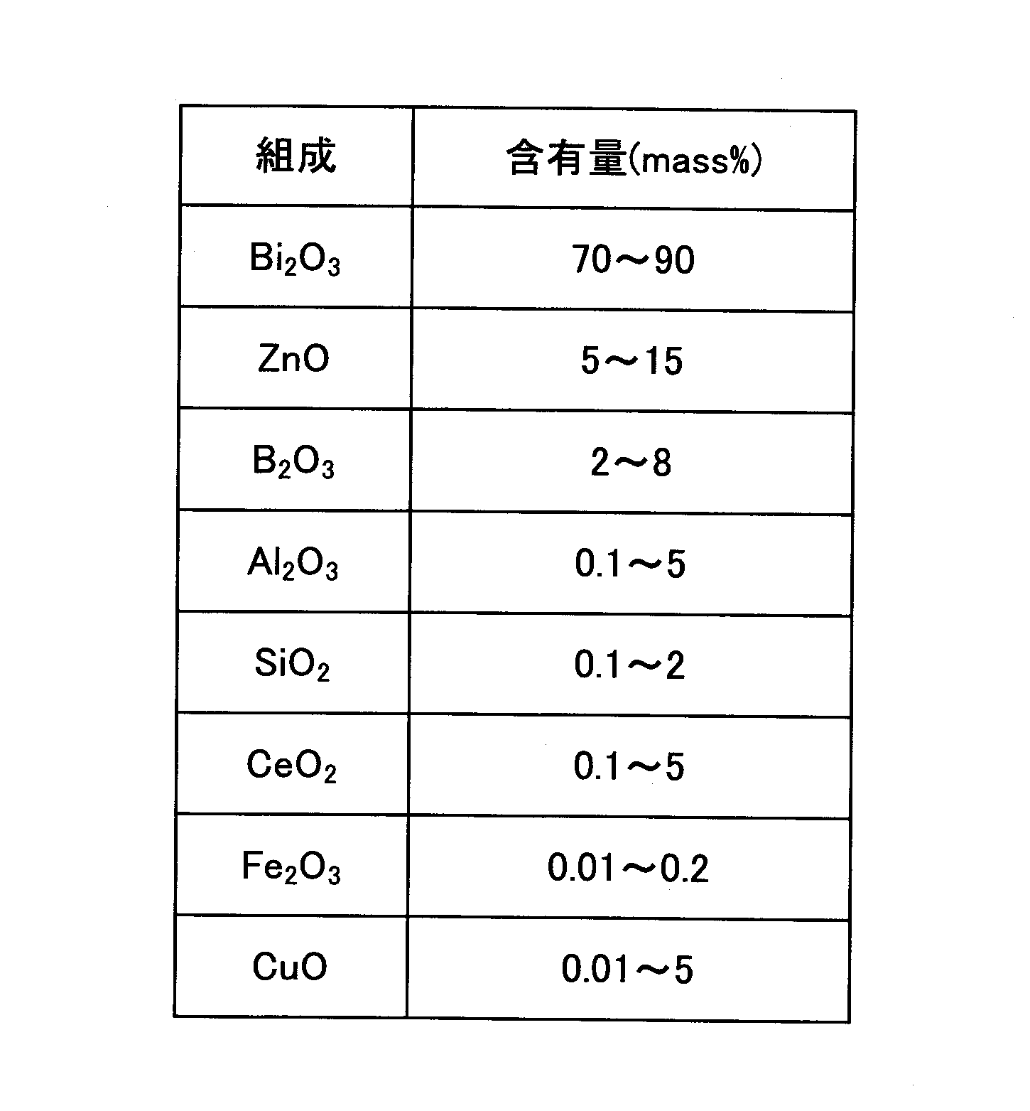

次に、第1の接合層560a、560bを介して対向するように、第1のベースガラス510と第2のベースガラス520が積層され、組立体が構成される。
ここで、組立体は、第2のベースガラス520が第1のベースガラス510上の第1の接合層560a、560bとは接触しないようにして構成される。第2のベースガラス520の第1の表面522上に第2の接合層が存在する場合、同様に、組立体は、第1のベースガラス510の第1の表面512と第2のベースガラス520の第1の表面522が対向するものの、第1のベースガラス510が第2のベースガラス520上の第2の接合層とは接触しないようにして構成される。
このように組立体を構成するのは、第1のベースガラス510(の第1の接合層560a、560b)と第2のベースガラス520とをこの段階で接触させてしまうと、後に、両ベースガラス510、520の間の間隙部を減圧状態にすることが難しくなるためである。
図7には、形成される組立体の一構成例を概略的に示す。図7(a)は、組立体の側面図(断面図)であり、図7(b)は、組立体の底面図である。
図7に示すように、組立体600は、第1のベースガラス510の上部に第2のベースガラス520を隙間を空けて配置することにより構成される。また、組立体600は、さらに隙間形成手段602を備える。
隙間形成手段602は、第1のベースガラス510上に第2のベースガラス520を配置した際に、第2のベースガラス520が第1の接合層560a、560bと接触しないようにする役割を有する。
図7の例では、隙間形成手段602は、第2のベースガラス520の第1の表面522と当接し、これを支持する支持部分603を有する。隙間形成手段602の支持部分603は、組立体600の各コーナー部4箇所に配置される(図7(b)参照)。
なお、図7に示した組立体600の構成は、単なる一例に過ぎない。すなわち、第2のベースガラス520が第1のベースガラス510上の第1の接合層560a、560bと接触しない構成を有する限り(および第1のベースガラス510が第2のベースガラス520上の第2の接合層と接触しない構成を有する限り)、組立体はいかなる構成を有しても良い。例えば、第1のベースガラス510と第2のベースガラス520は、上下関係が逆になっていても良い。
また、図7の例では、第1のベースガラス510は、4箇所のコーナー部511が略三角形状に切除された形状を有し、隙間形成手段602を配置した際に、第1のベースガラス510が隙間形成手段602の支持部分603と干渉しないようになっている。このため、隙間形成手段602の支持部分603は、容易に設置することができる。
ただし、第1のベースガラス510のこのようなコーナー部511の形状加工は、必ずしも必要ではない。例えば、同様の効果を得るため、第1のベースガラス510の寸法を、第2のベースガラス520に比べて、一回り小さく選定しても良い。
このように、第1のベースガラス510と第2のベースガラス520の間に、隙間が形成された組立体600が構成される。
(ステップS130)
次に、ステップS120で構成された組立体600が加熱される。これにより、第1の接合層560a、560bが軟化する。また、第2の接合層が存在する場合、第2の接合層も軟化する。
次に、ステップS120で構成された組立体600が加熱される。これにより、第1の接合層560a、560bが軟化する。また、第2の接合層が存在する場合、第2の接合層も軟化する。
加熱温度は、第1の接合層560a、560bの種類によって変化する。例えば、第1の接合層560a、560bがガラス固化層の場合、組立体600の加熱温度は、ガラス固化層の軟化点を少し超えた温度であっても良い。例えば、第1の接合層560a、560bが前述の表1または表2に示したような組成のガラス固化層の場合、組立体600の加熱温度は、約470℃~約500℃程度であっても良い。
なお、この段階では、隙間形成手段602により、第1のベースガラス510と第2のベースガラス520の間には、依然として、隙間が確保された状態が維持される。
(ステップS140)
次に、組立体600は、加熱された状態のまま(すなわち、第1の接合層560a、560bが軟化した状態のまま)、例えば真空チャンバ内に配置され、減圧環境に晒される。
次に、組立体600は、加熱された状態のまま(すなわち、第1の接合層560a、560bが軟化した状態のまま)、例えば真空チャンバ内に配置され、減圧環境に晒される。
この減圧環境における真空度は、特に限られないが、高真空環境にするほど、最終的に得られる真空複層ガラス100の間隙部130の真空度が向上する。減圧環境における真空度は、例えば、1×10⁻⁵Pa~10Paの範囲であり、好ましくは、0.1Pa以下である。
その後、組立体600およびその周囲が十分に減圧状態に達すると、組立体600において、隙間形成手段602の支持部分603が、例えば機械的および/または電気的に、あるいはその他の手段で、第2のベースガラス520から取り外される。これにより、第1のベースガラス510と第2のベースガラス520が第1の接合層560a、560bを介して接触され、積層体が構成される。
図8には、積層体700の概略的な断面図を示す。図8に示すように、隙間形成手段602が水平方向(X方向)に沿って、組立体から移動されることにより、第2のベースガラス520が落下し、第2のベースガラス520が第1の接合層560a、560bに接触した状態となり、積層体700が構成される。
第1の接合層560a、560bは、軟化状態にあるため、積層体700の構成により、第1のベースガラス510と第2のベースガラス520とが第1の接合層560a、560bを介して結合される。これにより、第1のベースガラス510と第2のベースガラス520との間には、複数の間隙部730が形成される。組立体600の段階から継続されている減圧環境下において間隙部730が形成されるため、これらの間隙部730は、真空状態となる。
その後、積層体700は、高温のまま、または降温後に真空チャンバから取り出される。第1の接合層560a、560bが室温まで冷却された後には、第1の接合層560a、560bによって、第1のベースガラス510と第2のベースガラス520とが完全に結合される。
(ステップS150)
次に、積層体700が切断され、複数の真空複層ガラスが分離形成される。
次に、積層体700が切断され、複数の真空複層ガラスが分離形成される。
例えば、図9に示した底面を有するような積層体700の場合、接合層560aと接合層560bの間の線Lに沿って、積層体700を厚さ方向に切断することにより、真空複層ガラス800aおよび真空複層ガラス800bを製造することができる。切断手段は、例えば、ウォータージェットを用いることができる。ウォータージェットによって、第1のベースガラス510と第2のベースガラス520とを同時に切断することができる。
必要な場合、さらに、各真空複層ガラス800a、800bにおいて、3つの非切断辺を所望の位置で切断し、真空複層ガラス800aの第1の接合層560a、および真空複層ガラス800bの第1の接合層560bの端面からの位置を適当な寸法に調整しても良い。
以上の工程により、複数の真空複層ガラス800a、800bが製造される。
このような本発明による真空複層ガラスの第1の製造方法では、2つ以上の真空複層ガラスを、1回の真空処理工程(ステップS140の工程)で製造することができる。
従来のような各種寸法形状の真空複層ガラスを「一品生産式」製造方法では、一つの製品毎に、真空処理工程を1回実施する必要があるため、生産効率の向上および製造コストの抑制を図ることが難しい。
これに対して、本発明による真空複層ガラスの第1の製造方法では、たとえ、製造する真空複層ガラスの寸法形状が異なっていても、2つ以上の真空複層ガラスを、1回の真空処理工程(ステップS140の工程)で製造することができる。このため、本発明による真空複層ガラスの第1の製造方法では、生産効率の向上および/または製造コストの抑制が可能となる。
以上、図1に示した構造の真空複層ガラス100を製造する場合を例に、第1の製造方法ついて説明した。
ここで、図4に示したような第4の真空複層ガラス400を製造する場合は、ステップS140とステップS150の間に、さらに、
(vi)積層体700に中間膜を介して第3のベースガラスを積層して、合わせガラス組立体を構成するステップ(ステップS160)、および
(vii)前記合わせガラス組立体を加熱、加圧して、前記積層体700と第3のベースガラスを結合するステップ(ステップS170)
が追加されても良い。
(vi)積層体700に中間膜を介して第3のベースガラスを積層して、合わせガラス組立体を構成するステップ(ステップS160)、および
(vii)前記合わせガラス組立体を加熱、加圧して、前記積層体700と第3のベースガラスを結合するステップ(ステップS170)
が追加されても良い。
なお、これらのステップS160およびS170には、一般的な合わせガラスの製造工程として当業者に知られている方法を用いることができる。例えば、合わせガラス組立体を加熱して仮圧着させた後に、オートクレーブによる加熱加圧する本圧着処理を行う。
この場合、ステップ150において、本圧着後の合わせガラス組立体を平面視で各封着層を分離するように切断し、図4に示す複数の第4の真空複層ガラス400が得られる。
(第2の製造方法)
次に、図10を参照して、本発明の第2実施形態による真空複層ガラスの製造方法(第2の製造方法)について説明する。ここでも、図1に示した構造の真空複層ガラスを製造する場合を例に、第2の製造方法ついて説明する。
次に、図10を参照して、本発明の第2実施形態による真空複層ガラスの製造方法(第2の製造方法)について説明する。ここでも、図1に示した構造の真空複層ガラスを製造する場合を例に、第2の製造方法ついて説明する。
図10には、本発明の第2の製造方法のフローを概略的に示す。
図10に示すように、本発明の第2の製造方法は、
(i)第1のベースガラスおよび第2のベースガラスを準備し、第1のベースガラスの第1の表面に、少なくとも2つの額縁状に形成された第1の接合層を配置するステップ(ステップS210)と、
(ii)前記第1の接合層を介して対向するように、前記第1のベースガラスと前記第2のベースガラスを積層し、前記第2のベースガラスが前記第1の接合層と非接触の状態の組立体を構成するステップ(ステップS220)と、
(iii)前記組立体を減圧環境下に配置した後、前記第2のベースガラスが前記第1の接合層と接触した状態の積層体を構成するステップ(ステップS230)と、
(iv)前記積層体を加熱し、前記接合層を軟化させるステップ(ステップS240)と、
(v)各第1の接合層を分離するように前記積層体を切断し、少なくとも2つの真空複層ガラスを得るステップ(ステップS250)と、
を有する。
(i)第1のベースガラスおよび第2のベースガラスを準備し、第1のベースガラスの第1の表面に、少なくとも2つの額縁状に形成された第1の接合層を配置するステップ(ステップS210)と、
(ii)前記第1の接合層を介して対向するように、前記第1のベースガラスと前記第2のベースガラスを積層し、前記第2のベースガラスが前記第1の接合層と非接触の状態の組立体を構成するステップ(ステップS220)と、
(iii)前記組立体を減圧環境下に配置した後、前記第2のベースガラスが前記第1の接合層と接触した状態の積層体を構成するステップ(ステップS230)と、
(iv)前記積層体を加熱し、前記接合層を軟化させるステップ(ステップS240)と、
(v)各第1の接合層を分離するように前記積層体を切断し、少なくとも2つの真空複層ガラスを得るステップ(ステップS250)と、
を有する。
ここで、ステップS210およびステップS220は、それぞれ、前述の第1の製造方法におけるステップS110およびステップS120と同様の工程を有する。そのため、ここでは、ステップS230以降のステップについて説明する。
(ステップS230)
例えば前述の図7に示したような組立体600を、例えば真空チャンバ内に配置することにより、組立体600を減圧環境下に配置する。
例えば前述の図7に示したような組立体600を、例えば真空チャンバ内に配置することにより、組立体600を減圧環境下に配置する。
前述のように、この減圧環境における真空度は、例えば、1×10⁻⁵Pa~10Paの範囲であっても良く、好ましくは、0.1Pa以下である。
この段階では、隙間形成手段602により、組立体600において、第1のベースガラス510と第2のベースガラス520の間の空間は、依然として開放された状態となっている。従って、組立体600を減圧環境下に配置することにより、第1のベースガラス510と第2のベースガラス520の間の空間を真空状態にすることができる。
その後、組立体600において、隙間形成手段602の支持部分603が、例えば機械的および/または電気的に、あるいはその他の手段で、第2のベースガラス520から取り外される。これにより、第1のベースガラス510と第2のベースガラス520が第1の接合層560a、560bを介して接触され、前述の図8に示したような構成の積層体700が形成される。
一旦、積層体700が構成されると、第1のベースガラス520と第2のベースガラス520の間の間隙部730は、外部環境と遮断される。しかしながら、前段の組立体600の段階で、第1のベースガラス520と第2のベースガラス520の間の空間は、十分に減圧処理されている。このため、積層体700においても、間隙部730は、真空状態に維持される。
(ステップS240)
次に、積層体700が加熱され、第1の接合層560a、560bが軟化される。
次に、積層体700が加熱され、第1の接合層560a、560bが軟化される。
これにより、第1のベースガラス510と第2のベースガラス520とが第1の接合層560a、560bを介して結合される。
その後、積層体700は、高温のまま、または降温後に真空チャンバから取り出される。第1の接合層560a、560bが室温まで冷却された後には、第1の接合層560a、560bによって、第1のベースガラス510と第2のベースガラス520とが完全に結合される。
(ステップS250)
その後は、第1の製造方法におけるステップS150と同様の方法により、積層体700が所定の位置で切断される。これにより、複数の真空複層ガラスを製造することができる。
その後は、第1の製造方法におけるステップS150と同様の方法により、積層体700が所定の位置で切断される。これにより、複数の真空複層ガラスを製造することができる。
このような本発明による真空複層ガラスの第2の製造方法においても、第1の製造方法の場合と同様の効果、すなわち、2つ以上の真空複層ガラスを、1回の真空処理工程(ステップS230~ステップS240の工程)で製造することができるという効果を得ることができる。このため、本発明による真空複層ガラスの第2の製造方法においても、生産効率の向上および/または製造コストの抑制が可能となる。
なお、図4に示したような第4の真空複層ガラス400を製造する場合は、ステップS240とステップS250の間に、さらに、
(vi)積層体700に中間膜を介して第3のベースガラスを積層して、合わせガラス組立体を構成するステップ、および
(vii)前記合わせガラス組立体を加熱、加圧して、前記積層体700と第3のベースガラスを結合するステップ
が追加されても良い。
(vi)積層体700に中間膜を介して第3のベースガラスを積層して、合わせガラス組立体を構成するステップ、および
(vii)前記合わせガラス組立体を加熱、加圧して、前記積層体700と第3のベースガラスを結合するステップ
が追加されても良い。
(第3の製造方法)
次に、図11を参照して、本発明の第3実施形態による真空複層ガラスの製造方法(第3の製造方法)について説明する。ここでも、図1に示した構造の真空複層ガラスを製造する場合を例に、第3の製造方法ついて説明する。
次に、図11を参照して、本発明の第3実施形態による真空複層ガラスの製造方法(第3の製造方法)について説明する。ここでも、図1に示した構造の真空複層ガラスを製造する場合を例に、第3の製造方法ついて説明する。
図11には、本発明の第3の製造方法のフローを概略的に示す。
図11に示すように、本発明の第3の製造方法は、
(i)第1のベースガラスおよび第2のベースガラスを準備し、前記第1のベースガラスの第1の表面に、少なくとも2つの額縁状に形成された第1の接合層を配置するステップ(ステップS310)と、
(ii)前記第1の接合層を介して対向するように、前記第1のベースガラスと前記第2のベースガラスを積層し、前記第2のベースガラスが前記第1の接合層と非接触の状態の組立体を構成するステップ(ステップS320)と、
(iii)前記組立体を減圧環境下に配置した後、前記組立体を加熱し、前記第1の接合層を軟化させるステップ(ステップS330)と、
(iv)前記第2のベースガラスが前記第1の接合層と接触した状態の積層体を構成するステップ(ステップS340)と、
(v)各第1の接合層を分離するように前記積層体を切断し、少なくとも2つの真空複層ガラスを得るステップ(ステップS350)と、
を有する。
(i)第1のベースガラスおよび第2のベースガラスを準備し、前記第1のベースガラスの第1の表面に、少なくとも2つの額縁状に形成された第1の接合層を配置するステップ(ステップS310)と、
(ii)前記第1の接合層を介して対向するように、前記第1のベースガラスと前記第2のベースガラスを積層し、前記第2のベースガラスが前記第1の接合層と非接触の状態の組立体を構成するステップ(ステップS320)と、
(iii)前記組立体を減圧環境下に配置した後、前記組立体を加熱し、前記第1の接合層を軟化させるステップ(ステップS330)と、
(iv)前記第2のベースガラスが前記第1の接合層と接触した状態の積層体を構成するステップ(ステップS340)と、
(v)各第1の接合層を分離するように前記積層体を切断し、少なくとも2つの真空複層ガラスを得るステップ(ステップS350)と、
を有する。
ここで、ステップS310およびステップS320は、それぞれ、前述の第1の製造方法におけるステップS110およびステップS120と同様の工程を有する。そのため、ここでは、ステップS330以降のステップについて説明する。
(ステップS330)
例えば前述の図7に示したような組立体600を、例えば真空チャンバ内に配置することにより、組立体600を減圧環境下に配置する。
例えば前述の図7に示したような組立体600を、例えば真空チャンバ内に配置することにより、組立体600を減圧環境下に配置する。
前述のように、この減圧環境における真空度は、例えば、1×10⁻⁵Pa~10Paの範囲であっても良く、好ましくは、0.1Pa以下である。
この段階では、隙間形成手段602により、組立体600において、第1のベースガラス510と第2のベースガラス520の間の空間は、依然として開放された状態となっている。従って、組立体600を減圧環境下に配置することにより、第1のベースガラス510と第2のベースガラス520の間の空間を真空状態にすることができる。
次に、減圧環境下に配置されたまま、組立体600が加熱され、第1の接合層560a、560bが軟化される。
組立体600の加熱温度は、第1の接合層560a、560bが軟化される温度である限り、特に限られない。前述のように、第1の接合層560a、560bがガラス固化層で構成される場合、組立体600の加熱温度は、例えば約470℃~約500℃の範囲であっても良い。
(ステップS340)
次に、組立体600において、隙間形成手段602の支持部分603が、例えば機械的および/または電気的に、あるいはその他の手段で、第2のベースガラス520から取り外される。これにより、第1のベースガラス510と第2のベースガラス520が第1の接合層560a、560bを介して接触され、前述の図8に示したような構成の積層体700が形成される。
次に、組立体600において、隙間形成手段602の支持部分603が、例えば機械的および/または電気的に、あるいはその他の手段で、第2のベースガラス520から取り外される。これにより、第1のベースガラス510と第2のベースガラス520が第1の接合層560a、560bを介して接触され、前述の図8に示したような構成の積層体700が形成される。
一旦、積層体700が構成されると、第1のベースガラス520と第2のベースガラス520の間の空間は、外部環境と遮断される。これにより、間隙部730が形成される。
ここで、前段の組立体600の段階で、第1のベースガラス520と第2のベースガラス520の間の空間は、十分に減圧処理されている。このため、積層体700においても、間隙部730は、真空状態に維持される。
また、第1の接合層560a、560bは、軟化状態にあるため、積層体700の構成により、第1のベースガラス510と第2のベースガラス520とが第1の接合層560a、560bを介して結合される。
その後、積層体700は、高温のまま、または降温後に真空チャンバから取り出される。第1の接合層560a、560bが室温まで冷却された後には、第1の接合層560a、560bによって、第1のベースガラス510と第2のベースガラス520とが完全に結合される。
(ステップS350)
その後は、第1の製造方法におけるステップS150と同様の方法により、積層体700が所定の位置で切断される。これにより、複数の真空複層ガラスを製造することができる。
その後は、第1の製造方法におけるステップS150と同様の方法により、積層体700が所定の位置で切断される。これにより、複数の真空複層ガラスを製造することができる。
このような本発明による真空複層ガラスの第3の製造方法においても、第1の製造方法の場合と同様の効果、すなわち、2つ以上の真空複層ガラスを、1回の真空処理工程(ステップS330~S340の工程)で製造することができるという効果を得ることができる。このため、本発明による真空複層ガラスの第3の製造方法においても、生産効率の向上および/または製造コストの抑制が可能となる。
なお、図4に示したような第4の真空複層ガラス400を製造する場合は、ステップS340とステップS350の間に、さらに、
(vi)積層体700に中間膜を介して第3のベースガラスを積層して、合わせガラス組立体を構成するステップ、および
(vii)前記合わせガラス組立体を加熱、加圧して、前記積層体700と第3のベースガラスを結合するステップ
が追加されても良い。
(vi)積層体700に中間膜を介して第3のベースガラスを積層して、合わせガラス組立体を構成するステップ、および
(vii)前記合わせガラス組立体を加熱、加圧して、前記積層体700と第3のベースガラスを結合するステップ
が追加されても良い。
(第4の製造方法)
次に、図12を参照して、本発明の第4実施形態による真空複層ガラスの製造方法(第4の製造方法)について説明する。なお、ここでは、図2に示した構造の真空複層ガラスを製造する場合を例に、第4の製造方法ついて説明する。ただし、説明の明確化および簡略化のため、ここでも、図2におけるピラー290に関する説明は、省略する。
次に、図12を参照して、本発明の第4実施形態による真空複層ガラスの製造方法(第4の製造方法)について説明する。なお、ここでは、図2に示した構造の真空複層ガラスを製造する場合を例に、第4の製造方法ついて説明する。ただし、説明の明確化および簡略化のため、ここでも、図2におけるピラー290に関する説明は、省略する。
図12には、本発明の第4の製造方法のフローを概略的に示す。また、図13~図16には、本発明の第4の製造方法の各工程における模式的な組立状態図を示す。
図12に示すように、本発明の第4の製造方法は、
(i)第1のベースガラスおよび第2のベースガラスを準備し、前記第1のベースガラスの第1の表面に、少なくとも2つの第1の接合層を配置し、前記第2のベースガラスの第1の表面に、前記第1の接合層と同数の、第2の接合層を配置するステップであって、各第1の接合層は、中央部が除去された額縁状に形成され、各第2の接合層は、中央部が除去された額縁状に形成される、ステップ(ステップS410)と、
(ii)前記第1のベースガラスの第1の接合層と接するように、金属部材を配置するステップであって、前記金属部材は、各第1の接合層の前記中央部に対応する開口を有するステップ(ステップS420)と、
(iii)前記第1の接合層と前記第2の接合層が前記金属部材を介して対向するように、前記第1のベースガラスと前記第2のベースガラスを積層し、これにより、前記第2の接合層が前記金属部材と非接触の状態の組立体を構成するステップ(ステップS430)と、
(iv)前記組立体を加熱し、第1および第2の接合層を軟化させるステップ(ステップS440)と、
(v)前記組立体を減圧環境下に配置した後、前記金属部材と前記第2の接合層が接触した状態の積層体を構成するステップであって、これにより、前記第1の接合層の前記中央部、前記金属部材の開口、前記第2の接合層の前記中央部により、複数の間隙部が形成されるステップ(ステップS450)と、
(vi)各第1の接合層を分離するように前記積層体を切断し、少なくとも2つの真空複層ガラスを得るステップ(ステップS460)と、
を有する。
(i)第1のベースガラスおよび第2のベースガラスを準備し、前記第1のベースガラスの第1の表面に、少なくとも2つの第1の接合層を配置し、前記第2のベースガラスの第1の表面に、前記第1の接合層と同数の、第2の接合層を配置するステップであって、各第1の接合層は、中央部が除去された額縁状に形成され、各第2の接合層は、中央部が除去された額縁状に形成される、ステップ(ステップS410)と、
(ii)前記第1のベースガラスの第1の接合層と接するように、金属部材を配置するステップであって、前記金属部材は、各第1の接合層の前記中央部に対応する開口を有するステップ(ステップS420)と、
(iii)前記第1の接合層と前記第2の接合層が前記金属部材を介して対向するように、前記第1のベースガラスと前記第2のベースガラスを積層し、これにより、前記第2の接合層が前記金属部材と非接触の状態の組立体を構成するステップ(ステップS430)と、
(iv)前記組立体を加熱し、第1および第2の接合層を軟化させるステップ(ステップS440)と、
(v)前記組立体を減圧環境下に配置した後、前記金属部材と前記第2の接合層が接触した状態の積層体を構成するステップであって、これにより、前記第1の接合層の前記中央部、前記金属部材の開口、前記第2の接合層の前記中央部により、複数の間隙部が形成されるステップ(ステップS450)と、
(vi)各第1の接合層を分離するように前記積層体を切断し、少なくとも2つの真空複層ガラスを得るステップ(ステップS460)と、
を有する。
以下、各ステップについて詳しく説明する。
(ステップS410)
まず、第1のベースガラスおよび第2のベースガラスが準備される。第1のベースガラスの第1の表面には、少なくとも2つの額縁状の接合層(第1の接合層)が形成される。また、第2のベースガラスの第1の表面には、第1の接合層と同数の、額縁状の第2の接合層が形成される。後述するように、第2の接合層は、第1の接合層と「対応する」位置に設置される。
まず、第1のベースガラスおよび第2のベースガラスが準備される。第1のベースガラスの第1の表面には、少なくとも2つの額縁状の接合層(第1の接合層)が形成される。また、第2のベースガラスの第1の表面には、第1の接合層と同数の、額縁状の第2の接合層が形成される。後述するように、第2の接合層は、第1の接合層と「対応する」位置に設置される。
図13には、第1のベースガラスおよび第2のベースガラスを示す。
図13に示すように、第1のベースガラス910は、第1の表面912を有し、この第1の表面912には、2つの第1の接合層960a、960bが設置されている。同様に、第2のベースガラス920は、第1の表面922を有し、この第1の表面922には、2つの第2の接合層961a、961bが設置されている。第1の接合層960a、960bおよび第2の接合層961a、961bは、例えば、前述のようなガラス固化層で構成されても良い。
第1のベースガラス910の寸法形状は、第2のベースガラス920の寸法形状と略同等であっても良い。なお、図13に示す例では、第1のベースガラス910は、4つのコーナー部911が略三角形形状となるように切除されている。しかしながら、この形状は、必ずしも必要ではない。
第2のベースガラス920に設置された第2の接合層961aは、以降のステップにおいて、第1のベースガラス910と第2のベースガラス920を積層した際に、第1のベースガラス910に設置された第1の接合層960aと「対応する」位置に配置されている。同様に、第2のベースガラス920に設置された第2の接合層961bは、以降のステップにおいて、第1のベースガラス910と第2のベースガラス920を積層した際に、第1のベースガラス910に設置された第1の接合層960bと「対応する」位置に配置されている。
ここで、2つの部材が「対応する」(位置)という表現は、2つの部材を含む構造部が形成された際に、該構造部が適正に機能する位置関係で、2つの部材が相互に対して配置された状態を意味する。例えば、2つの部材が「対応する」位置には、2つの部材を含む構造部が形成された際に、両部材が相互に重なり合う状態が含まれる。
例えば、図13の例では、第1の接合層960aおよび第2の接合層961aは、以降のステップS450において積層体が構成された際、または最終的に真空複層ガラスが製造された際に、適正なシール構造が形成されるような位置関係で、それぞれのベースガラス910、920上に配置されている。同様に、第1の接合層960bおよび第2の接合層961bは、以降のステップS450において積層体が構成された際に、または最終的に真空複層ガラスが製造された際に、適正なシール構造が形成されるような位置関係で、それぞれのベースガラス910、920上に配置されている。
なお、図13の例では、第1の接合層および第2の接合層は、それぞれ2つしか形成されていないが、第1の接合層および第2の接合層の数は、それぞれ3つ以上であっても良い。第1の接合層および第2の接合層の数によって、最終的に製造される真空複層ガラスの数が定められる。
(ステップS420)
次に、第1のベースガラス910の第1の接合層960a、960bと接するようにして、第1のベースガラス910の上に金属部材が配置される。
次に、第1のベースガラス910の第1の接合層960a、960bと接するようにして、第1のベースガラス910の上に金属部材が配置される。
金属部材の材料は、例えば、アルミニウム金属もしくは合金、チタン金属もしくは合金、銅金属もしくは合金、またはステンレス鋼等であっても良い。また、金属部材は、板状または箔状であり、5μm~500μmの範囲の厚さを有しても良い。
図14には、第1のベースガラス910の上に金属部材が配置される様子を示す。
図14に示すように、金属部材955は、第1のベースガラス910とほぼ同等の外寸法および形状を有する。
ここで、金属部材955は、第1の接合層960aに対応する開口957aおよび第1の接合層960bに対応する開口957bを有する。従って、金属部材955は、最終的に真空複層ガラスが製造された際には、図2に示したようなシール構造250を構成する、額縁状の金属部材255として利用することができる。
ハンドリングの際に金属部材955と第1のベースガラス910の間の位置ずれを防止するため、金属部材955は、第1の接合層960a、960bと仮留めしても良い。
なお、図14の例では、金属部材955は、単一の一体化部品として提供されている。しかしながら、別の態様として、第1の接合層960a、960bのそれぞれに対応した、複数の額縁状の金属部材を準備し、これらを各第1の接合層960a、960b上に配置しても良い。ただし、図14のような単一の金属部材955を使用した場合、一回の配置操作で金属部材の配置が完了するため、金属部材の第1のベースガラス910上への設置が容易となる。
以上の工程により、第1のベースガラス910の第1の接合層960a、960bの上に、金属部材955が配置される。
(ステップS430)
次に、第1の接合層960a、960bと第2の接合層961a、961bとが金属部材955を介して対向するように、第1のベースガラス910と第2のベースガラス920が積層され、組立体が構成される。
次に、第1の接合層960a、960bと第2の接合層961a、961bとが金属部材955を介して対向するように、第1のベースガラス910と第2のベースガラス920が積層され、組立体が構成される。
この際には、第2のベースガラス920は、第2の接合層961a、961bが金属部材955と接触しないようにして、第1のベースガラス910上に配置される。
図15には、組立体の一構成例を概略的に示す。図15(a)は、組立体の断面図であり、図15(b)は、組立体の底面図である。なお、図15(b)において、第2の接合層961a、961bは、明確化のため、省略されている。
図15に示すように、組立体1000は、金属部材955が設置された第1のベースガラス910の上部に、第2のベースガラス920を隙間を空けて配置することにより構成される。また、組立体1000は、前述の隙間形成手段602を備える。
隙間形成手段602により、第2の接合層961a、961bが金属部材955と接触しないようにして、第2のベースガラス920を第1のベースガラス910上に配置することが可能となる。
図15の例では、隙間形成手段602は、第2のベースガラス920の第1の表面922と当接し、これを支持する支持部分603を有する。隙間形成手段602の支持部分603は、組立体1000の各コーナー部4箇所に配置される(図15(b)参照)。
なお、図15の例では、対応する第1の接合層と第2の接合層(例えば、第1の接合層960aと第2の接合層961a、および第1の接合層960bと第2の接合層961b)は、組立体1000を厚さ方向から見たとき、相互に重ならないような位置に配置されている。しかしながら、これは一例であって、対応する第1の接合層と第2の接合層は、一部または全部が重なっていても良い。ただし、前述のように、図15のような関係で第1の接合層と第2の接合層を配置した場合、最終的に製造される真空複層ガラスにおいて、熱応力緩和能を有するシール構造が得られるという効果が得られる。
また、図15の例では、第1のベースガラス910および金属部材955は、4箇所のコーナー部が略三角形状に切除された形状を有し、隙間形成手段602を配置した際に、第1のベースガラス910および金属部材955が隙間形成手段602の支持部分603と干渉しないようになっている。ただし、第1のベースガラス910および金属部材955のこのようなコーナー部の形状加工は、必ずしも必要ではない。例えば、同様の効果を得るため、第1のベースガラス910および金属部材955の寸法を、第2のベースガラス920に比べて、一回り小さく選定しても良い。
このようにして、第1のベースガラス910と第2のベースガラス920の間に隙間が形成された組立体1000が構成される。
(ステップS440)
次に、ステップS430で構成された組立体1000が加熱される。これにより、第1の接合層960a、960b、および第2の接合層961a、961bが軟化する。
次に、ステップS430で構成された組立体1000が加熱される。これにより、第1の接合層960a、960b、および第2の接合層961a、961bが軟化する。
加熱温度は、例えば、第1の接合層960a、960b、および第2の接合層961a、961bがラス固化層の場合、約470℃~約500℃程度であっても良い。
なお、この段階では、隙間形成手段602により、金属部材955と第2のベースガラス920の間には、依然として、開放空間が確保された状態が維持される。
(ステップS450)
次に、組立体1000は、加熱された状態のまま、例えば真空チャンバ内に配置され、減圧環境に晒される。
次に、組立体1000は、加熱された状態のまま、例えば真空チャンバ内に配置され、減圧環境に晒される。
この減圧環境における真空度は、例えば、1×10⁻⁵Pa~10Paの範囲であり、好ましくは、0.1Pa以下である。
その後、組立体1000の周囲が十分に減圧処理されてから、組立体1000において、隙間形成手段602の支持部分603が、例えば機械的および/または電気的に、あるいはその他の手段で、第2のベースガラス920から取り外される。これにより、第1のベースガラス910と第2のベースガラス920が第1の接合層960a、960b、金属部材955、および第2の接合層961a、961bを介して接触され、積層体が構成される。
図16には、得られる積層体1100の概略的な断面図を示す。図16に示すように、隙間形成手段602が水平方向(X方向)に沿って、組立体から移動されることにより、第2のベースガラス920が落下し、第2のベースガラス920の第2の接合層961a、961bが金属部材955に接触した状態となり、積層体1100が構成される。
なお、この際には、第2のベースガラス920の落下による加圧により、金属部材955は、平坦な断面形状から、段差を有する断面形状に変形しても良い。
第1の接合層960a、960b、および第2の接合層961a、961bは、軟化状態にあるため、積層体1100の構成により、第1のベースガラス910と第2のベースガラス920とが、金属部材955を介して結合される。
ここで、金属部材955は、それぞれ、第1の接合層960aおよび第2の接合層961aに対応する開口957a、ならびに第1の接合層960bおよび第2の接合層961bに対応する開口957bを有する。また、第2の接合層961a、961bは、それぞれ、第1の接合層960a、960bに対応する位置に配置されている。
このため、積層体1100が構成された際に、第1のベースガラス910と第2のベースガラス920との間には、複数の間隙部1130が形成される。これらの間隙部1130は、組立体1000の段階から継続される減圧環境下において形成されるため、これらの間隙部1130は、真空状態となる。
その後、積層体1100は、高温のまま、または降温後に真空チャンバから取り出される。第1の接合層960a、960b、および第2の接合層961a、961bが室温まで冷却された後には、両接合層によって、第1のベースガラス910と第2のベースガラス920とが、金属部材955を介して完全に結合される。
(ステップS460)
次に、積層体1100が切断され、複数の真空複層ガラスが分離形成される。
次に、積層体1100が切断され、複数の真空複層ガラスが分離形成される。
例えば、図16に示す積層体1100の場合、破線L2の位置で積層体1100を厚さ方向に切断することにより、2つの真空複層ガラスを製造することができる。
このように、第4の製造方法により、前述の図2に示したようなシール構造250を有する真空複層ガラス200が複数製造される。
この第4の製造方法においても、前述の第1~第3の製造方法と同様の効果が得られることは明らかであろう。
なお、図12に示した第4の製造方法では、第1の製造方法の場合と同様、組立体1000は、ステップS440において大気環境下で加熱された後、ステップS450において減圧環境に配置され、この減圧環境下において積層体が構成される。
しかしながら、この変形例として、組立体1000は、前述の第2の製造方法のように、室温のまま減圧環境に配置され、ここで積層体とされ(ステップS230参照)、その後、減圧環境下で加熱されても良い(ステップS240参照)。
あるいは、別の変形例として、組立体1000は、前述の第3の製造方法のように、室温のまま減圧環境に配置され、加熱され(ステップS330参照)、その後、積層体が構成されても良い(ステップS340参照)。
(第5の製造方法)
次に、図17~図22を参照して、本発明の第5実施形態による真空複層ガラスの製造方法(第5の製造方法)について説明する。なお、ここでは、図3に示した構造の真空複層ガラスを製造する場合を例に、第5の製造方法ついて説明する。ただし、説明の明確化および簡略化のため、ここでも、図3におけるピラー390に関する説明は、省略する。
次に、図17~図22を参照して、本発明の第5実施形態による真空複層ガラスの製造方法(第5の製造方法)について説明する。なお、ここでは、図3に示した構造の真空複層ガラスを製造する場合を例に、第5の製造方法ついて説明する。ただし、説明の明確化および簡略化のため、ここでも、図3におけるピラー390に関する説明は、省略する。
図17には、本発明の第5の製造方法のフローを概略的に示す。また、図18~図22には、本発明の第5の製造方法の各工程における模式的な組立状態図を示す。
図17に示すように、本発明の第5の製造方法は、
(i)第1のベースガラスおよび第2のベースガラスを準備し、前記第1のベースガラスの第1の表面に、少なくとも2つの第1の接合層を配置し、前記第2のベースガラスの第1の表面に、前記第1の接合層と同数の、第2の接合層を配置するステップであって、各第1の接合層は、中央部が除去された額縁状に形成され、各第2の接合層は、中央部が除去された額縁状に形成されるステップ(ステップS510)と、
(ii)前記第1のベースガラスの第1の接合層と接するように、第1の金属部材を配置し、前記第2のベースガラスの第2の接合層と接するように、第2の金属部材を配置するステップであって、前記第1の金属部材は、各第1の接合層の前記中央部に対応する第1の開口を有し、前記第2の金属部材は、各第2の接合層の前記中央部に対応する第2の開口をするステップ(ステップS520)と、
(iii)前記第1の金属部材の上に、該第1の金属部材の各第1の開口に対応する開口を有する第3の接合層を配置するステップ(ステップS530)と、
(iv)前記第1の金属部材と前記第2の金属部材が前記第3の接合層を介して対向するように、前記第1のベースガラスと前記第2のベースガラスを積層し、これにより、前記第3の接合層が前記第2の金属部材と非接触の状態の組立体を構成するステップ(ステップS540)と、
(v)前記組立体を加熱し、前記第3の接合層を軟化させるステップ(ステップS550)と、
(vi)前記組立体を減圧環境下に配置した後、前記第2の金属部材と前記第3の接合層が接触した状態の積層体を構成するステップであって、これにより、前記第1の接合層の前記中央部、前記第1の金属部材の第1の開口、前記第3の接合層の開口、前記第2の金属部材の第2の開口、および前記第2の接合層の前記中央部により、複数の間隙部が形成されるステップ(ステップS560)と、
(vii)各第1の接合層を分離するように前記積層体を切断し、少なくとも2つの真空複層ガラスを得るステップ(ステップS570)と、
を有する。
(i)第1のベースガラスおよび第2のベースガラスを準備し、前記第1のベースガラスの第1の表面に、少なくとも2つの第1の接合層を配置し、前記第2のベースガラスの第1の表面に、前記第1の接合層と同数の、第2の接合層を配置するステップであって、各第1の接合層は、中央部が除去された額縁状に形成され、各第2の接合層は、中央部が除去された額縁状に形成されるステップ(ステップS510)と、
(ii)前記第1のベースガラスの第1の接合層と接するように、第1の金属部材を配置し、前記第2のベースガラスの第2の接合層と接するように、第2の金属部材を配置するステップであって、前記第1の金属部材は、各第1の接合層の前記中央部に対応する第1の開口を有し、前記第2の金属部材は、各第2の接合層の前記中央部に対応する第2の開口をするステップ(ステップS520)と、
(iii)前記第1の金属部材の上に、該第1の金属部材の各第1の開口に対応する開口を有する第3の接合層を配置するステップ(ステップS530)と、
(iv)前記第1の金属部材と前記第2の金属部材が前記第3の接合層を介して対向するように、前記第1のベースガラスと前記第2のベースガラスを積層し、これにより、前記第3の接合層が前記第2の金属部材と非接触の状態の組立体を構成するステップ(ステップS540)と、
(v)前記組立体を加熱し、前記第3の接合層を軟化させるステップ(ステップS550)と、
(vi)前記組立体を減圧環境下に配置した後、前記第2の金属部材と前記第3の接合層が接触した状態の積層体を構成するステップであって、これにより、前記第1の接合層の前記中央部、前記第1の金属部材の第1の開口、前記第3の接合層の開口、前記第2の金属部材の第2の開口、および前記第2の接合層の前記中央部により、複数の間隙部が形成されるステップ(ステップS560)と、
(vii)各第1の接合層を分離するように前記積層体を切断し、少なくとも2つの真空複層ガラスを得るステップ(ステップS570)と、
を有する。
以下、各ステップについて詳しく説明する。
(ステップS510)
まず、第1のベースガラスおよび第2のベースガラスが準備される。第1のベースガラスの第1の表面には、少なくとも2つの額縁状の第1の接合層が形成される。また、第2のベースガラスの第1の表面には、第1の接合層と同数の、額縁状の第2の接合層が形成される。後述するように、第2の接合層は、第1の接合層と対応する位置に設置される。
まず、第1のベースガラスおよび第2のベースガラスが準備される。第1のベースガラスの第1の表面には、少なくとも2つの額縁状の第1の接合層が形成される。また、第2のベースガラスの第1の表面には、第1の接合層と同数の、額縁状の第2の接合層が形成される。後述するように、第2の接合層は、第1の接合層と対応する位置に設置される。
図18には、第1のベースガラスおよび第2のベースガラスを示す。
図18に示すように、第1のベースガラス1210は、第1の表面1212を有し、この第1の表面1212には、2つの第1の接合層1260a、1260bが設置される。同様に、第2のベースガラス1220は、第1の表面1222を有し、この第1の表面1222には、2つの第2の接合層1261a、1261bが設置される。第1の接合層1260a、1260bおよび第2の接合層1261a、1261bは、例えば、前述のようなガラス固化層で構成されても良い。
第1のベースガラス1210の寸法形状は、第2のベースガラス1220の寸法形状と略同等であっても良い。なお、図18には示されていないが、前述のように、第1のベースガラス1210は、4つのコーナー部が略三角形形状となるように切除されていても良い。
第2のベースガラス1220に設置された第2の接合層1261aは、以降のステップにおいて、第1のベースガラス1210と第2のベースガラス1220を積層した際に、第1のベースガラス1210に設置された第1の接合層1260aと「対応する」位置に配置される。同様に、第2のベースガラス1220に設置された第2の接合層1261bは、以降のステップにおいて、第1のベースガラス1210と第2のベースガラス1220を積層した際に、第1のベースガラス1210に設置された第1の接合層1260bと「対応する」位置に配置される。
(ステップS520)
次に、第1のベースガラス1210の第1の接合層1260a、1260bと接するようにして、第1のベースガラス1210の上に第1の金属部材が配置される。同様に、第2のベースガラス1220の第2の接合層1261a、1261bと接するようにして、第2のベースガラス1220の上に第2の金属部材が配置される。
次に、第1のベースガラス1210の第1の接合層1260a、1260bと接するようにして、第1のベースガラス1210の上に第1の金属部材が配置される。同様に、第2のベースガラス1220の第2の接合層1261a、1261bと接するようにして、第2のベースガラス1220の上に第2の金属部材が配置される。
第1および第2の金属部材の材料は、例えば、アルミニウム金属もしくは合金、チタン金属もしくは合金、銅金属もしくは合金、またはステンレス鋼等であっても良い。また、第1および第2の金属部材は、板状または箔状であり、5μm~500μmの範囲の厚さを有しても良い。
なお、第1および第2の金属部材は、同じ材料で構成されても、異なる材料で構成されても良い。また、第1および第2の金属部材は、同じ寸法形状を有しても、異なる寸法形状を有しても良い。
図19の左図には、第1のベースガラス1210の上に第1の金属部材1255が配置される様子を示す。また、図19の右図には、第2のベースガラス1220の上に第2の金属部材1280が配置される様子を示す。
図19の左図に示すように、第1の金属部材1255は、第1のベースガラス1210とほぼ同等の外寸法および形状を有する。
第1の金属部材1255は、第1の接合層1260aに対応する第1の開口1257aおよび第1の接合層1260bに対応する第1の開口1257bを有する。従って、第1の金属部材1255は、最終的に真空複層ガラスが製造された際には、図3に示したようなシール構造350を構成する、額縁状の第1の金属部材355として利用することができる。
なお、図19の例では、第1の金属部材1255は、単一の一体化部品として提供されている。しかしながら、別の態様として、第1の接合層1260a、1260bのそれぞれに対応した、複数の額縁状の金属部材を準備し、これらを各第1の接合層1260a、1260b上に配置しても良い。ただし、図19のような単一の金属部材1255を使用した場合、一回の配置操作で金属部材の配置が完了するため、第1の金属部材1255の第1のベースガラス1210上への設置が容易となる。
同様に、第2のベースガラス1220上に配置される第2の金属部材1280は、第2の接合層1261aに対応する第2の開口1281aおよび第2の接合層1261bに対応する第2の開口1281bを有する。従って、第2の金属部材1280は、最終的に真空複層ガラスが製造された際には、図3に示したようなシール構造350を構成する、額縁状の第2の金属部材380として利用することができる。
本ステップS520により、第1のベースガラス1210の第1の表面1212上に、第1の接合層1260a、1260b、および第1の金属部材1255が設置された部材(以下、「第1の予備組立体」1200Aと称する)が製造される。同様に、第2のベースガラス1220の第1の表面1222上に、第2の接合層1261a、1261b、および第2の金属部材1280が設置された部材(以下、「第2の予備組立体」1200Bと称する)が製造される。
なお、第1の予備組立体1200Aのハンドリングの際に生じ得る、第1の金属部材1255と第1のベースガラス1210の間の位置ずれを防止するため、第1の予備組立体1200Aを焼成して、第1の接合層1260a、1260bを介して、第1の金属部材1255と第1のベースガラス1210を結合させておいても良い。第2の予備組立体1200Bについても、同様のことが言える。
(ステップS530)
次に、第1の予備組立体1200Aの第1の金属部材1255上に、第3の接合層が配置される。第3の接合層は、第1の金属部材1255の各第1の開口1257a、1257bに対応した開口を有する。
次に、第1の予備組立体1200Aの第1の金属部材1255上に、第3の接合層が配置される。第3の接合層は、第1の金属部材1255の各第1の開口1257a、1257bに対応した開口を有する。
図20には、上部に第3の接合層が形成された第1の予備組立体1200Aの断面を模式的に示す。
図20に示すように、第3の接合層1285は、直下の第1の金属部材1255の形状に沿って、第1の開口1257a、1257bを塞がないようにして配置される。
なお、第3の接合層1285は、2つの開口を有する単一の層として一体化形成されても良く、あるいは別個独立の複数の層として構成されても良い。後者の場合、各第3の接合層1285は、第1の金属部材1255のそれぞれの第1の開口1257a、1257bの周囲に、額縁状に形成される。
第3の接合層1285は、例えば、ガラス、はんだ、またはろう材等を含む層で構成されても良い。
特に、第3の接合層1285は、第1および第2の接合層1260a、1260b、1261a、1261bに比べて軟化点が低い材料で構成されることが好ましい。この場合、以降のステップS550の加熱工程において、第1および第2の接合層1260a、1260b、1261a、1261bを変化させずに、第3の接合層1285のみを軟化させ、第1の金属部材1255と第2の金属部材1280を結合することができる。
なお、以下の説明では、第3の接合層1285は、第1の接合層1260a、1260b、および第2の接合層1261a、1261bに比べて低い軟化点を有する材料で構成されているものと仮定する。
(ステップS540)
次に、以上のステップで製作された、第1の予備組立体1200Aおよび第2の予備組立体1200Bが、第3の接合層1285を介して積層され、組立体が構成される。ただし、この際には、第2の予備組立体1200Bは、該第2の予備組立体1200B(の第2の金属部材1280)が第3の接合層1285と接触しないようにして、第1の予備組立体1200A上に配置される。
次に、以上のステップで製作された、第1の予備組立体1200Aおよび第2の予備組立体1200Bが、第3の接合層1285を介して積層され、組立体が構成される。ただし、この際には、第2の予備組立体1200Bは、該第2の予備組立体1200B(の第2の金属部材1280)が第3の接合層1285と接触しないようにして、第1の予備組立体1200A上に配置される。
図21には、組立体の一構成例を概略的に示す。
図21に示すように、組立体1300は、第1の予備組立体1200Aの上部に、第2の予備組立体1200Bを、空間を空けて配置することにより構成される。第1の予備組立体1200Aと第2の予備組立体1200Bは、それぞれの金属部材1255および1280が相互に対向するようにして、配置される。
組立体1300は、さらに、前述の隙間形成手段602を備える。
隙間形成手段602により、第2の予備組立体1200Bは、第3の接合層1285と接触しないようにして、第1の予備組立体1200A上に配置することができる。
図21の例では、隙間形成手段602は、第2の予備組立体1200Bの第2の金属部材1280と当接し、これを支持する支持部分603を有する。隙間形成手段602の支持部分603は、前述のように、組立体1300の各コーナー部4箇所に配置されても良い。
あるいは、隙間形成手段602の支持部分603は、第2の予備組立体1200Bを、第2のベースガラス1220の第1の表面1222で支持しても良い。この場合、支持部分603の取り付けを容易にするため、第2の金属部材1280の端部は、第2のベースガラス1220よりも内側で終端されても良い。
なお、図21の例では、対応する第1の接合層と第2の接合層(例えば、第1の接合層1260aと第2の接合層1261a、および第1の接合層1260bと第2の接合層1261b)は、組立体1300を厚さ方向から見たとき、相互に重ならないような位置に配置されている。しかしながら、これは一例であって、対応する第1の接合層と第2の接合層は、一部または全部が重なっていても良い。ただし、前述のように、図21のような関係で第1の接合層と第2の接合層を配置した場合、最終的に製造される真空複層ガラスにおいて、熱応力緩和能を有するシール構造が得られるという効果が得られる。
このようにして、第1の予備組立体1200Aと第2の予備組立体1200Bの間に開放空間が形成された組立体1300が構成される。
(ステップS550)
次に、ステップS540で構成された組立体1300が加熱される。これにより、第3の接合層1285が軟化する。
次に、ステップS540で構成された組立体1300が加熱される。これにより、第3の接合層1285が軟化する。
加熱温度は、例えば、第3の接合層1285がハンダ材で構成される場合、約250℃~約350℃程度であっても良い。
なお、この段階では、隙間形成手段602により、第1の予備組立体1200Aと第2の予備組立体1200Bの間には、依然として、開放空間が確保された状態が維持される。
(ステップS560)
次に、組立体1300は、加熱された状態のまま、例えば真空チャンバ内に配置され、減圧環境に晒される。
次に、組立体1300は、加熱された状態のまま、例えば真空チャンバ内に配置され、減圧環境に晒される。
この減圧環境における真空度は、例えば、1×10⁻⁵Pa~10Paの範囲であり、好ましくは、0.1Pa以下である。
その後、組立体1300の周囲が十分に減圧処理されてから、組立体1300において、隙間形成手段602の支持部分603が、例えば機械的および/または電気的に、あるいはその他の手段で、第2の予備組立体1200Bから取り外される。これにより、第1の予備組立体1200Aと第2の予備組立体1200Bが第3の接合層1285を介して接触され、積層体が構成される。
図22には、得られる積層体1400の概略的な断面図を示す。図22に示すように、隙間形成手段602が水平方向(X方向)に沿って、組立体1300から移動されることにより、第2の予備組立体1200Bが落下する。これにより、第2の予備組立体1200Bの第2の金属部材1280、および第1の予備組立体1200Aの第1の金属部材1255は、第3の接合層1285と接触した状態となり、積層体1400が構成される。なお、この際には、第2の予備組立体1200Bの落下による加圧により、第2の金属部材1280は、平坦な断面形状から、段差を有する断面形状に変形しても良い。
第3の接合層は、軟化状態にあるため、積層体1400の構成により、第1の予備組立体1200Aと第2の予備組立体1200Bとが、第3の接合層1285を介して結合される。
ここで、第1の金属部材1255は、それぞれ、第1の接合層1260aおよび第2の接合層1261aに対応する第1の開口1257a、ならびに第1の接合層1260bおよび第2の接合層1261bに対応する第1の開口1257bを有する。同様に、第2の金属部材1280は、それぞれ、第1の接合層1260aおよび第2の接合層1261aに対応する第2の開口1281a、ならびに第1の接合層1260bおよび第2の接合層1261bに対応する第2の開口1281bを有する。また、第3の接合層1285は、第1の金属部材1255の各第1の開口1257a、1257bに対応する開口を有する。
このため、積層体1400が構成された際に、第1のベースガラス1210と第2のベースガラス1220との間には、複数の間隙部1430が形成される。これらの間隙部1430は、組立体1300の段階から継続される減圧環境下において形成されるため、間隙部1430は、真空状態となる。
その後、積層体1400は、高温のまま、または降温後に真空チャンバから取り出される。第3の接合層1285が室温まで冷却された後には、この第3の接合層1285を介して、第1の予備組立体1200Aと第2の予備組立体1200Bとが完全に結合される。
(ステップS570)
次に、積層体1400が切断され、複数の真空複層ガラスが分離形成される。
次に、積層体1400が切断され、複数の真空複層ガラスが分離形成される。
例えば、図22に示す積層体1400の場合、破線L3の位置で積層体1400を厚さ方向に切断することにより、2つの真空複層ガラスを製造することができる。
以上のように、第5の製造方法により、前述の図3に示したようなシール構造350を有する真空複層ガラス300が複数製造される。
この第5の製造方法においても、前述の第1~第3の製造方法と同様の効果が得られることは明らかであろう。
なお、図17に示した第5の製造方法では、第1の製造方法の場合と同様、組立体1300は、ステップS550において大気環境下で加熱された後、ステップS560において減圧環境に配置され、この減圧環境下において積層体が構成される。
しかしながら、この変形例として、組立体1300は、前述の第2の製造方法のように、室温のまま減圧環境に配置され、ここで積層体とされ(ステップS230参照)、その後、減圧環境下で加熱されても良い(ステップS240参照)。
あるいは、別の変形例として、組立体1300は、前述の第3の製造方法のように、室温のまま減圧環境に配置され、加熱され(ステップS330参照)、その後、積層体が構成されても良い(ステップS340参照)。
以上、本発明の製造方法の一実施形態について説明した。しかしながら、本発明は、これらの態様に限られるものではなく、上記各実施形態において、各種変更が可能であることは、当業者には明らかである。
例えば、図17~図22に示した第5の製造方法において、第1の接合層、第2の接合層、および第3の接合層は、同じ材料で構成されても良い。この場合、前述のステップS550では、第3の接合層の他、第1および第2の接合層も軟化するため、シール部材を構成する各部材の相対位置が変化する可能性がある。しかしながら、真空複層ガラスの製造において、しばしば、そのようなフレキシビリティが必要となる場合もある。
本発明は、建築物の窓ガラス等に使用される真空複層ガラス等に利用することができる。
また、本願は2013年10月31日に出願した日本国特許出願2013-227725号に基づく優先権を主張するものであり同日本国出願の全内容を本願に参照により援用する。
100 第1の真空複層ガラス
110 第1のガラス基板
112 第1のガラス基板の第1の表面
114 第1のガラス基板の第2の表面
120 第2のガラス基板
122 第2のガラス基板の第1の表面
124 第2のガラス基板の第2の表面
130 間隙部
160 接合層
190 ピラー
200 第2の真空複層ガラス
210 第1のガラス基板
212 第1のガラス基板の第1の表面
220 第2のガラス基板
222 第2のガラス基板の第1の表面
230 間隙部
250 シール部材
255 金属部材
260 第1の接合層
265 第2の接合層
270 金属部材の第1の表面
272 金属部材の第2の表面
275、277 結合部分
300 第3の真空複層ガラス
310 第1のガラス基板
312 第1のガラス基板の第1の表面
320 第2のガラス基板
322 第2のガラス基板の第1の表面
330 間隙部
350 シール部材
355 第1の金属部材
360 第1の接合層
362a 第1の結合部分
365 第2の接合層
370 第1の金属部材の第1の表面
372 第1の金属部材の第2の表面
380 第2の金属部材
382 第2の金属部材の第1の表面
384 第2の金属部材の第2の表面
385 第3の接合層
400 第4の真空複層ガラス
410 第1のガラス基板
412 第1のガラス基板の第1の表面
414 第1のガラス基板の第2の表面
420 第2のガラス基板
422 第2のガラス基板の第1の表面
424 第2のガラス基板の第2の表面
430 間隙部
440 第3のガラス基板
445 中間膜
460 接合層
490 ピラー
510 第1のベースガラス
511 コーナー部
512 第1のベースガラスの第1の表面
520 第2のベースガラス
522 第2のベースガラスの第1の表面
560a、560b 第1の接合層
600 組立体
602 隙間形成手段
603 支持部分
700 積層体
730 間隙部
800a、800b 真空複層ガラス
910 第1のベースガラス
911 コーナー部
912 第1のベースガラスの第1の表面
960a、960b 第1の接合層
920 第2のベースガラス
922 第2のベースガラスの第1の表面
955 金属部材
957a、957b 開口
961a、961b 第2の接合層
1000 組立体
1100 積層体
1130 間隙部
1200A 第1の予備組立体
1200B 第2の予備組立体
1210 第1のベースガラス
1212 第1のベースガラスの第1の表面
1220 第2のベースガラス
1222 第2のベースガラスの第1の表面
1260a、1260b 第1の接合層
1261a、1261b 第2の接合層
1255 第1の金属部材
1257a、1257b 第1の開口
1280 第2の金属部材
1281a、1281b 第2の開口
1285 第3の接合層
1300 組立体
1400 積層体
1430 間隙部
110 第1のガラス基板
112 第1のガラス基板の第1の表面
114 第1のガラス基板の第2の表面
120 第2のガラス基板
122 第2のガラス基板の第1の表面
124 第2のガラス基板の第2の表面
130 間隙部
160 接合層
190 ピラー
200 第2の真空複層ガラス
210 第1のガラス基板
212 第1のガラス基板の第1の表面
220 第2のガラス基板
222 第2のガラス基板の第1の表面
230 間隙部
250 シール部材
255 金属部材
260 第1の接合層
265 第2の接合層
270 金属部材の第1の表面
272 金属部材の第2の表面
275、277 結合部分
300 第3の真空複層ガラス
310 第1のガラス基板
312 第1のガラス基板の第1の表面
320 第2のガラス基板
322 第2のガラス基板の第1の表面
330 間隙部
350 シール部材
355 第1の金属部材
360 第1の接合層
362a 第1の結合部分
365 第2の接合層
370 第1の金属部材の第1の表面
372 第1の金属部材の第2の表面
380 第2の金属部材
382 第2の金属部材の第1の表面
384 第2の金属部材の第2の表面
385 第3の接合層
400 第4の真空複層ガラス
410 第1のガラス基板
412 第1のガラス基板の第1の表面
414 第1のガラス基板の第2の表面
420 第2のガラス基板
422 第2のガラス基板の第1の表面
424 第2のガラス基板の第2の表面
430 間隙部
440 第3のガラス基板
445 中間膜
460 接合層
490 ピラー
510 第1のベースガラス
511 コーナー部
512 第1のベースガラスの第1の表面
520 第2のベースガラス
522 第2のベースガラスの第1の表面
560a、560b 第1の接合層
600 組立体
602 隙間形成手段
603 支持部分
700 積層体
730 間隙部
800a、800b 真空複層ガラス
910 第1のベースガラス
911 コーナー部
912 第1のベースガラスの第1の表面
960a、960b 第1の接合層
920 第2のベースガラス
922 第2のベースガラスの第1の表面
955 金属部材
957a、957b 開口
961a、961b 第2の接合層
1000 組立体
1100 積層体
1130 間隙部
1200A 第1の予備組立体
1200B 第2の予備組立体
1210 第1のベースガラス
1212 第1のベースガラスの第1の表面
1220 第2のベースガラス
1222 第2のベースガラスの第1の表面
1260a、1260b 第1の接合層
1261a、1261b 第2の接合層
1255 第1の金属部材
1257a、1257b 第1の開口
1280 第2の金属部材
1281a、1281b 第2の開口
1285 第3の接合層
1300 組立体
1400 積層体
1430 間隙部
Claims (10)
- 2枚のガラス基板が間隙部を介して積層された真空複層ガラスの製造方法であって、
(a)第1の表面を有する第1のベースガラスを含む第1の予備組立体、および第1の表面を有する第2のベースガラスを含む第2の予備組立体を構成するステップであって、前記第1のベースガラスの第1の表面には、平面視で環状を有しかつ環状に囲まれる領域が互いに重複しない複数の封着層が形成されるステップと、
(b)前記第1のベースガラスの第1の表面と前記第2のベースガラスの第1の表面とが互いに対向するように、かつ前記封着層が前記第2の予備組立体と非接触の状態で前記第1の予備組立体と前記第2の予備組立体とを積層し、組立体を構成するステップと、
(c)前記組立体を減圧環境下に配置した後、該減圧環境下において前記第2の予備組立体と前記封着層とを接触させ、前記第1の予備組立体と前記第2の予備組立体とが接合した積層体を構成するステップと、
(d)平面視で各封着層を分離するように前記積層体を切断し、複数の真空複層ガラスを得るステップと、
を有することを特徴とする真空複層ガラスの製造方法。 - 前記(c)のステップと前記(d)のステップの間に、
(e)前記積層体に中間膜を介して第3のベースガラスを積層して、合わせガラス組立体を構成するステップと、
(f)前記合わせガラス組立体を加熱、加圧して、前記積層体と第3のベースガラスを結合するステップと、
を有する、請求項1に記載の真空複層ガラスの製造方法。 - 前記封着層はガラス固化層で構成され、
前記(c)のステップは、前記組立体を減圧環境下に配置する前または後に前記ガラス固化層を加熱するステップを有し、
その後、軟化した前記ガラス固化層を介して、前記第1の予備組立体と前記第2の予備組立体とが接触してから、前記ガラス固化層が冷却固化され、前記第1の予備組立体と前記第2の予備組立体とが接合される、請求項1または2に記載の真空複層ガラスの製造方法。 - 前記(a)のステップにおいて、前記第2のベースガラスの第1の表面には、平面視で環状を有しかつ環状に囲まれる領域が互いに重複しない複数の第2の封着層が形成され、
前記第1の予備組立体の第1の表面に形成される前記封着層は、前記第1のベースガラスの第1の表面に、平面視で環状の複数の第1の接合層を形成した後、それぞれの第1の接合層の上に平面視で環状の第1の金属部材を接合することにより構成され、
前記第2の予備組立体の第1の表面に形成される前記第2の封着層は、前記第2のベースガラスの第1の表面に、前記第1の接合層に対応した同数の、平面視で環状の第2の接合層を形成することにより構成され、
前記(c)のステップは、前記組立体を減圧環境下に配置する前または後に前記第2の接合層を加熱するステップを有し、
その後、軟化した前記第2の接合層を介して、前記第1の金属部材と前記第2の予備組立体とが接触してから、前記第2の接合層が冷却固化され、前記第1の予備組立体と前記第2の予備組立体とが接合される、請求項1または2に記載の真空複層ガラスの製造方法。 - 前記(a)のステップにおいて、前記第2のベースガラスの第1の表面には、平面視で環状を有しかつ環状に囲まれる領域が互いに重複しない複数の第2の封着層が形成され、
前記(a)のステップにおいて、前記第1の予備組立体に形成される封着層は、前記第1のベースガラスの第1の表面に、平面視で環状の複数の第1の接合層を形成し、それぞれの第1の接合層の上に平面視で環状の第1の金属部材を接合し、前記第1の金属部材のそれぞれの上に、平面視で環状の第3の接合層を形成することにより構成され、
前記第2の予備組立体の第1の表面に形成される前記第2の封着層は、前記第2のベースガラスの第1の表面に、前記第1の接合層に対応した同数の、平面視で環状の第2の接合層を形成し、さらにそれぞれの第2の接合層の上に、平面視で環状の第2の金属部材を接合することにより構成され、
前記(c)のステップは、前記組立体を減圧環境下に配置する前または後に前記第3の接合層を加熱するステップを有し、
その後、軟化した第3の接合層は、前記第2の金属部材と接触されてから冷却固化され、前記第1の予備組立体と前記第2の予備組立体とが接合される、請求項1または2に記載の真空複層ガラスの製造方法。 - 前記第3の接合層は、前記第1および第2の接合層よりも低い軟化点を有する材料で構成される、請求項5に記載の真空複層ガラスの製造方法。
- 前記第1の金属部材は、単一の板または箔で構成される、請求項4から6のいずれか一つに記載の真空複層ガラスの製造方法。
- 前記(c)のステップで得られる前記積層体において、各第2の接合層は、平面視で、対応する各第1の接合層とは位置がずれている、請求項4から7のいずれか一つに記載の真空複層ガラスの製造方法。
- 前記第1の接合層および/または第2の接合層は、ガラス固化層を有する、請求項4から8のいずれか一つに記載の真空複層ガラスの製造方法。
- 前記(b)のステップにおける前記組立体において、前記第2の予備組立体は、4つのコーナー部を支持する手段によって、前記第1の予備組立体と非接触の状態とされる、請求項1から9のいずれか一つに記載の真空複層ガラスの製造方法。
Priority Applications (1)
| Application Number | Priority Date | Filing Date | Title |
|---|---|---|---|
| JP2015544949A JPWO2015064458A1 (ja) | 2013-10-31 | 2014-10-23 | 真空複層ガラスの製造方法 |
Applications Claiming Priority (2)
| Application Number | Priority Date | Filing Date | Title |
|---|---|---|---|
| JP2013227725 | 2013-10-31 | ||
| JP2013-227725 | 2013-10-31 |
Publications (1)
| Publication Number | Publication Date |
|---|---|
| WO2015064458A1 true WO2015064458A1 (ja) | 2015-05-07 |
Family
ID=53004065
Family Applications (1)
| Application Number | Title | Priority Date | Filing Date |
|---|---|---|---|
| PCT/JP2014/078173 Ceased WO2015064458A1 (ja) | 2013-10-31 | 2014-10-23 | 真空複層ガラスの製造方法 |
Country Status (2)
| Country | Link |
|---|---|
| JP (1) | JPWO2015064458A1 (ja) |
| WO (1) | WO2015064458A1 (ja) |
Cited By (1)
| Publication number | Priority date | Publication date | Assignee | Title |
|---|---|---|---|---|
| JP2021510672A (ja) * | 2018-01-23 | 2021-04-30 | エージーシー グラス ユーロップAgc Glass Europe | 非対称的な真空絶縁型のグレージングユニット |
Families Citing this family (1)
| Publication number | Priority date | Publication date | Assignee | Title |
|---|---|---|---|---|
| CN114704179B (zh) * | 2022-03-25 | 2024-02-20 | 北京京东方传感技术有限公司 | 真空玻璃及其制作方法 |
Citations (3)
| Publication number | Priority date | Publication date | Assignee | Title |
|---|---|---|---|---|
| JP2009057256A (ja) * | 2007-08-31 | 2009-03-19 | Toshiba Corp | ガラス基板の接合方法及びガラス基板を用いた表示装置 |
| EP2248985A1 (en) * | 2007-01-10 | 2010-11-10 | Guardian Industries Corp. | Vacuum IG window unit with two metal members in hermetic edge seal |
| WO2014061639A1 (ja) * | 2012-10-15 | 2014-04-24 | 旭硝子株式会社 | 複層ガラスおよび複層ガラスの製造方法 |
-
2014
- 2014-10-23 JP JP2015544949A patent/JPWO2015064458A1/ja active Pending
- 2014-10-23 WO PCT/JP2014/078173 patent/WO2015064458A1/ja not_active Ceased
Patent Citations (3)
| Publication number | Priority date | Publication date | Assignee | Title |
|---|---|---|---|---|
| EP2248985A1 (en) * | 2007-01-10 | 2010-11-10 | Guardian Industries Corp. | Vacuum IG window unit with two metal members in hermetic edge seal |
| JP2009057256A (ja) * | 2007-08-31 | 2009-03-19 | Toshiba Corp | ガラス基板の接合方法及びガラス基板を用いた表示装置 |
| WO2014061639A1 (ja) * | 2012-10-15 | 2014-04-24 | 旭硝子株式会社 | 複層ガラスおよび複層ガラスの製造方法 |
Cited By (1)
| Publication number | Priority date | Publication date | Assignee | Title |
|---|---|---|---|---|
| JP2021510672A (ja) * | 2018-01-23 | 2021-04-30 | エージーシー グラス ユーロップAgc Glass Europe | 非対称的な真空絶縁型のグレージングユニット |
Also Published As
| Publication number | Publication date |
|---|---|
| JPWO2015064458A1 (ja) | 2017-03-09 |
Similar Documents
| Publication | Publication Date | Title |
|---|---|---|
| JP6187470B2 (ja) | 複層ガラスおよび複層ガラスの製造方法 | |
| JP5538557B2 (ja) | 曲面真空ガラスの封着方法及び曲面真空ガラス | |
| JP6270167B2 (ja) | 排気管保護リング及び/又はキャップを含む真空断熱ガラス(vig)窓ユニット、及びその製造方法 | |
| TWI599709B (zh) | Vacuum glass slabs, glass windows, and vacuum glass slab manufacturing methods | |
| JP6500902B2 (ja) | 真空複層ガラスの製造方法、および真空複層ガラス | |
| EP3170800B1 (en) | Vacuum multilayer glass and method for manufacturing vacuum multilayer glass | |
| WO2016009948A1 (ja) | 真空複層ガラス | |
| JP6464539B2 (ja) | ガラスパネルユニット、ガラス窓、およびガラスパネルユニットの製造方法 | |
| WO2015064458A1 (ja) | 真空複層ガラスの製造方法 | |
| JP6354441B2 (ja) | 合わせガラスの製造方法 | |
| JP2014525387A (ja) | 配列間隔が異なるピラーを含む真空ガラス及びその製造方法 | |
| JP2016030718A (ja) | 真空複層ガラスの製造方法、および真空複層ガラスの製造装置 | |
| JP2014080313A (ja) | 複層ガラスおよび複層ガラスの製造方法 | |
| JP2014162701A (ja) | 複層ガラスおよび複層ガラスの製造方法 | |
| JP3187697U (ja) | 安全合わせガラス構造 | |
| JP2016210626A (ja) | 真空複層ガラスの製造方法 | |
| JPWO2018062124A1 (ja) | ガラスパネルユニットの製造方法およびガラス窓の製造方法 | |
| JP2015202992A (ja) | 真空複層ガラス | |
| JP2012196835A (ja) | ラミネート装置及びこれを用いた太陽電池モジュールの製造方法 | |
| JP2014125360A (ja) | 強化板ガラス及びその製造方法 | |
| JP2016210627A (ja) | 真空複層ガラスの製造方法 | |
| CN221913572U (zh) | 一种夹胶玻璃板 | |
| JP2016210625A (ja) | 真空複層ガラスの製造方法 | |
| WO2014175402A1 (ja) | 複層ガラスおよびその製造方法 | |
| CN110316979B (zh) | 一种钢化真空玻璃的制作方法 |
Legal Events
| Date | Code | Title | Description |
|---|---|---|---|
| 121 | Ep: the epo has been informed by wipo that ep was designated in this application |
Ref document number: 14856841 Country of ref document: EP Kind code of ref document: A1 |
|
| ENP | Entry into the national phase |
Ref document number: 2015544949 Country of ref document: JP Kind code of ref document: A |
|
| NENP | Non-entry into the national phase |
Ref country code: DE |
|
| 122 | Ep: pct application non-entry in european phase |
Ref document number: 14856841 Country of ref document: EP Kind code of ref document: A1 |