WO2015067202A2 - Procédé et système d'amorçage pour convertisseurs à résonance - Google Patents
Procédé et système d'amorçage pour convertisseurs à résonance Download PDFInfo
- Publication number
- WO2015067202A2 WO2015067202A2 PCT/CN2014/090534 CN2014090534W WO2015067202A2 WO 2015067202 A2 WO2015067202 A2 WO 2015067202A2 CN 2014090534 W CN2014090534 W CN 2014090534W WO 2015067202 A2 WO2015067202 A2 WO 2015067202A2
- Authority
- WO
- WIPO (PCT)
- Prior art keywords
- resonant
- bias voltage
- ramp
- transformer
- voltage
- Prior art date
- Legal status (The legal status is an assumption and is not a legal conclusion. Google has not performed a legal analysis and makes no representation as to the accuracy of the status listed.)
- Ceased
Links
Images


Classifications
-
- H—ELECTRICITY
- H02—GENERATION; CONVERSION OR DISTRIBUTION OF ELECTRIC POWER
- H02M—APPARATUS FOR CONVERSION BETWEEN AC AND AC, BETWEEN AC AND DC, OR BETWEEN DC AND DC, AND FOR USE WITH MAINS OR SIMILAR POWER SUPPLY SYSTEMS; CONVERSION OF DC OR AC INPUT POWER INTO SURGE OUTPUT POWER; CONTROL OR REGULATION THEREOF
- H02M3/00—Conversion of DC power input into DC power output
- H02M3/22—Conversion of DC power input into DC power output with intermediate conversion into AC
- H02M3/24—Conversion of DC power input into DC power output with intermediate conversion into AC by static converters
- H02M3/28—Conversion of DC power input into DC power output with intermediate conversion into AC by static converters using discharge tubes with control electrode or semiconductor devices with control electrode to produce the intermediate AC
- H02M3/325—Conversion of DC power input into DC power output with intermediate conversion into AC by static converters using discharge tubes with control electrode or semiconductor devices with control electrode to produce the intermediate AC using devices of a triode or a transistor type requiring continuous application of a control signal
- H02M3/335—Conversion of DC power input into DC power output with intermediate conversion into AC by static converters using discharge tubes with control electrode or semiconductor devices with control electrode to produce the intermediate AC using devices of a triode or a transistor type requiring continuous application of a control signal using semiconductor devices only
- H02M3/337—Conversion of DC power input into DC power output with intermediate conversion into AC by static converters using discharge tubes with control electrode or semiconductor devices with control electrode to produce the intermediate AC using devices of a triode or a transistor type requiring continuous application of a control signal using semiconductor devices only in push-pull configuration
- H02M3/3376—Conversion of DC power input into DC power output with intermediate conversion into AC by static converters using discharge tubes with control electrode or semiconductor devices with control electrode to produce the intermediate AC using devices of a triode or a transistor type requiring continuous application of a control signal using semiconductor devices only in push-pull configuration with automatic control of output voltage or current
-
- H—ELECTRICITY
- H02—GENERATION; CONVERSION OR DISTRIBUTION OF ELECTRIC POWER
- H02M—APPARATUS FOR CONVERSION BETWEEN AC AND AC, BETWEEN AC AND DC, OR BETWEEN DC AND DC, AND FOR USE WITH MAINS OR SIMILAR POWER SUPPLY SYSTEMS; CONVERSION OF DC OR AC INPUT POWER INTO SURGE OUTPUT POWER; CONTROL OR REGULATION THEREOF
- H02M1/00—Details of apparatus for conversion
- H02M1/36—Means for starting or stopping converters
-
- H—ELECTRICITY
- H02—GENERATION; CONVERSION OR DISTRIBUTION OF ELECTRIC POWER
- H02M—APPARATUS FOR CONVERSION BETWEEN AC AND AC, BETWEEN AC AND DC, OR BETWEEN DC AND DC, AND FOR USE WITH MAINS OR SIMILAR POWER SUPPLY SYSTEMS; CONVERSION OF DC OR AC INPUT POWER INTO SURGE OUTPUT POWER; CONTROL OR REGULATION THEREOF
- H02M1/00—Details of apparatus for conversion
- H02M1/0048—Circuits or arrangements for reducing losses
- H02M1/0054—Transistor switching losses
- H02M1/0058—Transistor switching losses by employing soft switching techniques, i.e. commutation of transistors when applied voltage is zero or when current flow is zero
-
- Y—GENERAL TAGGING OF NEW TECHNOLOGICAL DEVELOPMENTS; GENERAL TAGGING OF CROSS-SECTIONAL TECHNOLOGIES SPANNING OVER SEVERAL SECTIONS OF THE IPC; TECHNICAL SUBJECTS COVERED BY FORMER USPC CROSS-REFERENCE ART COLLECTIONS [XRACs] AND DIGESTS
- Y02—TECHNOLOGIES OR APPLICATIONS FOR MITIGATION OR ADAPTATION AGAINST CLIMATE CHANGE
- Y02B—CLIMATE CHANGE MITIGATION TECHNOLOGIES RELATED TO BUILDINGS, e.g. HOUSING, HOUSE APPLIANCES OR RELATED END-USER APPLICATIONS
- Y02B70/00—Technologies for an efficient end-user side electric power management and consumption
- Y02B70/10—Technologies improving the efficiency by using switched-mode power supplies [SMPS], i.e. efficient power electronics conversion e.g. power factor correction or reduction of losses in power supplies or efficient standby modes
-
- Y—GENERAL TAGGING OF NEW TECHNOLOGICAL DEVELOPMENTS; GENERAL TAGGING OF CROSS-SECTIONAL TECHNOLOGIES SPANNING OVER SEVERAL SECTIONS OF THE IPC; TECHNICAL SUBJECTS COVERED BY FORMER USPC CROSS-REFERENCE ART COLLECTIONS [XRACs] AND DIGESTS
- Y02—TECHNOLOGIES OR APPLICATIONS FOR MITIGATION OR ADAPTATION AGAINST CLIMATE CHANGE
- Y02P—CLIMATE CHANGE MITIGATION TECHNOLOGIES IN THE PRODUCTION OR PROCESSING OF GOODS
- Y02P80/00—Climate change mitigation technologies for sector-wide applications
- Y02P80/10—Efficient use of energy, e.g. using compressed air or pressurized fluid as energy carrier
Definitions
- the present invention relates to a resonant converter, and, in particular embodiments, to a startup control mechanism for reducing the inrush current of resonant converters.
- a telecommunication network power system usually includes an AC-DC stage converting the power from the AC utility line to a 48V DC distribution bus and a DC-DC stage converting the 48V DC distribution bus to a plurality of voltage levels for all types of telecommunication loads. Both stages may comprise isolated DC-DC converters. Isolated DC-DC converters can be implemented by using different power topologies, such as flyback converters, forward converters, half bridge converters, full bridge converters, inductor-inductor-capacitor (LLC) resonant converters and the like.
- bus converters have been widely employed in the telecommunication industry.
- the bus voltages may be divided into three categories, a 12V bus voltage converted from a 48V input dc power supply, a 48V bus voltage converted from a 380V input dc power supply and a 12V bus voltage converted from a 380V input dc power supply.
- a bus converter not only converts the input voltage from a higher level to a lower level, but also provides isolation through a magnetic device such as transformers and/or the like.
- the intermediate bus voltage such as 12V may function as an input power bus for a plurality of downstream non-isolated power converters.
- the downstream non-isolated power converters may be implemented as step-down dc/dc converters such as buck converters, step-up dc/dc converters such as boost converters, linear regulators, any combinations thereof and/or the like.
- the downstream non-isolated power converters operate under a tight control loop so that fully regulated output voltages are fed into their respective loads.
- LLC resonant converters have become the preferred choice for achieving high performance (e.g., high power density and high efficiency) because LLC resonant converters are capable of reducing switching losses through zero voltage switching and/or zero current switching.
- a method comprises providing a resonant converter comprising a switching network comprising a plurality of switches, a resonant tank comprising a series resonant inductor coupled to the switching network and a primary side of a transformer and a series resonant capacitor coupled to the switching network and the primary side of the transformer, a synchronous rectifier coupled to a secondary side of the transformer and a driver coupled to the switching network and the synchronous rectifier, wherein the driver is of an adjustable bias voltage.
- the method further comprises configuring the switching network to operate a switching frequency higher than a resonant frequency of the resonant tank when the resonant converter is in a startup process and ramping up the adjustable bias voltage during the startup process.
- a system comprises an input power source, a switching network comprising a first pair of switches coupled between the input power source and a second pair of switches coupled between the input power source, a resonant tank connected between the switching network and a primary side of a transformer, wherein the resonant tank comprises a series resonant inductor coupled to the switching network and the transformer and a series resonant capacitor coupled to the switching network and the transformer, a rectifier coupled to a secondary side of the transformer and a driver coupled to the rectifier and the switching network, wherein the driver is of an adjustable bias voltage and the driver is configured to generate gate drive signals for the switching network and the rectifier, and wherein the gate drive signals are of a switching frequency higher than a resonant frequency of the resonant tank during a startup process.
- a method comprises providing a resonant converter comprising a switching network comprising a plurality of switches, a resonant tank coupled between the switching network and a transformer, wherein the resonant tank comprises a series resonant inductor coupled to a switching network and the transformer and a series resonant capacitor coupled to the switching network and the transformer and a driver having an adjustable bias voltage and in response to a startup process of the resonant converter, configuring the switching network to operate a switching frequency higher than a resonant frequency of the resonant tank.
- An advantage of a preferred embodiment of the present invention is reducing the inrush current of a power converter during a startup process.
- FIG. 1 illustrates a block diagram of an LLC resonant converter in accordance with various embodiments of the present disclosure
- FIG. 2 illustrates a schematic diagram of the LLC resonant converter shown in Figure 1 in accordance with various embodiments of the present disclosure
- FIG. 3 illustrates a schematic diagram of the driver shown in Figure 2 in accordance with various embodiments of the present disclosure
- Figure 4 illustrates key waveforms of the LLC resonant converter in a no-load startup process when the LLC resonant converter operates at a frequency approximately equal to the resonant frequency in accordance with various embodiments of the present disclosure
- Figure 5 illustrates key waveforms of the LLC resonant converter in a no-load startup process when the LLC resonant converter operates at a frequency approximately equal to one and a half times the resonant frequency in accordance with various embodiments of the present disclosure
- Figure 6 illustrates key waveforms of the LLC resonant converter in a full-load startup process when the LLC resonant converter operates at a frequency approximately equal to the resonant frequency in accordance with various embodiments of the present disclosure
- Figure 7 illustrates key waveforms of the LLC resonant converter in a full-load startup process when the LLC resonant converter operates at a frequency approximately equal to one and a half times the resonant frequency in accordance with various embodiments of the present disclosure
- Figures 8-11 illustrates key waveforms of the LLC resonant converter when the bias voltage VB is of a slew rate less than that shown in Figures 4-7;
- Figures 12-15 illustrates key waveforms of the LLC resonant converter when the ramp up process the bias voltage VB includes a plurality of stages
- Figures 16-19 illustrates key waveforms of the LLC resonant converter when the ramp up process the bias voltage VB includes a non-linear ramp up stage.
- FIG. 1 illustrates a block diagram of an LLC resonant converter in accordance with various embodiments of the present disclosure.
- the LLC resonant converter 200 is coupled between an input dc power source 101 and a load 111.
- the input dc power source 101 may be telecommunication power supplies converting a utility line voltage to a dc voltage.
- the input dc power source 101 may be a solar panel array.
- the input dc power source 101 may be an energy storage device such as rechargeable batteries, fuel cells and/or the like.
- the load 111 represents the power consumed by a circuit coupled to the LLC resonant converter 200.
- the load 111 may refer to downstream converters coupled to the output of the LLC resonant converter 200.
- the LLC resonant converter 200 may comprise a switch network 102, a resonant tank 104, a transformer 112, a rectifier 114 and an output filter 116. As shown in Figure 1, the switch network 102, the resonant tank 104, the transformer 112, the rectifier 114 and the output filter 116 are coupled to each other and connected in cascade between the input dc power source 101 and the load 111.
- the switch network 102 may comprise primary side switches of a full bridge resonant converter according to some embodiments.
- the switch network 102 may be of the primary side switches of other bridge converters such as a half-bridge resonant converter, a push-pull resonant converter and the like.
- the detailed configuration of the switch network 102 will be described below with respect to Figure 2.
- the resonant tank 104 may be implemented in a variety of ways.
- the main resonant tank comprises a series resonant inductor, a parallel resonant inductor and a series resonant capacitor (shown in Figure 2 respectively) .
- the series resonant inductor and the parallel resonant inductor may be implemented as external inductors.
- the series resonant inductor may be implemented as a leakage inductance of the transformer 112.
- the resonant tank 104 includes three key resonant elements, namely the series resonant inductor, the series resonant capacitor and the parallel resonant inductor. Such a configuration is commonly referred to as an LLC resonant converter. According to the operating principle of LLC resonant converters, at a switching frequency approximately equal to the resonant frequency of the resonant tank 104, the resonant tank 104 helps to achieve zero voltage switching for the primary side switching elements and zero current switching for the secondary side switching elements.
- the LLC resonant converter 200 may further comprise a transformer 112, a rectifier 114 and an output filter 116.
- the transformer 112 provides electrical isolation between the primary side and the secondary side of the LLC resonant converter 200.
- the transformer 112 may be formed of two transformer windings, namely a primary transformer winding and a secondary transformer winding.
- the transformer 112 may have a center tapped secondary so as to have three transformer windings including a primary transformer winding, a first secondary transformer winding and a second secondary transformer winding.
- transformers described above and throughout the description are merely examples, which should not unduly limit the scope of the claims.
- the transformer 112 may further comprise a variety of bias windings and gate drive auxiliary windings.
- the rectifier 114 converts an alternating polarity waveform received from the output of the transformer 112 to a single polarity waveform.
- the rectifier 114 may be formed of a pair of switching elements such as n-type metal oxide semiconductor (NMOS) transistors.
- the rectifier 114 may be formed of a pair of diodes.
- the rectifier 114 may be a full-wave rectifier coupled to the single secondary winding of the transformer 112.
- the rectifier 114 may be formed by other types of controllable devices such as metal oxide semiconductor field effect transistor (MOSFET) devices, bipolar junction transistor (BJT) devices, super junction transistor (SJT) devices, insulated gate bipolar transistor (IGBT) devices, gallium nitride (GaN) based power devices and/or the like.
- MOSFET metal oxide semiconductor field effect transistor
- BJT bipolar junction transistor
- SJT super junction transistor
- IGBT insulated gate bipolar transistor
- GaN gallium nitride
- the output filter 116 is used to attenuate the switching ripple of the LLC resonant converter 200.
- the output filter 116 may be an L-C filter formed by an inductor and a plurality of capacitors.
- the output filter 116 may be an L-C filter formed by an inductor and a plurality of capacitors.
- some isolated dc/dc converter topologies such as forward converters may require an L-C filter.
- some isolated dc/dc converter topologies such as LLC resonant converters may include an output filter formed by a capacitor.
- different output filter configurations apply to different power converter topologies as appropriate.
- the configuration variations of the output filter 116 are within various embodiments of the present disclosure.
- FIG. 2 illustrates a schematic diagram of the LLC resonant converter shown in Figure 1 in accordance with various embodiments of the present disclosure.
- the switch network 102 includes four switching elements, namely Q1, Q2, Q3 and Q4. As shown in Figure 2, a first pair of switching elements Q 1 and Q2 are connected in series. A second pair of switching elements Q3 and Q4 are connected in series. The common node of the switching elements Q1 and Q2 is coupled to a first input terminal T1 of the resonant tank 104. Likewise, the common node of the switching elements Q3 and Q4 is coupled to a second input terminal T2 of the resonant tank 104.
- switching elements Q1, Q2, Q3 and Q4 form a primary side switching network of a full bridge resonant converter.
- switching elements Q1, Q2, Q3 and Q4 are implemented as MOSFET or MOSFETs connected in parallel, any combinations thereof and/or the like.
- the primary switches may be an insulated gate bipolar transistor (IGBT) device.
- the primary switches can be any controllable switches such as integrated gate commutated thyristor (IGCT) devices, gate turn-off thyristor (GTO) devices, silicon controlled rectifier (SCR) devices, junction gate field-effect transistor (JFET) devices, MOS controlled thyristor (MCT) devices, gallium nitride (GaN) based power devices and/or the like.
- IGCT integrated gate commutated thyristor
- GTO gate turn-off thyristor
- SCR silicon controlled rectifier
- JFET junction gate field-effect transistor
- MCT MOS controlled thyristor
- GaN gallium nitride
- the LLC resonant converter 200 shown in Figure 2 may have many variations, alternatives, and modifications.
- halfbridge converters, push-pull converters may be altematively employed.
- the full bridge resonant converter illustrated herein is limited solely for the purpose of clearly illustrating the inventive aspects of the various embodiments. The present invention is not limited to any particular power topology.
- Figure 2 illustrates four switches Q1, Q2, Q3, and Q4, various embodiments of the present disclosure may include other variations, modifications and alternatives.
- a separate capacitor may be connected in parallel with each switch of the primary side switching network. Such a separate capacitor helps to better control the timing of the resonant process of the LLC resonant converter 200.
- Figure 2 further illustrates the resonant tank 104 is coupled between the switch network 102 and the transformer 112.
- the resonant tank 104 is formed by a series resonant inductor Lr, a series resonant capacitor Cr1 and a parallel inductance Lm.
- the series resonant inductor Lr and the series resonant capacitor Cr1 are connected in series and further coupled to the primary side of the transformer 112.
- Figure 2 shows the series resonant inductor Lr is an independent component
- the series resonant inductor Lr may be replaced by the leakage inductance of the transformer 112.
- the leakage inductance (not shown) may function as the series resonant inductor Lr.
- the transformer 112 may be of a primary winding and a center tapped secondary winding.
- the primary winding is coupled to terminals T3 and T4 of the resonant tank 104 as shown in Figure 2.
- the secondary winding is coupled to the load 111 through the rectifier 114, which is formed by switches S1 and S2.
- the rectifier formed by switches Si and S2 may be alternatively referred to as a synchronous rectifier throughout the description.
- the transformer structure shown in Figure 2 is merely an example.
- the secondary side of the transformer 112 may be a single winding.
- the secondary side may employ a synchronous rectifier formed by four switching elements (a.k.a. full wave rectifier) .
- the operation principle of a synchronous rectifier coupled to a single secondary winding or a center tapped transformer secondary side is well known, and hence is not discussed in further detail herein.
- the power topology of the LLC resonant converter 200 may be not only applied to the rectifier as shown in Figure 2, but also applied to other secondary configurations, such as voltage doubler rectifiers, current doubler rectifiers, any combinations thereof and/or the like.
- FIG. 2 further illustrates the LLC resonant converter 200 may comprise a driver 202.
- the driver 202 is capable of generating six gate drive signals for the primary switches Q1, Q2, Q3 and Q4, and the secondary switches S1 and S2. Since the driver 202 is able to provide gate drive signals for both the primary side switches and the secondary side switches, the driver 202 may comprise an isolation device such as a signal transformer and/or the like. An illustrative implementation of the driver 202 will be described below with respect to Figure 3.
- a single driver providing drive signals for both the primary side and the secondary side is simply one manner of generating the drive signals and that other and alternate embodiment drivers could be employed (such as employing two separate drivers) and that other circuits, (e.g., lossless gate drive circuits, a pulse width modulation (PWM) gate drive circuits, etc. ) could be employed for this function.
- PWM pulse width modulation
- FIG 3 illustrates a schematic diagram of the driver shown in Figure 2 in accordance with various embodiments of the present disclosure.
- the driver 202 is a lossless gate driver.
- the driver 202 is alternatively referred to as the lossless gate driver 202.
- the lossless gate driver 202 comprises a full bridge 302, a resonant tank 304 and a signal transformer 306.
- the full bridge 302 is formed by transistors M17, M18, M19 and M20.
- Transistor M17 and transistor M18 are connected in series between a bias voltage VB and ground.
- the common node of transistor M17 and transistor M18 is defined as G26 as shown in Figure 3.
- G26 is coupled to a first low side gate drive signal (e.g., the gate drive signal for switch Q2 shown in Figure 2) .
- Transistor M19 and transistor M20 are connected in series between the bias voltage VB and ground.
- the common node of transistor M19 and transistor M20 is defined as G48 as shown in Figure 3.
- G48 is coupled to a second low side gate drive signal (e.g., the gate drive signal for switch Q4 shown in Figure 2) .
- transistors M17, M18, M19 and M20 are implemented as N-channel MOSFETs, P-channel MOSFETs, any combinations thereof and/or the like.
- transistors M17 and M19 are driven by a plurality of narrow PWM pulses.
- the narrow PWM pulses are of a duty cycle from about 5% to about 25%.
- Transistors M18 and M20 are driven by a plurality of wide PWM pulses.
- the wide PWM pulses are of a duty cycle approximately equal to 50%.
- the resonant tank 304 may comprise capacitor C1, the magnetizing inductance (not shown) of the signal transformer 306 and the parasitic gate capacitances (not shown) of the main power switches (e.g., Q1 in Figure 2) .
- the capacitance of C1 is equal to 3 nF.
- the magnetizing inductance, the capacitor C1 and the parasitic capacitances may form a resonant process in which a resonant inductor current may charge and discharge the gate capacitors of the main power switches (e.g., Q1 in Figure 2) .
- the resonant tank helps to return a portion of the energy at the gates of the main power switches to the source such as the bias voltage VB. As such, part of the gate drive energy is recovered so as to achieve lossless gate driving.
- the capacitor C36 is not part of the resonant tank 304.
- the capacitor C36 helps to balance the magnetic flux of the signal transformer 306.
- the capacitance of C36 is equal to 100 nF.
- the signal transformer 306 comprises a primary winding DPri, a first secondary winding DSec_l, a second secondary winding DSec_2 and a third secondary winding DSec_3.
- the output voltage across Gl5 and Vsl is used to drive a first high side switch (e.g., switch Q1 shown in Figure 2) .
- the output voltage across G37 and Vs2 is used to drive a second high side switch (e.g., switch Q3 shown in Figure 2) .
- Signals SGP and SGN are used to drive the secondary switches S1 and S2 respectively.
- the gate drive voltage rating of the low side switches such as Q2 and Q4 is defined as VLS.
- the gate drive voltage rating of the first high side switch such as Q1 is defined as VHS1.
- the gate drive voltage rating of the second high side switch such as Q3 is defined as VHS2.
- the gate drive voltage rating of the secondary side switches such as S1 and S2 is defined as VSS.
- the turns ratio (Dpri/DSec_l/DSec 2/DSec_3) of the signal transformer 306 is equal to VLS/VHS 1/VHS2/VS S*2.
- the bias voltage VB is not fixed.
- the voltage level of VB may vary depending on different operating modes. For example, VB may change during a startup process of the LLC resonant converter 200. Furthermore, VB may vary in response to different load conditions. VB may be of a low voltage level when the LLC resonant converter 200 operates at a light load condition. On the other hand, VB may be of a high voltage level when the LLC resonant converter 200 operates at a full/heavy load condition.
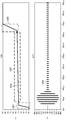
- Figure 4 illustrates key waveforms of the LLC resonant converter in a no-load startup process when the LLC resonant converter operates at a frequency approximately equal to the resonant frequency in accordance with various embodiments of the present disclosure.
- the horizontal axis of Figure 4 represents intervals of time.
- the unit of the horizontal axis is micro second.
- the first vertical axis Y1 represents the bias voltage supplied to the lossless gate driver 202.
- the second vertical axis Y2 represents the current flowing through the series resonant inductor Lr.
- the LLC resonant converter 200 operates at a switching frequency approximately equal to the resonant frequency of the resonant tank 104.
- the waveform 402 illustrates the bias voltage VB during the startup process. As shown in Figure 4, the bias voltage VB is of a slew rate approximately equal to 1000 mV/us. Alternatively, the slew rate of the bias voltage VB may be less than 1000 mV/us.
- the waveform 404 shows the current flowing through the series resonant inductor Lr (shown in Figure 2) . As shown in Figure 4, the peak current flowing through the series resonant inductor Lr is about 283 A during the startup process.
- FIG. 5 illustrates key waveforms of the LLC resonant converter in a no-load startup process when the LLC resonant converter operates at a frequency approximately equal to one and a half times the resonant frequency in accordance with various embodiments of the present disclosure.
- the LLC resonant converter 200 operates at a switching frequency approximately equal to one and a half times the resonant frequency of the resonant tank 104.
- the waveform 502 illustrates the bias voltage VB during the startup process. As shown in Figure 5, the bias voltage VB is of a slew rate approximately equal to 1000 mV/us.
- the waveform 504 shows the current flowing through the series resonant inductor Lr. As shown in Figure 5, the peak current flowing through the series resonant inductor Lr is about 226 A during the startup process.
- the peak current shown in Figure 5 is about 20% less than that shown in Figure 4. Because the results shown in Figure 4 and Figure 5 are obtained under the same operating conditions except the switching frequency, the reduced peak current shown in Figure 5 illustrates a higher switching frequency helps to reduce the peak current (a.k.a. the inrush current) during a startup process of the LLC resonant converter 200.
- the switching frequency shown in Figure 5 is merely an example.
- the switching frequency may be less than three times the resonant frequency.
- the switching frequency may be less than two times the resonant frequency.
- FIG. 6 illustrates key waveforms of the LLC resonant converter in a full-load startup process when the LLC resonant converter operates at a frequency approximately equal to the resonant frequency in accordance with various embodiments of the present disclosure.
- the waveform 602 illustrates the bias voltage VB during the startup process. As shown in Figure 6, the bias voltage VB is of a slew rate approximately equal to 1000 mV/us.
- the waveform 604 shows the current flowing through the series resonant inductor Lr. As shown in Figure 6, the peak current flowing through the series resonant inductor Lr is about 286 A during the startup process.
- FIG. 7 illustrates key waveforms of the LLC resonant converter in a full-load startup process when the LLC resonant converter operates at a frequency approximately equal to one and a half times the resonant frequency in accordance with various embodiments of the present disclosure.
- the waveform 702 illustrates the bias voltage VB during the startup process. As shown in Figure 7, the bias voltage VB is of a slew rate approximately equal to 1000 mV/us.
- the waveform 704 shows the current flowing through the series resonant inductor Lr. As shown in Figure 7, the peak current flowing through the series resonant inductor Lr is about 228 A during the startup process.
- the comparison results at different load levels show a higher switching frequency helps to reduce the peak current flowing through the LLC resonant converter 200 during a startup process.
- the switching frequency shown in Figure 5 and Figure 7 is merely an example, which should not unduly limit the scope of the claims.
- the LLC resonant converter 200 may operates at other switching frequencies such as two or three times the resonant frequency.
- the LLC resonant converter 200 may operate at a switching frequency approximately equal to the resonant frequency.
- FIGs 8-11 illustrates key waveforms of the LLC resonant converter when the bias voltage VB is of a slew rate less than that shown in Figures 4-7.
- Waveforms 802, 902, 1002 and 1102 show the slew rate of VB is about 26 mV/us.
- the waveform 804 shows the peak current is about 87 A when the LLC resonant converter 200 operates at a switching frequency approximately equal to the resonant frequency.
- the waveform 904 shows the peak current is about 57 A when the LLC resonant converter 200 operates at a switching frequency approximately equal to one and a half times the resonant frequency.
- the waveform 1004 shows the peak current is about 96 A when the LLC resonant converter 200 operates at a switching frequency approximately equal to the resonant frequency.
- the waveform 1104 shows the peak current is about 65 A when the LLC resonant converter 200 operates at a switching frequency approximately equal to one and a half times the resonant frequency.
- the higher switching frequency control mechanism shown in Figures 4-7 and the slew rate control mechanism shown in Figures 8-11 can be combined with a duty cycle control mechanism when the driver 202 shown in Figure 3 is a PWM driver. More particularly, the duty cycle of the driver 202 may be reduced so as to limit the inrush current flowing through the series resonant inductor.
- Figures 12-15 illustrates key waveforms of the LLC resonant converter when the ramp up process the bias voltage VB includes a plurality of stages.
- Waveforms 1202, 1302, 1402 and 1502 show the ramp-up process of the bias voltage VB includes a first stage 1201, a second stage 1203 and a third stage 1205.
- the bias voltage VB increases from about 0 V to about the turn-on threshold of the main power switches (e.g., switch Q1 shown in Figure 2) .
- the slew rate of the bias voltage VB in the first stage 1201 is approximately equal to 1000 mV/us.
- the bias voltage VB slowly increases from the turn-on threshold to the Miller-plateau voltage of the power switches.
- the period of the second stage 1203 is about 350 us as shown in Figure 12.
- the period shown in Figure 12 is merely an example and is not meant to limit the current embodiments.
- the bias voltage VB may stay at the second stage even longer as long as the thermal stress limitation of the LLC resonant converter 200 is not exceeded.
- the bias voltage VB increases from the Miller-plateau voltage to the steady gate drive voltage.
- the slew rate of the bias voltage VB in the third stage 1205 is approximately equal to 1000 mV/us.
- the waveform 1204 shows the peak current is about 41 A when the LLC resonant converter 200 operates at a switching frequency approximately equal to the resonant frequency.
- the waveform 1304 shows the peak current is about 12 A when the LLC resonant converter 200 operates at a switching frequency approximately equal to one and a half times the resonant frequency.
- the waveform 1404 shows the peak current is about 57 A when the LLC resonant converter 200 operates at a switching frequency approximately equal to the resonant frequency.
- the waveform 1504 shows the peak current is about 40 A when the LLC resonant converter 200 operates at a switching frequency approximately equal to one and a half times the resonant frequency.
- the comparison results at different load levels show a multi-step VB ramp-up process helps to further reduce the peak current flowing through the LLC resonant converter 200.
- the ramp-up process shown in Figures 12-15 is merely an example, which should not unduly limit the scope of the claims.
- One of ordinary skill in the art would recognize many variations, alternatives, and modifications.
- the VB ramp up process may comprise more than three stages.
- FIGs 16-19 illustrates key waveforms of the LLC resonant converter when the ramp up process the bias voltage VB includes a non-linear ramp up stage.
- Waveforms 1602, 1702, 1802 and 1902 show the ramp up process of the bias voltage VB includes a first stage 1601, a second stage 1603 and a third stage 1605.
- the first stage 1601 and the second stage 1603 are similar to the first stage 1201 and the second stage 1203 (shown in Figure 12) respectively, and hence are not discussed in further detail herein.
- the third stage 1605 is a non-linear stage. Depending on different applications and design needs, the ramp up process of the third stage 1605 may be expressed by an exponential function. In comparison with the third stage 1205 shown in Figure 12, the non-linear stage 1605 helps to reduce the thermal stress of the LLC resonant converter 200 during the startup process.
- the waveform 1604 shows the peak current is about 41 A when the LLC resonant converter 200 operates at a switching frequency approximately equal to the resonant frequency.
- the waveform 1704 shows the peak current is about 11 A when the LLC resonant converter 200 operates at a switching frequency approximately equal to one and a half times the resonant frequency.
- the waveform 1804 shows the peak current is about 57 A when the LLC resonant converter 200 operates at a switching frequency approximately equal to the resonant frequency.
- the waveform 1904 shows the peak current is about 36 A when the LLC resonant converter 200 operates at a switching frequency approximately equal to one and a half times the resonant frequency.
- the multiple ramp-up steps shown in Figures 12-19 include a slow ramp-up stage.
- the slow ramp-up stage e.g., stage 1203 in Figure 12 and stage 1603 in Figure 16
- the slope may be implemented as a plurality of small steps, which are used to emulate the slopes shown in Figure 12 and Figure 16.
- the small steps can be generated by suitable processors such as a digital signal processing (DSP) processor and/or the like.
- DSP digital signal processing
- the non-linear voltage ramp-up stage 1605 shown in Figure 16 may be implemented as a plurality of small steps.
- Figures 12 and 16 show the first stage 1201, the first stage 1601 and the third stage 1205 are a slope.
- the third stage 1605 is a non-linear curve.
- the stages 1201, 1205, 1601 and 1605 may further comprise a plurality of sub-segments. Each sub-segment may be a linear curve, a non-linear curve, any combinations thereof and/or the like.
- the average voltage of the slow ramp-up stage (e.g., stage 1203 in Figure 12 and stage 1603 in Figure 16) is in a range from the turn-on threshold voltage of the switches and the Miller-plateau voltage of the switches (e.g., switch Q1 of Figure 2) .
- a controller (not shown) may be employed to determine the average voltage based upon detecting and analyzing a variety of operating variables of the LLC resonant converter 200.
- the variables include the input voltage, the input current, the output voltage, the output current, the switching frequency, any combinations thereof and/or the like.
Landscapes
- Engineering & Computer Science (AREA)
- Power Engineering (AREA)
- Dc-Dc Converters (AREA)
Abstract
Un procédé selon l'invention comprend les étapes consistant à utiliser un convertisseur à résonance comprenant un réseau de commutation comprenant une pluralité d'interrupteurs, une cuve de résonance couplée entre le réseau de commutation et un transformateur, ladite cuve de résonance comprenant une bobine d'induction de résonance série couplée à un réseau de commutation et au transformateur et un condensateur de résonance série couplé au réseau de commutation et au transformateur, ainsi qu'un circuit de commande à tension de polarisation ajustable et configurant le réseau de commutation de manière à fonctionner à une fréquence de commutation supérieure à une fréquence de résonance de la cuve de résonance en réaction à un procédé d'amorçage du convertisseur à résonance.
Applications Claiming Priority (2)
| Application Number | Priority Date | Filing Date | Title |
|---|---|---|---|
| US14/074,194 | 2013-11-07 | ||
| US14/074,194 US9350260B2 (en) | 2013-11-07 | 2013-11-07 | Startup method and system for resonant converters |
Publications (2)
| Publication Number | Publication Date |
|---|---|
| WO2015067202A2 true WO2015067202A2 (fr) | 2015-05-14 |
| WO2015067202A3 WO2015067202A3 (fr) | 2015-09-24 |
Family
ID=53006908
Family Applications (1)
| Application Number | Title | Priority Date | Filing Date |
|---|---|---|---|
| PCT/CN2014/090534 Ceased WO2015067202A2 (fr) | 2013-11-07 | 2014-11-07 | Procédé et système d'amorçage pour convertisseurs à résonance |
Country Status (2)
| Country | Link |
|---|---|
| US (1) | US9350260B2 (fr) |
| WO (1) | WO2015067202A2 (fr) |
Cited By (1)
| Publication number | Priority date | Publication date | Assignee | Title |
|---|---|---|---|---|
| CN105932881A (zh) * | 2016-07-08 | 2016-09-07 | 西安电子科技大学 | 全桥llc谐振变换器及其同步整流驱动方法 |
Families Citing this family (16)
| Publication number | Priority date | Publication date | Assignee | Title |
|---|---|---|---|---|
| US9184655B2 (en) * | 2014-03-17 | 2015-11-10 | Semiconductor Components Industries, Llc | Method and semiconductor device for a dedicated startup sequence in a resonant converter |
| US9819274B2 (en) | 2014-11-20 | 2017-11-14 | Microchip Technology Incorporated | Start-up controller for a power converter |
| US9590492B2 (en) * | 2014-12-18 | 2017-03-07 | Infineon Technologies Austria Ag | System and method for a switched-mode power supply |
| US9912243B2 (en) | 2015-06-01 | 2018-03-06 | Microchip Technology Incorporated | Reducing power in a power converter when in a standby mode |
| US10277130B2 (en) | 2015-06-01 | 2019-04-30 | Microchip Technolgoy Incorporated | Primary-side start-up method and circuit arrangement for a series-parallel resonant power converter |
| US9705408B2 (en) | 2015-08-21 | 2017-07-11 | Microchip Technology Incorporated | Power converter with sleep/wake mode |
| US10333410B2 (en) * | 2016-09-15 | 2019-06-25 | Futurewei Technologies, Inc. | Common-mode (CM) electromagnetic interference (EMI) reduction in resonant converters |
| EP3534519B1 (fr) * | 2016-10-26 | 2022-06-01 | Mitsubishi Electric Corporation | Dispositif de conversion de puissance |
| US10673323B2 (en) | 2016-10-27 | 2020-06-02 | University Of Florida Research Foundation, Incorporated | Loop noise balance technique for CM EMI noise reduction of the full bridge LLC resonant converter |
| US10193457B1 (en) | 2017-09-15 | 2019-01-29 | Abb Schweiz Ag | System and method for starting up a high density isolated DC-to-DC power converter |
| US10320283B1 (en) | 2018-01-26 | 2019-06-11 | Universal Lighting Technologies, Inc. | Resonant converter with pre-charging circuit for startup protection |
| US10205381B1 (en) * | 2018-05-10 | 2019-02-12 | Vlt, Inc. | Start-up control in power systems using fixed-ratio power conversion |
| US10707746B1 (en) | 2018-05-31 | 2020-07-07 | Universal Lighting Technologies, Inc. | Power converter with independent multiplier input for PFC circuit |
| TWI705652B (zh) * | 2019-03-15 | 2020-09-21 | 國立臺灣大學 | 具磁通平衡控制電路之llc諧振轉換器 |
| WO2020190673A1 (fr) * | 2019-03-15 | 2020-09-24 | Murata Manufacturing Co., Ltd. | Démarrage progressif pour convertisseurs résonants |
| EP4586486A1 (fr) * | 2024-01-12 | 2025-07-16 | Schneider Toshiba Inverter Europe SAS | Augmentation de tension de liaison cc |
Family Cites Families (18)
| Publication number | Priority date | Publication date | Assignee | Title |
|---|---|---|---|---|
| CN101142730A (zh) | 2004-11-05 | 2008-03-12 | 国际整流器公司 | 具有减小的di/dt和延迟补偿的驱动电路及方法 |
| TWI326963B (en) * | 2006-12-14 | 2010-07-01 | Tungnan Inst Of Technology | Resonant converter and synchronous rectification driving circuit thereof |
| US7808299B2 (en) | 2007-12-14 | 2010-10-05 | Astec International Limited | Switching power converter with reduced switching losses |
| US7742318B2 (en) * | 2008-06-10 | 2010-06-22 | Virginia Tech Intellectual Properties, Inc. | Multi-element resonant converters |
| US7660133B1 (en) * | 2008-11-04 | 2010-02-09 | Champion Microelectronic Corporation | Resonant switching converter having operating modes above and below resonant frequency |
| US8717783B2 (en) * | 2009-10-30 | 2014-05-06 | Delta Electronics (Shanghai) Co., Ltd. | Method and apparatus for regulating gain within a resonant converter |
| JP5633778B2 (ja) | 2010-04-01 | 2014-12-03 | ミネベア株式会社 | スイッチング電源装置 |
| US8456868B2 (en) * | 2010-04-30 | 2013-06-04 | Infineon Technologies Ag | Controller for a resonant switched-mode power converter |
| CN102263508B (zh) * | 2010-05-28 | 2014-12-17 | 台达电子工业股份有限公司 | 谐振型转换系统以及过电流保护方法 |
| CN103518317B (zh) * | 2011-05-12 | 2016-08-17 | 株式会社村田制作所 | 开关电源装置 |
| US9948204B2 (en) | 2011-05-19 | 2018-04-17 | Enphase Energy, Inc. | Method and apparatus for controlling resonant converter output power |
| JP5690654B2 (ja) | 2011-05-25 | 2015-03-25 | 株式会社日立製作所 | 直流電源装置 |
| CN202282743U (zh) * | 2011-09-29 | 2012-06-20 | 南京博兰得电子科技有限公司 | 一种谐振变换器控制装置 |
| KR101920673B1 (ko) | 2012-01-31 | 2018-11-22 | 주식회사 솔루엠 | 컨버터 구동회로, 듀얼 모드 llc 공진 컨버터 시스템 및 듀얼 모드 llc 공진 컨버터 구동방법 |
| CN102709896B (zh) | 2012-05-03 | 2015-01-21 | 华为技术有限公司 | 箝位保护电路、谐振电路及变换器 |
| CN103715906B (zh) * | 2012-09-29 | 2017-05-24 | 台达电子工业股份有限公司 | 谐振转换器混合控制方法、谐振转换器系统及混合控制器 |
| US9077255B2 (en) * | 2013-01-11 | 2015-07-07 | Futurewei Technologies, Inc. | Resonant converters and methods |
| CN103280774B (zh) | 2013-05-17 | 2015-09-09 | 华为技术有限公司 | 功率转换电路及其驱动装置、开关管保护装置和方法 |
-
2013
- 2013-11-07 US US14/074,194 patent/US9350260B2/en active Active
-
2014
- 2014-11-07 WO PCT/CN2014/090534 patent/WO2015067202A2/fr not_active Ceased
Cited By (1)
| Publication number | Priority date | Publication date | Assignee | Title |
|---|---|---|---|---|
| CN105932881A (zh) * | 2016-07-08 | 2016-09-07 | 西安电子科技大学 | 全桥llc谐振变换器及其同步整流驱动方法 |
Also Published As
| Publication number | Publication date |
|---|---|
| WO2015067202A3 (fr) | 2015-09-24 |
| US9350260B2 (en) | 2016-05-24 |
| US20150124488A1 (en) | 2015-05-07 |
Similar Documents
| Publication | Publication Date | Title |
|---|---|---|
| US9350260B2 (en) | Startup method and system for resonant converters | |
| US11909326B2 (en) | Parallel hybrid converter apparatus and method | |
| US9548668B2 (en) | Hybrid power converter and method | |
| US9876435B2 (en) | Gate drive apparatus for resonant converters | |
| US9812977B2 (en) | Resonant converters with an improved voltage regulation range | |
| US9484821B2 (en) | Adjustable resonant apparatus for power converters | |
| US9178438B2 (en) | Apparatus for resonant converters | |
| US9190911B2 (en) | Auxiliary resonant apparatus for LLC converters | |
| US9787200B2 (en) | Resonant converters with synchronous rectifier feedback | |
| US9998018B2 (en) | Resonant converters and methods | |
| US9774271B2 (en) | Apparatus and method for multiple primary bridge resonant converters | |
| US9461554B2 (en) | Hybrid converter using a resonant stage and a non-isolated stage | |
| US9595877B2 (en) | Secondary side hybrid converter apparatus and method | |
| JP2016533704A (ja) | 高効率共振変換器のための装置および方法 | |
| US8970067B2 (en) | Hybrid DC/DC converters and methods |
Legal Events
| Date | Code | Title | Description |
|---|---|---|---|
| NENP | Non-entry into the national phase |
Ref country code: DE |
|
| 122 | Ep: pct application non-entry in european phase |
Ref document number: 14861079 Country of ref document: EP Kind code of ref document: A2 |